Embed Size (px)
Citation preview
1DLPA036B–July 2013–Revised February 2018Submit Documentation Feedback
Copyright © 2013–2018, Texas Instruments Incorporated
Using DLP® LightCrafter™ 4500 Triggers to Synchronize Cameras toPatterns
Application ReportDLPA036B–July 2013–Revised February 2018
Using DLP® LightCrafter™ 4500 Triggers to SynchronizeCameras to Patterns
ABSTRACTThis document describes how to use the DLP® LightCrafter™ 4500 with the global trigger function ofindustrial USB 2, USB 3, FireWire, and GigE CCD cameras from Point Grey Research, The ImagingSource, and other manufacturers.
Contents1 Introduction ................................................................................................................... 22 Connections .................................................................................................................. 3
2.1 Connector J14....................................................................................................... 32.2 Connectors J13 and J15 ........................................................................................... 42.3 Connectors J10 and J12 ........................................................................................... 5
3 DLP LightCrafter 4500 and The Imaging Source Firewire Camera ................................................... 64 Conclusion .................................................................................................................... 95 Resources .................................................................................................................... 9
List of Figures
1 DLP LightCrafter 4500 Controller Board.................................................................................. 22 Schematic of J14 – Trigger Out 1 and 2.................................................................................. 33 Schematic of J13 ............................................................................................................ 44 Jumper Locations for Setting Voltage Levels on J13 (Trigger Out 1) and J15 (Trigger Out 2) ................... 45 Jumper Locations for Setting Voltage Levels on J10 (Trigger In 1) and J12 (Trigger In 2)........................ 56 Example Setup of DLP LightCrafter 4500 and Firewire Camera from The Imaging Source ...................... 67 DLP LightCrafter 4500 Control Software – Pattern Sequence/Sequence Settings Tab............................ 78 DLP LightCrafter 4500 Control Software – Pattern Sequence/Trigger Controls Tab ............................... 8
Introduction www.ti.com
2 DLPA036B–July 2013–Revised February 2018Submit Documentation Feedback
Copyright © 2013–2018, Texas Instruments Incorporated
Using DLP® LightCrafter™ 4500 Triggers to Synchronize Cameras toPatterns
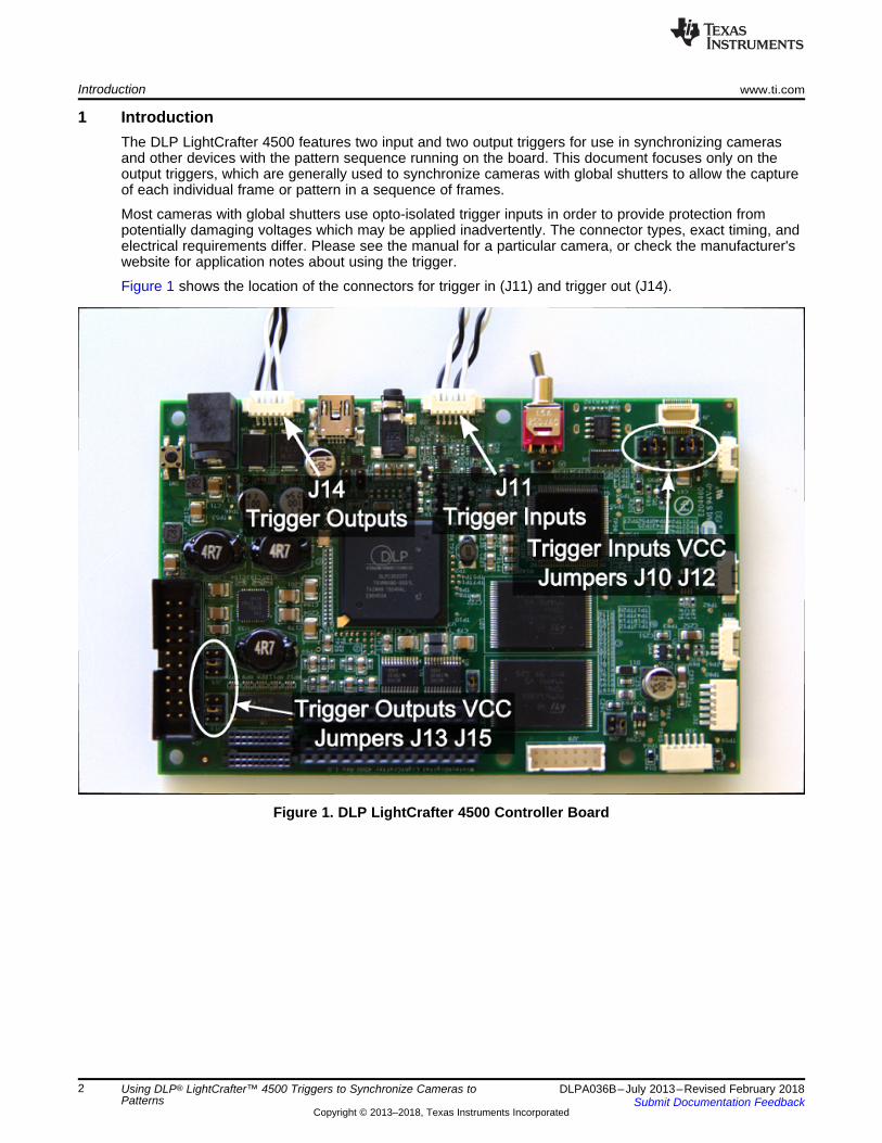
1 IntroductionThe DLP LightCrafter 4500 features two input and two output triggers for use in synchronizing camerasand other devices with the pattern sequence running on the board. This document focuses only on theoutput triggers, which are generally used to synchronize cameras with global shutters to allow the captureof each individual frame or pattern in a sequence of frames.
Most cameras with global shutters use opto-isolated trigger inputs in order to provide protection frompotentially damaging voltages which may be applied inadvertently. The connector types, exact timing, andelectrical requirements differ. Please see the manual for a particular camera, or check the manufacturer'swebsite for application notes about using the trigger.
Figure 1 shows the location of the connectors for trigger in (J11) and trigger out (J14).
Figure 1. DLP LightCrafter 4500 Controller Board
www.ti.com Connections
3DLPA036B–July 2013–Revised February 2018Submit Documentation Feedback
Copyright © 2013–2018, Texas Instruments Incorporated
Using DLP® LightCrafter™ 4500 Triggers to Synchronize Cameras toPatterns
2 Connections
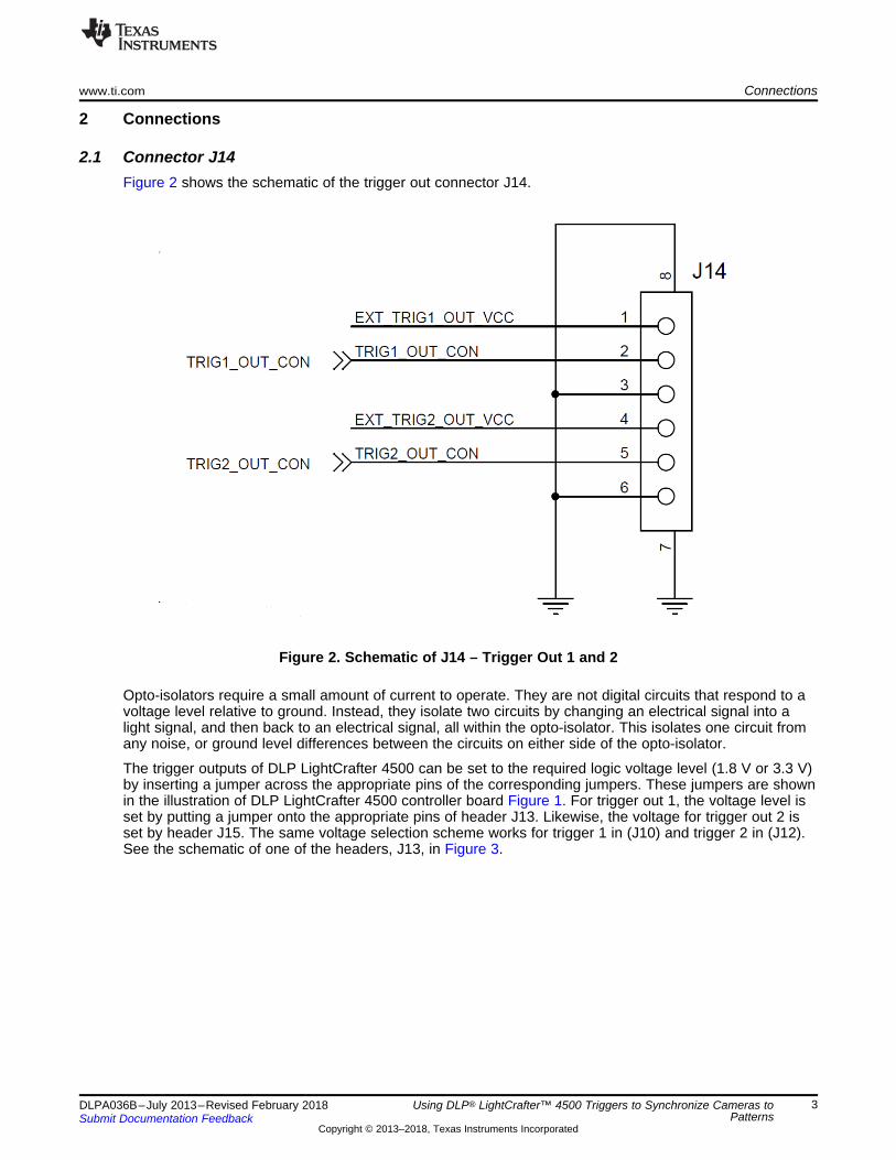
2.1 Connector J14Figure 2 shows the schematic of the trigger out connector J14.
Figure 2. Schematic of J14 – Trigger Out 1 and 2
Opto-isolators require a small amount of current to operate. They are not digital circuits that respond to avoltage level relative to ground. Instead, they isolate two circuits by changing an electrical signal into alight signal, and then back to an electrical signal, all within the opto-isolator. This isolates one circuit fromany noise, or ground level differences between the circuits on either side of the opto-isolator.
The trigger outputs of DLP LightCrafter 4500 can be set to the required logic voltage level (1.8 V or 3.3 V)by inserting a jumper across the appropriate pins of the corresponding jumpers. These jumpers are shownin the illustration of DLP LightCrafter 4500 controller board Figure 1. For trigger out 1, the voltage level isset by putting a jumper onto the appropriate pins of header J13. Likewise, the voltage for trigger out 2 isset by header J15. The same voltage selection scheme works for trigger 1 in (J10) and trigger 2 in (J12).See the schematic of one of the headers, J13, in Figure 3.
3.3 V
1.8 V
3.3 V
1.8 V
6
2 4 6
J13
951206-8622-AR
P1P8V_TOUT
P3P3V
EXT TRIG1_OUT_VCC
2 4 6
1 3 5
1 3 5
Connections www.ti.com
4 DLPA036B–July 2013–Revised February 2018Submit Documentation Feedback
Copyright © 2013–2018, Texas Instruments Incorporated
Using DLP® LightCrafter™ 4500 Triggers to Synchronize Cameras toPatterns
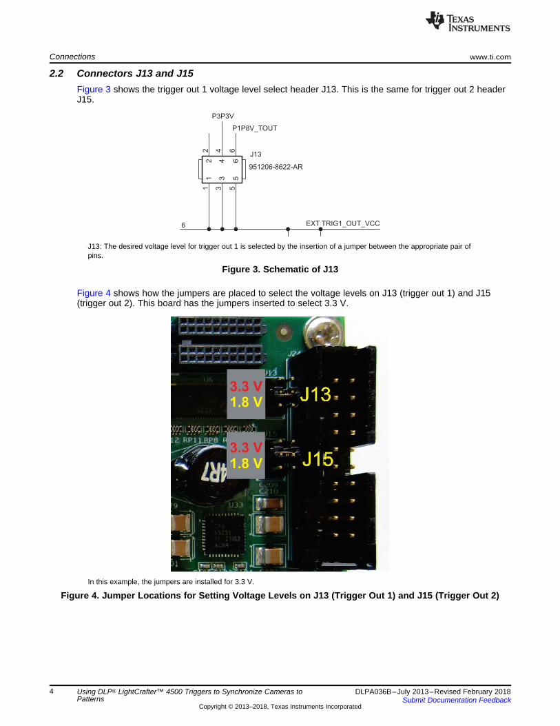
2.2 Connectors J13 and J15Figure 3 shows the trigger out 1 voltage level select header J13. This is the same for trigger out 2 headerJ15.
J13: The desired voltage level for trigger out 1 is selected by the insertion of a jumper between the appropriate pair ofpins.
Figure 3. Schematic of J13
Figure 4 shows how the jumpers are placed to select the voltage levels on J13 (trigger out 1) and J15(trigger out 2). This board has the jumpers inserted to select 3.3 V.
In this example, the jumpers are installed for 3.3 V.
Figure 4. Jumper Locations for Setting Voltage Levels on J13 (Trigger Out 1) and J15 (Trigger Out 2)
3.3 V
1.8 V
3.3 V
1.8 V
www.ti.com Connections
5DLPA036B–July 2013–Revised February 2018Submit Documentation Feedback
Copyright © 2013–2018, Texas Instruments Incorporated
Using DLP® LightCrafter™ 4500 Triggers to Synchronize Cameras toPatterns
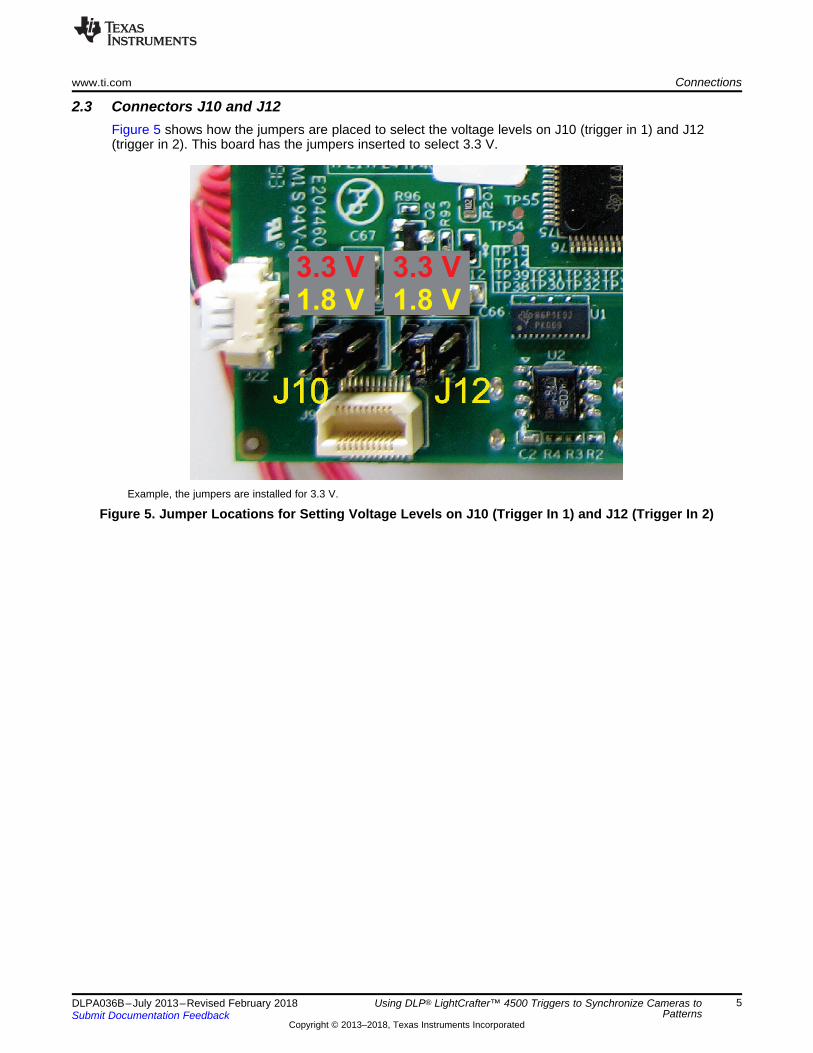
2.3 Connectors J10 and J12Figure 5 shows how the jumpers are placed to select the voltage levels on J10 (trigger in 1) and J12(trigger in 2). This board has the jumpers inserted to select 3.3 V.
Example, the jumpers are installed for 3.3 V.
Figure 5. Jumper Locations for Setting Voltage Levels on J10 (Trigger In 1) and J12 (Trigger In 2)
DLP LightCrafter 4500 and The Imaging Source Firewire Camera www.ti.com
6 DLPA036B–July 2013–Revised February 2018Submit Documentation Feedback
Copyright © 2013–2018, Texas Instruments Incorporated
Using DLP® LightCrafter™ 4500 Triggers to Synchronize Cameras toPatterns
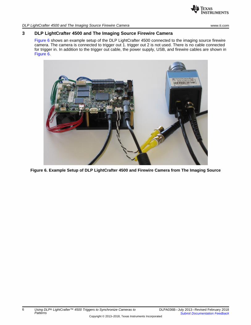
3 DLP LightCrafter 4500 and The Imaging Source Firewire CameraFigure 6 shows an example setup of the DLP LightCrafter 4500 connected to the imaging source firewirecamera. The camera is connected to trigger out 1. trigger out 2 is not used. There is no cable connectedfor trigger in. In addition to the trigger out cable, the power supply, USB, and firewire cables are shown inFigure 6.
Figure 6. Example Setup of DLP LightCrafter 4500 and Firewire Camera from The Imaging Source
www.ti.com DLP LightCrafter 4500 and The Imaging Source Firewire Camera
7DLPA036B–July 2013–Revised February 2018Submit Documentation Feedback
Copyright © 2013–2018, Texas Instruments Incorporated
Using DLP® LightCrafter™ 4500 Triggers to Synchronize Cameras toPatterns
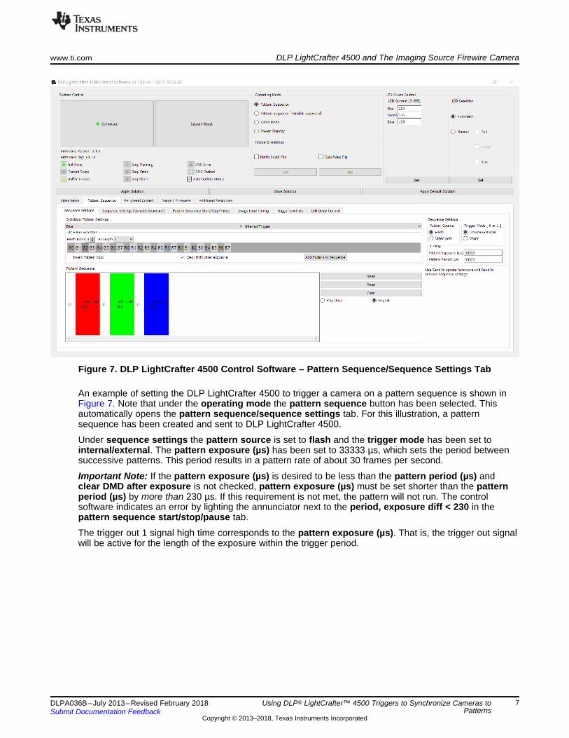
Figure 7. DLP LightCrafter 4500 Control Software – Pattern Sequence/Sequence Settings Tab
An example of setting the DLP LightCrafter 4500 to trigger a camera on a pattern sequence is shown inFigure 7. Note that under the operating mode the pattern sequence button has been selected. Thisautomatically opens the pattern sequence/sequence settings tab. For this illustration, a patternsequence has been created and sent to DLP LightCrafter 4500.
Under sequence settings the pattern source is set to flash and the trigger mode has been set tointernal/external. The pattern exposure (µs) has been set to 33333 µs, which sets the period betweensuccessive patterns. This period results in a pattern rate of about 30 frames per second.
Important Note: If the pattern exposure (µs) is desired to be less than the pattern period (µs) andclear DMD after exposure is not checked, pattern exposure (µs) must be set shorter than the patternperiod (µs) by more than 230 µs. If this requirement is not met, the pattern will not run. The controlsoftware indicates an error by lighting the annunciator next to the period, exposure diff < 230 in thepattern sequence start/stop/pause tab.
The trigger out 1 signal high time corresponds to the pattern exposure (µs). That is, the trigger out signalwill be active for the length of the exposure within the trigger period.
DLP LightCrafter 4500 and The Imaging Source Firewire Camera www.ti.com
8 DLPA036B–July 2013–Revised February 2018Submit Documentation Feedback
Copyright © 2013–2018, Texas Instruments Incorporated
Using DLP® LightCrafter™ 4500 Triggers to Synchronize Cameras toPatterns
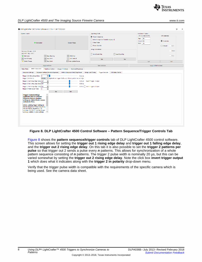
Figure 8. DLP LightCrafter 4500 Control Software – Pattern Sequence/Trigger Controls Tab
Figure 8 shows the pattern sequence/trigger controls tab of DLP LightCrafter 4500 control software.This screen allows for setting the trigger out 1 rising edge delay and trigger out 1 falling edge delay,and the trigger out 2 rising edge delay. On this tab it is also possible to set the trigger 2 patterns perpulse so that trigger out 2 sends a pulse every n patterns. This allows for synchronization of a wholepattern sequence consisting of n patterns. The trigger 2 pulse width is nominally 20 µs, but this can bevaried somewhat by setting the trigger out 2 rising edge delay. Note the click box invert trigger output1 which does what it indicates along with the trigger 2 in polarity drop-down menu.
Verify that the trigger pulse width is compatible with the requirements of the specific camera which isbeing used. See the camera data sheet.
www.ti.com Conclusion
9DLPA036B–July 2013–Revised February 2018Submit Documentation Feedback
Copyright © 2013–2018, Texas Instruments Incorporated
Revision History
4 ConclusionThe trigger features of the DLP LightCrafter 4500 offer flexible means of synchronizing cameras or otherdevices to the pattern sequences projected by the module. Many different voltage level, polarity, andtiming requirements can be accommodated by appropriate configuration of the DLP LightCrafter 4500through its control software. Other resources are available for understanding and utilizing these and otherfeatures of the DLP LightCrafter 4500. Visit www.ti.com/dlp to download data sheets and other supportingdocuments.
5 ResourcesThe following is a list of suggested hardware:• Trigger connector housing (connects to J11, J14)
– Molex part number: 51021-0600– Digi-Key part number: WM1724-ND
• Crimp pins (6 each required for the trigger housing)– Molex part number: 50079-8100– Digi-Key part number: WM2023-ND
Revision History
Changes from A Revision (June 2014) to B Revision .................................................................................................... Page
• Updated GUI screenshot in Figure 7 and corresponding description .............................................................. 7• Changed information related to pattern exposure, pattern period difference requirements, and trigger out 1 in Section 3. 7• Updated GUI screenshot in Figure 8 and corresponding description .............................................................. 8
Changes from Original (July 2013) to A Revision ........................................................................................................... Page
• Added section titles and updated image titles ......................................................................................... 2• Removed 5.0-V trigger option ........................................................................................................... 3

IMPORTANT NOTICE FOR TI DESIGN INFORMATION AND RESOURCES
Texas Instruments Incorporated (‘TI”) technical, application or other design advice, services or information, including, but not limited to,reference designs and materials relating to evaluation modules, (collectively, “TI Resources”) are intended to assist designers who aredeveloping applications that incorporate TI products; by downloading, accessing or using any particular TI Resource in any way, you(individually or, if you are acting on behalf of a company, your company) agree to use it solely for this purpose and subject to the terms ofthis Notice.TI’s provision of TI Resources does not expand or otherwise alter TI’s applicable published warranties or warranty disclaimers for TIproducts, and no additional obligations or liabilities arise from TI providing such TI Resources. TI reserves the right to make corrections,enhancements, improvements and other changes to its TI Resources.You understand and agree that you remain responsible for using your independent analysis, evaluation and judgment in designing yourapplications and that you have full and exclusive responsibility to assure the safety of your applications and compliance of your applications(and of all TI products used in or for your applications) with all applicable regulations, laws and other applicable requirements. Yourepresent that, with respect to your applications, you have all the necessary expertise to create and implement safeguards that (1)anticipate dangerous consequences of failures, (2) monitor failures and their consequences, and (3) lessen the likelihood of failures thatmight cause harm and take appropriate actions. You agree that prior to using or distributing any applications that include TI products, youwill thoroughly test such applications and the functionality of such TI products as used in such applications. TI has not conducted anytesting other than that specifically described in the published documentation for a particular TI Resource.You are authorized to use, copy and modify any individual TI Resource only in connection with the development of applications that includethe TI product(s) identified in such TI Resource. NO OTHER LICENSE, EXPRESS OR IMPLIED, BY ESTOPPEL OR OTHERWISE TOANY OTHER TI INTELLECTUAL PROPERTY RIGHT, AND NO LICENSE TO ANY TECHNOLOGY OR INTELLECTUAL PROPERTYRIGHT OF TI OR ANY THIRD PARTY IS GRANTED HEREIN, including but not limited to any patent right, copyright, mask work right, orother intellectual property right relating to any combination, machine, or process in which TI products or services are used. Informationregarding or referencing third-party products or services does not constitute a license to use such products or services, or a warranty orendorsement thereof. Use of TI Resources may require a license from a third party under the patents or other intellectual property of thethird party, or a license from TI under the patents or other intellectual property of TI.TI RESOURCES ARE PROVIDED “AS IS” AND WITH ALL FAULTS. TI DISCLAIMS ALL OTHER WARRANTIES ORREPRESENTATIONS, EXPRESS OR IMPLIED, REGARDING TI RESOURCES OR USE THEREOF, INCLUDING BUT NOT LIMITED TOACCURACY OR COMPLETENESS, TITLE, ANY EPIDEMIC FAILURE WARRANTY AND ANY IMPLIED WARRANTIES OFMERCHANTABILITY, FITNESS FOR A PARTICULAR PURPOSE, AND NON-INFRINGEMENT OF ANY THIRD PARTY INTELLECTUALPROPERTY RIGHTS.TI SHALL NOT BE LIABLE FOR AND SHALL NOT DEFEND OR INDEMNIFY YOU AGAINST ANY CLAIM, INCLUDING BUT NOTLIMITED TO ANY INFRINGEMENT CLAIM THAT RELATES TO OR IS BASED ON ANY COMBINATION OF PRODUCTS EVEN IFDESCRIBED IN TI RESOURCES OR OTHERWISE. IN NO EVENT SHALL TI BE LIABLE FOR ANY ACTUAL, DIRECT, SPECIAL,COLLATERAL, INDIRECT, PUNITIVE, INCIDENTAL, CONSEQUENTIAL OR EXEMPLARY DAMAGES IN CONNECTION WITH ORARISING OUT OF TI RESOURCES OR USE THEREOF, AND REGARDLESS OF WHETHER TI HAS BEEN ADVISED OF THEPOSSIBILITY OF SUCH DAMAGES.You agree to fully indemnify TI and its representatives against any damages, costs, losses, and/or liabilities arising out of your non-compliance with the terms and provisions of this Notice.This Notice applies to TI Resources. Additional terms apply to the use and purchase of certain types of materials, TI products and services.These include; without limitation, TI’s standard terms for semiconductor products http://www.ti.com/sc/docs/stdterms.htm), evaluationmodules, and samples (http://www.ti.com/sc/docs/sampterms.htm).
Mailing Address: Texas Instruments, Post Office Box 655303, Dallas, Texas 75265Copyright © 2018, Texas Instruments Incorporated


![[XLS]comptroller.defense.govcomptroller.defense.gov/Portals/45/Documents/defbudget/... · Web view22069572 25884975 25806130 25804188 4500 4500 4500 4500 23000 23000 23000 23000 4500](https://img.pdfslide.net/doc/110x75/5ab602207f8b9a7c5b8d4b5a/xls-view22069572-25884975-25806130-25804188-4500-4500-4500-4500-23000-23000-23000.jpg)