Embed Size (px)
Citation preview
28 mentor.com/mechanical
By Hidebumi Takahashi, Mitsubishi Materials Corporation, Advanced Materials & Tools Company, Machining Technology Center
he Mitsubishi Group is a huge Japanese industrial conglomerate and Mitsubishi Materials Corporation is one of
the subsidiary companies of Mitsubishi Mining Company Ltd. and has been in existence for approximately 100 years. Its Advanced Materials & Tools Company and its consolidated subsidiary companies employ approximately 6,800 people worldwide, making and delivering a wide range of machine
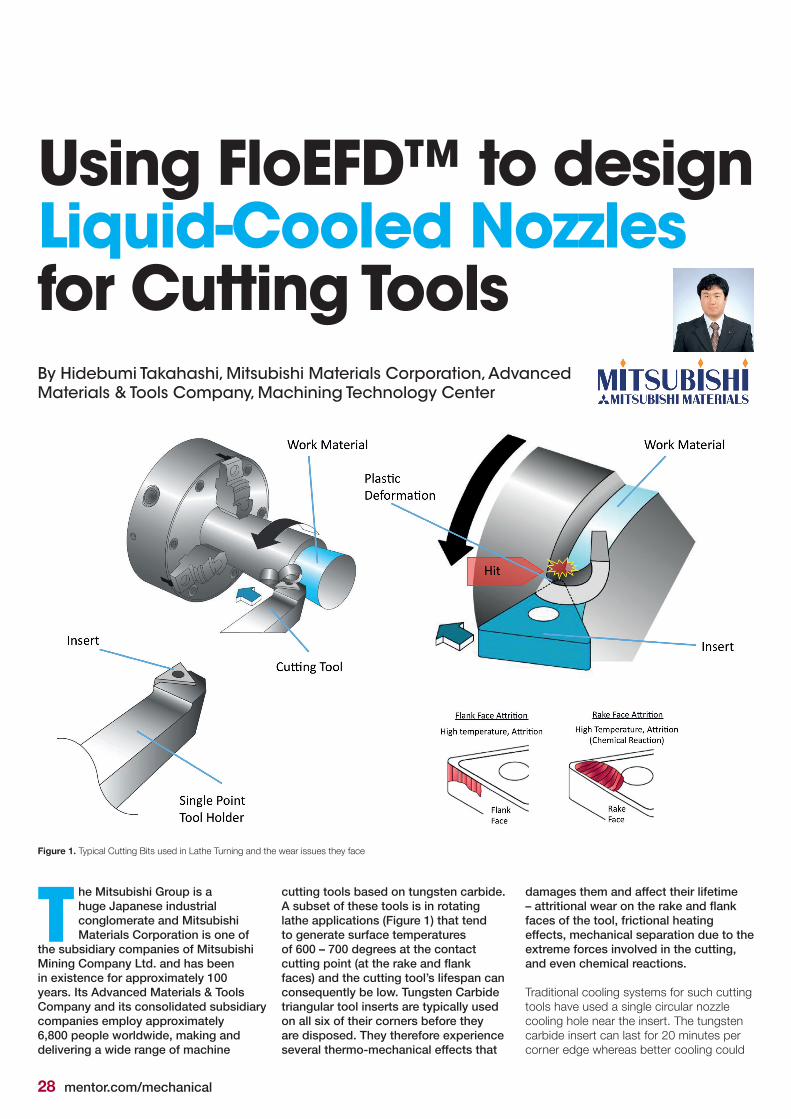
TFigure 1. Typical Cutting Bits used in Lathe Turning and the wear issues they face
Using FloEFD™ to design Liquid-Cooled Nozzles for Cutting Tools
cutting tools based on tungsten carbide. A subset of these tools is in rotating lathe applications (Figure 1) that tend to generate surface temperatures of 600 – 700 degrees at the contact cutting point (at the rake and flank faces) and the cutting tool’s lifespan can consequently be low. Tungsten Carbide triangular tool inserts are typically used on all six of their corners before they are disposed. They therefore experience several thermo-mechanical effects that
damages them and affect their lifetime – attritional wear on the rake and flank faces of the tool, frictional heating effects, mechanical separation due to the extreme forces involved in the cutting, and even chemical reactions.
Traditional cooling systems for such cutting tools have used a single circular nozzle cooling hole near the insert. The tungsten carbide insert can last for 20 minutes per corner edge whereas better cooling could
mentor.com/mechanical 29
increasetheinsert’slifetimeby40%,to28-30 minutes per corner edge. Such well-cooled tool holder’s lifetime performance is an advantage to productivity for cutting tool users.
Mitsubishi turned to Prof Obikawa of the Institute of Industrial Science at Tokyo University and established an academic-industrial partnership to extend the life of their tools. He came up with ideas for new cooling technology for the Mitsubishi tool holder that needed to be tested. The goal of the new cooling technology was to reduce extreme frictional heat generated while cutting (Figure 2), which in turn has the adverse effect of reducing product lifetimes. Prof Obikawa’s “Jet Coolant Tech” (JC Technology) came out of the collaboration.
Manufacturing
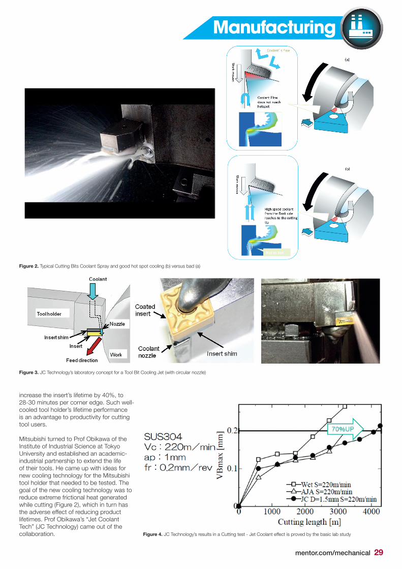
Figure 2. Typical Cutting Bits Coolant Spray and good hot spot cooling (b) versus bad (a)
Figure 3. JC Technology’s laboratory concept for a Tool Bit Cooling Jet (with circular nozzle)
Figure 4. JC Technology’s results in a Cutting test - Jet Coolant effect is proved by the basic lab study
30 mentor.com/mechanical
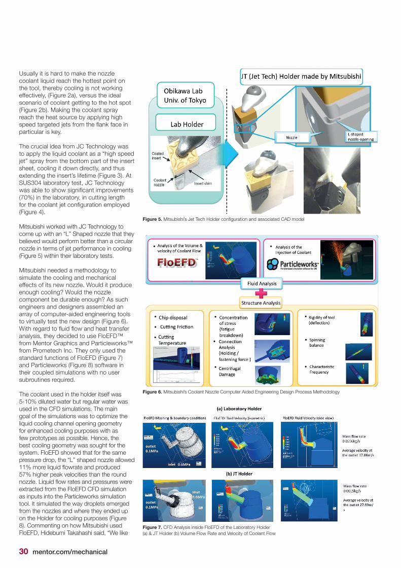
Usually it is hard to make the nozzle coolant liquid reach the hottest point on the tool, thereby cooling is not working effectively, (Figure 2a), versus the ideal scenario of coolant getting to the hot spot (Figure 2b). Making the coolant spray reach the heat source by applying high speedtargetedjetsfromtheflankfaceinparticular is key. The crucial idea from JC Technology was to apply the liquid coolant as a “high speed jet” spray from the bottom part of the insert sheet, cooling it down directly, and thus extending the insert’s lifetime (Figure 3). At SUS304 laboratory test, JC Technology wasabletoshowsignificantimprovements(70%)inthelaboratory,incuttinglengthforthecoolantjetconfigurationemployed(Figure 4). Mitsubishi worked with JC Technology to come up with an “L” Shaped nozzle that they believed would perform better than a circular nozzle in terms of jet performance in cooling (Figure 5) within their laboratory tests. Mitsubishi needed a methodology to simulate the cooling and mechanical effects of its new nozzle. Would it produce enoughcooling?Wouldthenozzlecomponentbedurableenough?Assuchengineers and designers assembled an array of computer-aided engineering tools to virtually test the new design (Figure 6). Withregardtofluidflowandheattransferanalysis, they decided to use FloEFD™ from Mentor Graphics and Particleworks™ from Prometech Inc. They only used the standard functions of FloEFD (Figure 7) and Particleworks (Figure 8) software in their coupled simulations with no user subroutines required.
The coolant used in the holder itself was 5-10%dilutedwaterbutregularwaterwasused in the CFD simulations. The main goal of the simulations was to optimize the liquid cooling channel opening geometry for enhanced cooling purposes with as few prototypes as possible. Hence, the best cooling geometry was sought for the system. FloEFD showed that for the same pressure drop, the “L” shaped nozzle allowed 11%moreliquidflowrateandproduced57%higherpeakvelocitiesthantheroundnozzle.Liquidflowratesandpressureswereextracted from the FloEFD CFD simulation as inputs into the Particleworks simulation tool. It simulated the way droplets emerged from the nozzles and where they ended up on the Holder for cooling purposes (Figure 8). Commenting on how Mitsubishi used FloEFD, Hidebumi Takahashi said, “We like
Figure 5.Mitsubishi’sJetTechHolderconfigurationandassociatedCADmodel
Figure 6. Mitsubishi’s Coolant Nozzle Computer Aided Engineering Design Process Methodology
Figure 7. CFD Analysis inside FloEFD of the Laboratory Holder (a) & JT Holder (b) Volume Flow Rate and Velocity of Coolant Flow
mentor.com/mechanical 31
FloEFD because it is fast in calculation for steady analysis. Since we have no specialist CFD experts, our designers take care of simulation analysis. FloEFD is the best for CFDbecauseofitssimplifiedauto-meshingsetting inside our preferred CAD package, PTC Creo. We found the cut cell CFD function to be very valuable.”
Subsequent experimental test measurements of the JT Holder system prototype created by this approach proved to be very satisfactory in thermal performance as was structural simulation analysis of the rigidity and durability of the nozzle. The methodology devised by Mitsubishi allowed them to patent the JT Tech nozzle (Figure 9) they devised and can be used to create other Holder nozzleconfigurationsrelativelyquickly.In future Mitsubishi would like to see a closercouplingofthetwofluidsimulationsoftware tools for similar analyses.
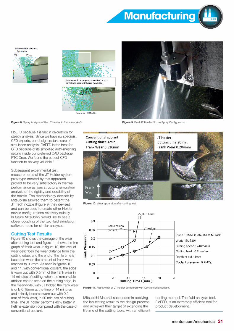
Cutting Test ResultsFigure 10 shows the damage of the wear aftercuttingtestandfigure11showsthelinegraphoffrankwear.Infigure10,thelevelofwear describes the wear distance from the cutting edge, and the end of the life time is based on when the amount of frank wear reachesto0.2mm.Asseeninfigures10and 11, with conventional coolant, the edge is worn out with 0.5mm of the frank wear in 14 minutes of cutting, when the remarkable attrition can be seen on the cutting edge, in the meanwhile, with JT holder, the frank wear is only 0.15mm at the time of 14 minutes anditfinallybecamewornoutwith0.2mm of frank wear, in 20 minutes of cutting time.TheJTholderperforms40%betterinlifetime extension compared with the case of conventional coolant.
Figure 10. Wear apparatus after cutting test.
Figure 11. Frank wear of JT holder compared with Conventional coolant.
Figure 8. Spray Analysis of the JT Holder in Particleworks™ Figure 9.FinalJTHolderNozzleSprayConfiguration
Mitsubishi Material succeeded in applying the lab testing result to the design process and achieved their target of extending the lifetimeofthecuttingtools,withanefficient
coolingmethod.Thefluidanalysistool,FloEFD,isanextremelyefficienttoolforproduct development.
Manufacturing