Embed Size (px)
Citation preview

The 14th IFToMM World Congress, Taipei, Taiwan, October 25-30, 2015
DOI Number: 10.6567/IFToMM.14TH.WC.OS3.032
Using Geometry Sketchers and CAD Tools for Mechanism Synthesis
Isabel Prause
Department of Mechanism Theory and Dynamics of Machines, RWTH Aachen University, Aachen, Germany
e-mail: [email protected]
Jean-Christophe Fauroux
Clermont University, French Institute for Advanced Mechanics (IFMA), Institut Pascal, UMR 6602 UBP/CNRS/IFMA,
Clermont-Ferrand, France
Mathias Hüsing
Department of Mechanism Theory and Dynamics of Machines, RWTH Aachen University, Aachen, Germany
Burkhard Corves
Department of Mechanism Theory and Dynamics of Machines, RWTH Aachen University, Aachen, Germany
Abstract: Geometry sketchers and CAD Tools can provide a
highly valuable help for machine design and industry in the
context of mechanism synthesis. They can be used at an early
stage of mechanism development when the design is specified in
a preliminary way. In order to get a deeper insight in options and
features of software tools for the dimensional synthesis, this
paper compares the possibilities of two geometry sketchers
(Cinderella© and GeoGebra©) and two CAD systems (Inventor
Professional©, CATIA V5©). Different synthesis procedures are
presented and described in algorithmic form. Necessary func-
tionalities that should be provided by the software tools are
derived. Different synthesis examples are shown: a windscreen
wiper mechanism and a spherical four-bar linkage.
Keywords: Mechanism synthesis, Geometry sketching software,
CAD software
1 Introduction
The mechanism design process (Fig. 1) can be divided
into several steps. First of all, the designer formulates the
requirements on the motion task - or future mechanism -
such as boundary conditions, specific requirements and
the desired actuation concept based on a given problem.
Then, the designer searches suitable mechanisms that can
fulfill the desired motion task. This step can be done by
using mechanism databases or systematic synthesis ap-
proaches. To narrow down the number of possible mecha-
nisms, an evaluation and selection step is performed. This
results in the best solution that will be pursued for the
dimensional synthesis. Here, the task is to find the appro-
priate dimensions for the mechanism so that the kinemati-
cal and dynamical boundary conditions are not violated.
Normally, dimensional synthesis is followed by an analy-
sis of the mechanism. However, several iterations are
possible within the design process. For example, it can be
necessary to go back to the dimensional synthesis if analy-
sis results are not satisfactory. Even from any level n it is
possible to go back to one or several levels.
Nowadays, classical dimensional synthesis procedures
e.g. position synthesis, dead-center position synthesis, etc.
(described amongst others in VDI guidelines 2123 [1],
2124 [2], 2125 [3], 2126 [4] and 2130 [5]) and/or analysis
methods are less often performed on paper because paper
work is generally inaccurate, confusing, cumbersome and
static.
Moreover, efficient software tools are available on the
market, which can be a great help during the early phases
of mechanism development, especially during the concep-
tual design. Those software tools can be divided into four
groups:
Interactive geometry software (e.g. GeoGebra©
[6], Cinderella© [7])
Specially developed software for mechanism de-
sign and analysis (e.g. SAM© [8], Genesys© [9],
GECKO© [10], KissSoft© [11] or tools presented
in [12, 13])
CAD systems (e.g. CATIA V5© [14], Autodesk
Inventor Professional© [15], PTC Creo© [16],
Solid Works© [17])
Multibody simulation tools (e.g. MSC Adams©
[18], LMS Virtual.Lab Motion [19])
Fig. 1. Typical design process for a mechanism.
Interactive Geometry Software (IGS) permits to sketch
parametrized geometry and to modify it interactively.
Initially developed for educational purposes, IGS can
provide a highly valuable help for machine design and
industry. It can be used at an early stage of mechanism
development when the design is specified in a preliminary
way, mostly as a mechanism sketch with incomplete data
that can serve as a skeleton for the future mechanism. IGS
offers a more powerful access to geometry than the simple
use of paper, compass and ruler, because of high construc-
tion precision, a posteriori edition capacity and para-
metrizing. Not only these classical geometry tools are
provided, but also additional tools such as spreadsheet,
algebraic representation or even symbolic calculus. IGS
allows representing a mechanism by its simplified model,
often called “skeleton” where the links are represented by
lines and the joints are reduced to their center and/or mo-
tion axis [35]. Skeleton modeling allows dimensional
synthesis of certain links long before the first implementa-
tion in a CAD system. Moreover, it is ideal for iterative
design. Thereby, a broad analysis of quickly generated
mechanism is possible.
Especially in the field of teaching, the use of software
tools plays a major role. The aim is that students are fa-
miliar with geometrical design principles and easily un-
derstand the motion behavior of different kinds of mecha-
nism. Regarding graphical synthesis methods, the students
can well understand the effects caused by changes of
kinematic parameters on the mechanism behavior.
Hence, IGS is not only used at the Department of
Mechanism Theory and Dynamics of Machines for educa-
tion purposes as explained in [20, 21], but also in other
departments. For example, [13] presents the structure of a
mechanism toolkit that allows students to write simple
programs to solve complicated planar mechanism prob-
lems. Education purposes were at the origin of the pro-
gram MECAN4 [12] as well. It allows simulation of many
four-bar linkages and slider-crank mechanisms and in-
cludes dimensional synthesis and analysis. The geometry
software Cinderella© is both used at IGM and the Faculty
of Mechanical Engineering in Niš to teach the principles
of mechanism theory [22].
Nevertheless, results of a critical review on using IGS
in classes by Gawlick [23] show that IGS should not be
considered as a self-operating option in education because
courses have to be defined and prepared carefully. Gaw-
lick [23] concludes that new teaching sequences have to
be developed so that the use of IGS is based on fundamen-
tal geometry knowledge that students acquire beforehand.
But IGS can also be used for research and industrial
applications as valuable tools for mechanisms synthesis
and analysis.
In order to get a deeper insight in using software tools
for the dimensional synthesis and analysis, this paper
compares the possibilities of two IGS (Cinderella© and
GeoGebra©) and two CAD systems (Autodesk Inventor
Professional©, CATIA V5©), especially in the context of
educational and engineering purposes. Furthermore,
strengths and weaknesses of the mentioned software tools
are illustrated.
First, in section 2, relevant synthesis procedures are
presented and necessary software requirements are de-
rived. A dead-center position synthesis and a three posi-
tion synthesis are performed within the mentioned pro-
grams using the example of a windscreen wiper. Further-
more, spherical mechanism synthesis is highlighted within
the IGS GeoGebra©. The section concludes with a com-
parison concerning different functionalities. In conclusion,
the capacities and limitations of both IGS and CAD sys-
tems are summarized with regard to synthesis of mecha-
nisms.
2 Comparison concerning synthesis methods
2.1 Synthesis procedures
In order to analyze relevant functional requirements for
the considered programs, relevant synthesis procedures
for crank mechanisms are presented [24–26]. Those con-
tain:
Three position synthesis
Substitution mechanisms (ROBERTS-CHEBYSHEV-
theorem)
Dead-center position synthesis
For the synthesis procedures the following general def-
initions are introduced for a four-bar-mechanism:
A0: rotating point of the crank (frame joint)
B0: rotating point of the rocker (frame joint)
A: coupling joint, connects crank with coupler
B: coupling joint, connects coupler with rocker
2.1.1 Three position synthesis
The three position synthesis allows the dimensional syn-
thesis of mechanisms that pass through three given poses.
The principle is based on the midpoint search for three
predetermined positions on a circular path. An example
for position synthesis should be given (synthesis of four-
bar linkage A0ABB0). Here, the two frame joints A0 and
B0 are known (Fig. 2). Furthermore, three poses (as refer-
ence frames) for the coupler link are provided. The objec-
tive is to find the positions of the coupling joints A and B
in pose 1. The sought joint A connects two links, the crank
and the coupler. The position of the crank is unknown, but
for the coupler three relative poses (position Oi and orien-
tation φi of the three reference frames, Fig. 2) are known.
Therefore, the coupler is treated as reference in this case.
On the crank, the absolute position of joint A0 is known. It
is the same for all positions, because A0 is a frame joint.
The following definitions are introduced:
Ai (i=1...3) = the three positions of A
Bi (i=1...3) = the three positions of B
Ri (i=1...3) = orthogonal directed reference frame
of origin Oi defining the pose i of the coupler AB,
first axis ξi and second axis ηi
P𝑗𝑖 : point that has a relative position in frame i
identical to the relative position of P in frame j
To design the mechanism in pose 1, the subsequent syn-
thesis steps are performed (Fig. 3):
A0,21 : transferred_point(point A0, from frame 2,
to frame 1)
A0,31 : transferred_point(point A0, from frame 3,
to frame 1)
It is assumed that A0 rotates around A (frame change), i.e.
A is the circle center of the circle throughA0,21 , A0,3
1 and A0:
A1: intersection(right_bisector( A0,21 , A0,3
1 ),
right_bisector(A0,21 , A0))

The synthesis procedure is the same to find the position of
joint B.
Fig. 2. Three position synthesis: problem – start sheet.
Fig. 3. Three position synthesis: sketching procedure.
2.1.2 ROBERTS-CHEBYSHEV-theorem
By using the ROBERTS-CHEBYSHEV-theorem two mecha-
nisms are designed which can create the same coupler
curve of a coupler point K as of the initial mechanism (Fig.
4). Following additional definitions are necessary to de-
scribe the ROBERTS-CHEBYSHEV synthesis procedure:
K: point on the coupler link
ABK: triangular coupler link
κ = ∢𝐵𝐴𝐾
λ = ∢𝐾𝐵𝐴
k = 𝐴𝐾̅̅ ̅̅
l = 𝐵𝐾̅̅ ̅̅
The synthesis procedure is as follows (for the first mecha-
nism (*) - A0A*B*B0*, Fig. 4, drawn in dotted lines):
Point A*
= so that A0A*KA is a parallelogram
= intersection(line parallel(line A0A, point K),
line parallel(line AK, point A0))
or = intersection(circle(centre K, radius AA0),
circle(center A0, radius AK))
Point B*
= so that triangle (A*B*K) is homothetic to tri-
angle (AKB) in this order
= intersection(circle(center A*, radius AK⋅A*K /
AB), circle(center K, radius BK ⋅A*K / AB) )
or = intersection(angular_line(angle 𝜅, point A*,
A*K), angular_line(angle 𝜆, point K, KA*)
Fig. 4. ROBERTS-CHEBYSHEV-theorem [26].
Point B0*
= so that triangle (A0B0*B0) is homothetic to tri-
angle (AKB) in this order
= intersection(circle(center A0, radius AK⋅A0B0 /
AB), circle(center B0, radius BK⋅A0B0 / AB))
(or use angles 𝜅 and 𝜆)
A similar procedure can be derived for the second
mechanism (**) - A0**A**B**B0.
2.1.3 Dead-center position synthesis
If a mechanism is in a dead-center position, the motion of
the output link is reversed, whereby the actuated link
moves constantly. The dimensions of such a mechanism
can be determined by using the dead-center position syn-
thesis procedure. The principle of dead-center position
synthesis is based on the theorem of center angle. The
objective is to synthesize a four-bar linkage. In general,
the swinging angle 𝜓, the rocker length (l3) and the time
ratio between forward and backward motion (and hence
the crank angle φH) and additionally one other parameter
are known (Fig. 5). This parameter can be the crank length
(l1), the coupler length (l2) or the eccentricity e.
Fig. 5. Dead-center position synthesis (procedure).
y
x
𝜂1
𝜉1
E
0
𝜂2
𝜂3 𝜉2
𝜉3
O1
O2
O3
𝜑2
𝜑1 𝜑3
B0 A0
x
B0
y
𝜂1
𝜉1
E
0
𝜂2
𝜂3 𝜉2
𝜉3
O1
O2
O3
A0
A10,3
A10,2
B10,3 B
10,2
A1 B1
x
y

Two circles, necessary for the synthesis, can be found.
The circle kA0 which is the locus of all possible positions
for A0 and the circle kAa, the locus of all possible positions
for Aa (A in the outer dead-center position). To summarize,
the following additional definitions are used (referred to
Fig. 5):
Ai : coupling joint A in the inner dead-center posi-
tion
Aa : coupling joint A in the outer dead-center posi-
tion
Bi : coupling joint B in the inner dead-center posi-
tion (dead-end of translational stroke)
Ba : coupling joint B in the outer dead-center posi-
tion (dead-end of translational stroke)
kA0: circle on which A0 is located, center MA0
kAa: circle on which Aa is located, center MAa
φH: ∢𝐴𝑎𝐴0𝐴𝑖, angle centered in A0 and oriented
from Aa to Ai, 𝜑𝐻̅̅ ̅̅ = 𝜋 − 𝜑𝐻
𝜓: ∢𝐵𝑎𝐵0𝐵𝑖 , swinging angle centered in B0 and
oriented from Ba to Bi
The following steps have to be performed to find the two
circles and hence to get the remaining kinematic dimen-
sions.
Preliminary
Construct x-axis as the half-line starting in
Ba directed by BaB𝑖⃗⃗ ⃗⃗ ⃗⃗ ⃗⃗ ⃗
Construct y-axis as the perpendicular (point
Ba, x-axis,) such that (x,y) is direct →
y = angular_line (90°, point Ba, x-axis)
Circle kA0
Construct line (Δ1/2) = right-bisector of the
stroke segment [BiBa] = perpendicular
(point Bm , (BiBa))
Construct line (Δ𝐴0) = angular_line (angle
𝜑𝐻̅̅ ̅̅ , point Ba, y-axis )
Construct point MA0 = intersection ((Δ1/2),
(Δ𝐴0))
Construct circle kA0 = circle(center MA0, ra-
dius MA0Ba)
Circle kAa
Construct line (Δ1/4) = right-bisector of the
half-stroke segment [BmBa]
Construct line (Δ𝐴𝑎) = angular_line (�̅�𝐻/2 ,
point Ba, x-axis )
Construct point MAa = intersection ((Δ1/4),
(Δ𝐴𝑎))
Construct circle kAa = circle(center MAa, ra-
dius MAaBa)
For example, if the eccentricity (e) is given, it can be
sketched from the straight line through Ba and Bi. The
intersection between the circle kA0 and line parallel to the
y-axis, defined by the eccentricity, gives the position of
joint A0. Connecting A0 with Ba results in the crank and
coupler length.
2.1.4 Necessary operations and required tools
Based on the synthesis procedures described previously,
necessary operations can be summarized. For the three
position synthesis, they are:
4 x circle (point, radius)
3 x intersection (circle, circle)
2 x right-bisector (point, point)
For the ROBERTS-CHEBYSHEV-theorem the following oper-
ations are necessary to find an alternative mechanism,
either at high level:
1 x parallelogram (point, point, point, point)
2 x homothetic (triangle, triangle)
or at a lower level:
4 x circle (point, radius)
3 x intersection (circle, circle)
2 x parallel (line, point)
For the dead-center position synthesis the following op-
erations are necessary:
2 x circle (point, radius)
2 x intersection (line, line)
2 x right-bisector (point, line)
3 x angular_line (angle, point, line)
1 x half-line (point, vector)
Finally, with regard to the geometric functions, the fol-
lowing tools within a geometry sketcher (IGS respective-
ly) or CAD system are necessary:
Draw circles/straight lines through given points
Transfer lengths (compass tool)
Transfer angles
Transfer points
Draw parallel lines
Draw perpendicular bisectors
Generate intersection points between circles or
lines
(Generate coupler curves)
2.2 Planar mechanism synthesis using different pro-
grams
2.2.1 Synthesis with IGS
IGS tools available on the market differ in ease of use,
graphic user interface, properties, functionalities, etc. To
find out which software is the best for mechanism synthe-
sis and analysis purposes, [27] and [28] present a compar-
ison of common IGS used in different fields regarding
synthesis and analysis procedures known from mechanism
theory.
The results show that GeoGebra© offers many ad-
vantages with regard to interface and design methodology
compared to other IGS. These include amongst others the
easier transfer of angles and the mouse-integrated zoom-
and pan-function. Once the angle is measured, it can be
parametrized and further used. This reduces the error rate
and speeds up the design process.
Furthermore, a tool to directly draw perpendicular bi-
sectors is available. Thus, less construction elements are
necessary and the clarity is improved. Corves et al. show
in [29] an approach to implement a synthesis and interac-
tive process strategy by using the IGS Cinderella©.
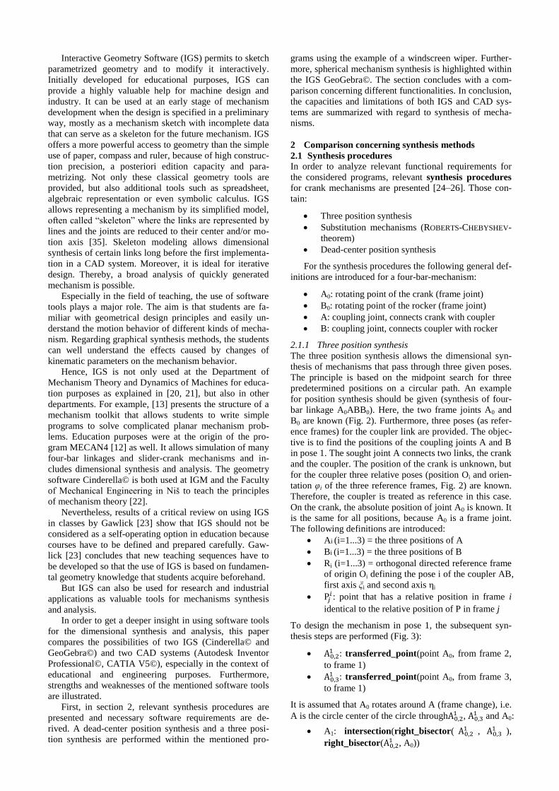
In the first example a convertible roof mechanism is
treated, in the second example a roof support is considered
which allows straight line guidance. Besides, the applica-
tion of graphical methods for kinematic dimensioning, a
geometry-based power analysis is implemented, so that
driving and joint forces are represented in the form of
position-dependent force vectors.
As the previous mentioned comparative works [27, 28]
showed that GeoGebra exceeds the possibilities of Cin-
derella, GeoGebra will be used in this paper to develop an
interactive worksheet for the dimensional synthesis of a
windscreen wiper. Such an interactive worksheet is pre-
sented in Fig. 6. It offers the following adjustments:
Angle positions of the left and right wiper blades
– blue: position one (1), green: position three (3)
Link lengths (wiper blades, coupler, distance be-
tween the two frame joints)
Attack angle γ of the wiper blades
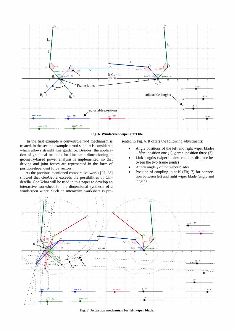
Position of coupling joint K (Fig. 7) for connec-
tion between left and right wiper blade (angle and
length)
Fig. 7. Actuation mechanism for left wiper blade.
1
2 3
K1
Aa A0
1 1
3
3
Ba
adjustable positions
adjustable lenghts
Frame joints ψ
Bi
γ
Fig. 6. Windscreen wiper start file.
1 1
3
3
Ba
adjustable positions
adjustable lenghts
Frame joints ψ
Bi
γ B0
C0 l3
B0C0 = l4
l3
lw
lw
l
5
l5
l4

Fig. 8. Final windscreen wiper mechanism (GeoGebra©).
First, for this task, the four-bar linkage to actuate the
left wiper blade is sought (missing: coupler and crank
length, position of crank frame joint A0). The inner and
outer dead-center positions, i.e. the swinging angle ψ and
the rocker length (l3), the time ratio between forward and
backward motion (corresponds to crank angle φH) and the
eccentricity e are given in the starting file. Fig. 7 shows
the resulting mechanism by applying the dead-center
position synthesis. In this figure the blades are already
sketched in position two, necessary for the further synthe-
sis.
Second, for this task, the two-bar connection between
left and right wiper blade is sought. Here, the lengths of
both links have to be defined. The problem is solved by
applying the three position synthesis. From the left blade
three poses of the coupling joint K are known, whereas
from the right blade three positions are known (Fig. 7).
The final movable mechanism is shown in Fig. 8 (brown).
The same dimensional synthesis can be performed in
Cinderella©. As already mentioned, the dimensional syn-
thesis with GeoGebra© is more user-friendly than those
with Cinderella©. Additional functionalities and tools in
GeoGebra© compared to Cinderella© that facilitate the
work are the following:
Quick transfer of angles (parametrization, “rota-
tion” tool)
Easy parametrization of the models through slid-
ers (Fig. 6)
Display of all geometrical objects in algebraic
equations (e.g. coordinates, equations)
Integration of dependencies (e.g. value of eccen-
tricity (e))
Free labeling of construction/geometric elements
Easy fade-out of non-required geometric ele-
ments (amongst other definition of help objects)
Mouse zoom- and pan-functions
Fig. 9. Parametrization in Cinderella© (left) and
GeoGebra© (right).
Fig. 10. Angle transfer in GeoGebra©.
Fig. 11 Angle transfer in Cinderella©.
Three functionalities should be described in more de-
tail to understand the differences better. First of all, in
GeoGebra© only one operation is used to parametrize
parameters (slider tool) (Fig. 9 (right). All properties can
be defined in the pop-up window. In Cinderella© no spe-
cific tool is available. Starting from a point, a straight line
- perpendicular to an axis - is drawn (Fig. 9 (left)). A sec-
ond point is defined on this line (movable). Then, the line
is faded out and the two points are connected by a line
segment. Hence, in total of four operations are necessary
to define a slider with Cinderella, whereas only one is
necessary with GeoGebra©).
Angles are transferred easily in GeoGebra©. There
are two options (cf. Fig. 10): Using the angle transfer tool
(fixed value) needs two operations. First, a point is rotated
around a center and then the second leg is drawn. Second,
the rotating tool can rotate a selected line directly around a
point.
Angle transfer is more complicated in Cinderella©.
The procedure is shown in Fig. 11. First, a circle with
fixed radius K1 is sketched around the reference rotating
point Oref. The intersection of this circle with the legs
provides two points P1 and P2 (needed as construction
points). Then, the compass tool is used to transfer the
circle K1 to the new rotating point O*. The intersection
with the leg l gives the new first construction point (P1*).
This is the center of circle K2, transferred from the refer-
ence figure as well. Intersection of circle K1 and K2 gives
the second construction point P2*. A half-line starting
from the new rotation point O* through the second con-
struction point P2* defines the second leg (dashed-line). In
total this procedure requires eight operations.
As position synthesis is based on midpoint search,
perpendicular bisectors are used for classical mechanism
synthesis on paper. In GeoGebra© there is a tool that is
able to directly draw perpendicular bisectors between two
points. If this operation is performed twice, the intersec-
tion of both perpendicular bisectors defines the center of
the circle through the three points. Here, in total, three
operations are required. Cinderella© has no tool for per-
pendicular bisectors. Therefore, the design procedure is as
follows:
Connecting two points
Find midpoint between those points
Draw perpendicular line through this midpoint
The mentioned steps are performed twice. The intersec-
tion of both perpendicular lines gives the midpoint. So
there are seven operations in total.
movable mechanism

Fig. 12. Transferring points from one reference frame to
other reference frames
But it is not necessary in IGS to follow the classical
approach. In GeoGebra© and Cinderella© a tool is pro-
vided to find the circle through three given points and to
define the center of that circle. This requires only two
operations. Points are transferred using the compass tool
twice. This is the same for GeoGebra© and Cinderella©.
The procedure (as described in section 2.1.1) is shown in
Fig. 12. Instead of drawing circles for the point transfer,
reference angles can be used.
2.2.2 Synthesis with CAD systems
In order to demonstrate and better visualize the synthesis
procedure, the dimensions of the mechanism are scaled.
Fig. 9 shows such a mechanism in Autodesk Inventor©
with appropriate dimensions. To find appropriate dimen-
sions and design such a mechanism, the mentioned graph-
ical synthesis method can also be implemented in a CAD
program. As an example, Lonij et al. [30] show this ap-
proach on the basis of a bottle-handling mechanism using
the CAD system Autodesk Inventor Professional 2012©.
For each synthesis step separate models are created which
are later combined to an assembly. By using parametriza-
tion, changes in initial parameters can be easily transferred
to the dimensions of the final model. In this case, design
rules are used for optimization of the mechanism (iLogic
feature of Autodesk Inventor©). The focus lies on a lim-
ited number of parameters whilst compliance with the
predefined requirements is guaranteed. The user can di-
rectly observe the influence of parameter changes with
respect to performance properties.
Another example for including graphical position syn-
thesis and analysis steps for mechanism development in
CAD systems is shown in [31]. The example here is the
opening and closing mechanism of a skylight dome.
More generally, Scherer et al. [32] analyze different
possibilities to transfer mechanism problems which re-
quire graphical synthesis procedures into CAD systems,
including Catia V5© and Pro/Engineer Wildfire©. The
results show that in general, the integration of graphical
synthesis according to VDI guidelines is possible even if
design problems due to various CAD functionalities could
occur. They conclude that graphical synthesis procedures
for mechanism design will still be important in the future.
CAD systems may become natural tools for mechanism
synthesis, as they are capable to represent 3D multibody
assemblies and offer numerous ways to parametrize them.
Moreover, further analysis tools are available within CAD
software, e.g. installation space/workspace analyses, colli-
sion analyses or, as mentioned before, kinetostatic analy-
sis modules.
The aim of the following work is to perform the dead-
center position synthesis and the three position synthesis
for the windscreen wiper in CAD systems as well. The
synthesis procedure is shown below with CATIA V5©.
Fig. 13. Windscreen wiper mechanism with appropriate
dimensions (built in Autodesk Inventor©).
The initial position of the wiper blades is defined by
using reference planes in the 3D assembly mode. For this,
a new part has to be defined as skeleton part. If the orien-
tation angles of those planes are defined as global parame-
ters, they can be changed easily afterwards. Fig. 14 shows
the two poses of the left wiper blade.
A new part is inserted for the dead-center position syn-
thesis. Within the sketch mode, the positions of the rocker,
points Ba and Bi, can be projected in the sketch plane.
Then, the dead-center position synthesis can be performed
almost like in IGS. By using the snapping tool, perpendic-
ular or parallel axes can be drawn.
Finally, to find crank and coupler lengths, the eccen-
tricity (e) (previously defined as global parameter) is
sketched from the straight line through Ba and Bi. The
intersection with the outer circle results in the position of
A0. By connecting A0 with Ba, the position of A in the
outer dead-center position is found.
The lengths of crank (l1) and coupler (l2) are measured
and the measured values are kept. The lengths are defined
as parameters in the skeleton part and have to be pub-
lished to be used in other parts. Moreover, the point A0 is
defined as an output feature. By doing so, the parts crank
and coupler can be linked to the synthesized lengths (see
Fig. 15). An axis through A0 and perpendicular to the
wiper plane defines the revolute joint axis of the frame
joint A0. For the right side of the windscreen mechanism
(Fig. 16), the three positions of the blades are sketched in
the skeleton model and published (also depending on
global parameters). Then, a new part is created for the
three position synthesis.
Fig. 14. Dead-center position synthesis (CATIA© sketch
mode).
Ba Aa A0 Bi
e

Fig. 15. Final mechanism for left wiper blade.
The positions of joint K are projected in the sketch
plane and are transferred to the reference position (here
position 1, blue wiper). This is done by first measuring the
distances between point K2 and R2 and K2 and C0 and then
by linking those distances to the triangle R1, C0, K21 .
In CAD systems, it is not necessary to draw perpen-
dicular bisectors to find the midpoint of the circle passing
through the three transferred points, because a tool for
finding a circle based on three points is available (in con-
trast to IGS including the definition of the midpoint). So,
the point C1 is defined and the lengths of the two-bar link-
age connecting left and right wiper blade are determined.
As before, the measured lengths have to be published and
re-used (by inter-part reference link) within the respective
parts. The movable mechanism can be designed.
The entire dimensional synthesis procedure in CAT-
IA© is not as intuitive as in GeoGebra©. CATIA© is less
tolerant concerning mistakes. The designer has to consider
the synthesis steps precisely, decide which points have to
be published and choose the right references. Otherwise,
the mechanism will not be adaptable later.
The entire mechanism can be designed in Autodesk
Inventor© using the sketching tool as well. Due to limited
space, the synthesis procedure in this software is omitted
here. But a proper built windscreen wiper mechanism is
shown in Fig. 13. For additional information, in [30] a
detailed description of the interactive design of opening
and closing mechanisms for skylight domes based on
synthesis methods using Autodesk Inventor© is presented.
Fig. 16. Three position synthesis in sketch mode (CATIA©).
To conclude, compared to Autodesk Inventor©,
CATIA© has the following disadvantages with regard to
dimensional synthesis procedures:
Time-consuming publishing of parameters
Time-consuming definition of output features
No possibility to define lines with same length
without measurement (cf. [32])
No possibility to create points, straight lines and
planes in assembly mode
Defining parameters is similar in CATIA© and Inventor©.
But one drawback of CATIA© concerning synthesis is the
fact that geometric objects (such as points) have to be
published to be globally used. In Inventor© this step is not
required.
2.3 Mechanism synthesis for spherical mechanisms
Examples for synthesizing spherical or even spatial mech-
anisms with special developed software can be found in
[33] or [34]. In these cases, the software GECKO is used.
But spherical mechanism synthesis is also possible by
using GeoGebra©. Fig. 17 - Fig. 19 show two examples.
In Fig. 17 a spherical mechanism synthesis is per-
formed. The method for three position synthesis for planar
mechanisms can be easily adapted to spherical mecha-
nisms. But in contrast to the procedure described in sec-
tion 2.1.1., in this example, three poses of the coupler (1-
3, joints A and B) are given and the frame joints of crank
(A0) and rocker (B0) are sought. This is an example for a
spherical tow coupling, described in detail in [34].
Spherical mechanisms have one center point O and the
circular trajectories are located on concentric spherical
surfaces S centered on that point. To design the mecha-
nism (here to find joint A0), the following synthesis steps
are performed:
Construct circular segment (A1, A2) = segment
[A1,A2]
Construct circular segment (A2, A3) = segment
[A2,A3]
Construct perpendicular circle (A1, A2) =
right_circle(center O, equidistant to A1, A2) = C1
Construct perpendicular circle (A2, A3) =
right_circle(center O, equidistant to A2, A3) = C2
Construct point A0: intersection(C1, C2)
Fig. 17. Spherical three position synthesis – procedure.
K1
K2
K3
K31
K21
C1
C0
R1
R2 R3
A2 O
A0
A3
A1
C1
C2

Fig. 18. Spherical mechanism synthesis (GeoGebra©).
The circles C1 and C2 correspond to the perpendicular
bisectors. The intersection of both circles is the sought
point A0, equidistant to A1, A2 and A3. The synthesis pro-
cedure is the same to find the position of point B0, equi-
distant to B1, B2 and B3. The resulting mechanism is
shown with a bold line in Fig. 18.
In Fig. 19 the ROBERTS-CHEBYSHEV-theorem for a
given spherical four-bar mechanism (blue) - moving on
sphere S - is executed allowing to find two further four-
bar linkages (red, green) that can generate the same cou-
pler curve. Again, the synthesis procedure can be derived
from the methods described in section 2.1.2 for planar
mechanisms. It is for the first mechanism ((*) -
A0A*B*B0*):
Point A*
= so that A0A*KA is a spherical parallelogram
= circle D1: intersection(sphere(center K, radius
A0A),S)
= circle D2: intersection(sphere(center A0, radius
AK),S)
= Construct point A*: intersection(D1,D2)
Point B*
= so that projection of triangle (A*B*K) is homo-
thetic to projection of triangle (AKB) in this order
= circle D3: intersection(sphere(center A*, radius
AK⋅A*K / AB), S)
Fig. 19. Spherical ROBERTS-CHEBYSHEV-theorem.
= circle D4: intersection(sphere(center K, radius
BK ⋅A*K / AB), S)
= Construct point B*: intersection(D3,D4)
Point B0*
= so that projection of triangle (A0B0*B0) is ho-
mothetic to projection of triangle (AKB) in this
order
= circle D5: intersection(sphere(center A0, radius
AK⋅A0B0 / AB), S)
= circle D6: intersection(sphere(center B0, radius
BK⋅A0B0 / AB), S)
= Construct point B0*: intersection(D5,D6)
A similar procedure can be derived for the second
mechanism ((**) - A0**A**B**B0).
In summary, necessary design functionalities for
spherical mechanisms are:
Create spheres
Perform Boolean operations, such as intersec-
tions
Draw circular arcs
Draw circles
Use link length ratios to generate similar trian-
gles (for ROBERTS-CHEBYSHEV-theorem)
GeoGebra© offers the possibility to display both, a 3D
and a 2D window, the latter proving particularly useful for
displaying sliders of the different parameters. Further-
more, 2D and 3D geometrical construction elements can
be used within the same file.
2.4 Comparison
To compare the presented IGS and CAD tools with re-
spect to the required time for mechanism synthesis and
offered functionalities, the number of necessary operations
for different tasks is listed in Tab. 1. Those tasks include:
parametrization, angles and lengths transfer, perpendicular
bisector sketching and finding the rotating point based on
three points lying on a circular path. The number of re-
quired operations to draw parallel lines, to find intersec-
tion points or to draw circles/straight lines through given
points does not vary in different programs. Therefore,
these functionalities are not considered for comparison.
Mechanism synthesis in Cinderella© takes much long-
er compared to mechanism synthesis in GeoGebra©, be-
cause angle transfer, parametrization and bisector sketch-
ing extend the procedure time. It is worth mentioning that
the 3D interface in GeoGebra© is a good and functional
tool for spherical mechanism synthesis.
Par
amet
rize
Tra
nsf
er a
ng
les
Tra
nsf
er l
eng
ths
Dra
w p
erp
en-
dic
ula
r b
isec
tors
Fin
d r
ota
tin
g
po
int
(po
siti
on
syn
thes
is)
Cinderella© 4 8 1 7 2
GeoGebra© 1 1 (2) 1 3 2
CATIA© 1(*)
3 3 - 1
Inventor© 1 1 1 - 1 (*) here step “publishing” is not included
Tab. 1. Required number of operations for different tasks.
coupler
curve
A
B
A0
B0
1
2
3

However, still a few useful functionalities are missing.
For example it would be a strong advantage if the trace of
a point generated by motion in GeoGebra© could be
stored in a permanent parametrized way, instead of being
regenerated for each change of the mechanism.
The approach for mechanism synthesis using the
sketch mode within CAD systems is similar for CATIA©
and Autodesk Inventor©. But angle and length transfer is
more complicated in CATIA© because angles or lengths
have to be measured first. Furthermore, publishing param-
eters and defining output features extend the procedure
compared to Autodesk Inventor© where all parameters
and construction elements can be directly globally used.
In general, CAD software provides extended capacities
with respect to IGS (constraint solver, detailed 3D repre-
sentation of parts), but requires more time for mechanism
synthesis because of the complex interface. Besides, CAD
software is less tolerant concerning mistakes within the
design process. The engineer has to consider the synthesis
steps precisely and has to choose the right references.
Otherwise, the mechanism will not be adaptable later.
Furthermore, dedicated tools for synthesis are not provid-
ed (e.g. displaying coupler curves).
In general, synthesis within a CAD system should be
done after being familiar with mechanism theory and the
implementation in an IGS, which is more intuitive than
CAD. This is due to the fact that, in general, CAD systems
were developed for detailed design more than for dimen-
sional synthesis procedures. They require many details
that are not useful for graphical synthesis methods and
distract the designer from the task. For instance, skeletons
are complex to build and the 2D synthesis procedures
must be extended to 3D, although it is pointless most of
the time. But once a deep knowledge of mechanism de-
sign is obtained, mechanism synthesis within CAD sys-
tems enables the engineer to interactively adapt mecha-
nisms in order to optimize them. The results of changing
parameters can be directly seen and the understanding of
the motion behavior of the mechanism is enhanced.
3 Conclusion
In this paper the possibilities of two Interactive Geometry
Software sketchers (IGS) (Cinderella©, GeoGebra©) and
two CAD systems (Inventor Professional©, CATIA V5©)
were compared. Relevant synthesis procedures were pre-
sented and explained in detail: three position synthesis,
dead-center position synthesis and ROBERTS-CHEBYSHEV-
theorem. All of them were reformulated as algorithms
comprising a sequence of geometric operators. The algo-
rithms were tested on the mentioned software types.
Moreover, different synthesis examples were shown: a
planar windscreen wiper and a spherical four-bar linkage.
Based on these examples, necessary functionalities that
software tools should provide were derived.
Although both types of software are capable to process
the synthesis algorithms, the IGS appeared particularly
efficient for fast, preliminary synthesis of linkages. Fur-
thermore, the spherical mechanism could be easily treated
with an IGS (GeoGebra©), thus showing the major inter-
est of this category of software for mechanism dimension-
al synthesis.
Future CAD software should develop easier sketchers
for mechanism synthesis, encouraging the use of mecha-
nism skeletons and avoiding distracting the designer with
useless details at this preliminary stage of the design pro-
cess. For the moment, synthesis methods are lying in the
designer’s mind more than in the software, and many
enhancements should be expected in the years to come.
Acknowledgment
The authors acknowledge the funding of this work by the
Laboratory of Excellence Innovative Mobility: Smart and
Sustainable Solutions (LabEx IMobS³) and the French
Institute for Advanced Mechanics (IFMA).
References
[1] VDI 2123 - Plain linkages - Design of four-bar
linkages favourable for transference for oscillatory
motion in the same direction, 2123, 2008.
[2] VDI 2124 - Plain linkages; design of four-bar
linkages favourable for transference for oscillatory
motions in opposite directions, 2124, 1959.
[3] VDI 2125 - Planar mechanisms - Transfer of a
slider motion into a rocker motion with regard to
optimum transmission angle, 2125, 2014.
[4] VDI 2126 - Plain linkages; design of thrust cranks
favourable for transfer; conversion of oscilatory
motions to translatory motions, 2126, 1959.
[5] VDI 2130 - Crank and rocker mechanisms; design
and computation in four-link planar linkages, 2130,
1984.
[6] M. Hohenwarter, GeoGebra, www.geogebra.org,
2005.
[7] J. Richter-Gebert, Cinderella. Die interaktive Ge-
ometrie-Software, www.cinderella.de/tiki-
index.php, 2005.
[8] ARTAS - Engineering Software, SAM,
www.artas.nl/de/sam, 1990.
[9] R. Braune, GENESYS, www.ifg.uni-
hannover.de/genesys.html, 1990.
[10] IGM - Institut für Getriebetechnik und Maschi-
nendynamik, GECKO, www.igm.rwth-aachen.de,
2000.
[11] KISSsoft AG, Kissoft, www.kisssoft.ch, 1998.
[12] V. Petuya, M. Diez, C. Pinto, and A. Hernández,
“An educational software for the analysis and syn-
thesis of planar four bar linkages,” in Proceedings
12. World Congress in Mechanisms and Machine
Science
[13] H. H. Cheng and D. T. Trang, “Object-oriented
interactive mechanism design and analysis,” Engi-
neering with Computers, vol. 21, no. 3, pp. 237–
246, 2006.
[14] Dassault Systèmes, CATIA V5, www.3ds.com,
2014.
[15] Autodesk, Autodesk Inventor, www.autodesk.de,
2014.
[16] PTC, Creo, www.ptc.com/products/creo, 2009.
[17] SolidWorks, SolidWorks, www.solidworks.de,
1997.
[18] MSC - The MacNeal-Schwendler Corporation,
ADAMS, www.mscsoftware.com/product/adams,
2014.
[19] Siemens, LMS Virtual.Lab Motion,
www.plm.automation.siemens.com/en_us/products
/lms/virtual-lab/motion/, 2015.

[20] B. Corves, “Computer-aided Lectures and Exercis-
es: Graphical Analysis and Synthesis in Mecha-
nism Theory,” in Proceedings of the 11th World
Congress in Mechanism and Machine Science:
China Machine Press, 2004.
[21] S. Kurtenbach, T. Mannheim, M. Hüsing, and B.
Corves, “Content and Realization of Mechanism
Theory at RWTH Aachen University,” in ISEMMS
2013, 2013, pp. 39–46.
[22] N. D. Pavlović, M. Milošević, Milojević, and An-
drija, “COMPUTER-AIDED GRAPHICAL
ANALYSIS AND SYNTHESIS OF MECHA-
NISMS,” Belgrade, Serbia, 2010.
[23] T. Gawlick, “On Dynamic Geometry Software in
the regular classroom,” Zentralblatt für Didaktik
der Mathematik, vol. 34, no. 3, pp. 85–92, 2002.
[24] J. J. Uicker, G. R. Pennock, and J. E. Shigley,
Theory of machines and mechanisms, 4th ed. Ox-
ford: Oxford University Press, 2011.
[25] J. M. McCarthy and G. S. Soh, Geometric design
of linkages, 2nd ed. New York: Springer, 2011.
[26] A. K. Mallik, A. Ghosh, and G. Dittrich, Kinematic
analysis and synthesis of mechanisms. Boca Raton
[etc.]: CRC Press, D.L. 1994.
[27] I. Prause, S. Kurtenbach, C. Weigel, M. Hüsing,
and B. Corves, “Vergleich von dynamisch-
interaktiver Geometriesoftware für die Masssyn-
these von ebenen Getrieben,” in 10. Kolloquium
Getriebetechnik 2013, pp. 39–56.
[28] S. Kurtenbach, I. Prause, C. Weigel, and B. Corves,
“Comparison of Geometry Software for the Syn-
thesis and Analysis in Mechanism Theory,” in
ISEMMS 2013, 2013, pp. 193–202.
[29] B. Corves, M. Riedel, and M. Hüsing, “Descriptive
and Intuitive Mechanism Design and Synthesis Us-
ing GeometryBased Computer-Aided Methods,” in
13th World Congress in Mechanism and Machine
Science, 2011.
[30] G. Lonij, S. Kurtenbach, M. Hüsing, and B. Corves,
“Interactive Design of Opening and Closing Mech-
anisms for Skylight Domes,” in EUCOMES 2012,
Santander, Spain, 2012, pp. 227–235.
[31] B. Corves, G. Lonij, and S. Kurtenbach, “Parame-
ter-Driven Mechanism Synthesis in CAD,” in IN-
TERNATIONAL DESIGN CONFERENCE, 2012,
pp. 523–532.
[32] T. Scherer, C. Ahl, W. Lohr, and R. Lohe, “Ein-
satzmöglichkeiten der 3D-CAD Systeme Catia V5
und Pro/Engineer Wildfire in der Getriebetechnik,”
in 9. Kolloquium Getriebetechnik: Universitätsver-
lag Chemnitz, 2011.
[33] G. Lonij, S.-W. Choi, and B. Corves, “Interactive
design of a robotic gripper system with the geome-
try program „GECKO“,” in Proceedings of the 5th
International Conference on Computational Kine-
matics, Berlin Heidelberg: Springer, 2009, pp.
225–232.
[34] G. Lonij, M. Hüsing, S.-W. Choi, and B. Corves,
“Development of a spherical linkage mechanism
with the aid of the dynamic spatial geometry pro-
gram “GECKO”,” in EUCOMES 2008
[35] J.-C. Fauroux, M. Sartor, and M. Paredes. “Using
the Skeleton Method to Define a Preliminary Geo-
metrical Model for Three-Dimensional Speed Re-
ducers”, in Engineering with Computers, Springer-
Verlag, vol. 16, no. 2, pp. 117-130, 2000, ISSN
0177-0667.