Embed Size (px)
Citation preview

“Using High Performance Multiplexer Technology to Improve Your HF Station
Capability”
by Andrei Fedorishchev
RA6LBS

Agenda
▪ A bit of history ▪ What is a multiplexer? ▪ Can I fry my radios? ▪ Specifications of multiplexers ▪ Why do we need additional filters? ▪ Multiplexer + Filter combo ▪ Relay switches ▪ Where is the right place for filters and a switch? ▪ The devil is in the details … ▪ Interconnecting cables ▪ Some examples and ideas for transmit antennas ▪ Upside down! ▪ Can we have any benefits for receive antennas distribution? ▪ Q & A?
A bit of history:
P33W, WRTC-2010 and Multiplexers
We implemented and used with great success an In-Band style of operation at P33W in 2008: WPX SSB, IARU, and latter WW contests.
After IARU-2008, which we won of course, Harry - RA3AUU asked me if I could suggest something innovative for Russian teams, in order to win WRTC-2010 in Moscow.
Inspired by P33W success with InBand, I was confident that the only place to improve the proposed WRTC setup would be a better utilization of TriBander on 14-28.
And no one could answer my question WHY don’t we have same thing as Duplexers at VHF …

The very first HF triplexer, circa November 2008

What is a multiplexer?
▪ Used for decades by VHF–UHF guys!
▪ Multiplexers enable multi-transceiver stations to share a single multi-band antenna;
▪ Multiplexers, by themselves, cannot provide the necessary isolation with 100W radios;
▪ Each transmitter must be connected to a multiplexer through a bandpass filter in order to keep them from interfering with each other;

How does it work?
▪ It`s a filter!
▪ Think of a triplexer as a low pass filter, a bandpass filter and a high pass filter with their outputs connected;
▪ Triplexer is routing high, mid and low frequencies to three different input ports;
Can I fry my radios?
▪ YES!
▪ and NO! ▪ Hardware band switching lockout is a must!
▪ Power consideration is a must!
▪ All of this is easy to implement and to control.

Part I
Components of multiplexing technology

Multiplexers vs Antennas
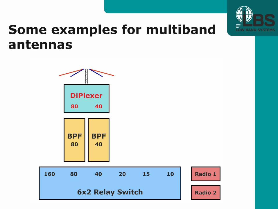
Di- Duo band antennas, simple dipoles feed in parallel with single coax
160/80, or 80/40, or 40/20 or …… some exotics like 6/4 in Europe
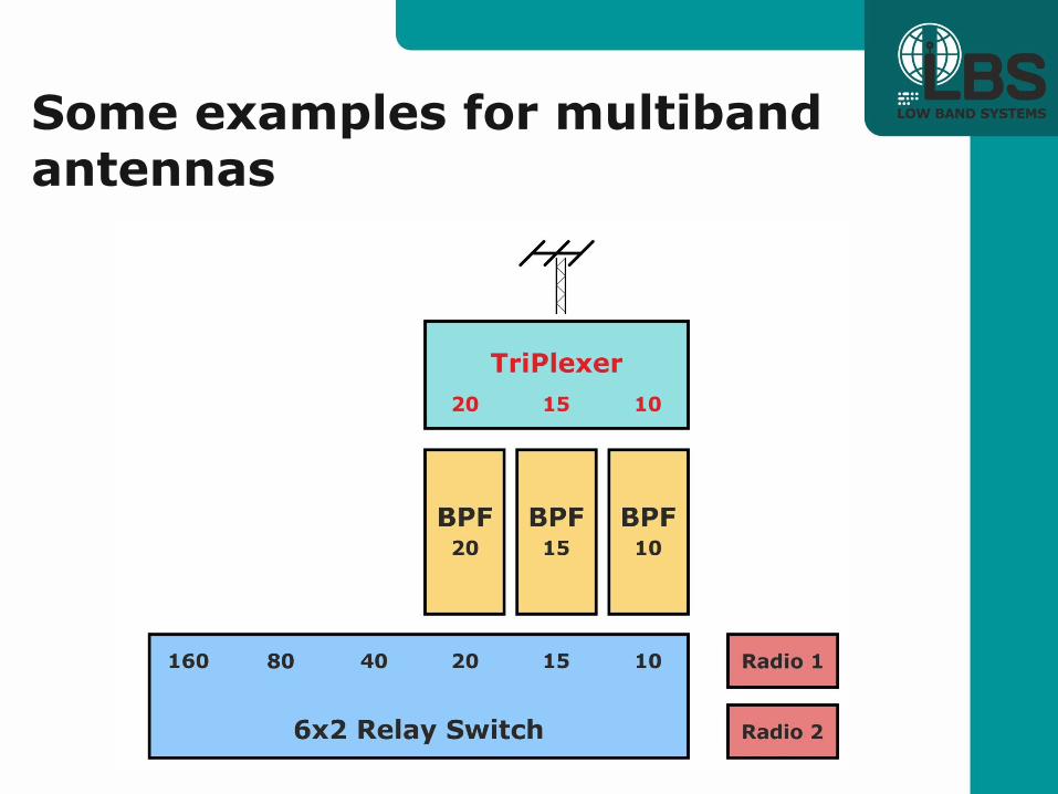
Tri- Tribander gives three bands usually 20-15-10 Quad- 4band antennas, like OptiBeam OB12-4 and multiband Verticals! 40-20-15-10 Penta-5/6 band antennas like Spiderbeam, Hexbeams and multiband Verticals! 20-17-15-12-10-6

Specifications of multiplexers
#1 - Losses Fractions of Decibel, typical average is ≤ –0,2db.
14Mhz: -0,15db.
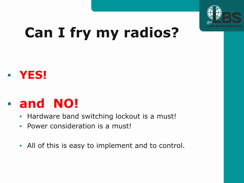
Specifications of multiplexers
#1 - Losses
Decibel is a ratio of Input to Output Power
(dB) = 10 log(Pout/Pin) Multiplexer`s
Attenuation, db.
Transmitted
power at
1500W TX Out
Transmitted
power at
100W TX Out
-0,1 1465 98
-0,2 1432 95
-0,3 1399 93
-0,4 1368 91
-0,5 1336 89
-0,6 1306 87
-0,7 1276 85
-0,8 1247 83
-0,9 1219 81
-1,0 1191 79

Specifications of multiplexers
#1 - Losses This is not a question of useful power losses, but more of heat dissipation!
Fortunately, this heat
is spread
among few
of the plexer`s
components.
Multiplexer`s
Attenuation,
db.
1500W TX
Heat generation,
Watts
100W TX
Heat generation,
Watts
-0,1 35 2
-0,2 68 5
-0,3 101 7
-0,4 132 9
-0,5 163 11
-0,6 194 13
-0,7 224 15
-0,8 253 17
-0,9 281 19
-1,0 309 21
Specifications of multiplexers
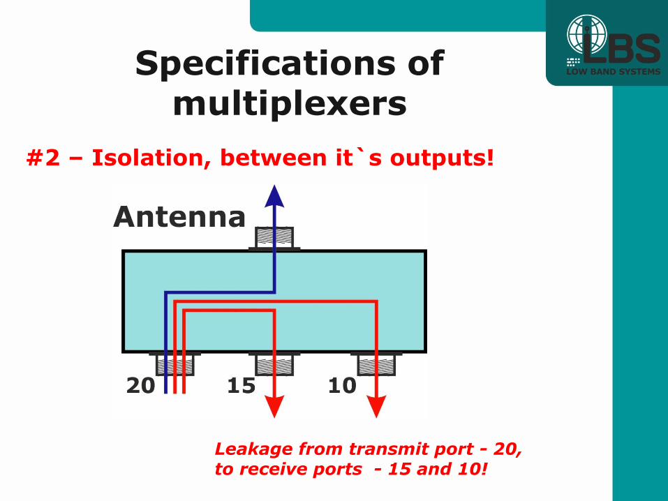
#2 – Isolation, between it`s outputs!
Leakage from transmit port - 20, to receive ports - 15 and 10!
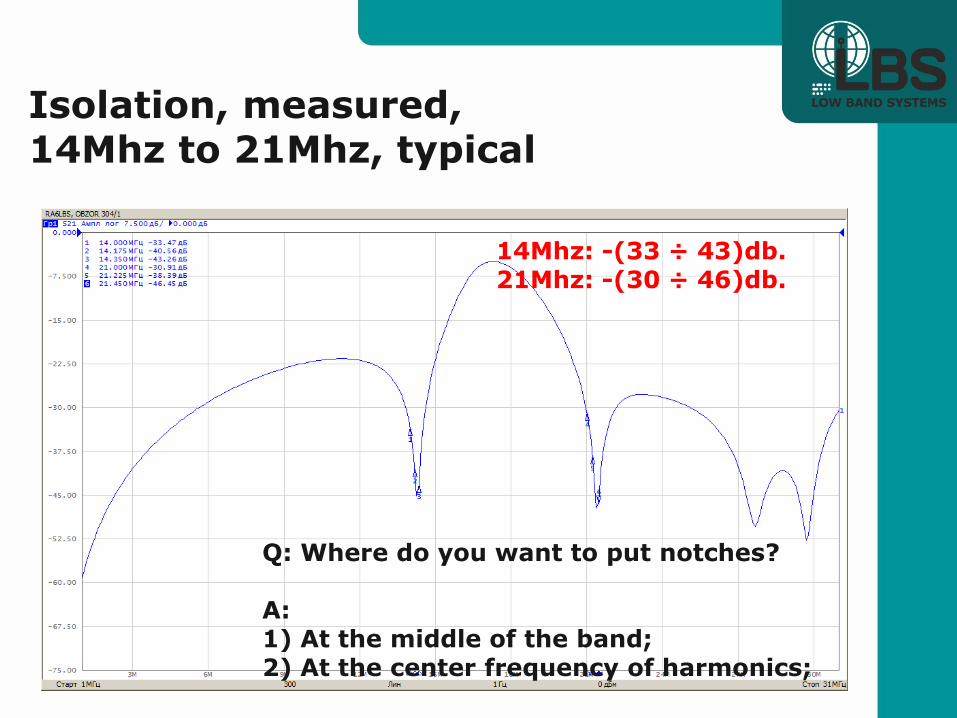
Isolation, measured, 14Mhz to 21Mhz, typical
Q: Where do you want to put notches? A: 1) At the middle of the band; 2) At the center frequency of harmonics;
14Mhz: -(33 ÷ 43)db. 21Mhz: -(30 ÷ 46)db.

Isolation, measured, 14Mhz to 28Mhz, typical
`
Where do you want to put notches?
14: -(39 ÷ 44)db. 28: -(33 ÷ 39)db.

Specifications of multiplexers
#2 - Isolation between its outputs!
Isolation 1500W TX, Leakage power
100W TX, Leakage power
-10 db. 150W 10W
-20 db. 15W 1W
-30 db. 1,5W 0,1W
-40 db. 0,15W 0,01W
-50 db. 0,015W 0,001W

Why do we need ISOLATION?
2 issues:
▪ Safety: Unknown, and different level of damage to different radios
▪ Interference: Starting figures at around +10dbm may be,
but again differs by radios and some other factors

How many decibels of isolation do we need?
▪ Think of DX pedition utilizing 2 or 3 or 4 station at the same time? When sum of QRM from this multiple radios is going into play?
▪ And what is the criteria of “QRM free” operation? ▪ Harmonics level? – NO ▪ No any other signs of station transmission? - YES ▪ Different band combination - different isolation requirements? Think of 10 meters noise level vs 80 meters …
We have now, 8 YEARS OF EXPERIENCE with 100 – 4500W power levels, different Rigs and Ops; Observation: –(80÷100) db. should be fine for almost any condition.
Target figure is -90 db. of isolation for the complete system
Neither the Triplexer alone, nor the band pass filters available in 2008 on the market, was close to this figure.
Best of the market, W3NQN design filters, has been modified with extra rejection sections, to satisfy tougher requirements.
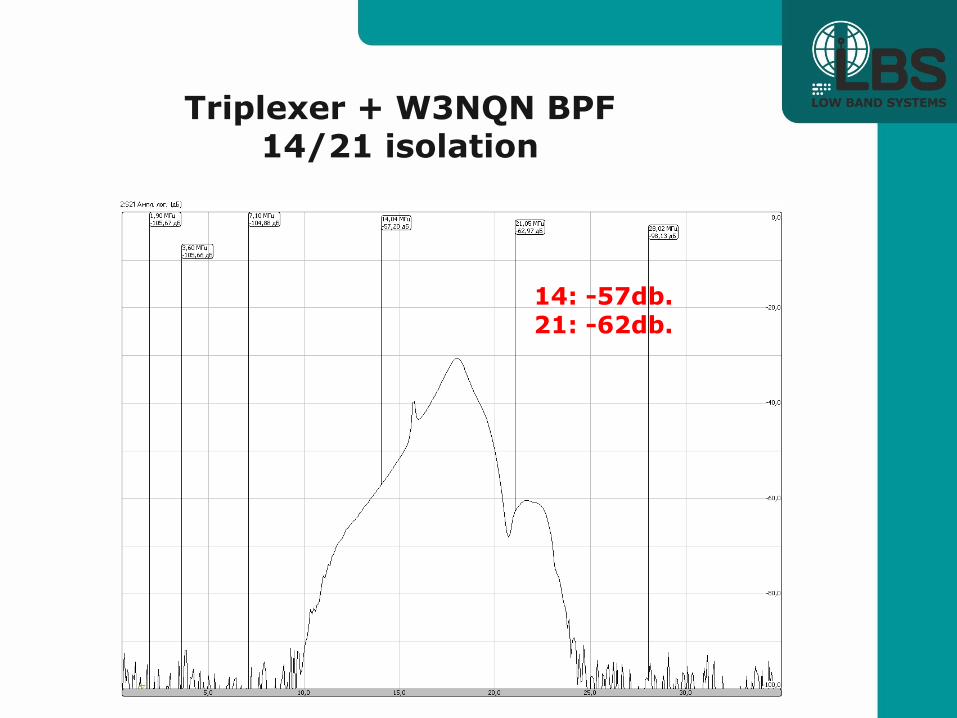
Triplexer + W3NQN BPF 14/21 isolation
14: -57db. 21: -62db.

Triplexer + modified W3NQN filter, 14/21 isolation:
14: -96db. 21: -103db. 40 db. improvement !

Triplexer + PerfoBox filters, 1500W series,
14/21 isolation:
14: -94db. 21: -88db.

Quadplexer + PerfoBox filters, 1500W series,
7/21 isolation:
7: -95db. 21: -101db.

Interconnecting Cables
▪ Shielding Effectiveness: ▪ Messi & Paoloni >105db.
▪ Andrew LMR-240 >90db.
That’s good enough.
▪ Connectors! Should always be clean and tighten well!
Soldered cables braid to the body of connector!
Bad connectors easily destroys low loss path;

Relay switches:
▪ KK1L – entry level switch ▪ - (85÷64)db. isolation, best case,
not enough for this task
▪ RK-226 – good choise ▪ - (90÷80)db. isolation, typical,
(due to extra relay)
▪ Matrix switches – best of the best ▪ - (125÷95)db. Isolation, typical
▪ And any power levels!

Matrix switch, best of the best
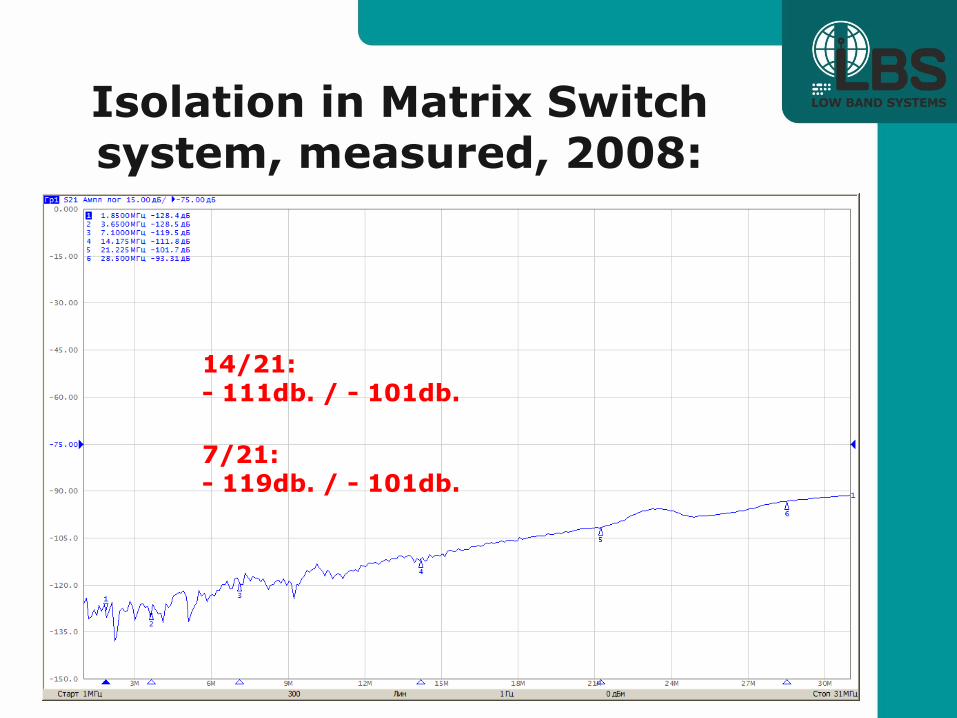
Isolation in Matrix Switch system, measured, 2008:
14/21: - 111db. / - 101db.
7/21: - 119db. / - 101db.

Multiplexer + Filter + Relay switch Combos

Classic, 2x6 switch combo:
Great if it would be like this:

Classic, 2x6 switch combo:
▪ Leakage is determined by the switch!
▪ Not enough isolation in the switch can destroy performance of the best filters and Triplexer!
Classic, 2x6 switch combo:

Classic, 2x6 switch combo:

with KK1L relay switch
Развязка 2 варианта
14: -62db. 28: -56db.
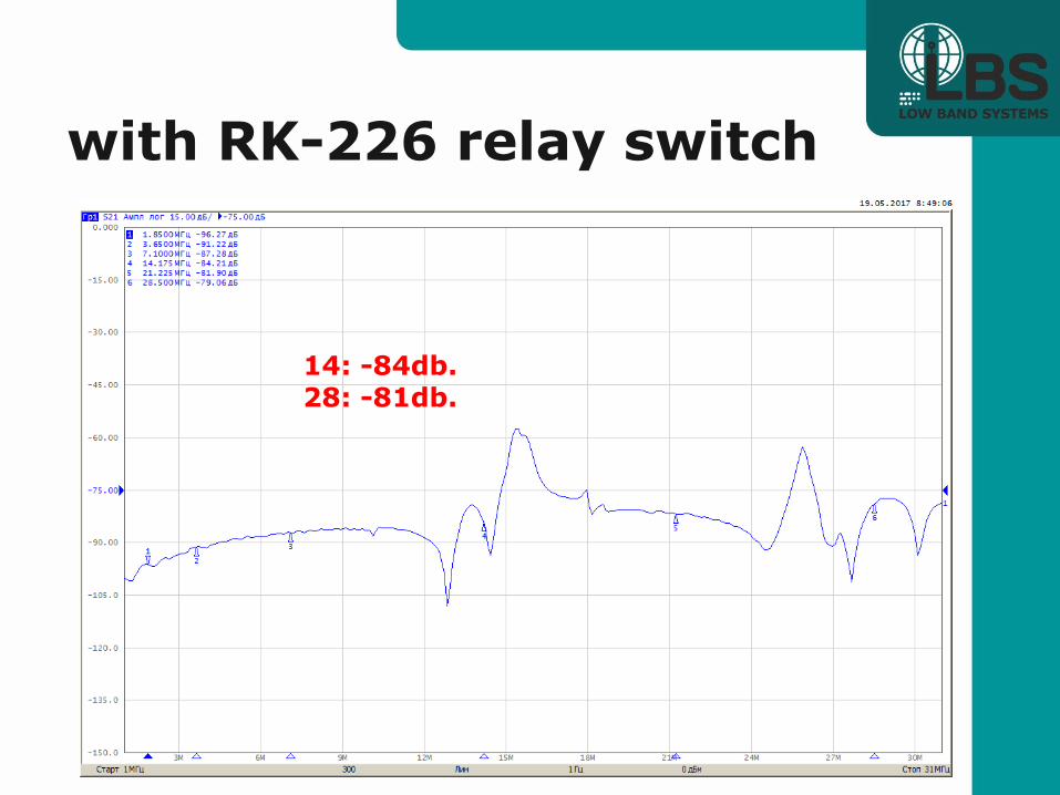
with RK-226 relay switch
14: -84db. 28: -81db.
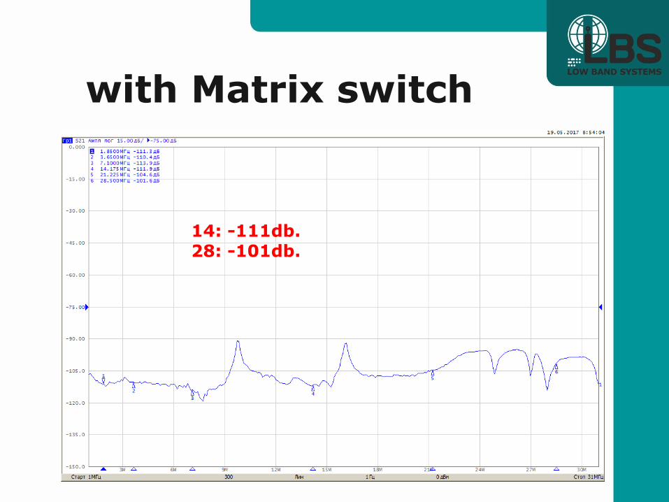
with Matrix switch
14: -111db. 28: -101db.

Where is the BEST place for the filters and a switch?
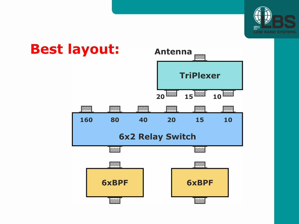
Best layout:
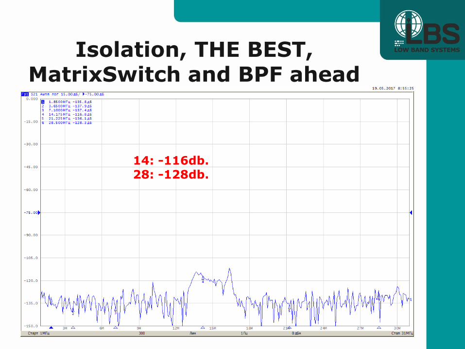
Isolation, THE BEST, MatrixSwitch and BPF ahead
14: -116db. 28: -128db.
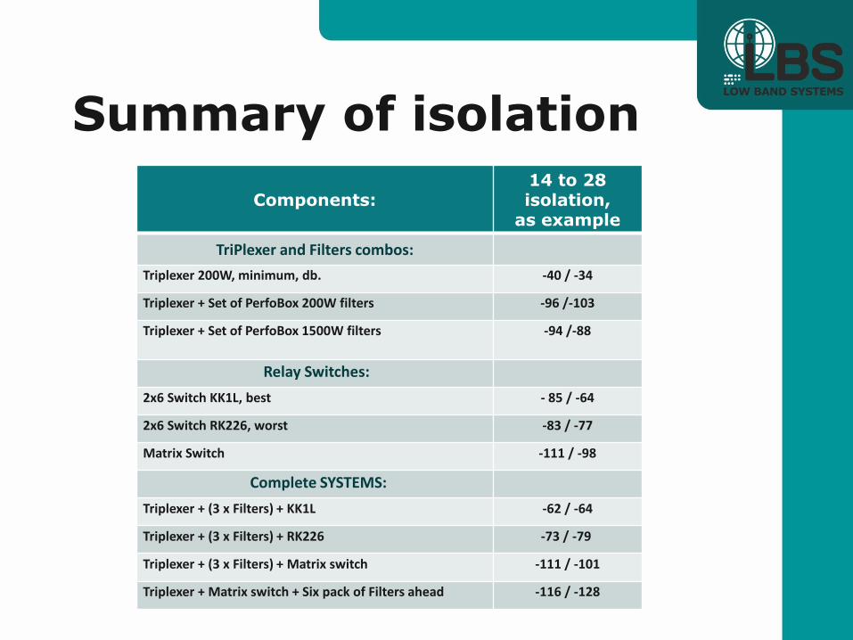
Summary of isolation
Components:
14 to 28 isolation,
as example
TriPlexer and Filters combos:
Triplexer 200W, minimum, db. -40 / -34
Triplexer + Set of PerfoBox 200W filters -96 /-103
Triplexer + Set of PerfoBox 1500W filters -94 /-88
Relay Switches:
2x6 Switch KK1L, best - 85 / -64
2x6 Switch RK226, worst -83 / -77
Matrix Switch -111 / -98
Complete SYSTEMS:
Triplexer + (3 x Filters) + KK1L -62 / -64
Triplexer + (3 x Filters) + RK226 -73 / -79
Triplexer + (3 x Filters) + Matrix switch -111 / -101
Triplexer + Matrix switch + Six pack of Filters ahead -116 / -128

Part II
MULTI BAND antennas
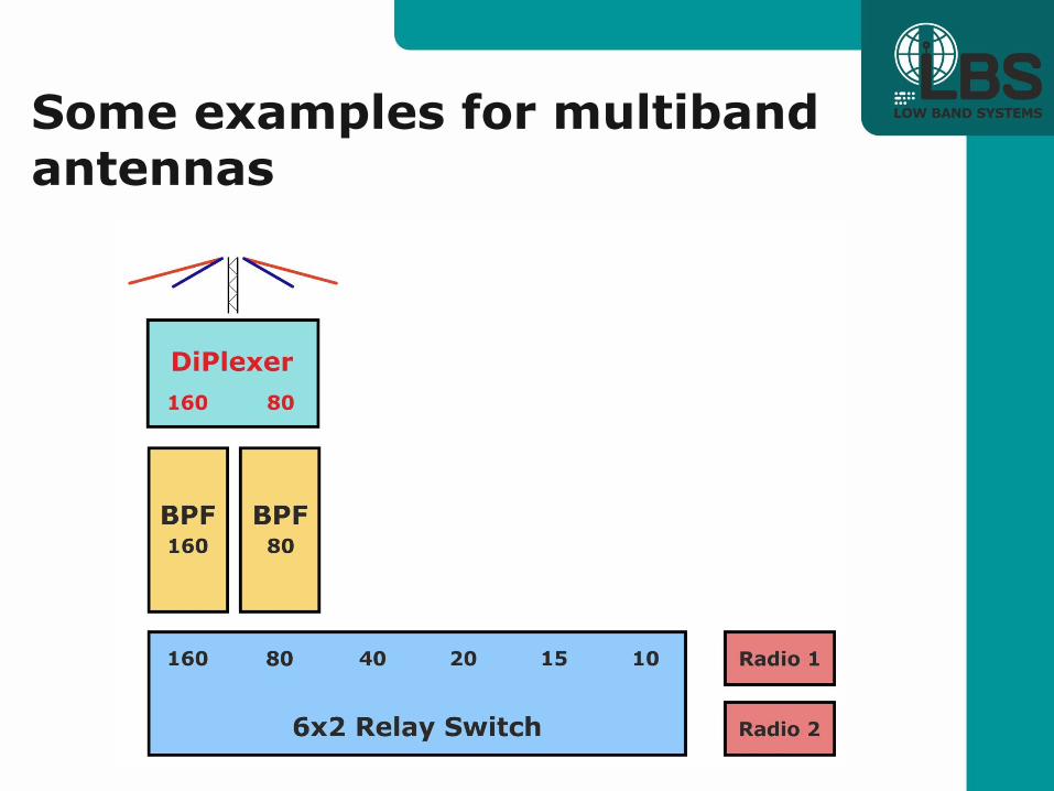
Some examples for multiband antennas
Some examples for multiband antennas
Some examples for multiband antennas

Some examples for multiband antennas

Some examples for multiband antennas
When on 10, you can be on 6 m. also!

Part III.
Upside Down ?

YES!

Benefits:
▪ For in-band remote sites
▪ Hardline and installation time saving solutions

Upside down “bricks”

Upside down “bricks”

Upside down “bricks”

Upside down summary:

Part IV
▪ RECEIVE ONLY APPLICTIONS

Can we have any benefits with Multiplexer technology for receive only applications?
Yes!

Lets compare with the classic of the distribution:
Wide band splitters:
SPLITTER/COMBINER, know also as a “Magic T” or “-3db.”

Wideband splitters:
The weak point is internal losses:
▪ -3,1db. in a 2 way splitters;
▪ -6,3db. in a 4 way splitters;
▪ -9,5db. in a 6-8 way splitters;
Plus losses in a feedline.
For 1000 feet of RG6 size cable it is -3÷4db.
Total losses may be over -12db. in a 6 way splitting!
And 6 way splitting is a must for Winning size Multi stations!
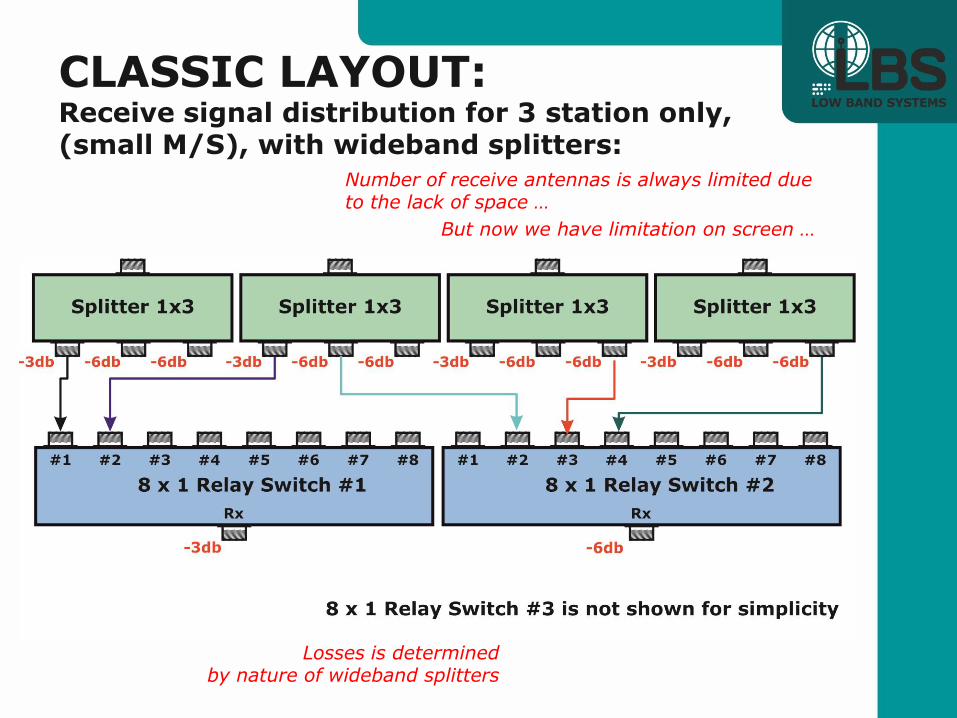
CLASSIC LAYOUT: Receive signal distribution for 3 station only, (small M/S), with wideband splitters:
Losses is determined by nature of wideband splitters
Number of receive antennas is always limited due to the lack of space …
But now we have limitation on screen …
Direction #1 Direction #2 Direction #3 Direction #4

Can we overcome this loss-related problem in a larger size
stations
with the MultiPlexer technology?

Total losses is: -4,1db. station #1 of each band -7,3db. stations #2,3 of each band
Advanced receive signal distribution for M/M, big M/S:
Unlimited number of directions,
Up to 4 bands, 3 station on each band!

Direction #1 Direction #2 Direction #3
Advanced receive signal distribution for M/M, big M/S:
Unlimited number of directions,
Up to 4 bands, 3 station on each band!
For DX pedition:
Coax and installation time saving solutions!

DX pedition advanced layout:
You can first combine (into single feedline),
and then split (at the radios )
different band signals!

DX pedition advanced layout: Direction #1 Direction #2 Direction #3 Direction #4
SINGLE coax feedline to the tent with 4 stations, running on 4 different bands! ANY direction on ANY band!
Losses: -3 db. only! SINGLE Ethernet cable, to control 4 direction on 3 antenna switches with LBS receive antenna systems components!

Q & A?
▪ LowBandSystems, of Russia
▪ DX Engineering - USA distribution