Embed Size (px)
Citation preview

Using Isight Simulation Automation
Tools to Reduce the Cycle Time for
Ship Structural Analysis Process
Simulia Community Conference
Sean Murphy, P. E.
Allyn Boday
Ingalls Shipbuilding

Agenda
• Introduction
• NSRP Modeling and Simulation Project
• Benefits of Isight
• Example of Isight at Work
– Foundation Analysis Part 1 – Model Conversion
– Foundation Analysis Part 2 –Analysis Automation
– Foundation Analysis Part 3 – Optimization
• Conclusion/Questions
2

Introduction
• Since 2007, a team of shipbuilders and software vendors have been
conducting two National Shipbuilding Research Program (NSRP)
projects entitled Improved Methods for the Generation of Full-
Ship Simulation/Analysis Models 1 & 2 (M&S)
• The objective of the two projects was to reduce the cycle time
required to develop large scale full ship analysis models for strength,
stress, shock, and acoustic simulations and assessment
• The team consists of:
• General Dynamics/Electric Boat Corporation (EB)
• Huntington Ingalls Industries/Ingalls Shipbuilding (HII)
• TechnoSoft Inc (TSI)
• Dassault Systémes Simulia Corporation
• Product Data Services Corp. (PDSC)
3

Goal: Analysis Process Improvement
F = mas = Mc/I
Utilize Just the Right Amount of
Analysis
Rules-Based DesignPoint-and-Click Methods Design Re-Use
Simulation Models
Improved Processes
Require Balance
?
Simplified Analysis
CAD Platform Part Analysis
Specialized Analysis
DDAM, Static Analysis
IsogeometricAnalysis

Current Modeling and Simulation Processes
Designs Developed in
CAD environment
• 3-D Product models
• Surface Models
• 2-D Drawings
Finite Element Model
• Models built using Shell and
Beam Elements
• Correct Mass Distribution
Required for Dynamic Analysis
Analysis
• Seaway Loads
• Weapons Effects
Analysis Modeling Space
• Generate Analysis Model Geometry from Design Information

Phases of the Analysis Process
6
CAD Model Phase
CAE Model PhaseSimulation
Phase
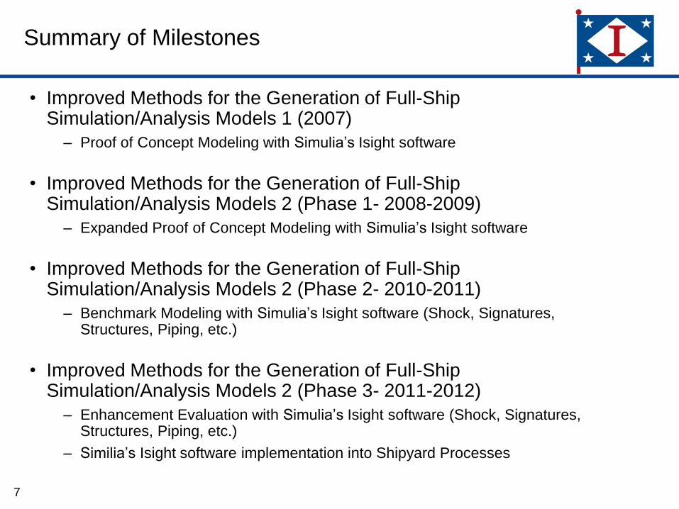
Summary of Milestones
• Improved Methods for the Generation of Full-Ship Simulation/Analysis Models 1 (2007)
– Proof of Concept Modeling with Simulia’s Isight software
• Improved Methods for the Generation of Full-Ship Simulation/Analysis Models 2 (Phase 1- 2008-2009)
– Expanded Proof of Concept Modeling with Simulia’s Isight software
• Improved Methods for the Generation of Full-Ship Simulation/Analysis Models 2 (Phase 2- 2010-2011)
– Benchmark Modeling with Simulia’s Isight software (Shock, Signatures, Structures, Piping, etc.)
• Improved Methods for the Generation of Full-Ship Simulation/Analysis Models 2 (Phase 3- 2011-2012)
– Enhancement Evaluation with Simulia’s Isight software (Shock, Signatures, Structures, Piping, etc.)
– Similia’s Isight software implementation into Shipyard Processes
7

Areas of Evaluation
8
Engineering Department
Program Engineering
Hull Technical
Marine Technical
Electrical Engineering
Field Engineering
Specialty Engineering
Noise, Shock, and
Vibe
Signatures
HSI
Structures
Naval Architecture
Weight Control
Propulsion
Auxiliaries/ Piping
HVAC
Electrical Systems
Combat Systems

Specific Processes that have been evaluated in
Isight
• Completed Evaluations
– Whipping Analysis
– Longitudinal Strength Analysis
– Post Processing/Data Reduction
– Analysis Post/Processing
– Linearized Stress Analysis
– Ship Weight Distribution
– Pipe Shock Test Specimen Design
– Pipe Hanger Support
– Bolt Stress Calculations
– RCS Analysis
– Foundation Analysis
– Optimized Foundation analysis
9

Benefits of Isight
• 4-Fold Cost Avoidance Tool
– Schedule Reduction
• Significant interoperability with other software packages
– Reduction of Manual Errors
• Allows for semi-automation
– Optimization capability
• Allows for more in-depth comparison of design variations
– Archived Documentation
• Improved Communication
• Increase in configuration management
• Training tool
10

Interoperability with other Software Packages
11

10 June 2009
12
Reduction of Manual Errors
Automated Development of Input Files
Run Analysis
Whipping Analysis and Longitudinal Strength Simflow
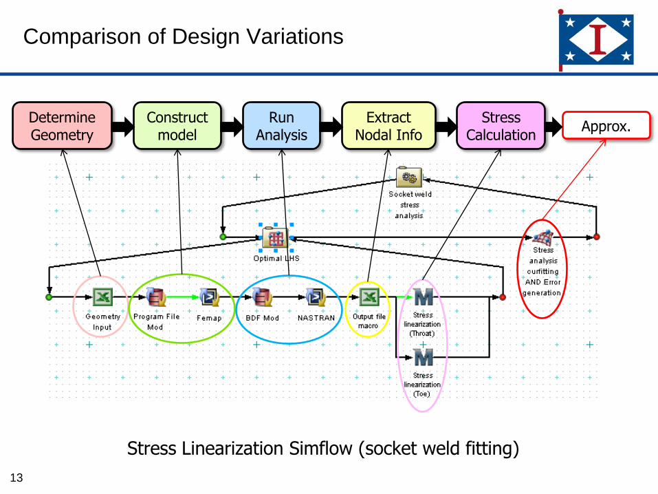
Comparison of Design Variations
13
Construct model
Determine Geometry
Run Analysis
Extract Nodal Info
Stress Calculation
Approx.
Stress Linearization Simflow (socket weld fitting)

Comparison of Design Variations
• Allows for more in-depth comparison of design variations
– Allows for Sensitivity studies
– Better correlation of data points
– Allows for multivariable studies
14
Comparison of P-13 Analysis for the TRT with Pipe Size, Bleg
weld size and insertion as variables
Isight Analysis Results
DM-RM-MT10 Analysis Results

Archived Documentation
15
Construct Model and Analysis
Build Geometry Program
File
Create RCS
Analysis File
Modify RCS Analysis
File
Run RCS Analysis
Change Variable
to a Different
Value
Radar Cross Section Simflow

Training and Configuration Management
16
• Training
– Step by Step process visibally laid out
– Relevant variables highlighted
• Configuration Management–
– All Variables that change are defined.
– Inputs and results can be easily archived
SCL’s
ZX
VariablesHighlighted and defined

INGALLS SHIPBUILDING PRIVATE / PROPRIETARY LEVEL I
17
Foundation Analysis using the
Isight Software
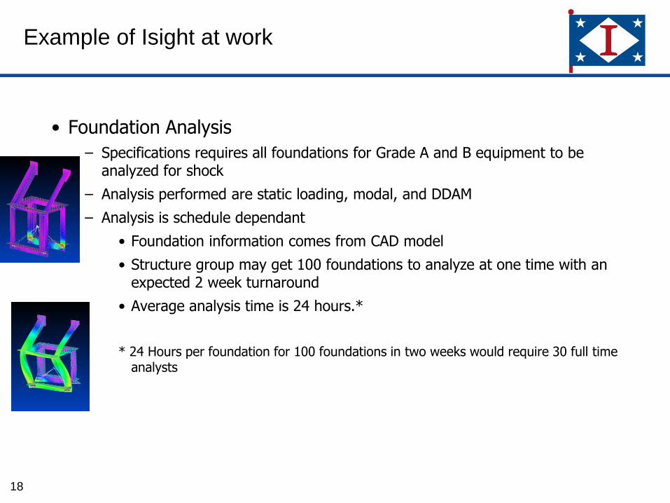
Example of Isight at work
• Foundation Analysis
– Specifications requires all foundations for Grade A and B equipment to be analyzed for shock
– Analysis performed are static loading, modal, and DDAM
– Analysis is schedule dependant
• Foundation information comes from CAD model
• Structure group may get 100 foundations to analyze at one time with an expected 2 week turnaround
• Average analysis time is 24 hours.*
* 24 Hours per foundation for 100 foundations in two weeks would require 30 full time analysts
18

Using Isight to meet schedule demands
• Foundation Analysis broken into 3 parts
– Part 1 – Model Conversion
• Proof of Concept developed by Simulia using CATIA
– Part 2 - Analysis Automation
• Isight Simflow developed by Ingalls Shipbuilding
– Part 3 - Optimization
• Semi-Automated Isight Simflow being developed by Ingalls Shipbuilding
19

Foundation Part 1 – Model Conversion
- NSRP M&S 2 Phase 2
- Simulia developed proof of concept
using CATIA V5
- NSRP M&S 2 Phase 3
- Simulia to improve on using proof
of concept software
- Possible development with Ship
Constructor (Dependent on Ship
Constructor effort)
- Software Evaluation (Task 3) may
provide capability
- Objective:
- Neutral input file (STEP, etc)
- Neutral export file (BDF file, INP
File, etc).
20

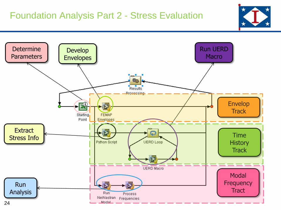
Foundation Analysis Part 2 – Analysis
Automation
21
Fatal Errors?
No
Yes
STOP
Static Input Mod.
%Modal Mass Req’d?
Report:List of all global
and local Failures
Bolt Calc Simflow*
Modal Analysis
While Loop
>80%
<80%
Modal Analysis (first 10 modes)
Mode Shape Images
Static Analysis run (NASTRAN)
Meshed FEA
Model
DDAM Input
Mod. & Run
Model Evaluation
Not Complete Not Complete Completed

Foundation Analysis Part 2 - Simflow
22
Static Run and Error
Check
STOP
Static Input Mod. and
%Modal Mass ?
Fatal Errors?
Modal Analysis While Loop
Modal Analysis (10 modes)
Mode Shape Pictures/DDAM
run/ Model Evaluation
Current setup simply checks the maximum Von Mises stresses against the general global
membrane allowable

Foundation Analysis Part 2 - Stress Criteria
23
• Calculated stresses should be based on Von Mises Failure
Theory
• Design stresses categorized as “general” or “local” and as
“membrane” or “membrane + bending”
• Will require some user input/engineering judgment
• Local stress – occurs in regions of load application or structural
discontinuity
– Considered local if localized stress exceeds the general allowable for
less than 10% of the “effective area” of the load carrying member
– Nodal stresses at points of stress concentrations are unlimited (e.g.
corners, cutouts, point loads, etc…)
– If the above criteria are not met, the stress is categorized as general
Foundation Analysis Part 2 - Stress Evaluation
24
Develop Envelopes
Determine Parameters
Run Analysis
Extract Stress Info
Run UERD Macro
Modal Frequency
Tract
Time History Track
Envelop Track

Foundation Analysis Part 3 - Optimization
• Optimization based on results from Foundation Simflow
• Optimization - Semi- Automated
– Based on the DDAM stress criteria
– Still requires some evaluation from analyst
• Optimization Options
– Reduced Weight
– Reduced Piece Parts and Welding
– Full Optimization (Does not account for standard structural member sizes or
increases in welds)
25

Foundation Analysis Part 3 – Foundation
Simflow Optimization
• Objective is to add optimization capabilities to foundation simflowin some capacity to maintain structural adequacy and minimize weight (may work better for some foundations than others)
• Can modify plate thicknesses, beam element properties, etc…
• Basic foundation optimization yielded a ~35% decrease in weight while still meeting the applicable general stress criteria.
26

Isight Simflow Evaluation
27

Isight and meeting demand schedule
• Isight can help engineering meet design and manufacturing schedule
need dates with little change to existing process
28

Summary
• Ingalls Shipbuilding examined approaches for reducing cycle time required to develop large scale, full-ship analysis models for strength, stress, shock, and acoustic simulations and assessment
• Isight was used on 10 simflows from throughout the Ingalls Shipbuilding Engineering Department
– Experienced a 4-fold cost avoidance
– Also helped meet schedule demands of many analyses required in a short time
• Isight software allows for semi-automation of the Foundation Analysis
– Can reduce analysis time by up to 33%
• Optimization of the Foundation Analysis can be performed with little additional time
– Requires the use of Isight’s Optimization Capability
– Requires some preplanning with the finite element model
– Engineering judgment still required to be make optimization realistic.
29

Questions??
30

31