Embed Size (px)
Citation preview
Revision 5 June 20, 2017
Individual chapters of the Kalsi Seals Handbook are periodically updated. To determine if
a newer revision of this chapter exists, please visit www.kalsi.com/seal-handbook.htm.
NOTICE: The information in this chapter is provided under the terms and conditions of the Offer of
Sale, Disclaimer, and other notices provided in the front matter of this handbook.
Document 3091 © 2017 Kalsi Engineering, Inc. All rights reserved.
Kalsi Seals Handbook
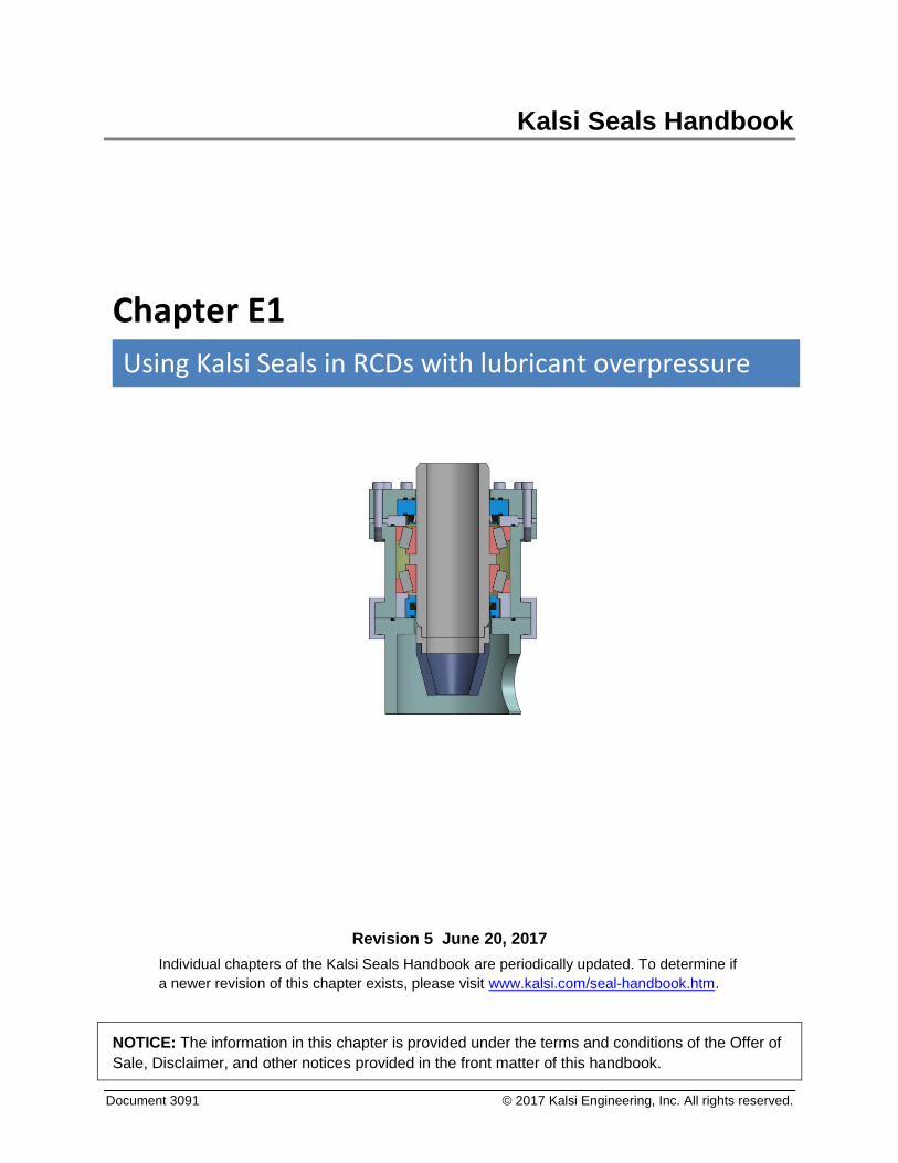
Chapter E1
Using Kalsi Seals in RCDs with lubricant overpressure
Using Kalsi Seals in RCDs with lubricant overpressure Chapter E1 Page 1
Search this handbook Contact Kalsi Engineering
1. Introduction
A rotating control device1 (RCD) reduces formation damage in oilwell drilling (compared
to overbalanced drilling) by maintaining the pressure of the annular fluid column of
drilling mud at a pressure below, or comparable to, that of the reservoir. The reduction in
formation damage helps to optimize the production potential of the well. Drilling with an
underbalanced pressure condition allows the evaluation of well effluents while drilling. It
also reduces differential sticking, and allows less expensive drilling fluids to be used.
Early versions of Kalsi-brand rotary seals began to be used in RCDs in 1991. Since then,
several advances in technology enable our seals to operate in more adverse RCD sealing
conditions, including higher pressure, higher speed, less cooling, lower viscosity
lubricants, and less complicated lubricant supplies. Our high performance seals withstand
relatively high pressure because they incorporate hydrodynamic pumping features that
force a thin film of lubricant into the sealing interface during rotation. The resulting
hydroplaning action reduces friction, wear, and seal-generated heat. We have developed
innovative ways to implement high pressure seals into large diameter high pressure
equipment to further improve performance.
This chapter provides guidance for implementing Kalsi Seals into the type of RCD that
maintains the seal lubricant at a pressure that is slightly greater than the wellbore
pressure. The information in this chapter is also relevant to the design of other types of
high pressure rotating equipment, such as water drilling heads.
2. Pressurized lubricant versus gravity fed lubricant
Seals that are compatible with a non-pressurized seal lubricant are described in Chapters
C17 and C19 of this handbook. See those chapters for seal descriptions, performance
characteristics, and implementation recommendations
Advantages and disadvantages
RCDs that utilize a pressurized seal lubricant can operate at higher well pressures than
RCDs that use a gravity fed lubricant, but involve additional complexity.
1 Also known as a rotating head, rotary blowout preventer, rotating blowout preventer, rotating drilling
head, rotating BOP, rotary BOP, rotary control device, and rotating diverter. If needed, we can provide batch acceptance information to help our customers meet the requirements of API Specification 16RCD, “Specification for Drill Through Equipment—Rotating Control Devices”.
Using Kalsi Seals in RCDs with lubricant overpressure Chapter E1 Page 2
Search this handbook Contact Kalsi Engineering
3. Pressurized lubricant systems
Introduction
The conventional approach to implementing Kalsi Seals in a rotating control device is to
provide a lubricant supply that maintains the lubricant pressure at a value that is greater
than the fluctuating drilling fluid pressure. The purpose of the lubricant overpressure
system is to properly orient the mud-to-oil partitioning seal against the mud-side gland
wall for good abrasive exclusion. In active RCD designs, the lubricant pressure may also
be used to activate the packing element.2
Chapter D11 describes various types of pressurized lubricant supplies.
Computer-controlled lubricant overpressure
Oilfield industry literature indicates that systems with computer-controlled pressure are
successful in RCDs. Such systems maintain the lubricant pressure approximately 300 psi
above the drilling fluid pressure.3 Computer controlled systems also have the advantage
of a large lubricant reservoir, which is good from a lubricant cooling standpoint, and for
accommodating the increased hydrodynamic pumping related leakage of Enhanced
Lubrication Seals (Chapter C5) and Plastic Lined Seals (Chapter C16). Wintertime
operating conditions may require lower viscosity lubricants or lubricant heaters, to
facilitate the lubricant circulation that is employed in computer controlled systems.
Piston amplifier-controlled lubricant overpressure
When sufficient room is available, the differential area piston amplifier type of lubricant
reservoir shown in Chapter D11 may be appropriate for use with an RCD. Consider
incorporating an automatic refill system, which can be controlled by the position of the
piston rod.
Lubricant overpressure generated by controlled flow
As described by Kalsi Engineering’s U.S. Patent 7,798,496,4 a lip seal can be used as the
mud to oil partitioning seal and a Kalsi Seal can be used as the pressure retaining seal, if
a lubricant having a controlled flow rate and a pressure greater than the mud pressure is
introduced between the lip seal and the Kalsi Seal. One way to control the lubricant flow
2 For examples of active RCD arrangements, see US Patents 3,621,912, 5,178,215, 5,224,557, 5,588,491,
and 5,662,171, and 9,316,319. Active RCDs may convey more breakout torque to the mandrel, compared to passive RCDs. Active RCDs typically pressurize at least part of the bearing housing, which increases bearing clearance, and therefore increases shaft runout and deflection — increasing the need for seal carriers or backup rings that follow lateral shaft motion. Active RCDs typically require a lubricant pressure control system.
3 For an example of a computer-controlled pressure system used to maintain 300 psi lubricant overpressure in an RCD, see U.S. Patent 6,554,016, titled "Rotating blowout preventer with independent cooling circuits and thrust bearing".
4 Contact Kalsi Engineering, Inc. for licensing details.
Using Kalsi Seals in RCDs with lubricant overpressure Chapter E1 Page 3
Search this handbook Contact Kalsi Engineering
rate is to use a positive displacement pump to supply the seal lubricant. The flow vents
through the dynamic interface of the lip seal, and into the drilling mud, lubricating the lip.
The slow constant flow provided by the pump causes the lubricant pressure to equal the
mud pressure plus whatever slight differential pressure is required to vent the seal.
One advantage of such systems is hardware simplicity. Another is the low breakout
torque of the lip seal, making the stripper rubber less likely to slip on the drill string. Yet
another advantage is the contaminant flushing action of the lubricant flow that passes
through the dynamic interface of the lip-type partitioning seal. When designing such a
system, verify the venting pressure of the lip seal by testing.
4. Rotary seal locations in an RCD with lubricant overpressure
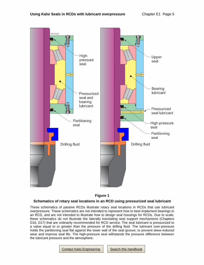
Figure 1 is a schematic that illustrates two different ways to arrange rotary seals in a
passive oilfield RCD. The heart of the assembly is a rotating elastomeric packing
element that seals around the rotating drillstring. The packer element is mounted on a
bearing guided rotating shaft that is located partially within a stationary bearing housing.
Rotary seals partition the drilling fluid from the lubricant, retain the lubricant, and
withstand the pressure difference between the drilling fluid and the atmosphere.
Due to scale, the seal carriers in Figure 1 are highly schematic, and do not represent the
axially force-balanced, laterally translatable seal mounting arrangements that are
typically recommended for RCDs that have pressurized lubricant systems. If laterally
translatable seal mounting arrangements are not used, the upper and lower radial bearings
should be mounted within the housings that locate the rotary seals, to minimize shaft
runout and deflection at the rotary seals.
In both images of Figure 1:
• The partitioning seal partitions pressurized drilling fluid from the pressurized seal
lubricant, and the high-pressure seal retains the pressure of the seal lubricant.
• The pressure of the seal lubricant is pressurized to a value that is greater than the
pressure of the drilling fluid in the wellbore.
• The bearing lubricant is preferably circulated for cooling purposes, extracting heat
generated by the seals and bearings.
Using Kalsi Seals in RCDs with lubricant overpressure Chapter E1 Page 4
Search this handbook Contact Kalsi Engineering
The left-hand image of Figure 1
In the left-hand image of Figure 1, oppositely facing Kalsi Seals are mounted above and
below the bearings, and a pressurized lubricant is introduced between the seals. This
arrangement has the disadvantage of pressurizing and expanding the bearing housing,
which decreases bearing guidance of the rotating shaft.
The left-hand arrangement also has the potential disadvantage of exposing the high
pressure shaft seal to environmental contaminants — for example, a drilling fluid spill.
Because of this contamination risk, floating backup rings and plastic lined seals should be
avoided at the high-pressure seal location of the left-hand image, unless they are well-
protected by an outboard trash seal (not shown). An all elastomer high pressure seal and a
laterally translating seal carrier (Chapter D16) would not require the protection of an
outboard trash seal.
An advantage of the left-hand arrangement is that the heat zone created by the high
pressure seal is well-separated from the heat zone created by the partitioning seal.
The right-hand image of Figure 1
In the right-hand image of Figure 1, oppositely facing Kalsi Seals are mounted below the
bearings, and a pressurized seal lubricant is introduced between the seals. This
arrangement has the advantage of preventing pressure-related expansion of the bearing
housing, which helps to maintain good bearing guidance of the rotating shaft. It also has
the advantage of protecting the pressure retaining seal from environmental contaminants.
The low pressure bearing lubricant can easily be circulated for cooling purposes.
In the right-hand image of Figure 1, a third rotary seal, at the top of the unit, retains the
bearing lubricant and protects the bearings from environmental contaminants. If the
bearing lubricant is circulated, this upper seal must withstand the pressure generated by
the viscous resistance of the lubricant. In surface units, this third rotary seal can be
somewhat protected from environmental abrasives by using the weir and rotating cover
that are described in U.S. Patent 8,505,924.5
If desired, pressure can be staged across the middle and upper rotary seals by introducing
the bearing lubricant at a pressure that is about half that of the seal lubricant. Pressure
staging requires that the upper seal be a type capable of withstanding significant
differential pressure. For examples of how pressure staging can be accomplished in
RCDs, see our US Patents 6,227,547 and 9,429,238.6
5 Contact Kalsi Engineering, Inc. for licensing details
6 Contact Kalsi Engineering, Inc. for licensing details.
Using Kalsi Seals in RCDs with lubricant overpressure Chapter E1 Page 5
Search this handbook Contact Kalsi Engineering
Figure 1
Schematics of rotary seal locations in an RCD using pressurized seal lubricant
These schematics of passive RCDs illustrate rotary seal locations in RCDs that use lubricant overpressure. These schematics are not intended to represent how to best implement bearings in an RCD, and are not intended to illustrate how to design seal housings for RCDs. Due to scale, these schematics do not illustrate the laterally translating seal support mechanisms (Chapters D16, D17) that are ordinarily recommended for RCD service. The seal lubricant is pressurized to a value equal to or greater than the pressure of the drilling fluid. The lubricant over-pressure holds the partitioning seal flat against the lower wall of the seal groove, to prevent skew-induced wear and improve seal life. The high-pressure seal withstands the pressure difference between the lubricant pressure and the atmosphere.
Using Kalsi Seals in RCDs with lubricant overpressure Chapter E1 Page 6
Search this handbook Contact Kalsi Engineering
5. Adverse conditions encountered in RCD sealing
The rotating control device (RCD) presents many difficult rotary sealing challenges,
including:
• Large sealing diameter
• Large manufacturing tolerances
• Large assembly clearances
• Limited axial space for the rotary seals
• Misalignment and runout due to severe mechanical loads
• Pressure induced breathing of large housing components
• Significant seal and bearing generated heat
• Large differential thermal expansion
• High differential pressure
• High surface speed
6. Maintaining a suitable high-pressure extrusion gap in RCDs with pressurized lubricant
Background information
Properly implementing Kalsi Seals in high differential pressure applications requires
meeting two basic extrusion gap requirements (Chapter D7):
1. The radial extrusion gap clearance must be small to control seal extrusion, and
2. Heavily loaded metal-to-metal contact at the extrusion gap must be avoided.
These two requirements are difficult to meet simultaneously with rotary shafts that have
high side load and deflection. When lateral shaft motion exceeds radial extrusion gap
clearance, the extrusion gap bore becomes a de-facto radial bearing and generates seal-
damaging heat. As a consequence, the seal experiences a lowered modulus of elasticity,
which reduces extrusion resistance. The heat buildup also accelerates seal compression
set. In severe cases, local seal melting can occur. The heavily loaded metal-to-metal
contact can wear the RCD shaft and housing, increasing the extrusion gap, roughening
the shaft, and damaging (burring) the critical extrusion gap corner on the low-pressure
side of the seal. If relative axial motion occurs due to assembly clearances and
Using Kalsi Seals in RCDs with lubricant overpressure Chapter E1 Page 7
Search this handbook Contact Kalsi Engineering
component elasticity, then damage can result to the RCD seal, from riding over the
roughened shaft surface. Roughening at the extrusion gap corner between the seal groove
and the extrusion gap can also significantly accelerate seal extrusion damage.
If the radial extrusion gap clearance is too large, then the differential pressure causes the
seal to protrude into the extrusion gap. Runout and pressure breathing can flex and
destroy the protruding material, leaving a jagged seal edge that interferes with optimal
seal lubrication. The differential pressure causes more protrusion, and the damage cycle
eventually destroys the seal.
Description of the problem
Several factors prevent a small shaft-to-housing extrusion gap in conventionally designed
large diameter equipment such as RCDs. Manufacturing tolerances are necessarily large,7
which directly affects the size of the extrusion gap. Large manufacturing tolerances also
increase bearing internal and mounting clearances, thus permitting increased shaft runout
and misalignment. Large components are often subject to significant elastic deformation
when exposed to high pressure or large mechanical loads. Significant dimensional
variability from differential thermal expansion caused by seal and bearing heat is also a
concern.
Such dimensional variability can have a dramatic effect on assembly clearances and
bearing internal clearances, which can permit large dynamic runout and articulation of
the shaft, and can cause large variations in the radial extrusion gap clearance.
Consequently, in large diameter equipment such as rotary control devices, if the extrusion
gap is sized for optimal high-pressure extrusion resistance, then it is impossible to guide
the shaft so precisely that it will not rub on the housing at the extrusion gap, without the
use of a laterally translatable seal assembly.
The failure sequence of dual stripper arrangements may have a significant effect on shaft
diameter, and consequently, on shaft-to-housing extrusion gap clearance. Clearance
analysis must be performed with the lower stripper element effective, and with the lower
stripper element failed, and must consider any anticipated thermal expansion of the shaft.
Description of a hardware solution
The solution for misalignment and pressure breathing issues, like those described above,
lies in using laterally translating seal assemblies. Chapters D16 and D17 address these
design issues, and describes solutions that significantly extend rotary seal performance
7 Figure 3.11 of the book "Technical Drawing", Seventh Edition (Macmillan Publishing Co.), provides total
tolerance recommendations for diameters up to 21 inches (533.4 mm) for various machining methods. Divide total tolerance by two for bilateral tolerance.
Using Kalsi Seals in RCDs with lubricant overpressure Chapter E1 Page 8
Search this handbook Contact Kalsi Engineering
and life, compared to conventional non-translating designs. These laterally translating
arrangements provide the small radial extrusion gap clearance necessary for optimum
rotary seal operation in pressurized lubricant systems, while preventing the high frictional
heat generation that can occur between the rotary shaft and a conventional seal carrier.
We recommend laterally translating seal assemblies for Kalsi Seals that are used as
pressure retaining seals in rotating control devices. The high pressure seal can be
mounted in either laterally translating seal carrier arrangement (Chapter D16) or a
laterally translating backup ring arrangement (Chapter D17). The Type 2 laterally
translating backup ring arrangement permits a smaller and more stable extrusion gap
clearance, and for this reason is superior to the laterally translating backup ring
arrangement for high pressure sealing. When the laterally translating backup ring
arrangement is used at the upper seal location of an RCD, however, an outboard seal of
some type is required to protect the journal bearing surface of the backup ring from
contaminants. It is preferred to locate the floating backup ring below the bearings.
If possible, the partitioning seal should also be mounted in a laterally translating seal
carrier arrangement, such as the partially balanced seal carrier that is shown in Chapter
D16. Such seal carriers help to isolate the partitioning seal from dramatic compression
changes caused by shaft deflection and runout, and help to protect the seal from constant
radial sliding against the wall of the groove that mounts the seal. These factors help to
reduce third body abrasion of the partitioning seal.
Possible alternate solutions when laterally translating assemblies cannot be used
Existing equipment may not accommodate the use of laterally translating seal assemblies,
and is likely to have relatively large extrusion gap clearance to accommodate shaft
runout, misalignment, and vibration. Consider using plastic lined Kalsi Seals or Extra
Wide Kalsi Seals with the low friction treatment in such situations, to have the best
chance of bridging larger extrusion gap clearances.
A pair of 10.50” PN 682-20-318 plastic lined RCD seals was tested for 187 hours at
2,300 psi (15.86 MPa and 100 rpm, using a 0.020” radial extrusion gap clearance
between the shaft and the seal carrier. The rotary seal that was closest to a small amount
of coolant circulation was in perfect condition, and the seal that was farthest from the
circulation was slightly worn, and was exhibiting increasing leakage. Plastic lined seals
should not be used where they may be exposed to abrasive media, such as drilling fluid.
Using Kalsi Seals in RCDs with lubricant overpressure Chapter E1 Page 9
Search this handbook Contact Kalsi Engineering
Although we have no comparable test data with 10.50” all-elastomer Extra Wide Kalsi
Seals,8 we experience steady sales of large diameter Extra Wide Kalsi Seals in both
single and dual durometer configurations. See the catalog section of the handbook and
our blog for the latest test information.
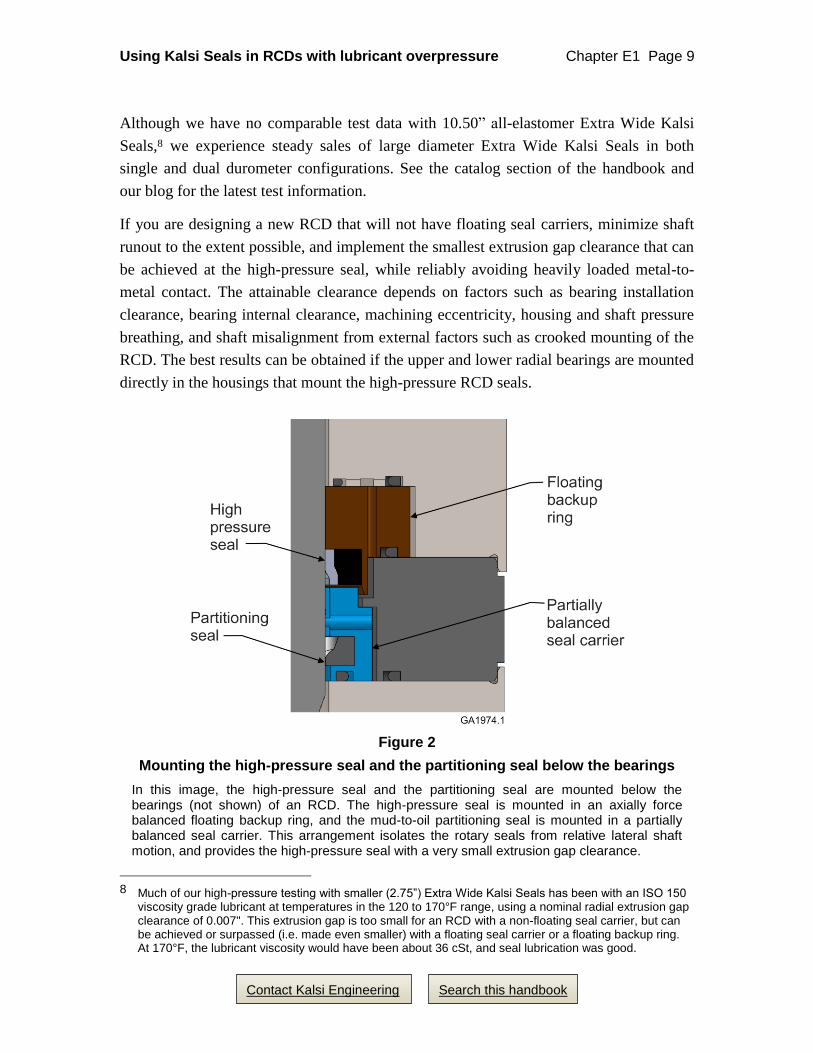
If you are designing a new RCD that will not have floating seal carriers, minimize shaft
runout to the extent possible, and implement the smallest extrusion gap clearance that can
be achieved at the high-pressure seal, while reliably avoiding heavily loaded metal-to-
metal contact. The attainable clearance depends on factors such as bearing installation
clearance, bearing internal clearance, machining eccentricity, housing and shaft pressure
breathing, and shaft misalignment from external factors such as crooked mounting of the
RCD. The best results can be obtained if the upper and lower radial bearings are mounted
directly in the housings that mount the high-pressure RCD seals.
Figure 2
Mounting the high-pressure seal and the partitioning seal below the bearings
In this image, the high-pressure seal and the partitioning seal are mounted below the bearings (not shown) of an RCD. The high-pressure seal is mounted in an axially force balanced floating backup ring, and the mud-to-oil partitioning seal is mounted in a partially balanced seal carrier. This arrangement isolates the rotary seals from relative lateral shaft motion, and provides the high-pressure seal with a very small extrusion gap clearance.
8 Much of our high-pressure testing with smaller (2.75”) Extra Wide Kalsi Seals has been with an ISO 150
viscosity grade lubricant at temperatures in the 120 to 170°F range, using a nominal radial extrusion gap clearance of 0.007". This extrusion gap is too small for an RCD with a non-floating seal carrier, but can be achieved or surpassed (i.e. made even smaller) with a floating seal carrier or a floating backup ring. At 170°F, the lubricant viscosity would have been about 36 cSt, and seal lubrication was good.
Using Kalsi Seals in RCDs with lubricant overpressure Chapter E1 Page 10
Search this handbook Contact Kalsi Engineering
7. Heat dissipation in RCDs
Dissipation of seal and bearing generated heat is a matter of significant concern in many
types of equipment because high temperatures negatively impact seal pressure capacity
and life. In large diameter, high pressure equipment such as rotary control devices, high
surface speed increases the concern. Chapter D8 provides general information about heat
transfer considerations. While third party patents protect certain approaches to heat
dissipation in rotary control devices, expired patents mention other approaches.9
Our thermal analysis of rotary control devices indicates that circulation of a low-pressure
coolant immediately outboard of the high-pressure rotary seal is very effective at
controlling seal temperature. This arrangement requires a low pressure outboard seal, a
small pump, and a heat exchanger. In our analysis, even a coolant flow rate as low as one
gallon per minute was very effective at minimizing seal temperature.
Seal generated heat
Seal generated heat is a function of running torque and rotary speed. Among the various
types of Kalsi Seals used in pressurized lubricant type RCDs, seals with enhanced
lubrication wave patterns have the lowest running torque.
Bench testing isn’t the best indicator of whether circulation is required
We know that in an RCD, circulation for cooling purposes is desirable in terms of
obtaining the best high pressure seal performance. Although we perform full scale seal
testing with and without cooling circulation, we don’t believe our tests are a good
indicator of whether circulation will be required on an actual RCD that has different heat
transfer characteristics than our fixture. We recommend that RCDs be designed to
accommodate circulation when possible. Testing can be performed to determine the
pressure and speed capacity of the RCD with and without cooling.
8. Rotary seal breakout torque
Introduction
Rotary seal breakout torque can be a concern in passive pressure control devices, because
they may depend solely on friction between the packer element and the drillstring to
overcome seal and bearing breakout friction.
9 For examples of patents that mention fluid circulation in rotary control devices, see US Patents
4,143,881, 4,383,577, 5,178,215, 5,224,557, 5,588,491, 6,227,547, and 7,836,946.
Using Kalsi Seals in RCDs with lubricant overpressure Chapter E1 Page 11
Search this handbook Contact Kalsi Engineering
The high-pressure shaft seal
Among the various types of Kalsi Seals that can be used to retain lubricant overpressure
in RCDs, plastic lined Kalsi Seals have the lowest breakout torque. The breakout friction
of Kalsi Seals with elastomeric lips can be reduced significantly with our low friction
(LF) treatment. See Chapter C12 for information on the treatment, and for breakout
torque test data.
In our 7 day, 1,000 psi room temperature breakout torque tests, seals with -106
construction were used as the baseline. Seals with the -106 construction and the low
friction treatment had about 56% of the breakout torque of the baseline seals, and seals
with the -307 plastic lined construction had about 32% of the breakout torque of the
baseline seals. The breakout torque of -303 plastic lined seals was only slightly greater
than -307 seals. A low viscosity lubricant, Aeroshell 560, was used to assemble the tests.
The mud to oil partitioning seal
In conventional lubricant overpressure type RCDs, the mud to oil partitioning seal is a
single durometer, all elastomeric Kalsi Seal, which can be treated for reduced breakout
torque if desired. See chapter C12 for breakout torque test data. Plastic Lined Kalsi Seals
should not be used as partitioning seals.
The partitioning seal with the lowest breakout torque would be a lip seal used with a
controlled flow of lubricant, as described above.
9. Pressure retaining seals for RCDs with lubricant overpressure
Using Enhanced Lubrication Seals as pressure retaining seals
While several types of Kalsi Seals are used as pressure retaining seals in rotating control
devices, not every type of Kalsi Seal is suitable for sealing high differential pressure with
the relatively low-viscosity lubricants that such devices may use. With 0.007” (0.18 mm)
radial extrusion gap clearance, standard width Enhanced Lubrication Kalsi Seals are
suitable for 1,500 to 2,000 psi (10.34 to 113.8 MPa) operation with lubricant viscosities
as low as an ISO 32 viscosity grade, and can handle greater pressures with increased
lubricant viscosity. Enhanced Lubrication Seals run much cooler than Kalsi Seals that
have less aggressive wave forms, and are available in an extra-wide dynamic sealing lip
width that provides more high pressure extrusion resistance at the expense of more
breakout torque.
Enhanced Lubrication Seals have greater hydrodynamic pumping related leakage than
Wide Footprint Seals, particularly in conditions with lower operating pressure or low
operating temperature. It is important to design the lubricant supply system with
Using Kalsi Seals in RCDs with lubricant overpressure Chapter E1 Page 12
Search this handbook Contact Kalsi Engineering
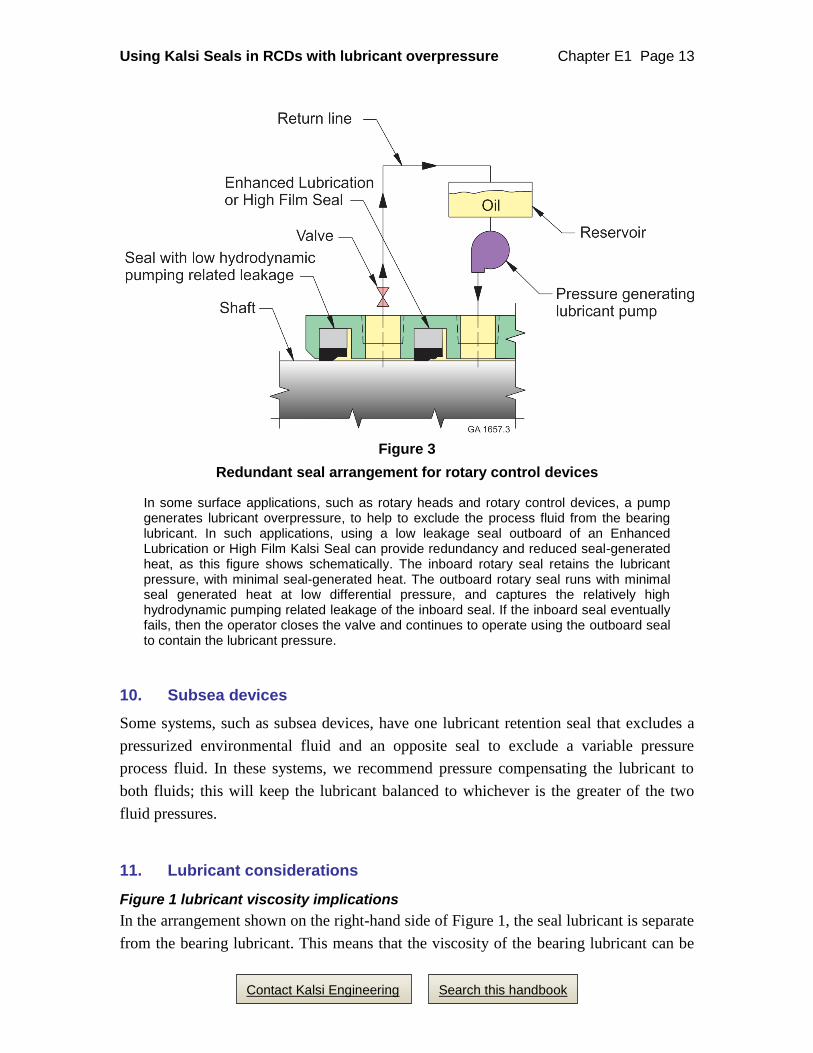
sufficient volume to accommodate this leakage. Figure 3 shows a dual seal arrangement
where the outer seal captures leakage of the inner seal, and then returns it to the lubricant
reservoir.10
Using Plastic Lined Kalsi Seals as pressure retaining seals
We have tested PN 682-5-303 extra wide plastic lined seals in conjunction with a floating
backup ring (Chapter D17) that simulated the 0.008” diametric clearance that a 10”
floating backup ring would require. The lubricant pressure was 3,000 psi, and the shaft
runout was 0.010” FIM. The first test completed its scheduled 200 hour duration, and the
second test completed its scheduled 300 hour duration. The high performance rotary seals
were still effective after the tests. The plastic lining bridges the extrusion gap better in
high differential pressure conditions, compared to rotary seals made entirely from
elastomer. This is because the modulus of the plastic lining is greater than the modulus of
an elastomeric seal.
See Section 6 of this chapter for a description of a 187 hour, 2,300 psi (15.86 MPa) test
of a pair of 10.50” plastic lined seals using a 0.040” diametric extrusion gap clearance.
See the catalog section of the handbook and our blog for the latest test information.
Using zigzag-type Kalsi Seals as pressure retaining seals
We have successfully tested 10.50” (266.7mm) PN 381-35-11 rotary seals with floating
backup rings at a differential pressure of 1,500 psi (10.34 MPa) for 120 hours at 190 rpm
using an ISO 320 viscosity grade synthetic hydrocarbon oil as the seal lubricant.
To simulate the cooling afforded by the limited drilling fluid exposure an RCD mandrel
experiences in the region between the packing element and the mud-to-oil partitioning
seal, a low-pressure coolant was circulated at three to four gallons a minute through a
sealed channel that is axially remote from the test seal. The temperature of the coolant
ranged from 108 to 114°F, and the temperature of the seal lubricant inboard of the test
seal, ranged from 210 to 235°F. Although the Kalsi Seal was separated axially from the
circulating coolant, it was in virtually new condition after the test.
From this test, we believe that the floating backup ring greatly improves the pressure
retaining performance of zigzag-type Kalsi Seals, and allows them to operate cooler than
they otherwise would. This may be a useful approach when attempting to design an RCD
that has no external lubricant supply system.
10 U.S. Patent 8,505,924. Contact Kalsi Engineering for licensing information.
Using Kalsi Seals in RCDs with lubricant overpressure Chapter E1 Page 13
Search this handbook Contact Kalsi Engineering
Figure 3
Redundant seal arrangement for rotary control devices
In some surface applications, such as rotary heads and rotary control devices, a pump generates lubricant overpressure, to help to exclude the process fluid from the bearing lubricant. In such applications, using a low leakage seal outboard of an Enhanced Lubrication or High Film Kalsi Seal can provide redundancy and reduced seal-generated heat, as this figure shows schematically. The inboard rotary seal retains the lubricant pressure, with minimal seal-generated heat. The outboard rotary seal runs with minimal seal generated heat at low differential pressure, and captures the relatively high hydrodynamic pumping related leakage of the inboard seal. If the inboard seal eventually fails, then the operator closes the valve and continues to operate using the outboard seal to contain the lubricant pressure.
10. Subsea devices
Some systems, such as subsea devices, have one lubricant retention seal that excludes a
pressurized environmental fluid and an opposite seal to exclude a variable pressure
process fluid. In these systems, we recommend pressure compensating the lubricant to
both fluids; this will keep the lubricant balanced to whichever is the greater of the two
fluid pressures.
11. Lubricant considerations
Figure 1 lubricant viscosity implications
In the arrangement shown on the right-hand side of Figure 1, the seal lubricant is separate
from the bearing lubricant. This means that the viscosity of the bearing lubricant can be
Using Kalsi Seals in RCDs with lubricant overpressure Chapter E1 Page 14
Search this handbook Contact Kalsi Engineering
selected based on the viscosity requirements of the bearings, and the viscosity of the seal
lubricant can be optimized for the high-pressure and partitioning seals. For example, if
enhanced lubrication seals are being used, the seal lubricant can be a relatively low
viscosity lubricant, to minimize hydrodynamic pumping related seal leakage. It must be
understood, however, that the hydrodynamic pumping related leakage of the high
pressure seal will mix with, and ultimately lower, the viscosity of the bearing lubricant.
In the arrangement shown on the right-hand side of Figure 1, the rotary seals and the
bearings share the same lubricant, and viscosity requirements of both must be met. For
example, and ISO 150 viscosity grade lubricant may be satisfactory for the bearings, but
the viscosity may be too low for some types of Kalsi Seals. For another example, an ISO
680 viscosity grade lubricant may be satisfactory for the bearings, but will cause
substantial hydrodynamic pumping related leakage with enhanced lubrication seals.
Temperature considerations
Lower temperatures increase lubricant viscosity, which increases hydrodynamic pumping
related seal leakage. In RCDs that circulate the lubricant through a pinch valve to control
lubricant overpressure, lower temperatures can increase the lubricant viscosity to the
point where circulation becomes impossible. Regardless of how the lubricant
overpressure is created, wintertime conditions can increase the lubricant viscosity to the
point that the lubricant pressure can no longer track the mud pressure.
Since an RCD may be used in wintertime conditions, these temperature implications
require an engineered solution. Possibilities include:
• Using lower viscosity lubricants in wintertime conditions.
• Using lubricant heaters.
• In seal arrangements like the right-hand side of Figure 1, using an arctic
grade, high viscosity index hydraulic fluid as the seal lubricant.
• Using higher lubricant overpressure until the equipment warms up.
12. Full scale testing of RCD seals
To minimize scaling issues, Kalsi Engineering invested in a test fixture for testing RCD
seals at pressures up to 3,500 psi. The fixture tests a pair of 10.50” seals at once, using a
mandrel that approximates the thermal mass of an actual RCD mandrel. This allows us to
perform more realistic comparisons of the pressure and speed capacity of various rotary
shaft seal designs, compared to small diameter seal tests. Our willingness to invest in
such research sets us apart as a rotary seal manufacturer.
Using Kalsi Seals in RCDs with lubricant overpressure Chapter E1 Page 15
Search this handbook Contact Kalsi Engineering
The pressure is supplied between the seals, so that each seal simulates the high-pressure
rotary seal location of an RCD. By swapping out relatively inexpensive internal
components, the fixture can be used with or without laterally translating seal assemblies,
and with various amounts of extrusion gap clearance.
The fixture can be operated with or without a circulating coolant. The data acquisition
system measures relevant parameters, and provides automatic shutdown if data exceeds
predetermined limits. This allows the fixture to safely operate continuously, 24 hours a
day, without human intervention.
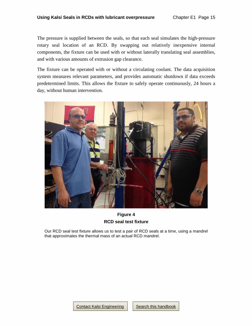
Figure 4
RCD seal test fixture
Our RCD seal test fixture allows us to test a pair of RCD seals at a time, using a mandrel that approximates the thermal mass of an actual RCD mandrel.