Embed Size (px)
Citation preview
TRANSONIC CASCADE FLOW CALCULATIONS USING p-. 2"
NON-PERIODIC 6-TYPE GRIDS
Andrea Arnone* Institute for Computational Mechanics in Propulsion
Lewis Research Center Cleveland, Ohio 44135
and Meng-Sing Liou and Louis A. Povinelli
National Aeronautics and Space Administration 1 kki: 1
Lewis Research Center Cleveland, Ohio 44135
ABSTRACT
A new kind of C-type grid is proposed for turbomachinery flow calculations. This grid is non- periodic on the wake and results in minimum skewness for cascades with high turning and large camber. Euler and Reynolds averaged Navier-Stokes equations are discretized on this type of grid using a finite volume approach. The Baldwin-Lomax eddy-viscosity model is used for turbulence closure. Jameson's explicit Runge-Kutta scheme is adopted for the integration in time, and computational efficiency is achieved through accelerating strategies such as multigriding and residual smoothing. A detailed numerical study has been carried out for a turbine rotor and for a vane. A grid dependence analysis is presented and the effect of artificial dissipation is also investigated. Comparison of calculations with experiments clearly demonstrates the advantage of the proposed grid.
INTRODUCTION
The history of turbomachinery design has seen important evolution in recent years. While the need for efficiency and weight reduction has driven a designer to investigate the details of the complex flowfields in which each component is expected to operate, Computational Fluid Dynamics (CFD), however, has progressed rapidly and increased its reliability as an effective designing tool. Thus, it is reasonable to see CFD taking an indispensable role in the future design and optimization of turbomachinery. In the past few years several two and three-dimensional codes for solving inviscid flows have reached a high level of maturity and are commonly used in turbomachinery applications(see e.g. references 1 and 2). However, the inviscid predictions do not provide any information about heat transfer and boundary-layer thickening, which are important quantities in the analysis of internal flows, specifically in turbomachines, and generally require solutions of Navier-Stokes equations. Although important progress has been made in
*Currently at University of Florence, Florence, Italy. Work funded by Space Act Agreement C99066G.
solving the Navier-Stokes equations (e.g. references 3-6), more work still needs to be done in terms of robilstness and accuracy, and especially in terms of turbulence modelling. In addition, in the case of cascade flow solutions, the grid generation process seems to be an item that still needs to be improved.
Rotor and stator cascades of modern turbomachinery are often characterized by a high turning geometry and/or by strong flow deviations from the axial so that the generation of meshes capable of picking up the flow details is not straightfoward. Procedures that use periodicity generally give rise to highly distorted meshes. In the present work, this problem is solved by the introduction of non-periodic elliptic C-type grids. The removal of periodicity allows the grid to be only slightly distorted even for cascades having a large camber and a high stagger angle. On these new kinds of grids the Euler and Navier-Stokes equations are efficiently solved using a Runge-Kutta scheme in conjunction with accelerating techniques like multigridding and variable coefficient implicit residual smoothing. The two-layer eddy-viscosity model of Baldwin and Lomax is used for the turbulence closure.
Due to the complexity of transonic cascade flows, it was believed worthwhile to investigate the convergence in space of the computed solutions. A grid independence study is carried out in both grid directions, and also the effect of the fourth order dissipation on the boundary layer is discussed by comparing the wall skin friction coefficient.
The capability of the procedure is shown by comparing computed results to experiments for a typical highly loaded gas turbine rotor and for a high turning nozzle. With the accelerating strategies, a solution for viscous flow can be obtained in a few minutes on a modern supercomputer.
COMPUTATIONAL GRID
It is known that the grid structure must be selected carefully in order to achieve an accurate resolution of a complex flow field. When dealing with the construction of grids for turbomachinery blade passages the following aspects are of importance: (a) accurate leading and trailing edge flow description, (b) description of the wake, and (c) imposition of periodicity.
Sheared H-type grids are fairly common in turbomachinery applications. They are easy to generate and to extend to three-dimensional applications. Unfortunately those grids provide poor leading and trailing edge fiow reproduction. On the leading edge truncation errors due to the grid distortion introduce extra entropy which is transported downstream on the blade surface.
Those kind of problems do not exist on 0-type grids. However, in this case the difficulty lies in the wake where clustering grid and avoiding distortion is desired. In addition, when the flow is transonic, 0-type meshes are not suitable for a fine reproduction of the outlet shock system.
Therefore, with respect to the first two points, we can conclude that, if a single grid structure is chosen, the C-type seems to have the best overall capability.
For item (c) it is evident that a simple point-to-point correlation is the easiest way of imposing periodicity between the various blades. Unfortunately it is common in turbine blading to have high turning geometry with an outlet flow that is strongly deviated from the axial. In such a case, the imposition of the circumferential grid correspondence results in highly distorted grids and
this distortion is reflected in a low resolution of the flow gradients. Our experience in computing transonic cascade flows has suggested that when the outlet flow angle (from the axial) exceeds 70 degrees, it is difficult to reproduce the shock system correctly, and the sheared N-type grids often work better than the 6-type.
We therefore believed it was necessary to break the point-to-point grid correspondence to allow a better grid orientation. The grid periodicity can be removed on the external part of the mesh or on the wake. In practice, only one of the two options is sufficient. We selected the second one for two reasons. Firstly, the wake can be roughly followed as a straight line and interpolations between the coarse and fine part of the domain are straightfoward. Secondly, this solution allows the trailing-edge shock to intersect the coarse part of the mesh as far as possible. This point will become evident later as we discuss the calculated results.
The non-periodic C-type grids used for the present calculations are generated with an elliptic procedure that solves the discretized Poisson equations using a relaxation procedure by Soren- son(ref. 7). Forcing functions as proposed by Steger and Sorenson(ref. 8) are used to control the grid spacing and orientation at the wall, while on the external part of the mesh periodicity conditions are imposed. Grids for viscous flow are obtained from the inviscid grids by adding lines with the desired spacing distribution.
COMPUTATIONAL METHOD
Governing Equation and Spatial Discretization
The unsteady Euler and Reynolds averaged Navier-Stokes equations are discretized in space using a finite-volume approach and a cell-centered scheme by Jameson(refs. 9 and 6). The effect of turbulence is taken into account by using the eddy-viscosity hypothesis and the two- layer mixing length algebraic model of Baldwin and Lomax(ref. 10). Also, the simple transition model suggested in reference 10 is adopted. On the wake, where the grid is not periodic, linear interpolations are used to compute the necessary flow quantities.
Artificial Dissipation and Boundary Conditions
In order to ensure stability and to prevent odd-even point decoupling, artificial dissipation terms are added to both the Euler and Navier-Stokes equations. This paper uses the Jameson artificial dissipation model which is a blending of the second and fourth differences. Smoothing fluxes are computed on the boundary so that no errors in the conservation property are intro- duced globally from the artificial dissipation (e.g., references 2, 11, and 12). Boundary conditions are treated via the theory of characteristics. Total enthalpy, total pressure, and the flow angle are specified at the subsonic-axial inlet while the outgoing Reimann invariant is taken from the interior. At the subsonic-axial outlet, the static pressure is prescribed and the outgoing Reimam invariant, the total enthalpy, and the component of velocity parallel to the boundary are extrapo- lated. On the solid wall the momentum equation and the tangency or no-slip conditions are used
to compute the pressure, which is the only variable needed from the cell-centered discretization.
Time-Stepping Scheme
The solution is advanced in time towards a steady-state solution using an explicit four- stage Runge-Kutta scheme. Good, high-frequency damping properties that are important for the multigrid process are obtained from this scheme by performing two evaluations of the dissipative terms at the first and second stages. For economy the contribution of the viscous terms is computed only at the first stage and then frozen for the remaining stages.
Convergence Acceleration
Four techniques are employed to improve the computational efficiency: (1) local time- stepping, (2) residual smoothing, (3) multigrid, and (4) grid refinement. When only the steady- state solution is of interest, local time-stepping and implicit residual smoothing can be used to improve the robustness and the convergence of the basic scheme. In the present work the variable coefficient formulation of the implicit smoothing(references 13 and 6 ) is used and the time step is computed locally on the basis of a fixed Courant number (typically 5). However most of the reduction in the computational effort is obtained through a multigrid method. Jameson's Full Approximation Storage (FAS) scheme(reference 14) and a V-type cycle with subiterations are used as multigrid strategies. In addition, a grid refinement procedure is used to provide an effi- cient initialization of the flow field. This strategy is implemented in conjunction with multigrid to obtain a Full-Multigrid process (FMG)(also reference 11).
INVISCID TRAILING EDGE FLOW REPRESENTATION
The flow near rounded trailing edges is generally separated both on the pressure and suction side of the blade. These separations lead to the formation of two vortices characterized by low flow speed and high vorticity. Obviously this kind of flow pattern can not be reproduced with an invis- cid approach. In fact inviscid solutions tend to give strong and unrealistic over-expansions near those regions. These over-expansions produce extra entropy which is transported downstream .
as a spurious wake that should not exist by the inviscid assumption. In addition, according to theory, if the grid is made very fine a Kutta condition must be imposed to ensure a steady state solution. A practical way of overcoming this problem is by adding a wedge to the trailing edge of the blade to simulate the recirculation zone. The first author's experience(reference 12) suggests that a wedge of a length of about three times the trailing edge thickness gives satisfactory results when it is oriented so that no net pressure load is carried from the added part of the blade. To show the usefulness of this procedure, inviscid computations with and without the trailing edge wedge will be presented in the next section.
RESULTS AND DISCUSSION
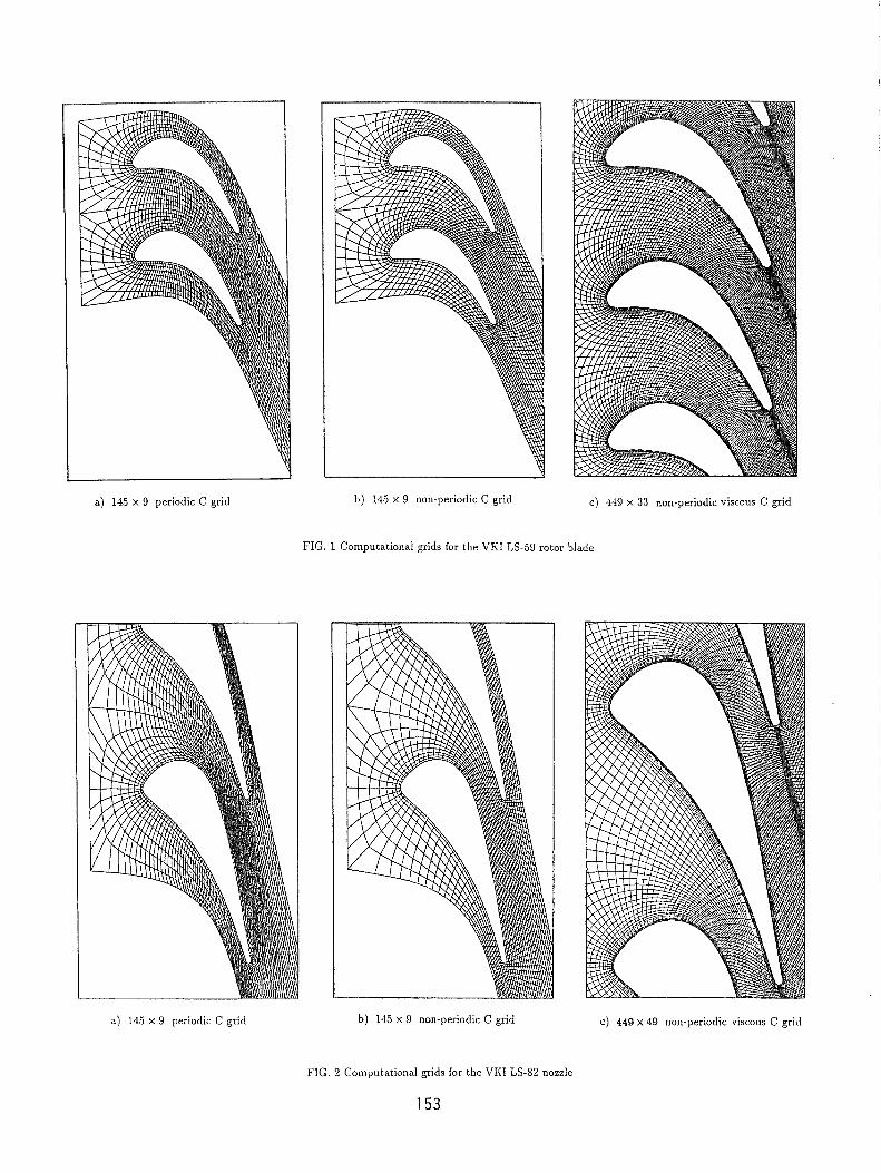
Some applications of the computational procedure that has been briefly described are pre- sented in this section. Numerical results are given for a rotor gas turbine blade (fig. 1) and for a
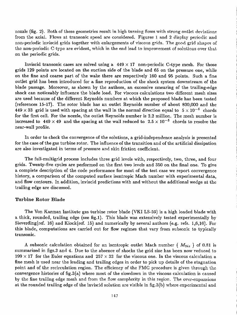
nozzle (fig. 2). Both of these geometries result in high turning flows with strong outlet deviations from the axial, Flows at transonic speed are considered. Figures 1 and 2 display periodic and non-periodic inviscid grids together with enlargements of viscous grids. The good grid shapes of the non-periodic C-type are evident, which in the end lead to improvement of solutions over that on the periodic grids.
Inviscid transonic cases are solved using a 449 x 17 non-periodic C-type mesh. For those grids 129 points are located on the suction side of the blade and 65 on the pressure one, while on the fine and coarse part of the wake there are respectively 160 and 95 points. Such a fine outlet grid has been introduced for a fine reproduction of the shock system downstream of the blade passage. Moreover, as shown by the authors, an excessive smearing of the trailing-edge shock can noticeably influence the blade load. For viscous calculations two different mesh sizes are used because of the different Reynolds numbers at which the proposed blade has been tested (references 15-17). The rotor blade has an outlet Reynolds number of about 800,000 and the 449 x 33 grid is used with spacing at the wall in the normal direction equal to 5 x chords for the first cell. For the nozzle, the outlet Reynolds number is 2.2 million. The mesh number is increased to 449 x 49 and the spacing at the wall reduced to 2.5 x chords to resolve the near-wall profile.
In order to check the convergence of the solutions, a grid-independence analysis is presented for the case of the gas turbine rotor. The influence of the transition and of the artificial dissipation are also investigated in terms of pressure and skin friction coefficient.
The full-multigrid process includes three grid levels with, respectively, two, three, and four grids. Twenty-five cycles are performed on the first two levels and 350 on the final one. To give a complete description of the code performance for most of the test case we report convergence history, a comparison of the computed surface isentropic Mach number with experimental data, and flow contours. In addition, inviscid predictions with and without the additional wedge at the trailing edge are discussed.
Turbine Rotor Blade
The Von Karman Institute gas turbine rotor blade (VKI LS-59) is a high loaded blade with a thick, rounded, trailing edge (see fig.1). This blade was extensively tested experimentally by Sieverding(ref. 16) and Kiock(ref. 15) and numerically by several authors (e.g. refs. 1,6,16). For this blade, computations are carried out for flow regimes that vary from subsonic to typically transonic.
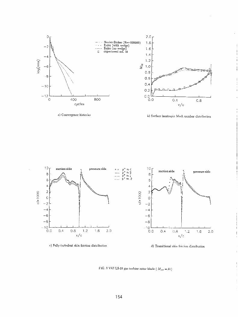
A subsonic calculation obtained for an isentropic outlet Mach number ( M2;, ) of 0.81 is summarized in figs.3 and 4. Due to the absence of shocks the grid size has been now reduced to 199 x 17 for the Euler equations and 257 x 33 for the viscous one. In the viscous calculation a fine mesh is used near the leading and trailing edges in order to pick up details of the stagnation point and of the recirculation region. The efficiency of the FMG procedure is given through the convergence histories of fig.3(a) where most of the slowdown in the viscous calculation is caused by the fine trailing edge mesh and from the flow complexity in this region. The over-expansions at the rounded trailing edge of the inviscid solution are visible in fig.3(b) where experimental and
computed surface isentropic Mach number are compared. For this case no important difference in terms of pressure distribution is noticed between the fully turbulent and transitional solution.
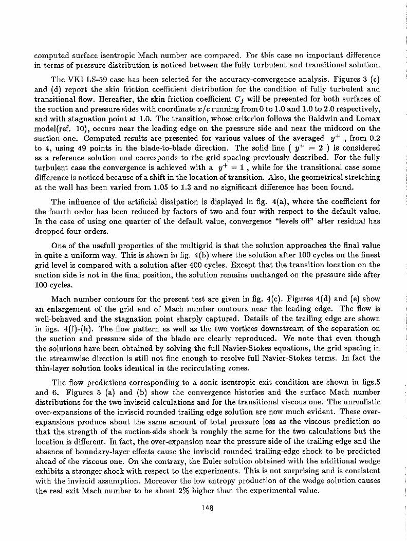
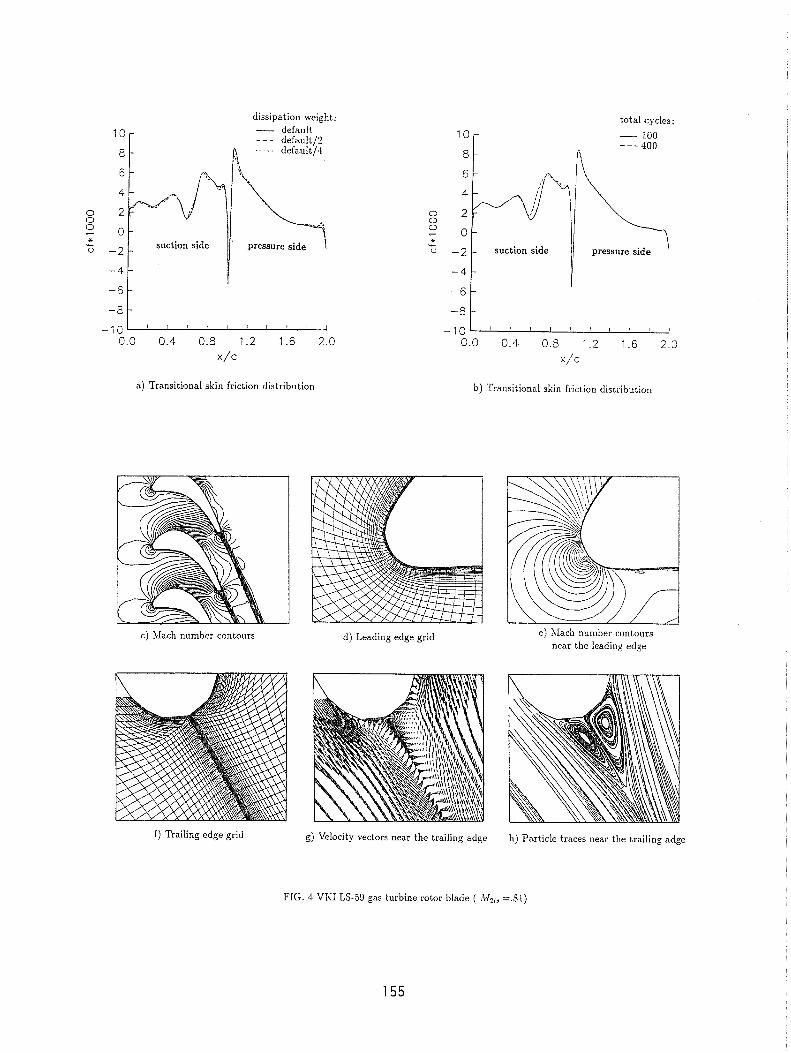
The VKI LS-59 case has been selected for the accuracy-convergence analysis. Figures 3 (c) and (d) report the skin friction coefficient distribution for the condition of fully turbulent and transitional flow. Hereafter, the skin friction coefficient Cf will be presented for both surfaces of the suction and pressure sides with coordinate x / c running from 0 to 1.0 and 1.0 to 2.0 respectively, and with stagnation point at 1.0. The transition, whose criterion follows the Baldwin and Lomax model(ref. lo), occurs near the leading edge on the pressure side and near the midcord on the suction one. Computed results are presented for various values of the averaged y+ , from 0.2 to 4, using 49 points in the blade-to-blade direction. The solid line ( y+ = 2 ) is considered as a reference solution and corresponds to the grid spacing previously described. For the fully turbulent case the convergence is achieved with a y+ = 1 , while for the transitional case some difference is noticed because of a shift in the location of transition. Also, the geometrical stretching at the wall has been varied from 1.05 to 1.3 and no significant difference has been found.
The influence of the artificial dissipation is displayed in fig. 4(a), where the coefficient for the fourth order has been reduced by factors of two and four with respect to the default value. In the case of using one quarter of the default value, convergence "levels ofP' after residual has dropped four orders.
One of the useful1 properties of the multigrid is that the solution approaches the final value in quite a uniform way. This is shown in fig. 4(b) where the solution after 100 cycles on the finest grid level is compared with a solution after 400 cycles. Except that the transition location on the suction side is not in the final position, the solution remains unchanged on the pressure side after 100 cycles.
Mach number contours for the present test are given in fig. 4(c). Figures 4(d) and (e) show an enlargement of the grid and of Mach number contours near the leading edge. The flow is well-behaved and the stagnation point sharply captured. Details of the trailing edge are shown in figs. 4(f)-(h). The flow pattern as well as the two vortices downstream of the separation on the suction and pressure side of the blade are clearly reproduced. We note that even though the solutions have been obtained by solving the full Navier-Stokes equations, the grid spacing in the streamwise direction is still not fine enough to resolve full Navier-Stokes terms. In fact the thin-layer solution looks identical in the recirculating zones.
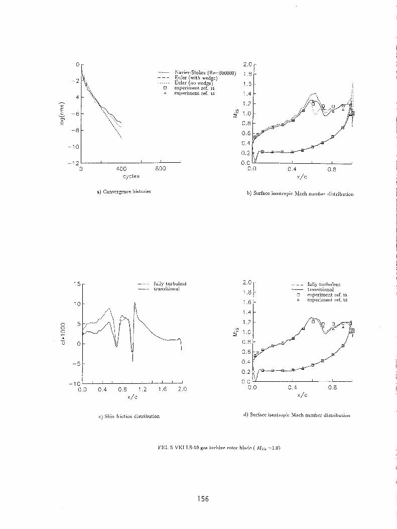
The flow predictions corresponding to a sonic isentropic exit condition are shown in figs.5 and 6. Figures 5 (a) and (b) show the convergence histories and the surface Mach number distributions for the two inviscid calculations and for the transitional viscous one. The unrealistic over-expansions of the inviscid rounded trailing edge solution are now much evident. These over- expansions produce about the same amount of total pressure loss as the viscous prediction so that the strength of the suction-side shock is roughly the same for the two calculations but the location is different. In fact, the over-expansion near the pressure side of the trailing edge and the absence of boundary-layer effects cause the inviscid rounded trailing-edge shock to be predicted ahead s f the viscous one. On the contrary, the Euler solution obtained with the additional wedge exhibits a stronger shock with respect to the experiments. This is not surprising and is consistent with the inviscid assmption. Moreover the low entropy production of the wedge solution causes the real exit Mach number to be about 2% higher than the experimental value.
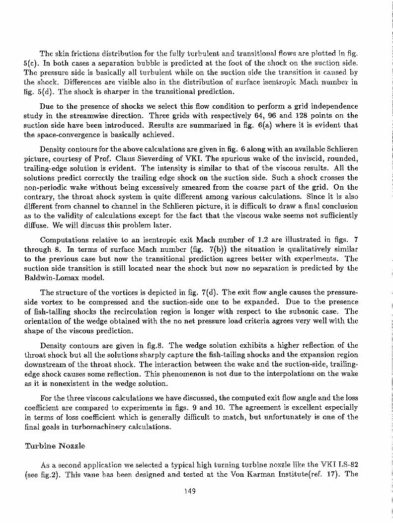
The skin frictions distribution for the fully turbulent and transitional flows are plotted in fig. 5(c). In both cases a separation bubble is predicted at the foot of the shock on the suction side. The pressure side is basically all turbulent while on the suction side the transition is caused by the shock. Differences are visible also in the distribution of surface isentropic Mach number in fig. 5(d). The shock is sharper in the transitional prediction.
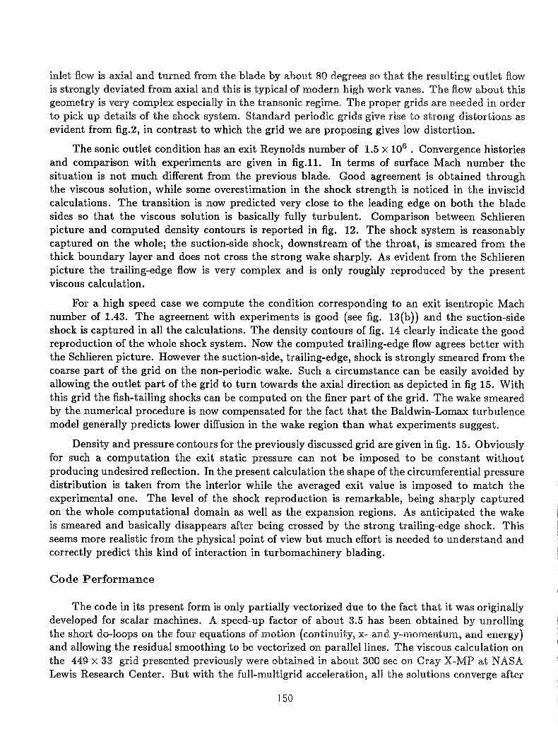
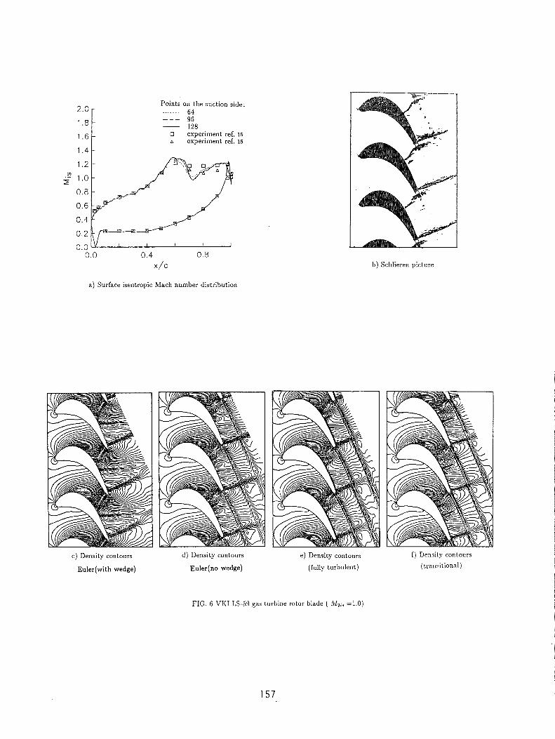
Due to the presence of shocks we select this flow condition to perform a grid independence study in the streamwise direction. Three grids with respectively 64, 96 and 128 points on the suction side have been introduced. Results are summarized in fig. 6(a) where it is evident that the space-convergence is basically achieved.
Density contours for the above calculations are given in fig. 6 along with an available Schlieren picture, courtesy of Prof. Claus Sieverding of VKI. The spurious wake of the inviscid, rounded, trailing-edge solution is evident. The intensity is similar to that of the viscous results. All the solutions predict correctly the trailing edge shock on the suction side. Such a shock crosses the non-periodic wake without being excessively smeared from the coarse part of the grid. On the contrary, the throat shock system is quite different among various calculations. Since it is also different from channel to channel in the Schlieren picture, it is difficult to draw a final conclusion as to the validity of calculations except for the fact that the viscous wake seems not sufficiently diffuse. We will discuss this problem later.
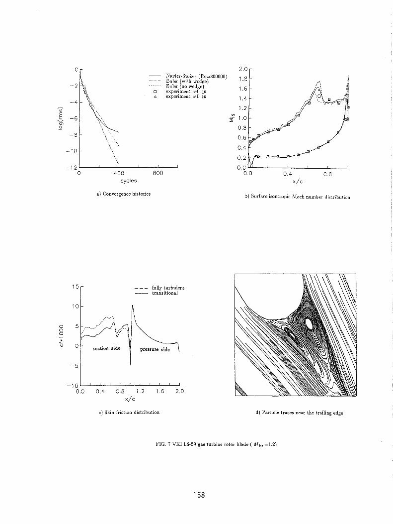
Computations relative to an isentropic exit Mach number of 1.2 are illustrated in figs. 7 through 8. In terms of surface Mach number (fig. 7(b)) the situation is qualitatively similar to the previous case but now the transitional prediction agrees better with experiments. The suction side transition is still located near the shock but now no separation is predicted by the Baldwin-Lomax model.
The structure of the vortices is depicted in fig. 7(d). The exit flow angle causes the pressure- side vortex to be compressed and the suction-side one to be expanded. Due to the presence of fish-tailing shocks the recirculation region is longer with respect to the subsonic case. The orientation of the wedge obtained with the no net pressure load criteria agrees very well with the shape of the viscous prediction.
Density contours are given in fig.8. The wedge solution exhibits a higher reflection of the throat shock but all the solutions sharply capture the fish-tailing shocks and the expansion region downstream of the throat shock. The interaction between the wake and the suction-side, trailing- edge shock causes some reflection. This phenomenon is not due to the interpolations on the wake as it is nonexistent in the wedge solution.
For the three viscous calculations we have discussed, the computed exit flow angle and the loss coefficient are compared to experiments in figs. 9 and 10. The agreement is excellent especially in terms of loss coefficient which is generally difficult to match, but unfortunately is one of the final goals in turbomachinery calculations.
Trsrbine Nozzle
As a second application we selected a typical high turning turbine nozzle like the VKI LS-82 (see fig.2). This vane has been designed and tested at the Von Karman Institute(ref. 17). The
inlet flow is mial and turned from the blade by about 80 degrees so that the resulting outlet flow is strongly deviated from axial and this is typical of modern high work vanes. The flow about this geometry is very complex especially in the transonic regime. The proper grids are needed in order to pick up details of the shock system. Standard periodic grids give rise to strong distortions as evident from fig.2, in contrast to which the grid we are proposing gives low distortion.
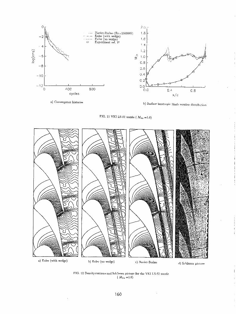
The sonic outlet condition has an exit Reynolds number of 1.5 x lo6 . Convergence histories and comparison with experiments are given in fig.11. In terms of surface Mach number the situation is not much different from the previous blade. Good agreement is obtained through the viscous solution, while some overestimation in the shock strength is noticed in the inviscid calculations. The transition is now predicted very close to the leading edge on both the blade sides so that the viscous solution is basically fully turbulent. Comparison between Schlieren picture and computed density contours is reported in fig. 12. The shock system is reasonably captured on the whole; the suction-side shock, downstream of the throat, is smeared from the thick boundary layer and does not cross the strong wake sharply. As evident from the Schlieren picture the trailing-edge flow is very complex and is only roughly reproduced by the present viscous calculation.
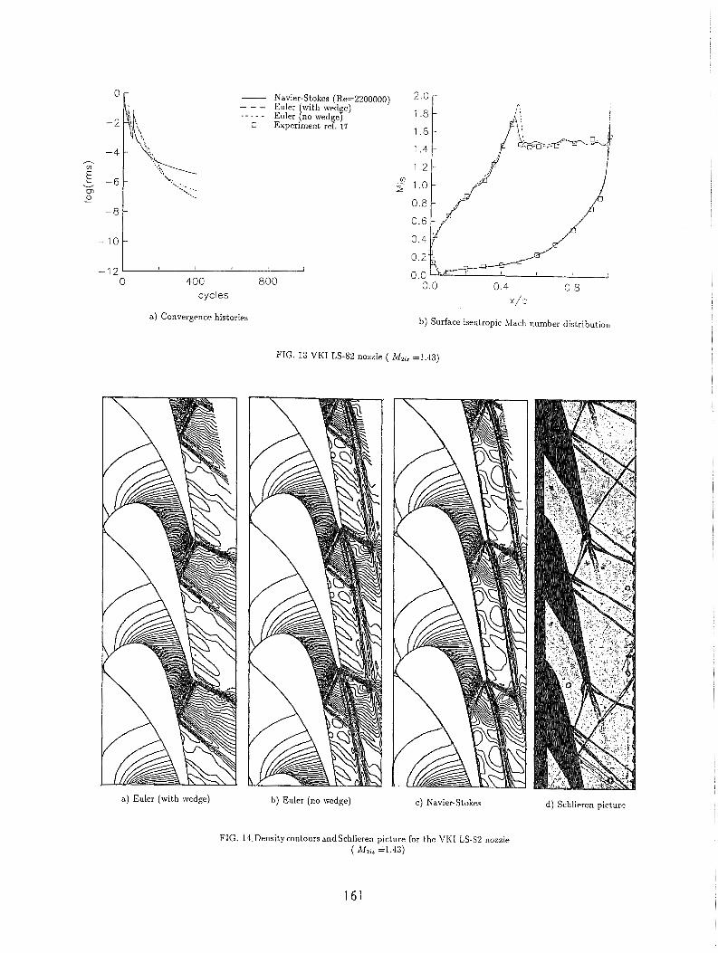
For a high speed case we compute the condition corresponding to an exit jsentropic Mach number of 1.43. The agreement with experiments is good (see fig. 13(b)) and the suction-side shock is captured in all the calculations. The density contours of fig. 14 clearly indicate the good reproduction of the whole shock system. Now the computed trailing-edge flow agrees better with the Schlieren picture. However the suction-side, trailing-edge, shock is strongly smeared from the coarse part of the grid on the non-periodic wake. Such a circumstance can be easily avoided by allowing the outlet part of the grid to turn towards the axial direction as depicted in fig 15. With this grid the fish-tailing shocks can be computed on the finer part of the grid. The wake smeared by the numerical procedure is now compensated for the fact that the Baldwin-Lomax turbulence model generally predicts lower diffusion in the wake region than what experiments suggest.
Density and pressure contours for the previously discussed grid are given in fig. 15. Obviously for such a computation the exit static pressure can not be imposed to be constant without producing undesired reflection. In the present calculation the shape of the circumferential pressure distribution is taken from the interior while the averaged exit value is imposed to match the experiment a1 one. The level of the shock reproduct ion is remarkable, being sharply captured on the whole computational domain as well as the expansion regions. As anticipated the wake is smeared and basically disappears after being crossed by the strong trailing-edge shock. This seems more realistic from the physical point of view but much effort is needed to understand and correctly predict this kind of interaction in turbomachinery blading.
Code Performance
The code in its present form is only partially vectorized due to the fact that it was originally developed for scalar machines. A speed-up factor of about 3.5 has been obtained by unrolling the short ds-loops on the four equations of motion (continuity, x- and y-momentum, and energy) and allowing the residual smoothing to be vectorized on parallel lines. The viscous calculation on the 449 x 33 grid presented previously were obtained in about 300 sec on Gray X-MP at NASA Lewis Research Center. But with the full-multigrid acceleration, all the solutions converge after
200 cycles, which take PPO sec on NAS Gray Y-NIP. For design applications a subsonic solution on a 25'7 x 33 grid converges after about 53 mrrltigrid cycles on the fiiiest grid level (four decade drops in the residual) and this can be obtained in 33 sec on the Gray X-MP.
CONCLUSIONS
A new kind of C-type grid has been introduced, this grid is non-periodic on the wake and allows very good flow predictions for cascades with high turning and large camber. The central difference finite volume scheme with artificial dissipation originally developed for external flows has proven to be accurate and to converge well for cascade viscous flows. With the described accelerating strategies, accurate transonic viscous solutions can be obtained in less than two minutes on a modern supercomputer. Good overall prediction can be obtained with the Baldwin- Lomax turbulence model. However in transonic turbine blading the trailing-edge flow is very complex and strongly influences the whole flowfield so that additional effort is needed, especially in turbulence modelling in order to obtain detailed and realistic flow simulations. An appropriate prediction of the wake and of the transition are other important topics that require further development.
ACKNOWLEDGMENT
All the schlieren pictures reported in this paper are provided by Prof. Claus Sieverding who is gratefully acknowledged.
REFERENCES
1. Ni, R. H.,"Multiple-Grid Scheme for Solving the Euler Equations," AIAA Journal, 20, 1565- 1571(1981).
2. Holmes, D. G., and Tong, S. S.,"A Three-Dimensional Euler Solver for Turbomachinery Blade Rows," Transaction of the ASME, 107, 258-264(1985).
3. Chima, R. V.,"Inviscid and Viscous Flows in Cascades with an Explicit Multiple-grid Algo- rithm," AIAA Journal, 23, 1556-1563(1985).
4. Hah, C., and Selva, R. J.,"Navier-Stokes Analysis of Flow and Heat Transfer Inside High- Pressure-Ratio Turbine Blade Rows," AIAA Paper 90-0343 (1990).
5. Nakahashi, K., Nozaki, O., Kikuchi, K., and Tamura, A., "Navier-Stokes Computations of Two- and Three-Dimensional Cascade Flowfields," Journal of Propulsion and Power, 5, 320-326(1989).
6. Arnone, A., and Swanson, R. C.,"A Navier-Stokes Solver for Cascade Flows,", NASA CR 181682(1988).
7. Sorenson, R. L.,"A Computer Program to Generate Two-Dimensional Grids About Airfoils and Other Shapes by the Use of Poisson's Equation," NASA TM 81198, 1980.
8. Steger , J. L., and Sorrenson, R. L., ""Automatic Mesh-Point Clustering Near a Boundary in Grid Generat ion with Elliptic Partial Differential Equations," Journal of Computational Physics, 33, 405-410(1979).
9. Jameson, A., Schmidt, W., and Turkel, E.,66Numerical Solutions of the Euler Equations by Finite V~1ume Methods Using Rungc-Kutta Timestepping Schemes," AIAA Paper 81- 1259(1981).
10. Baldwin, B. S., and Lornax, W.,"bThin Layer Approximation and Algebraic Model for Sepa- rated Turbulent Flows ," AIA A Paper 78-0257(1978).
11. Swanson, R. C., and Turkel, E., '"Artificial Dissipation and Central Difference Schemes for the Euler and Navier-Stokes Equations," AIAA Paper 87-1 107(1987).
12. Arnone, A., and Stecco, S. S., "Inviscid Cascade Flow Calculations Using a Multigrid Method," ASME Turbo Expo, Toronto,l989.
13. Martinelli, L., "Calculations of Viscous Flows with a Multigrid Method," Ph.D . dissertation, MAE Department, Princeton University(l983).
14. Jameson, A.,"Transonic Flows Calculations," MAE Report 1651, Princeton University (1983). 15. Kiock, R., Lehthaus, F., Baines, N. C., and Sieverding, C. H., "The Transonic Flow Through
a Plane Turbine Cascade as Measured in Four European Wind Tunnels," Journal of Engi- neering for Gas Turbines and Power, 108, 277-285(1986).
16. Sieverding, C. H.,"Experimental Data on Two Transonic Turbine Blade Sections and Com- parison with Various Theoretical Methods," VKI Report, LS59(1973).
17. "Workshop on 2D and 3D Flow Calculations in Turbine Bladings,", VKI Report, LS82- 05 (1982).
L
a) 145 x 9 periodic C grid
a) 145 x 9 periodic C grid
b) 145 x 9 non-periodic C grid c) 449 x 33 non-periodic viscous C grid
FIG. 1 Computational grids for the VKI LS-59 rotor blade
b) 145 x 9 non-periodic C grid c) 449 x 49 non-periodic viscous C grid
FIG. 2 Computational grids for the VI<I LS-82 nozzle
153
0 400 800 cycles
a) Convergence histories
- - - - Euler Navier-Stokes with wedge) (Re=SOOOOO) y!i 1 ..-.- Euler {no wedge) n experiment ref. 15
1.4
b) Surface isentropic Mach number distribution
c) Fully-turbulent skin friction distribution d) Transitional skin friction distribution
1 0 suction side : pressure side o o V+ x 4 10 -
FIG. 3 VI<I LS-59 gas turbine rotor blade ( ihi3 =.S1)
- y f e 2 8 suction side Z pressure side
- 3 r v
6 - 6 -
0 2 - 0 R
=I 0- 2 0 - * - - 0 -2 - -2 -
-4 - -4 -
-6
-8
- -6 -
- i l ! f ! l -8 - -10 -10 ' ' ' ' 0.0 0.4 0.8 1.2 1.6 2.0 0.0 0.4 0.8 1.2 1.6 2.0
x/c x/c
dissipation weight:
1 0 - default -- - default/:! ....- default14
4
suction side .
0 -2 pressure side
- 4
- 6
a) Transitional skin friction distribution
total cycles:
- 100
b) Transitional skin friction distribution
c) Mach number contours d) Leading edge grid e) Mach number contours near the leading edge
f ) Trailing edge grid g) Velocity vectors near the trailing adge h) Particle traces near the trailing adge
FIG. 4 VIiI LS-59 gas turbine rotor blade ( 1\42,, =.Sl)
- 1 2 1 1 I 1 I I
0 400 800 cycles
- Navier-Stokes (Re=S00000) 1 . 8 - - - Euler with wedge) ...... Euler [no wedge) 1.6
experiment ref. 15 A experiment ref. 15 1.4 -
a) Convergence histories
-
-
,--> I , .. . .. .
--- fully turbulent - transitional
1 . 2 -
0.0 0.4 0.8
x/c
b) Surface isentropic Mach number distribution
- - - fully turbulent - transitional
@ experiment ref. 15 a experiment ref. 15
c) Skin friction distribution d) Surface isentropic Mach number distribution
FIG. 5 VI<I LS-59 gas turbine rotor blade ( 11.12;~ =1.0)
Points on the suction side: 2.0 r ....... 64
. . - - - 96 - 128
experiment ref. 15 n experiment ref. 15
a) Surface isentropic Mach number distribution
c) Density contours
Euler(with wedge)
b) Schlieren picture
d ) Density contours e ) Density contours
Euler(no wedge) (fully turbulent)
FIG. 6 VI<I LS-.59 gas turbine rotor blade ( iLI,;, =1.0)
f ) Density contours
(transitional)
2.0 - Navier-Stokes (Re=S00000) --- Euler with wed e) 1.8 -----. Euler [no vedgeP
1.6 experiment ref. 16 a experiment ref. 16 1.4
1.2 V) 5 1.0
0.8
0.6
0.4
0.2
0 400 800 cycles
a) Convergence histories
--- fully turbulent - transitional
b) Surface isentropic Mach number distribution
c ) Skin friction distribution d) Particle traces near the trailing edge
FIG. 7 VI<I LS-59 gas turbine rotor blade ( i%ir =1.3)
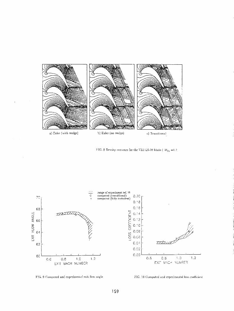
a) Euler (wi th wedge) b) Euier (no wedge) c) Transitional
FIG. S Density contours for the VIiI LS-90 blade ( .\I2,, =I,?;
- - range of esperiment ref. 15 c computed (transitional) 0 . 2 0 A computed (fully-turbulent)
0 . 1 8 F
60 " " " "
0.6 0.8 1 .O 1.2 EXIT MACH NUMEER
FIG. 9 Cornpr~ted and experimental exit flow angle FIG. 10 Computed and experimental loss coefficient
cycles
2.0 -
a) Convergence histories
------- Navier-Stokes (Re=l500000) 1 .B - - - Euler with wedge) ----.. Euler [no wedge) 1.6
0 Experiment ref. 17 1.4
a) Euler (with wedge)
-
-
-
b) Surface isentropic Mach number distribution
0.0 0.4 0.8
x / C
FIG. 11 VI<I LS-82 nozzle ( ill2;, =1.0)
b) Euler (no wedge) c) Navier-Stokes d ) Schlieren picture
FIG. 12 Densitycontoursand Schlieren picture for the VI<I LS-S2 nozzle ( Mzi, =1.0)
- Navier-Stokes (Re=2200000) - - - Euler with wed e) - - - - - Euler [no ivedgef
E Experiment ref. 17 1.6
1.4
-12 , I I , I
0 400 800 cycles
a) Convergence histories
x/:
b) Surface isentropic Mach number distribution
FIG. 13 VKI LS-S2 nozzle ( ibf2is =1.43)
a) Euler (with wedge) b) Euler (no wedge) C) Navier-Stokes d) Schlieren picture
FIG. 14,Densitycontours andschlieren picture for the VI i I LS-52 nozzle ( hf2i3 ~ 1 . 4 3 )
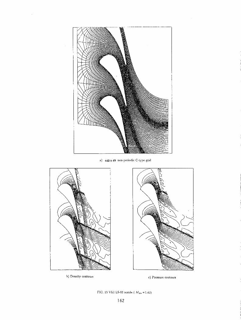
a) 449 x 49 non-periodic C-type grid
b) Density contours c) Pressure contours
FIG. 15 VI<I LS-S2 liozzle ( I&,, =1.43)
162