Embed Size (px)
Citation preview

Using Ontologies to Simplify Wireless Network Configuration
David Cleary1* Boris Danev1
Diarmuid O' Donoghue2
[email protected] Voice: +353 9064 31579 Fax: +353 9064 31304
1Applied Research Labs, Ericsson Ireland,
Ericsson Software Campus, Athlone,
Co. Westmeath, Ireland.
2Department. of Computer Science, NUI Maynooth, Ireland.
Maynooth, Co. Kildare, Ireland.
Abstract
Today’s global telecommunication infrastructure is growing in complexity, making it more difficult to
manage and operate effectively. In this paper we examine the problems of simplifying configuration
tasks and thus reducing operating expenditure (OPEX) for wireless telecom operators. Our approach is
to use ontologies to capture networking information as well as the domain and expert knowledge
needed for network configuration tasks. After semantically enriching the representation of the radio
access network model, we will show how complex configuration tasks that manipulate the existing
network models can be simplified. Furthermore we show how task complexity can be reduced by the
use of formal ontologies.
Formal Ontologies Meet Industry, Verona, Italy, June 9-10, 2005.

1 Introduction Since the early formalization of network management [14] as a discipline, many derivations and
simplifications of the ideas have been proposed [4] [13] [17] [21]. For the most part these approaches
have differentiated themselves by suggesting the use of “improved” syntactical protocols and
processing models. This is an adequate (though not ideal) approach for two key areas, fault
management and performance management. However when we talk about configuration management
or provisioning, this approach proves to be inadequate. Configuration management relies on a full
understanding of the network topology and state, such that a specific task can be addressed. Today, we
rely on human and expert knowledge to fill this gap and configure our networks. This inability to create
value added configuration applications stems from the lack of agreement on or the definition of, formal
semantics needed for configuration activities.
Abstractly, network management can be thought of as an observer function, normally referred to as a
management station, which communicates with probes, normally referred to as agents, in a piece of
networking equipment. Different approaches in the cardinality, data abstraction and hierarchical nature
of relationships often results in different software implementations.
If we look at the problems that are related to knowledge sharing, reuse and reasoning about
information, we can see analogies within configuration management. In the wider research community
much work is ongoing in this fledgling field. There are specific fields, even in computer science, which
have successfully developed like knowledge based systems. The complexity of such systems prevents
them from being used in general, and the lack of standardization, modelling, and reasoning tools
undermines their future development. With the Semantic web initiative [2] ontology development
regained life and attracted attention from the fast growing web community.
An ontology is a hierarchy of organised concepts, relations among them (in addition to is-a or part-of)
and axioms to formalize the definitions and relations. Ontology based models allow reasoning through
formal semantics, which can be understood by machines. We believe that ontologies have the potential
to solve challenging problems in configuration management such as creating richer managed-object
models of networks, while allowing more automation in detection of bad configuration and
reconfiguration situations. This facilitates the creation of better business contracts between network
elements and management stations to achieve a particular task through operator workflows [5].
At present, model manipulation in network management is based on manipulating data from network
elements to facilitate the following [14] taxonomy of management. Network management models are
generally based on a set of object-oriented models that raise the abstraction from physical resources to
a higher level of abstraction that can be used by software management applications. These applications
control the model by creating, modifying and deleting objects. The Managed Object Model (MOM) can
be expressed in UML Class Models, with containment and association relations between Managed
Objects being used to capture the interoperability of Managed Objects.
In the rest of this paper we will introduce the problem domain of configuration management in third
generation wireless networks. Then we will give a brief overview of today’s standard approach.
Finally, our use of formal ontologies using a case study of reconfiguring a 3G radio network is
presented.
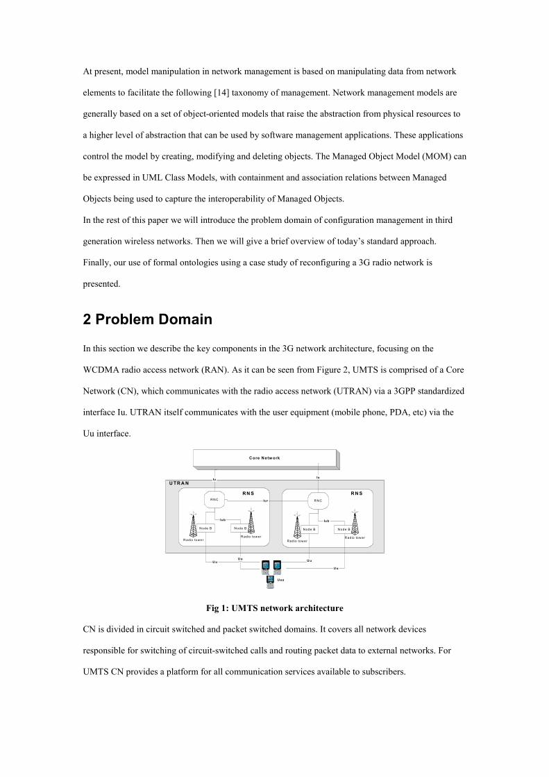
2 Problem Domain In this section we describe the key components in the 3G network architecture, focusing on the
WCDMA radio access network (RAN). As it can be seen from Figure 2, UMTS is comprised of a Core
Network (CN), which communicates with the radio access network (UTRAN) via a 3GPP standardized
interface Iu. UTRAN itself communicates with the user equipment (mobile phone, PDA, etc) via the
Uu interface.
Core Network
RNC
Node B
Radio towe r
Node B
Radio tower
Iub
UuUu
RNC
Node B
Radio tower
Node B
Radio tower
Iub
Uu
Uu
Iur
IuIu
Ues
RNS RNS
UTRAN
Fig 1: UMTS network architecture
CN is divided in circuit switched and packet switched domains. It covers all network devices
responsible for switching of circuit-switched calls and routing packet data to external networks. For
UMTS CN provides a platform for all communication services available to subscribers.

UTRAN (Universal Terrestrial RAN) is the UMTS radio access technology. It is composed of Radio
Network Subsystems (RNS). The switching and controlling entity in the RNS is the Radio Network
Controller (RNC). The RNCs control the allocation and the release of specific radio resources and are
connected via the open interface Iur. Each RNC manages via the Iub standard interface a number of
Node Bs. The Node B handles the radio communication with the user equipment (UE). UE can be any
wireless device enabled to access the radio network, such as mobile phones, PDAs, etc. Consider the
following operation on a typical network based on increase demand.
Given a metropolitan area with one radio network controller (RNC) and many radio base
stations (RBS) in the North. The operator decides to expand the WCDMA network in the
South. It starts putting new radio base stations in the South and parents them to the RNC in
the North. During the expansion of the network, it becomes apparent that a new RNC will be
needed in the South. The operator purchases a new RNC, installs it in the South and proceeds
to move control (reparent) all RBSs located in the South to the newly installed RNC.
The task involves two Radio Network Subsystems (RNS), one called source RNS and the other target
RNS. Each RNS consists of an RNC (Radio Network Controller) and a number of Node Bs controlled
by this RNC. The reparenting process consists of moving control of a Node B from the source RNS to
the target RNS. This means creating control structures for the source Node B in the target RNS and
deleting existing control structures in the source RNS without physically changing the location of the
Node B.
Moving control from one RNS to another means building the standard protocol Iub, Mub and Aal2
links on the target RNC side. Each interface consists of a protocol stack. Reparenting Node B requires
complex reconfiguration in three separate areas: ATM Transport Network, Radio Network and IP
Network. This reconfiguration must be well planned and executed carefully following a big number of
constraints represented in task workflows. Later in this paper, we will show how this reparenting task
can be largely automated with the use of ontologies.
3 Current Management Models and Manipulation Techniques From a configuration management perspective in the context of third generation radio systems, the
information model that holds the information is accessible via a standardized CORBA interface [21]

and not IETF’s SNMP [23]. The Managed Object Model ( MOM) is part of the management adaptation
layer. The MOM is actually a UML model of the interface used by the network manager to manage a
number of network elements. A central point in the MOM is the Managed Object (MO). The MO is an
abstraction of some managed entity, such as a hardware resource, a mobile cell, or a communication
channel. A manager controls an entity by creating, deleting, and modifying MOs that represent that
entity. The main advantage of the MOM is that it follows the OO paradigm and thus is well structured
and comprehensive. The management paradigm for all MOs is generic, irrespective of the entity that
the MO represents. It is also possible to generate forms for all MOs by using the model information,
making it possible to browse the model and to view and edit any MO.
Each network element has what is called a Managed Information Base (MIB). This is a container of
MOs with concrete instances of Managed Objects, with relationships between them according to the
rules in the MOM UML diagram. The Managed Object naming mechanisms consist of relative
distinguished name (RDN), local distinguished name (LDN) and fully distinguished name (FDN). A
MO’s RDN is a name relative to a parent object, LDN is relative to the top object in local MIB and
FDN is relative to the top object in particular domain. Managed Objects can be addressed with scope
and filter parameters, which allow more than one MO to be addressed simultaneously. This is useful for
performing searches of MOs with particular attributes or for performing operations on sets of MOs of
certain types. MOs often have state, which is modelled in state attributes on the MOs in question.
3.1 Limitation of MOM in UML
Because of the informal semantics enforced in commercial UML modelling tools, expressing MOM
structures in UML does not allow smart machine processing. When exploring the MOM in WCDMA,
it can be seen that some knowledge is expressed in natural language. The list below gives two brief
examples.
i) Specifying invariants on attributes in the MOM. E.g. The Signaling ATM Adaptation
Layer (SAAL) for use with ATM UNI specifies that congestion related attributes must be
in a certain range.
ii) Specifying constraints between attributes in the same MO. E.g. SAAL for use with ATM
UNI specifies that different congestion level attributes must follow a rule of type: 0<=
congestionLevel1 <= congestionLevel2 <= 100.

Extra constraints can be expressed in UML by using OCL (Object Constraint language) to annotate the
model. OCL provides a syntax to specify invariants on classes and types, to describe guards and specify
constraints on operations. This may lead to ambiguities, thus OCL relies on many primitives from the
well-understood semantics of formal languages but the syntax is more human readable. Another issue
with this approach is the runtime view or the mapping of the OCL constructs into instance objects.
As a result, consistency control needs to be performed separately from the model in many cases. This
means that knowledge moves outside the model into another application. Interoperability of MOMs is
difficult as they have proprietary aspects, thus it is problematic to exchange or integrate Managed
Object information between vendors. Using UML and OCL limits us to modelling only the MOs that
are common between vendors, thus it still does not let us represent vital semantic information.
4 A Ontological approach to Telecom Modelling In this section we describe a new ontology-based modelling approach applicable to the wireless
network configuration area. This approach tries not only to improve the current modelling, as expressed
in the managed object models, but also strives to apply ontologies in modelling more complex
configuration tasks that require domain and expert knowledge.
In order to achieve our modelling objectives, we designed an ontology centric management system for
configuration applications. The overall architecture is depicted in Figure 2.
Fig 2: Ontology Centric Architecture
The architecture interacts with the current Network Management System and network resources via the
3GPP Bulk CM IRP standard [22]. The Bulk CM IRP provides an XML representation of configuration
data for use by external network management applications. The Bulk XML configuration data is then

used to build instances of the formal ontologies representing the domain and operational knowledge.
These instances are supplied to the reasoning (inference) engine, the core of our ontology centric
architecture. The inference engine’s function is to control the configuration process by suggesting
possible configurations and validating the consistency and integrity of user configurations against the
knowledge base. After the configuration has been accomplished, a general consistency and integrity-
checking phase is performed to ensure that the entire configuration is legal with respect to the
knowledge base. Then the new configuration information inside the inference engine is converted again
in XML according to the Bulk CM IRP standard for deployment on the real network.
4.1 Modelling Objectives
We consider ontologies as a possible solution to represent the network management domain model and
integrate expert knowledge in configuration workflows, facilitating the engineering task. Central to our
new approach are the following key objectives.
i) Our new formal representation will be based on current standard ontologies, thus
facilitating model sharing and exchange as a key to solving the problem of
interoperability.
ii) Our ontologies will allow for modelling of configuration task workflows, and thus
incorporate expert configuration knowledge into our management application.
iii) The semantically enriched model will allow different categories of user interaction such
as bulk unmanned background operation, Web portals, thick clients etc. . This is similar in
thinking to 3-tier client server approaches, with the difference being that our network
logic is enriched into the data tier.
iv) The models will help with consistency checking and validation at at run time, preventing
errors, mis-configurations and inconsistencies.
v) As our modelling techniques are based on declarative techniques, issues like versioning
can be easily handled with the interjection of rules.
vi) Perhaps the key benefit of this approach is that domain expertise in the Radio Access
Networks (RAN) can be captured and reused across value added applications,
independently of the OSS infrastructure and the presentation environment.

4.2 Modelling approach
After analyzing the problem domain, we found that the concepts encapsulated in the Managed Object
Models are rather easy to express. There is no complex is-a inheritance hierarchy. All objects derive
from class Managed Object and the hierarchy finishes there. The entire model is a complex type of
“part-of” hierarchy, with cardinality constraints on the different parts of the model. Basically, it has
containment relationships such as “Object A contains object B” or the inverse “B is a part of A”, and
association relationships used to define relationships between objects. The model is completely object
oriented.
Description logic (DL) based languages support subsumption for classes, and are very helpful during
modelling in detecting new is-a relationships between classes, thus avoiding errors in modelling new
concepts. It is possible to use subsumption techniques for the part-of relationship, but there are issues
with current tools, such as FaCT++ being potentially combinatory explosive when dealing with part-of
hierarchies like medical anatomy ontologies. While being good at modelling, DLs do not seem to be
applicable for reasoning/querying in large sets of instances and thus cannot be used as a run-time
system for ontology-based applications based on the query-answer paradigm
Frame-logic based languages, on the other hand, also provide support for subsumption. [8] effectively
reducing subsumption reasoning to query answering, but DLs remain in general more efficient[20]. The
strength of F-logic languages comes from the fact that there are well-optimised implementations for
query answering such as Flora-2 and Ontobroker, which makes them a possible run-time environment
for ontology-based applications.
In the domain of telecom management there is a need for establishing business contracts in
configuration or reconfiguration applications. We also need interaction rules to represent the behaviour
of concepts and tasks from different MOMs. F-logic based languages have rules with well-studied
semantics integrated into the language itself. For DL based languages such as OWL, the need for rules
also exists, and there is currently a SWRL W3C recommendation, which integrates with OWL.
However at the time of our investigation, no proper SWRL implementations were available.
There is a trade-off between the inference power of the language and the ability to catch modelling
mistakes[6].

4.3 Manipulating Ontologies
Description logics [1] are a family of knowledge representation languages that can be used to represent
the knowledge of a domain in a structured and formally well-understood way. OWL DL follows this
modelling approach. Currently there are two optimized inference engines for reasoning about
Description Logics, which are RACER [10] and FaCT++ [18]. They both are pluggable to many
ontology-editing tools like Protégé. It is important to mention that an ontology editor is a graphical user
interface to create ontologies, but not an inference engine. Most of the ontology editors use third-party
inference engines to actually help with the modelling.
Frame logic (F-logic) [15] combines the advantages of the frame-based languages with the
expressiveness and well-defined semantics from logics. It is a deductive, object oriented database
language, which combines the declarative semantics and expressiveness of deductive database
languages with the rich data modelling capabilities supported by the oriented data model. There are
three well-optimised implementations of the F-logic paradigm that can be used for reasoning on
languages based on F-logic. These are FLORID [16] which is a research prototype; OntoBroker [3];
and FLORA–2 [19].
To obtain the most value from representing information in ontologies, it is important to infer
information or knowledge. There are two types of reasoning on ontologies: TBox (related to
terminology) and ABox (query answering).
i) TBox deals with reasoning tasks: Subsumption of C by D concept. Satisfiability of C
concept. Equivalence of C and D concepts. Disjointness of C and D concepts.
ii) ABox deals with answering queries over the knowledge base. There are two types of
queries called ground and open queries. The inference task consists of checking if a fact is
entailed by the knowledge base. An open query is a formula with free variables, and the
inference task consists of finding the values of the variables from the knowledge base.
Examples of queries are consistency checks, checks to see if something is an instance or a
concept, retrieval of individuals and attributes, etc.
5 Case Study: WCDMA RAN Configuration
In order to demonstrate our ideas of using ontologies as a modelling paradigm for network concepts
and relationships, we decided to take a configuration scenario from the WCDMA Radio Access

Network (RAN) as a case study - the reparenting task described in Section 2 above. Another
interesting aspect of the domain is that configuration and reconfiguration tasks in the RAN require
rather complex interactions between different network elements, which lead to a need for consistency
checking and validation. Consistency checking tasks typically involve expert knowledge, presenting an
excellent research topic on how to integrate this knowledge in some common modelling paradigm, with
the goal of aiding the engineer during configuration or reconfiguration tasks. We chose to investigate
our techniques of using ontologies for a specific reparenting reconfiguration task. Briefly, in this
process we move control connections (and possibly the traffic connections as well) from a source node
to a new destination.
We divided our formal ontology modelling into three logical parts. The first model captured the
network information for the configuration task. The second model described the specific protocol that
needed to be changed during the reconfiguration. Finally we represented the workflow needed to
complete the task in a separated ontology.
5.1 Enriching The Network Model
In the first ontology we modelled the network and corresponding equipment adding semantic
information, such as cardinality and complex relationships between entities.
A first modelling approach follows closely the UML Class model and looks like:
#ManagedElement[#logicalName=>xsd#STRING;
#hasIpSystem => #IpSystem;
#mincard@(hasIpSystem) -> 1;
#maxcard@(hasIpSystem) -> 1;
#hasTransportNetwork => #TransportNetwork;
#mincard@(hasTransportNetwork) -> 1;
#maxcard@(hasTransportNetwork) -> 1;
.
..
].
Fig 3: UML MO mapping to F-Logic
In this case the containment relationships between the IpSystem and TransportNetwork concepts to the
ManagementElement concept, respectively (hasIpSystem and hasTransportNetwork) and their
cardinality constraints are explicitly modelled using the appropriate F-logic primitives as shown in
Fig.3.
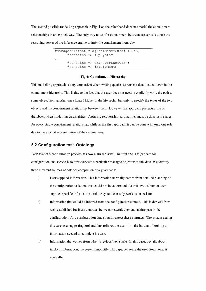
The second possible modelling approach in Fig. 4 on the other hand does not model the containment
relationships in an explicit way. The only way to test for containment between concepts is to use the
reasoning power of the inference engine to infer the containment hierarchy.
#ManagedElement[#logicalName=>xsd#STRING;
#contains => #IpSystem;
...
#contains => TransportNetwork;
#contains => #Equipment].
Fig 4: Containment Hierarchy
This modelling approach is very convenient when writing queries to retrieve data located down in the
containment hierarchy. This is due to the fact that the user does not need to explicitly write the path to
some object from another one situated higher in the hierarchy, but only to specify the types of the two
objects and the containment relationship between them. However this approach presents a major
drawback when modelling cardinalities. Capturing relationship cardinalities must be done using rules
for every single containment relationship, while in the first approach it can be done with only one rule
due to the explicit representation of the cardinalities.
5.2 Configuration task Ontology
Each task of a configuration process has two main subtasks. The first one is to get data for
configuration and second is to create/update a particular managed object with this data. We identify
three different sources of data for completion of a given task:
i) User supplied information. This information normally comes from detailed planning of
the configuration task, and thus could not be automated. At this level, a human user
supplies specific information, and the system can only work as an assistant.
ii) Information that could be inferred from the configuration context. This is derived from
well-established business contracts between network elements taking part in the
configuration. Any configuration data should respect these contracts. The system acts in
this case as a suggesting tool and thus relieves the user from the burden of looking up
information needed to complete his task.
iii) Information that comes from other (previous/next) tasks. In this case, we talk about
implicit information; the system implicitly fills gaps, relieving the user from doing it
manually.

#Task[#name => xsd#STRING;
#directPre =>> #Task;
#directPost =>> #Task;
#status => xsd#STRING;
#description =>> xsd#STRING]
Fig 5: Generic F-logic Task
A generic task is shown in Fig5 which comprises of a name, direct successor tasks, direct predecessor
tasks, status and a description. Each specific task of a configuration process inherits from this generic
task. Each task has a number of attributes that must be supplied; these closely map to the attributes of
managed objects the task will create or update. Each task has an internal link to empty managed
object(s). This is an explicit link between the MO and the task it is related to. It also has links to other
task objects indicating which information or related managed objects are needed to complete the
current task.
TransportTask[#atmPort =>
trans#AtmPort;
#vp => xsd#STRING;
#vci => xsd#STRING;
..
..
#atmTrafficDescriptorLink =>
trans#AtmTrafficDescriptor].
Fig 6: ATM Traffic Task
Fig6 expresses the configuration of a virtual path (VP) and a corresponding virtual channel (VCL). In
order to complete the configuration, this task must use data from the AtmTrafficDescriptor concept.
This is why there is an explicit link to that concept also. Its actual value is inferred from other tasks (in
this case AtmTrafficDescriptor task) which will bind to the #atmTrafficDescriptorLink
thanks to business contract rule.
5.3 Formal Rule
Finally in order to complete the modelling task, we created rules to establish the necessary business
contracts between tasks in order to make the process consistent and compliant to the required
configuration specification.
Basically we distinguish three types of rules; rules that are used to create new knowledge from existing
knowledge, rules that are used to establish business contracts between concepts such as managed

objects and tasks, and pure consistency checking rules such as cardinality constraint checking rules.
The second type of rules could be also called inference rules. Here are examples from the current
implementation:
i) New knowledge derivation rules. These rules are used to create new knowledge concepts
based on already existing knowledge. (Concept uncle could be modelled as my father’s
brother, as long as father and brother are known concepts). The following rules create a
new relationship “#pre” between two tasks and make the relationship transitive across
tasks.
FORALL T1,T2 T1[#pre ->> T2] <- T1[#directPre ->>
T2].
FORALL T1,T2,T3 T1[#pre ->> T3] <- T1[#pre ->>
T2] and T2[#pre ->> T3].
Fig 7: Derived Rule
The first rule in Fig. 7 models a new relationship #pre between two tasks derived from the
already existent knowledge about the relationship #directPre between the same tasks. The
second rule models the well-known transitive property, namely if Task 1 has a
relationship #pre to Task 2 and Task 2 has a relationship #pre to Task 3, this implies that
Task 1 has a relationship #pre to Task 3.
ii) Business contract rule: These rules connect concepts in a way that satisfies some specific
configuration requirement. They are not considered simply as checking rules because
their role is to transfer information from one concept to another. We also call them
inference rules.
FORALL Basestation,Controller,T,ID T[#baseID -> ID] <-
move(BaseStation,Controller,T) and T:ProtocolTask and
Basestation[#id -> ID].
Fig 8: WCMA Reconfiguration Rule
The rule described in Fig 8 infers the value of the #baseID attribute of the ProtocolTask T
from the BaseStation #id when there exists a particular relationship (move) between a
BaseStation, Controller and T. A direct consequence of this is that from a querying point
of view, the user should not bother to know from where to retrieve the value of the

attribute #baseID in a given configuration context. He just needs to query the owner of the
attribute, in this case the BaseStation, and the rest is left to the inference engine to find its
possible values.
iii) Pure constraint checking rules: These rules are most of the time used to constraint the
domain model itself.
FORALL S check(S) <- EXISTS R1,R2,V1,V2
R1::#BaseStation[#id -> V1] and R2::#BaseStation[#id ->
V2] and equal(V1,V2) and S is “We can not have two
BaseStations with same identity”.
Fig 9: Radio Network constraint
The rule in Fig 9 simply says that it is impossible to have two radio base stations with
same identity in a sub-network if we assume a sub-network context.
By using the above approach we have seen that we can dramatically reduce the amount of human
interaction needed for complex configuration operations. This ability to automate previously manual
tasks creates a more robust environment for wireless operator. Tasks once the sole domain of human
experts, due to the implicit knowledge needed to perform the tasks, can be carried out by less
knowledgeable technicians. Our approach removes steps in the configuration workflow that were
inherently prone to errors particularly in the area of the consistency of data values. A welcome side
effect is also the reduction in the time taken to carry out complex tasks. With the help of formal
ontologies we have significantly improved the workflow efficiency for reconfiguration of wireless
networks.
6 Conclusion In this paper we have shown the benefits of using Ontologies to help solve a complex real-world
network configuration problems. Our approach of augmenting network management models with
semantic knowledge coupled with workflows allows us to create new more powerful management
applications. Finally we presented an example of our approach in the domain of third generation
wireless network transport configuration. By adopting our techniques we are able to build more
intelligent management application that reduces wireless operators operation expenditure by the use of
formal ontologies.

7 Acknowledgements We would like to thank ontoprise® GmbH for their support and assistance during our prototyping
activities.
8 References
[1] F. Baader, Ian Horrocks and Ulrike Sattler, July 2003. Description Logics,
Handbook on Ontologies. International handbooks on Information systems.
Edition 2004.
[2] Tim Berner’s Lee et al. 2001. The Semantic Web, Scientific American, May 2001
[3] S. Decker, M. Erdmann, D. Fensel, and R. Studer. Ontobroker: Ontology Based Access to
Distributed and Semi-Structured Information. In DS-8: Semantic Issues in Multimedia Systems.
Kluwer, 1999.
[4] Distributed Management Task Force http://www.dmtf.org
[5] Enhanced Telecom operations Map, TMF, GB91, version 4, March 2004.
[6] Jos De Bruijn, Dieter Fensel, Rubén Lara, Axel Polleres, Nov. 2004
OWL DL vs. OWL Flight: Conceptual Modelling and Reasoning for the Semantic Web.
[7] M. Genesereth: Knowledge Interchange Format. In J. Allenet & others (Eds.), Proceedings of the
Second International Conference on the Principles of Knowledge Representation and Reasoning (KR-
91), Morgan Kaufman, pp. 238–249, 1991.
[8] Grosof, B. N., Horrocks, I., Volz, R., and Decker, S. (2003). Description logic
programs: Combining logic programs with description logic. In Proc. Intl. Conf. on the World Wide
Web (WWW-2003), Budapest, Hungary.
[9] Thomas R. Gruber. A translation approach to portable ontologies. Knowledge Acquisition,
5(2):199-220, 1993.
[10] Haarslev, V. and MÄoller, R. (2003). Racer system description. In Proc.of the 12th Int. World
Wide Web Conf. (WWW2003), pages 48 - 57. ACM.
[11] Andreas Harth, Stefan Decker. OWL –Lite reasoning with rules.
[12] Matthew Horridge, Holger Knublauch, Alan Rector, Robert Stevens
A Practical Guide To Building OWL Ontologies Using The Protégé-OWL Plugin and CO-ODE Tools
Edition 1.0
[13] The Internet Engineering Task Force Operations and Management Area
http://www.ietf.org/html.charters/wgdir.html#Operations%20and%20Management%20Area
[14] ITU-T TMN Recommendation M.3400: TMN Management Functions, ITU-T, 02,00
[15] M.Kifer, G.Lausen and J. Wu. Logical foundations of object-oriented and frame based languages.
Journal of the ACM, 42:741-843, 1995
[16] B. Ludaescher, R. Himmer¨oder, G. Lausen, W. Mayand C. Schlepphorst. Managing
Semistructured Data with FLORID: A Deductive Object-Oriented Perspective. Information Systems,
23(8):589–613, 1998.
[17] Telecommunication Information Networking Architecture Consortium http://www.tinac.com
[18] Tsarkov, D. and Horrocks, I. (2004). Efficient reasoning with range and domain constraints. In
Proc. of the 2004 Description Logic Workshop (DL 2004), pages 41 - 50.
[19] Guizhen Yang, Michael Kifer FLORA: Implementing an Efficient DOOD System Using a Tabling
Logic Engine. , Lecture Notes in Computer Science.
[20] Volz, R. (2004). Web Ontology Reasoning with Logic Databases. PhD thesis, AIFB, Karlsruhe.
[21] 3GPP SA5 Working Group TS 32.101 - Telecom Management Principles and High Level
Requirements v 6.0.0
[22] 3GPP SA5 Working Group TS 32.611: Bulk CM Integration Reference Point (IRP).
[23] Feit S: SNMP: A Guide to Network Management, McGraw-Hill, 1995