Embed Size (px)
Citation preview

Using the Ready-for-PIC Board with “SDR”
Libraries
Corrado Santoro
ARSLAB - Autonomous and Robotic Systems LaboratoryDipartimento di Matematica e Informatica - Universita di Catania, Italy
S.D.R. Course
Corrado Santoro Using the ReadyForPIC
Ready-for-PIC + SDR Libraries
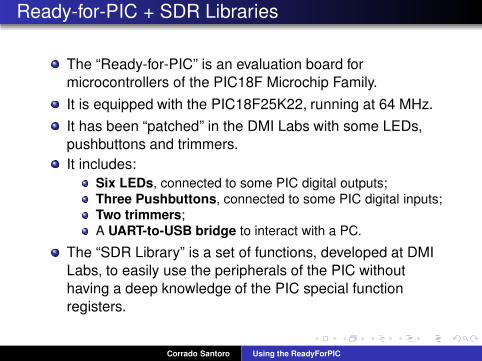
The “Ready-for-PIC” is an evaluation board for
microcontrollers of the PIC18F Microchip Family.
It is equipped with the PIC18F25K22, running at 64 MHz.
It has been “patched” in the DMI Labs with some LEDs,
pushbuttons and trimmers.
It includes:
Six LEDs, connected to some PIC digital outputs;
Three Pushbuttons, connected to some PIC digital inputs;Two trimmers;
A UART-to-USB bridge to interact with a PC.
The “SDR Library” is a set of functions, developed at DMI
Labs, to easily use the peripherals of the PIC without
having a deep knowledge of the PIC special function
registers.
Corrado Santoro Using the ReadyForPIC
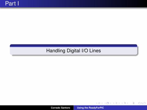
Part I
Handling Digital I/O Lines
Corrado Santoro Using the ReadyForPIC
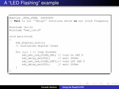
A “LED Flashing” example
✞#define _XTAL_FREQ 64000000
// Tell to our ‘‘delay’’ functions which is our clock frequency
#include <xc.h>
#include "sdr_lib.h"
void main(void)
{
sdr_digital_init();
// initialize digital lines
for (;;) { // loop forever
sdr_set_led_0(LED_ON); // turn on LED 0
sdr_delay_ms(200); // wait 200ms
sdr_set_led_0(LED_OFF);// turn off LED 0
sdr_delay_ms(200); // wait 200ms
}
}
✡✝ ✆
Corrado Santoro Using the ReadyForPIC
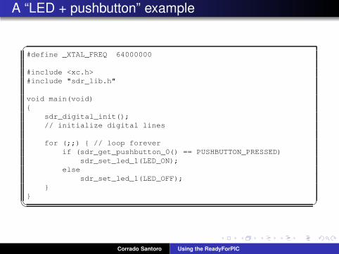
A “LED + pushbutton” example
✞#define _XTAL_FREQ 64000000
#include <xc.h>
#include "sdr_lib.h"
void main(void)
{
sdr_digital_init();
// initialize digital lines
for (;;) { // loop forever
if (sdr_get_pushbutton_0() == PUSHBUTTON_PRESSED)
sdr_set_led_1(LED_ON);
else
sdr_set_led_1(LED_OFF);
}
}
✡✝ ✆
Corrado Santoro Using the ReadyForPIC
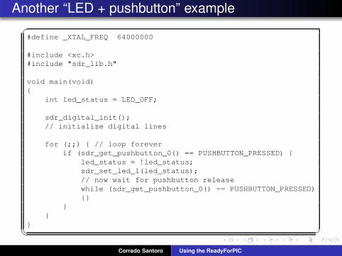
Another “LED + pushbutton” example
✞#define _XTAL_FREQ 64000000
#include <xc.h>
#include "sdr_lib.h"
void main(void)
{
int led_status = LED_OFF;
sdr_digital_init();
// initialize digital lines
for (;;) { // loop forever
if (sdr_get_pushbutton_0() == PUSHBUTTON_PRESSED) {
led_status = !led_status;
sdr_set_led_1(led_status);
// now wait for pushbutton release
while (sdr_get_pushbutton_0() == PUSHBUTTON_PRESSED)
{}
}
}
}
✡✝ ✆
Corrado Santoro Using the ReadyForPIC
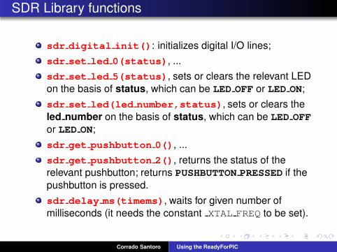
SDR Library functions
sdr digital init(): initializes digital I/O lines;
sdr set led 0(status), ...
sdr set led 5(status), sets or clears the relevant LED
on the basis of status, which can be LED OFF or LED ON;
sdr set led(led number,status), sets or clears the
led number on the basis of status, which can be LED OFF
or LED ON;
sdr get pushbutton 0(), ...
sdr get pushbutton 2(), returns the status of the
relevant pushbutton; returns PUSHBUTTON PRESSED if the
pushbutton is pressed.
sdr delay ms(timems), waits for given number of
milliseconds (it needs the constant XTAL FREQ to be set).
Corrado Santoro Using the ReadyForPIC
Part II
Using Timers
Corrado Santoro Using the ReadyForPIC
Timers
A timer is a circuit to let a software have the “knowledge of
flow of time”
It is a composed of:
A clock source; usually the system clock or an externalsignal;
A programmable frequency divisor, called prescaler, to
divide clock source frequency, if needed;Some SFRs which hold a 8-, 16- or 32-bit value that is
incremented in hardware using the clock source.Some SFRs which give some state information,
e.g overflow (zero crossing).
PIC18F family has 7 timers, called TIMER0, TIMER1, ...,
TIMER5, TIMER6
Each timer has different characteristics and may be used
together with other peripherals.
Corrado Santoro Using the ReadyForPIC
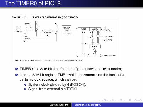
The TIMER0 of PIC18
TIMER0 is a 8/16 bit timer/counter (figure shows the 16bit mode);
It has a 8/16 bit register TMR0 which increments on the basis of a
certain clock source, which can be:
System clock divided by 4 (FOSC/4);
Signal from external pin T0CKI
Corrado Santoro Using the ReadyForPIC
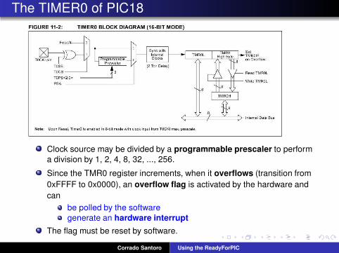
The TIMER0 of PIC18
Clock source may be divided by a programmable prescaler to perform
a division by 1, 2, 4, 8, 32, ..., 256.
Since the TMR0 register increments, when it overflows (transition from
0xFFFF to 0x0000), an overflow flag is activated by the hardware and
can
be polled by the software
generate an hardware interrupt
The flag must be reset by software.
Corrado Santoro Using the ReadyForPIC
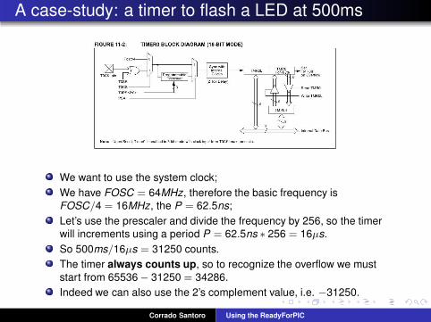
A case-study: a timer to flash a LED at 500ms
We want to use the system clock;
We have FOSC = 64MHz, therefore the basic frequency is
FOSC/4 = 16MHz, the P = 62.5ns;
Let’s use the prescaler and divide the frequency by 256, so the timer
will increments using a period P = 62.5ns ∗ 256 = 16µs.
So 500ms/16µs = 31250 counts.
The timer always counts up, so to recognize the overflow we must
start from 65536 − 31250 = 34286.
Indeed we can also use the 2’s complement value, i.e. −31250.
Corrado Santoro Using the ReadyForPIC
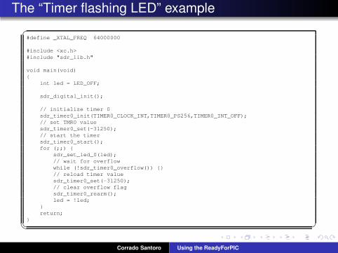
The “Timer flashing LED” example
✞#define _XTAL_FREQ 64000000
#include <xc.h>
#include "sdr_lib.h"
void main(void)
{
int led = LED_OFF;
sdr_digital_init();
// initialize timer 0
sdr_timer0_init(TIMER0_CLOCK_INT,TIMER0_PS256,TIMER0_INT_OFF);
// set TMR0 value
sdr_timer0_set(-31250);
// start the timer
sdr_timer0_start();
for (;;) {
sdr_set_led_0(led);
// wait for overflow
while (!sdr_timer0_overflow()) {}
// reload timer value
sdr_timer0_set(-31250);
// clear overflow flag
sdr_timer0_rearm();
led = !led;
}
return;
}
✡✝ ✆
Corrado Santoro Using the ReadyForPIC
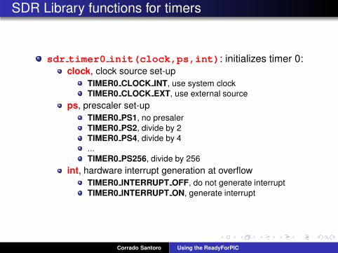
SDR Library functions for timers
sdr timer0 init(clock,ps,int): initializes timer 0:clock, clock source set-up
TIMER0 CLOCK INT, use system clock
TIMER0 CLOCK EXT, use external source
ps, prescaler set-up
TIMER0 PS1, no presaler
TIMER0 PS2, divide by 2
TIMER0 PS4, divide by 4
...
TIMER0 PS256, divide by 256
int, hardware interrupt generation at overflow
TIMER0 INTERRUPT OFF, do not generate interrupt
TIMER0 INTERRUPT ON, generate interrupt
Corrado Santoro Using the ReadyForPIC
SDR Library functions for timers
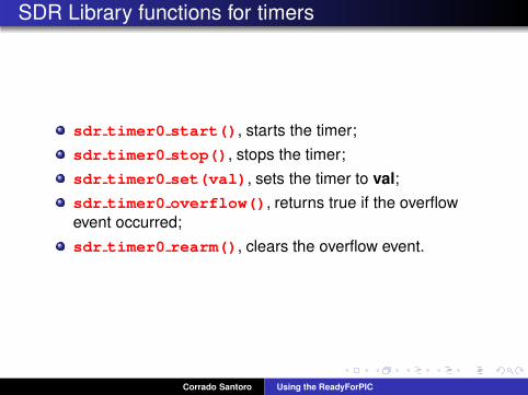
sdr timer0 start(), starts the timer;
sdr timer0 stop(), stops the timer;
sdr timer0 set(val), sets the timer to val;
sdr timer0 overflow(), returns true if the overflow
event occurred;
sdr timer0 rearm(), clears the overflow event.
Corrado Santoro Using the ReadyForPIC
Part III
Analog-to-Digital Converter
Corrado Santoro Using the ReadyForPIC
What is an ADC?
An ADC (Analog-to-Digital-Converter) is a circuit which gets an
analog voltage signal and provides (to software) a variable
proportional to the input signal.
An ADC is characterised by:
The range (in Volts) of the input signal (typical [0,5V ] or
[0,3.3V ]).
The resolution (in bits) of the converter.
Example:
Range = [0,5V ]
Resolution = 10 bits
results in range [0,210− 1] = [0,1023]
0V → 0 2.5V → 512 5V → 1023
Corrado Santoro Using the ReadyForPIC
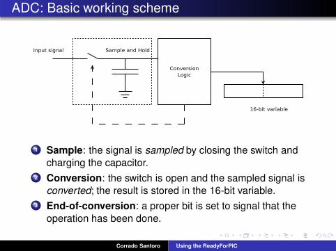
ADC: Basic working scheme
1 Sample: the signal is sampled by closing the switch and
charging the capacitor.
2 Conversion: the switch is open and the sampled signal is
converted; the result is stored in the 16-bit variable.
3 End-of-conversion: a proper bit is set to signal that the
operation has been done.
Corrado Santoro Using the ReadyForPIC
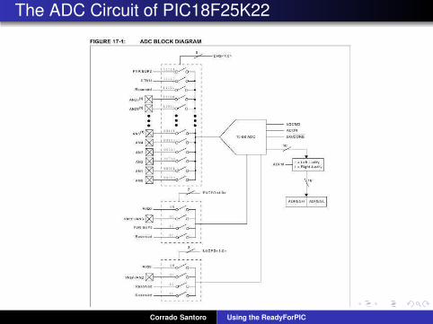
The ADC Circuit of PIC18F25K22
Corrado Santoro Using the ReadyForPIC
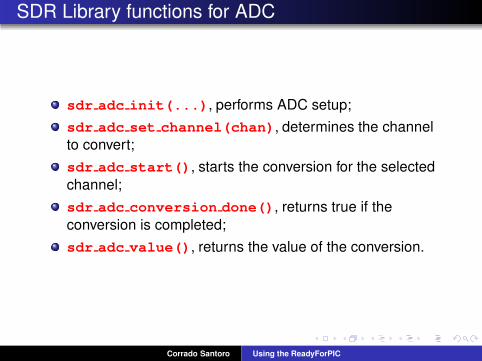
SDR Library functions for ADC
sdr adc init(...), performs ADC setup;
sdr adc set channel(chan), determines the channel
to convert;
sdr adc start(), starts the conversion for the selected
channel;
sdr adc conversion done(), returns true if the
conversion is completed;
sdr adc value(), returns the value of the conversion.
Corrado Santoro Using the ReadyForPIC
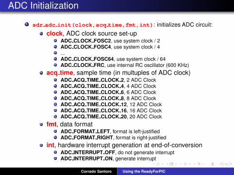
ADC Initialization
sdr adc init(clock,acq time,fmt,int): initializes ADC circuit:
clock, ADC clock source set-upADC CLOCK FOSC2, use system clock / 2ADC CLOCK FOSC4, use system clock / 4...ADC CLOCK FOSC64, use system clock / 64ADC CLOCK FRC, use internal RC oscillator (600 KHz)
acq time, sample time (in multuples of ADC clock)ADC ACQ TIME CLOCK 2, 2 ADC ClockADC ACQ TIME CLOCK 4, 4 ADC ClockADC ACQ TIME CLOCK 6, 6 ADC ClockADC ACQ TIME CLOCK 8, 8 ADC ClockADC ACQ TIME CLOCK 12, 12 ADC ClockADC ACQ TIME CLOCK 16, 16 ADC ClockADC ACQ TIME CLOCK 20, 20 ADC Clock
fmt, data formatADC FORMAT LEFT, format is left-justifiedADC FORMAT RIGHT, format is right-justified
int, hardware interrupt generation at end-of-conversionADC INTERRUPT OFF, do not generate interruptADC INTERRUPT ON, generate interrupt
Corrado Santoro Using the ReadyForPIC
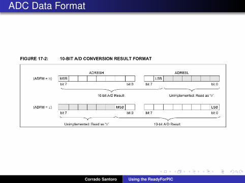
ADC Data Format
Corrado Santoro Using the ReadyForPIC
Part IV
Interrupt Handling
Corrado Santoro Using the ReadyForPIC
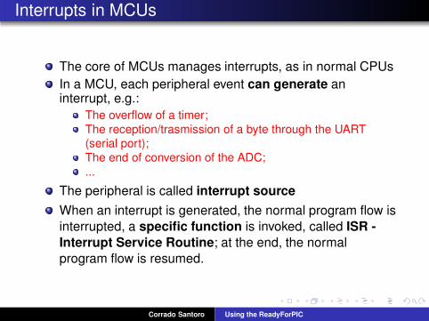
Interrupts in MCUs
The core of MCUs manages interrupts, as in normal CPUs
In a MCU, each peripheral event can generate aninterrupt, e.g.:
The overflow of a timer;
The reception/trasmission of a byte through the UART(serial port);
The end of conversion of the ADC;
...
The peripheral is called interrupt source
When an interrupt is generated, the normal program flow is
interrupted, a specific function is invoked, called ISR -
Interrupt Service Routine; at the end, the normal
program flow is resumed.
Corrado Santoro Using the ReadyForPIC
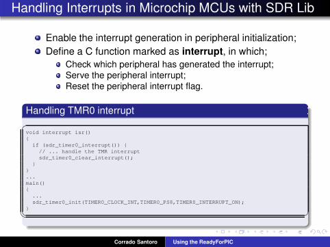
Handling Interrupts in Microchip MCUs with SDR Lib
Enable the interrupt generation in peripheral initialization;
Define a C function marked as interrupt, in which;
Check which peripheral has generated the interrupt;
Serve the peripheral interrupt;
Reset the peripheral interrupt flag.
Handling TMR0 interrupt
✞void interrupt isr()
{
if (sdr_timer0_interrupt()) {
// ... handle the TMR interrupt
sdr_timer0_clear_interrupt();
}
}
...
main()
{
...
sdr_timer0_init(TIMER0_CLOCK_INT,TIMER0_PS8,TIMER0_INTERRUPT_ON);
}
✡✝ ✆
Corrado Santoro Using the ReadyForPIC
Using the Ready-for-PIC Board with “SDR”
Libraries
Corrado Santoro
ARSLAB - Autonomous and Robotic Systems LaboratoryDipartimento di Matematica e Informatica - Universita di Catania, Italy
S.D.R. Course
Corrado Santoro Using the ReadyForPIC