Embed Size (px)
Citation preview
Analysis of Machine Elements using SolidWorks Simulation 2011
John R. Steffen, Ph.D., P.E.
SDC
www.SDCpublications.com
Schroff Development Corporation
PUBLICATIONS
Analysis of Machine Elements using SolidWorks Simulation
i
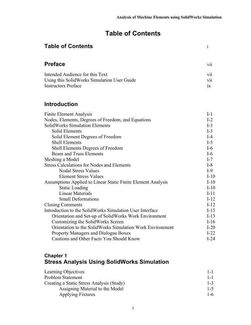
Table of Contents
Table of Contents i Preface vii
Intended Audience for this Text vii Using this SolidWorks Simulation User Guide vii Instructors Preface ix Introduction
Finite Element Analysis I-1 Nodes, Elements, Degrees of Freedom, and Equations I-2 SolidWorks Simulation Elements I-3 Solid Elements I-3 Solid Element Degrees of Freedom I-4 Shell Elements I-5 Shell Elements Degrees of Freedom I-6 Beam and Truss Elements I-6 Meshing a Model I-7 Stress Calculations for Nodes and Elements I-8 Nodal Stress Values I-9 Element Stress Values I-10 Assumptions Applied to Linear Static Finite Element Analysis I-10 Static Loading I-10 Linear Materials I-11 Small Deformations I-12 Closing Comments I-12 Introduction to the SolidWorks Simulation User Interface I-13 Orientation and Set-up of SolidWorks Work Environment I-13 Customizing the SolidWorks Screen I-16 Orientation to the SolidWorks Simulation Work Environment I-20 Property Managers and Dialogue Boxes I-22 Cautions and Other Facts You Should Know I-24 Chapter 1 Stress Analysis Using SolidWorks Simulation
Learning Objectives 1-1 Problem Statement 1-1 Creating a Static Stress Analysis (Study) 1-3 Assigning Material to the Model 1-5 Applying Fixtures 1-6
Analysis of Machine Elements using SolidWorks Simulation
ii
Applying External Loads 1-8 Meshing the Model 1-11 Running the Solution 1-13 Examination of Results 1-14 Default SolidWorks Simulation Graphical Results 1-14 Results Predicted by Classical Stress Equations 1-16 SolidWorks Simulation Results for Stress in Y-Direction 1-18 Using the Probe Tool 1-20 Customizing Graphs 1-27 Summary 1-30 Exercises 1-31 Chapter 2 Curved Beam Analysis
Learning Objectives 2-1 Problem Statement 2-1 Creating a Static Analysis (Study) 2-2 Assign Material Properties to the Model 2-5 Applying Fixtures 2-6 Applying External Load(s) 2-8 Inserting Split Lines 2-9 Applying Force to an Area Bounded by Split Lines 2-12 Meshing the Model 2-13 Solution 2-15 Examination of Results 2-16 Analysis of von Mises Stresses Within the Model 2-16 Verification of Results 2-19 Results Predicted by Classical Stress Equations 2-19 Comparison with Finite Element Results 2-21 Assessing Safety Factor 2-25 Alternate Stress Display Option 2-31 Determining Reaction Forces 2-32 Logging Out of the Current Analysis 2-33 Exercises 2-34 Chapter 3 Stress Concentration Analysis
Learning Objectives 3-1 Problem Statement 3-1 Create a Static Analysis (Study) 3-2 Defeaturing the Model 3-3 Assign Material Properties to the Model 3-4 Apply Fixtures and External Loads 3-4
Table of Contents
iii
Meshing the Model 3-6 Solution 3-7 Examination of Results 3-7 Stress Plots 3-7 Creating a “Copy” of a Plot 3-11 Displacement Plot 3-13 Creating New Studies 3-15 Basic Parts of the Graphical User Interface 3-15 Study Using High Quality Elements and COARSE Mesh Size 3-17 Method 1 – Item by Item Copying 3-17 Study Using High Quality Elements and DEFAULT Mesh Size 3-20 Method 2 – Copying Multiple Items Simultaneously 3-20 Study Using High Quality Elements and FINE Mesh Size 3-22 Method 3 – Duplicating an Entire Study 3-22 Study Using High Quality Elements and MESH CONTROL 3-25 Summary 3-30 Results Analysis 3-30 Create Multiple Viewports 3-31 What Can Be Learned from this Example? 3-33 Other Uses of the Copy Feature 3-33 Comparison of Classical and FEA Results 3-37 Exercises 3-39 Chapter 4 Thin and Thick Wall Pressure Vessels
Learning Objectives 4-1 Thin-Wall Pressure Vessel (Using Shell Elements) 4-1 Problem Statement 4-1 Understanding System Default Settings 4-4 Creating a Static Analysis Using Shell Elements 4-10 Converting a Solid Model to a Shell Model 4-11 Open a New Simulation Study 4-15 Assign Material Properties 4-15 Define Shell Thickness 4-15 Assign Fixtures and External Loads 4-16 Symmetry Restraints Applied 4-16 Pressure Load Applied 4-20 Mesh the Model 4-21 Solution 4-23 Results Analysis 4-23
Analysis of Machine Elements using SolidWorks Simulation
iv
Thick Wall Pressure Vessel 4-29 Problem Statement 4-29 Defining the Study 4-30 Assign Material Properties 4-31 Define Fixtures and External Loads 4-31 Create a Duplicate Study 4-34 Mesh the Model – Default Size Standard Mesh 4-34 Mesh the Model – Fine Size Standard Mesh 4-35 Solution 4-37 Results Analysis 4-37 Displacement Analysis 4-37 von Mises Stress Analysis 4-39 Tangential Stress Analysis 4-39 Adjusting Stress Magnitude Display Parameters 4-42 Using Section Clipping to Observe Stress Results 4-45 Exercises 4-49 Chapter 5 Interference Fit Analysis
Learning Objectives 5-1 Problem Statement 5-1 Interference Check 5-2 Create a Static Analysis (Study) 5-3 Assign Material Properties to the Model 5-4 Defeature and Simplify the Model 5-5 Apply Fixtures 5-6 Unsuppress Part of the Model to Use Symmetry 5-6 Define Symmetry Restraints (Fixtures) 5-7 Apply Fixtures to Eliminate Rigid Body Motion 5-8 Use Contact Sets to Define a Shrink Fit 5-10 Mesh the Model and Run the Solution 5-13 Examination of Results 5-14 Default Stress Plot 5-14 Stress Plots in a Cylindrical Coordinate System 5-17 Circumferential (Tangential or Hoop) Stress 5-17 Radial Stress 5-20 Verification of Results 5-22 Stress Predicted by Classical Interference Fit Equations 5-22 Stress Predicted by Finite Element Analysis 5-23 Radial Stress Comparison 5-23 Circumferential Stress Comparison 5-25 Quantifying Radial Displacements 5-26 Generating a Report 5-29 Exercises 5-32
Table of Contents
v
Chapter 6 Contact Analysis in a Trunion Mount
Learning Objectives 6-1 Problem Statement 6-1 Preparing the Model for Analysis 6-2 Add Reference Planes 6-3 Insert Split Lines 6-4 Create the Assembly Model 6-5 Cut Model on Symmetry Plane 6-9 Create a Finite Element Analysis (Study) 6-12 Assign Material Properties 6-13 Assign Fixtures and External Loads 6-13 Symmetry and Immovable Restraints 6-13 Connections Define Contact Conditions 6-14 Apply a Directional Load 6-16 Meshing the Model and Running the Solution 6-19 Results Analysis 6-19 Von Mises Stress 6-19 Iso Clipping 6-20 Animating Stress Results 6-22 Displacement Results 6-23 Contact Pressure/Stress 6-24 Exercises 6-26 Chapter 7 Bolted Joint Analysis
Learning Objectives 7-1 Problem Statement 7-1 Create a Static Analysis (Study) 7-2 Assign Material Properties to the Model 7-2 Apply External Loads and Fixtures 7-3 Traditional Loads and Fixtures 7-3 Define Bolted Joint Restraints 7-4 Define Local Contact Conditions 7-11 Mesh the Model and Run Solution 7-13 Results Analysis for the Downward External Load 7-16 von Mises Stress 7-16 Bolt Forces (for Downward Load) 7-18 Define a New Study with the Applied Force Acting Upward 7-19 Results Analysis for the Upward External Load 7-20 von Mises Stress 7-20 Bolt Forces (for Upward Load) 7-23 Bolt Clamping Pressure 7-26 Summary 7-30 Exercises 7-31
Analysis of Machine Elements using SolidWorks Simulation
vi
Chapter 8 Design Optimization
Learning Objectives 8-1 Problem Statement 8-1 Complete and Run the Initial Study 8-2 Generating an Optimization Design Study 8-6 Understanding Optimization Design Terminology 8-7 Selecting and Specifying Design Parameters (Variables) 8-8 Define Constraints and their Sensors 8-13 Define the Stress Constraint and Sensor 8-14 Define the Displacement Constraint and Sensor 8-14 Define a Goal and its Sensor 8-16 Overview of Results 8-17 General Observations 8-18 Local Trend Graphs 8-19 Local Trend Graph of the Design Goal versus a Design Variable 8-19 Local Trend Graph of a Constraint versus a Design Variable 8-21 Closing Observations 8-22 Exercises 8-24 APPENDIX A
Organizing Assignments using MS Word® A-1 APPENDIX B
Alternative Method to Alter Graphics Area Background color B-1 INDEX Index-1