Embed Size (px)
Citation preview
USING SYNCHROTRON IMAGING TECHNIQUES
TO SOLVE PROBLEMS IN NEUROSURGERY
A Thesis Submitted
to the College of Graduate Studies and Research
in Partial Fulfillment of the Requirements
for the Degree of Doctor of Philosophy
in the Department of Anatomy and Cell Biology
University of Saskatchewan
Saskatoon
By
Michael EB Kelly, MD, FRCSC
© Copyright Michael EB Kelly, February 2010. All rights reserved.
i
PERMISSION TO USE
In presenting this thesis in partial fulfillment of the requirements for a Postgraduate
degree from the University of Saskatchewan, I agree that the Libraries of this University may
make it freely available for inspection. I further agree that permission for copying of this thesis
in any manner, in whole or in part, for scholarly purposes may be granted by the professor or
professors who supervised my thesis work or, in their absence, by the Head of the Department or
the Dean of the College in which my thesis work was done. It is understood that any copying or
publication or use of this thesis or parts thereof for financial gain shall not be allowed without
my written permission. It is also understood that due recognition shall be given to me and to the
University of Saskatchewan in any scholarly use which may be made of any material in my
thesis.
Requests for permission to copy or to make other use of material in this thesis in whole or
part should be addressed to:
LD Chapman, PhD, Department of Anatomy and Cell Biology,
University of Saskatchewan,
Saskatoon, Saskatchewan , S7N 5E5
EXAMINING AND ADVISORY COMMITTEE
Dean/Associate Dean, Dean's Designate, Chair
College of Graduate Studies and Research
Dr H Nichol Chair of Advisory Committee, Department of
Anatomy and Cell Biology
Dr BHJ Juurlink Co-supervisor, Department of Department of
Anatomy and Cell Biology
Dr LD Chapman Co-supervisor, Department of Department of
Anatomy and Cell Biology
Dr D Fourney College of Medicine
Dr M Mayer College of Veterinary Medicine
Dr P Paterson College of Pharmacy
Dr M West (External Examiner) Department of Neurosurgery, University of
Manitoba
ii
ABSTRACT
Objective: The purpose of the research presented in this thesis is to explore new
biomedical applications of synchrotron imaging in the field of neurosurgery.
Methods: Four different studies were performed, all using advanced biomedical
synchrotron imaging techniques. In the first two experiments, diffraction enhanced imaging
(DEI) and analyzer based imaging (ABI) were utilized to study the anatomy of the rat spine and
a novel rat model of spinal fusion. In a third experiment, K-edge digital subtraction angiography
(KEDSA) was used to study the cerebral vasculature in a rabbit model. In a fourth experiment,
rapid scanning X-ray fluorescence spectroscopy (RS-XRF) was used to study stem cell migration
in a rat stroke model.
Results: DEI had superior visualization of ligamentous and boney anatomy in a rat
model. Analyzer based imaging was able to visualize physiologic amounts of bone graft material
and progressive incorporation into the spine. Intravenous KEDSA showed excellent visualization
of the cerebral vasculature in a rabbit model. Finally, RS-XRF was used to track iron labeled
stem cells implanted in a rat stroke model. The technique was able to visualize the iron that
represented the stem cell migration. This was correlated with histology and magnetic resonance
imaging information.
Conclusions: 1) Diffraction enhanced imaging has excellent contrast for the study of
boney and ligamentous anatomy. 2) Analyzer based imaging is an excellent tool to study animal
models of boney fusion. 3) Intravenous KEDSA is able to clearly visualize the arterial
vasculature in a rabbit model. 4) RS-XRF can be used to study the migration patterns of
implanted iron labeled stem cells.
iii
ACKNOWLEDGEMENTS
I would like to thank the many people who assisted me during my PhD research.
Particular credit should go to Elisabeth Shultke, MD, PhD; Dean Chapman, PhD; Helen Nichol,
PhD; Bernhard Juurlink, PhD; and Cole Beavis, MD. Without their assistance with the
experiments, I could not have completed this research.
Drs. Juurlink, Griebel, Schultke, and Kamencic introduced me to animal surgery and
basic science research. Drs. Steinberg and Guzman at Stanford must be acknowledged. Dr.
David Fiorella, MD, PhD continues to be my inspiration to publish and perform both basic
science and clinical research.
I would also like to thank the Departments of Surgery and Anatomy and Cell Biology for
their financial and other support, as well as the American Association of Neurological Surgeons
for financial support provided through the Neurosurgery Research and Education Foundation
(NREF) DePuy Research Fellowship.
Finally, I would like to thank my wife Kyla for supporting me through my entire career.
Her unwavering support is what allowed me to achieve my goals.
DEDICATION
This thesis is dedicated to my sons, Andrew and Carter, and my wife Kyla.

iv
TABLE OF CONTENTS
PERMISSION TO USE i
EXAMINING AND ADVISORY COMMITTEE i
ABSTRACT ii
ACKNOWLEDGEMENTS iii
DEDICATION iii
TABLE OF CONTENTS iv
LIST OF TABLES vii
LIST OF FIGURES vii
LIST OF ABBREVIATIONS ix
CHAPTER 1. INTRODUCTION AND RESEARCH QUESTIONS 1
1.1. Rationale for experiments 1
1.2. Introduction 2
1.2.1. Introduction to synchrotron radiation 2
1.2.2. Diffraction enhanced imaging 4
1.2.3. K-edge digital subtraction angiography 8
1.2.4. Rapid scanning X-ray fluorescence spectroscopy 11
1.2.5. Synchrotron-based rapid scanning X-ray fluorescence spectroscopy 12
1.3. References 14
CHAPTER 2. DIFFRACTION ENHANCED IMAGING OF THE RAT SPINE 18
2.1. Introduction 18
2.2. Materials and methods 18
2.2.1. Technique of DEI 20
2.3. Results 21
2.4. Discussion 28
2.5. Conclusion 30
2.6. Acknowledgements 30
2.7. References 30
CHAPTER 3. ANALYZER BASED IMAGING OF SPINAL FUSION IN AN ANIMAL
MODEL 32
v
3.1. Introduction 32
3.2. Materials and methods 33
3.2.1 Animal model 33
3.2.2 Surgical procedure 34
3.2.3 Assessment of fusion by manual testing 35
3.2.4 Technique of analyzer based imaging 35
3.2.5 Technique of absorption radiography 36
3.2.6 Assessment of fusion 36
3.3. Results 37
3.3.1. Manual testing of fusion 37
3.3.2. Absorption radiography 37
3.3.3. Analyzer based imaging 37
3.4. Discussion 42
3.5. Conclusions 44
3.6. Acknowledgements 44
3.7. References 44
CHAPTER 4. SYNCHROTRON-BASED INTRAVENOUS CEREBRAL ANGIOGRAPHY IN
A SMALL ANIMAL MODEL 47
4.1. Introduction 47
4.2. Materials and methods 48
4.2.1 Conventional intraarterial and intravenous cerebral angiography 49
4.2.2 K-edge digital subtraction angiography 49
4.3. Results 52
4.3.1. Conventional angiography 52
4.3.2. K-edge digital subtraction angiography 53
4.4. Discussion 58
4.5. Conclusions 61
4.6. Acknowledgements 61
4.7. References 62

vi
CHAPTER 5. RAPIC SCANNING X-RAY FLUORESCENCE IMAGING OF
MAGNETICALLY LABELED STEM CELLS IN A RAT STROKE MODEL, A PILOT
STUDY 64
5.1. Introduction 64
5.2. Methods 65
5.2.1. Stem cell preparation 65
5.2.2. dMCAO method 66
5.2.3. Stereotactic stem cell transplantation, histology and imaging 66
5.3. Results 66
5.3.1. MRI 66
5.3.2. RS-XRF 67
5.4. Discussion 67
5.4.1. Detection of decreased SPIO concentrations with cell division and migration 68
5.4.2. Quantification of graft size 68
5.4.3. Reliance on SPIO for cell detection using MRI 69
5.4.4. Limitations of current study 69
5.5. Conclusion 69
5.6. Acknowledgements 70
5.7. References 70
CHAPTER 6. DISCUSSION 73
6.1. Overview 73
6.2. Diffraction enhanced imaging of the spine 74
6.3. Analyzer based imaging of spinal fusion in an animal model 74
6.4. K-edge digital subtraction angiography 75
6.5. Rapid scanning X-ray fluorescence 76
6.6. Summary 77
CHAPTER 7. CONCLUSIONS 78
CHAPTER 8. IMPACT 79
APPENDIX. SIMULTANEOUS ACHIEVEMENTS DURING PHD 80
A.1. Completion of neurosurgery residency and certification by the Royal College of
Physicians and Surgeons in Neurosurgery 80

vii
A.2. Completion of three year fellowship training in cerebrovascular and endovascular
neurosurgery 80
A.3. Other publications and presentations 81

viii
LIST OF TABLES
Table 3.1. Animal groups used in study, n=21 34
Table 3.2. Results of ABI of spine muscle blocks to assess fusion 38

ix
LIST OF FIGURES
Figure 1.1. DEI setup at the National Synchrotron Light Source, beamline X15A. (from Kelly et
al., 2006) 5
Figure 1.2. Analyzer rocking curve at 18 keV, illustrating low and high angle sides and
associated refraction images. The apparent absorption image occurs at the peak of the
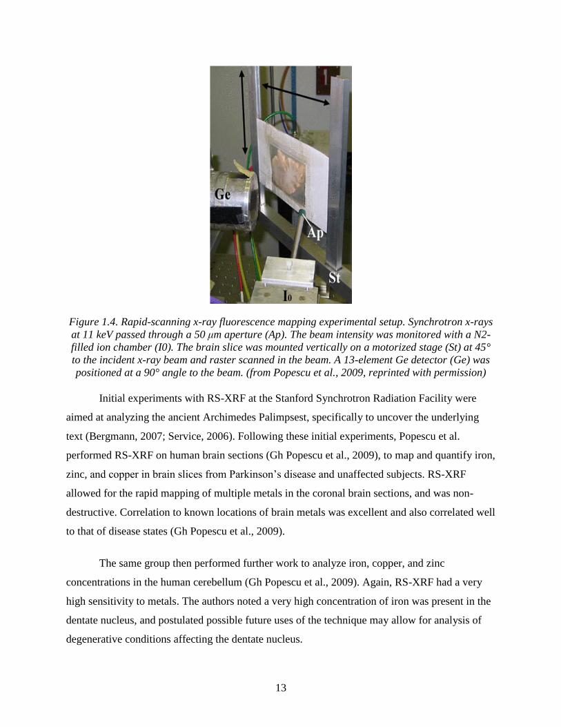
rocking curve. (from Chapman et al., 1997) 6 Figure 1.3. Photon energy of X-ray and mass attenuation coefficient. (from Ito et al., 1998) 9 Figure 1.4. Rapid-scanning x-ray fluorescence mapping experimental setup. Synchrotron x-rays
at 11 keV passed through a 50 μm aperture (Ap). The beam intensity was monitored with
a N2-filled ion chamber (I0). The brain slice was mounted vertically on a motorized stage
(St) at 45° to the incident x-ray beam and raster scanned in the beam. A 13-element Ge
detector (Ge) was positioned at a 90° angle to the beam. (from Popescu et al., 2009) 13
Figure 2.1. DEI setup at the National Synchrotron Light Source, Brookhaven National
Laboratory that was used for imaging (a). 20
Figure 2.2. Standard absorption radiography (a) and DEI (b) of a standard X-ray phantom
showing improved contrast with DEI. 22
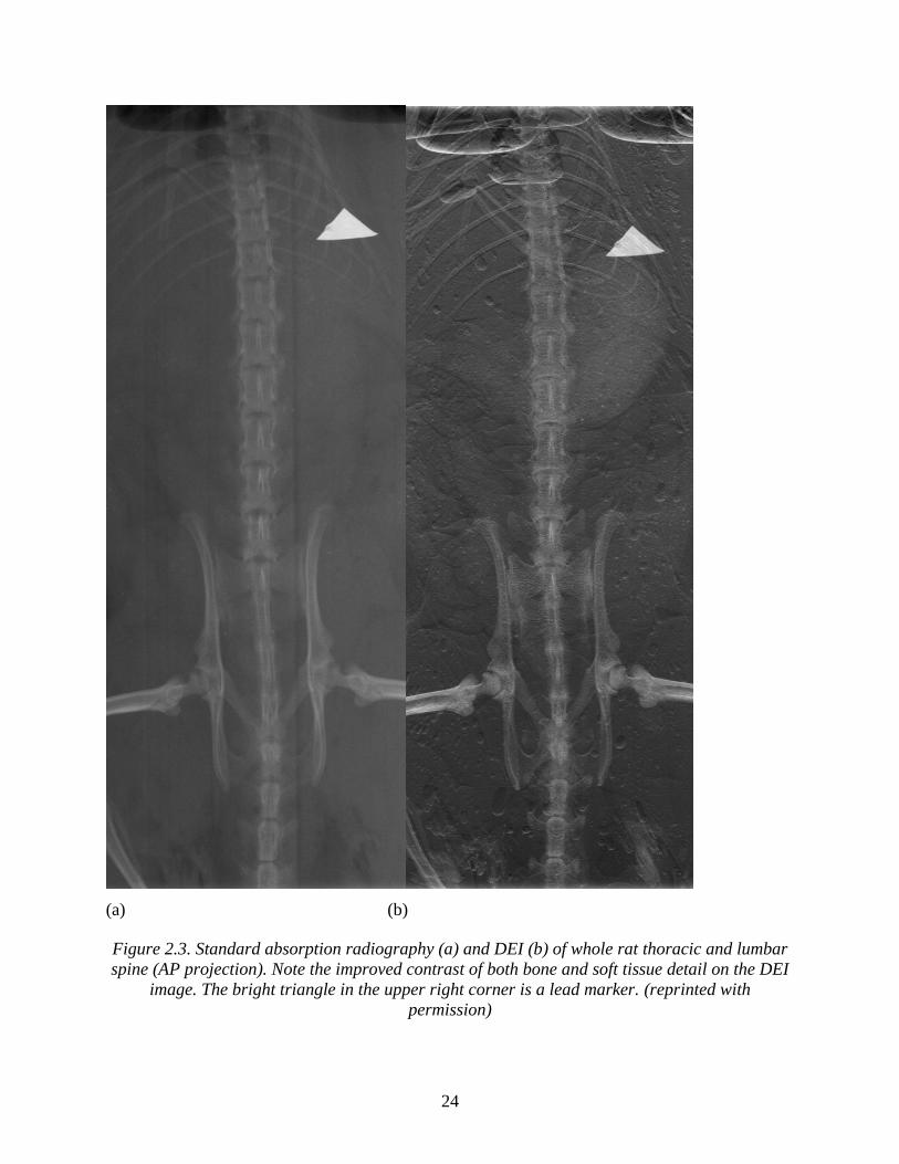
Figure 2.3. Standard absorption radiography (a) and DEI (b) of whole rat thoracic and lumbar
spine (AP projection). Note the improved contrast of both bone and soft tissue detail on
the DEI image. The bright triangle in the upper right corner is a lead marker. 24
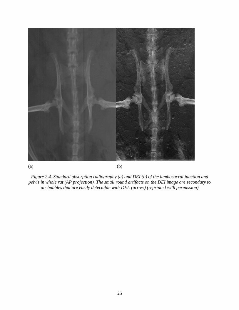
Figure 2.4. Standard absorption radiography (a) and DEI (b) of the lumbosacral junction and
pelvis in whole rat (AP projection). The small round artifacts on the DEI image are
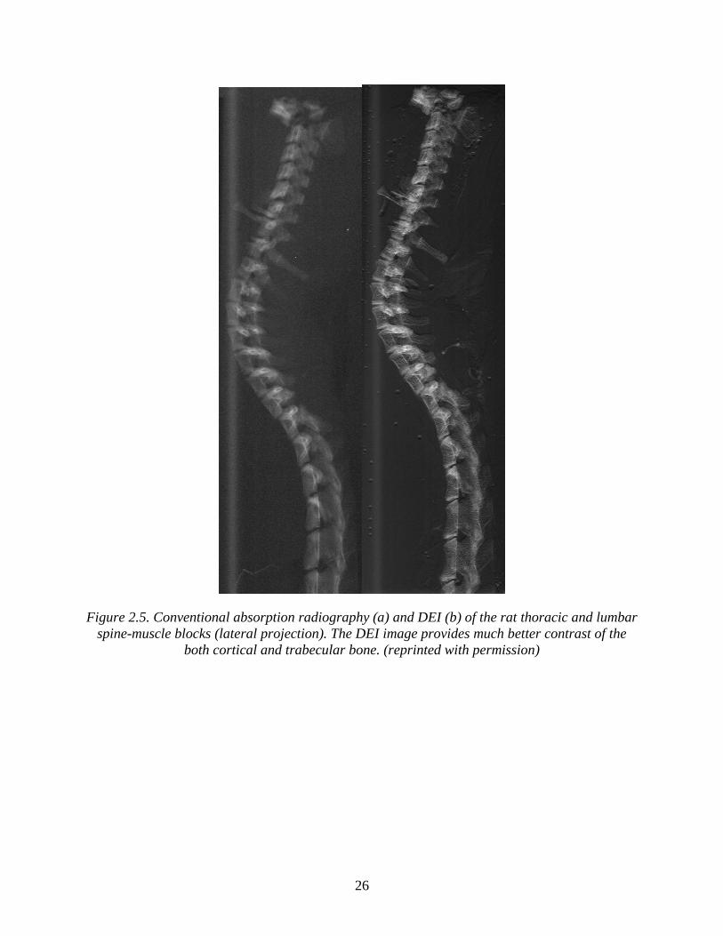
secondary to air bubbles that are easily detectable with DEI. (arrow) 25 Figure 2.5. Conventional absorption radiography (a) and DEI (b) of the rat thoracic and lumbar
spine-muscle blocks (lateral projection). The DEI image provides much better contrast of
the both cortical and trabecular bone. 26
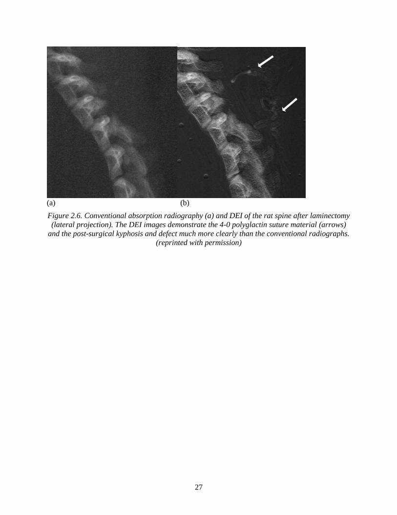
Figure 2.6. Conventional absorption radiography (a) and DEI of the rat spine after laminectomy
(lateral projection). The DEI images demonstrate the 4-0 polyglactin suture material
(arrows) and the post-surgical kyphosis and defect much more clearly than the
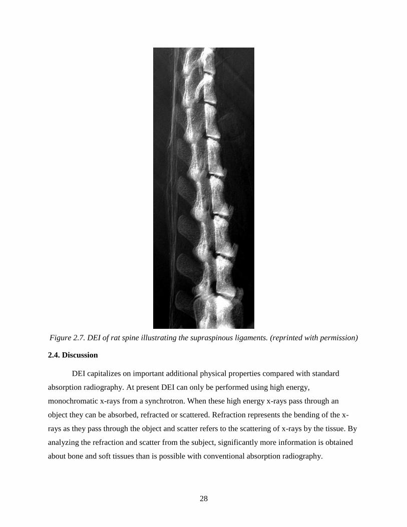
conventional radiographs. 27 Figure 2.7. DEI of rat spine illustrating the supraspinous ligaments. 28
Figure 3.1. Group 1 subject (control – 6 weeks post-procedure). a) AP absorption radiography of
the lumbosacral spine and pelvis provides gross visualization of the spinal anatomy. b)
AP analyzer based imaging shows significantly improved detail of the spinal anatomy
compared to the radiograph. The trabeculation pattern of all of the osseous structures can
be visualized. The edges of the osseous structures, particularly the lateral aspects of the
transverse processes of the lumbar vertebrae are very well demonstrated. 38
Figure 3.2. Group 3 subject (iliac crest bone grafting and fusion – 2 weeks post-procedure). a)
AP absorption radiograph shows no visible bone graft material (arrow depicts the
expected location of some of the bone graft material which was applied along the lateral
aspect of the vertebral column). Because the graft material cannot even be visualized, the
absorption image is insufficient to evaluate for graft incorporation in this small animal
model. b) AP analyzer based imaging (ABI) shows the bone graft material distributed
along the lateral aspects of the vertebral column. An arrow depicts one of the
unincorporated graft fragments along the right lateral aspect of the vertebral column. The
clear circumferential demarcation of a distinct cortical surface around the periphery of the
x
fragment indicates that it has not yet become fused. c) Magnified AP ABI image as
depicted in (b). d) Magnified AP ABI images as depicted in (c) with dotted outlines
demarcating several of the individual unincorporated graft fragments. These fragments
which are demonstrated that have clear resolution on ABI images are not even visualized
on the AP absorption radiograph. 39 Figure 3.3. Group 4 subject (iliac crest bone grafting and fusion with instrumentation – 6 weeks
post-procedure). AP absorption radiography does not show a clear fusion mass (a). A
small amount of heterotopic bone formation is depicted just superior to the right iliac
crest (a, arrowhead). A tiny amount of fusion material is vaguely seen along the left
lateral aspect of the vertebral column (a, arrow). ABI (b) shows clear evidence of a well
incorporated fusion mass along the right lateral aspect of the vertebral column (arrow).
Extensive heterotopic bone formation is evident along the superior aspect of the iliac
crest and elsewhere (see below). The same ABI image is shown again with demarcations
(c) indicating the location of heterotopic bone along the right iliopsoas musculature
(hatched lines), along the lateral aspects of both iliac wings (dotted ovals), above the left
iliac crest (dotted triangle), and over the right iliac crest (freeform dotted outline). The
dotted rectangle depicts the solid fusion mass which has been incorporated along the right
lateral aspect of the vertebral column. 40 Figure 3.4. Group 4 subjects (iliac crest bone grafting and fusion with instrumentation).
Magnified AP radiograph (a) and ABI (b) at 2 weeks post-procedure. The AP absorption
radiograph (a) demonstrates amorphous density distributed along the lateral aspects of the
vertebral columns corresponding to the location of bone graft material. Due to the lack of
contrast, no comment can be made as to the incorporation of the graft. ABI (b) of the
same specimen demonstrates well circumscribed fragments of bone graft material
distributed along the lateral aspects of the vertebral column, indicating that the graft
material has not yet been incorporated as a fusion mass. At 4 weeks post-procedure, AP
absorption radiograph (c) shows amorphous density material along the lateral aspects of
the vertebral column. The material appears less dense than on the 2-week AP radiograph,
however, it is difficult to assess the level of incorporation given the lack of contrast. ABI
(d) of the same specimen shows interval evolution of the fusion mass with incorporation
of a thick mantle of bone graft along the lateral aspects of the vertebral column. The
intervertebral disc space has become obscured. At 6 weeks post-procedure, the graft
material is again, inconspicuous on the AP radiograph (e) making any assessment of the
level of incorporation difficult. ABI of the same specimen (f) demonstrates a thick,
continuous mantle of graft material along the lateral aspects of the vertebral column,
consistent with complete incorporation of the bone graft material which now has created
a solid fusion mass. 41
Figure 4.1. Digital subtraction angiogram of the Circle of Willis in antero-posterior projection
after intra-arterial injection of iodinated contrast agent into the left carotid artery,
acquired with conventional X-ray equipment (adult rabbit). 52
Figure 4.2. Digital subtraction image in antero-posterior projection after intravenous injection of
iodinated contrast agent, acquired with conventional X-ray equipment (adult rabbit). 53 Figure 4.3. Image of intracerebral arteries acquired in radiography mode with the germanium
detector in antero-posterior projection, using synchrotron K-edge digital subtraction
angiography. (a): early filling phase (b): late filling phase. 54
xi
Figure 4.4. Images acquired below (a) and above (b) the K-edge of iodine, both without easily
discernible contrast in the cerebral arteries. The subtracted image (c), however, shows
very good contrast in the cerebral arteries. 55 Figure 4.5. Images of the cerebral arteries acquired with the FRELON camera in radiography
mode; pixel size 47 x 47 m,; Iomeprol® 1 mL /sec for 3 seconds. Image 1 was acquired
with 10 seconds delay after injection (a). Early (b) and late (c) arterial filling phases. End
of arterial phase (d). 56 Figure 4.6. Image series acquired with Ge detector in tomography mode; helical CT scan; pixel
size 350 x 350 m; Iomeprol® 1 mL /sec for 3 seconds (total volume of 3 mL). Images
were acquired 3 sec (a), 4 sec (b), 5 sec (c) and 6 sec (d) after injection. 57 Figure 4.7. Comparison of images acquired in tomography mode with the FRELON camera,
using synchrotron-based KEDSA. Pixel size was 47 x 47 m. (a) Reconstructed tissue
image, no contrast injection. (b) K-edge subtraction image with 5 mL / kg Iomeprol® (0.5
mL / sec over 30 seconds). 58 Figure 5.1. A. ex vivo whole brain Coronal T2 weighted spin echo MRI performed 5 weeks after
implantation of SPIO labeled hCNS-SCns in a stroked rat brain. The site of implantation
is denoted by the arrowhead. The arrows depict the SPIO that represents the migration of
the stem cells to the site of prior infarction. B. RS-XFS performed in the same animal
after sacrifice and coronal sectioning. The arrowheads denote the detection of iron. This
is noted to correlate to the same location as seen in the MRI in A. Although the image is
more pixilated better localization of the SPIO is observed. 67

xii
LIST OF ABBREVIATIONS
ABI analyzer based imaging
CHRP Canadian Health Research Program
CIHR Canadian Institutes of Health Research
CNS central nervous system
CT computerized tomography
CTA computerized tomography angiography
DEI diffraction enhanced imaging
dMCAO distal middle cerebral artery model
DSA digital subtraction cerebral angiography
Ek the absorption k-edge
ESRF European Synchrotron Radiation Facility
KEDSA K-edge digital subtraction angiography
meV millielectron volt
mGy milli-Gray
MRA magnetic resonance angiography
MRI magnetic resonance imaging
NREF Neurosurgery Research and Education Fellowship
NSERC Natural Sciences and Engineering Research Council of Canada
RS-XRF Rapid scanning X-ray fluorescence
SPIO superparamagnetic iron oxide
SYRMEP Synchrotron Radiation for Medical Physics
THRUST Training in Health Research Using Synchrotron Techniques
XRF X-ray fluorescence
1
CHAPTER 1.
INTRODUCTION AND RESEARCH QUESTIONS
1.1. Rationale for experiments
This PhD research was undertaken with the specific goal of incorporating various
synchrotron-based biomedical imaging techniques to explore problems in the field of
neurological surgery. Although the topics presented in this thesis may appear diverse, they are
related through this shared goal. The research presented in this thesis was developed alongside
my neurosurgical training, and this influence resulted in the following thesis as well other related
research.
Synchrotron physics is certainly not considered to be within the natural realm of a
neurosurgeon. However, when I began to explore the field of synchrotron radiation I was both
fascinated with the field and intrigued by the potential application of these techniques to solve
problems in neurosurgery. The PhD research presented here represents this evolution, wherein I
devised successive experiments that originated from knowledge and experience obtained from
prior experiments and the current stage of my neurosurgery training. Due to dual influences, the
research is very novel to both neurosurgical and synchrotron fields.
The experiments began with an attempt to use diffraction enhanced imaging to study
spinal cord injury. These experiments were performed at the National Synchrotron Radiation
Facility at the Brookhaven National Laboratory. Unfortunately, the experiment as intended failed
as we could not visualize the rat spinal cord. However, excellent visualization of the boney and
ligamentous spinal anatomy was observed. This led to the first publication related to this thesis
―Diffraction enhanced imaging of the rat spine‖ (Chapter 2). During this time in my
neurosurgery training I was interested in spinal surgery. In a review of the literature on spinal
2
fusion models, I noted current techniques were unable to identify small amounts of bone graft
placed in rat spine fusion models. I therefore developed a novel animal model of spinal fusion
and imaged it using diffraction enhanced imaging. This represents the second experiment
presented in this thesis (Chapter 3).
After this period in my neurosurgical training, my attention turned from spinal disorders
to cerebrovascular disorders. I became interested in how I could apply K-edge digital subtraction
angiography to neurosurgery. The ensuing experiments performed at the European Synchrotron
Radiation Facility originated from this question. This research constitutes the section of this
thesis entitled ―Synchrotron-based cerebral angiography in a small animal model‖ (Chapter 4).
The final experiments involved rapid scanning X-ray fluorescence imaging. During my
cerebrovascular surgery fellowship training at Stanford University, I was exposed to various
stem cell models for stroke therapy. Simultaneously, I participated in an experiment with Helen
Nichol, PhD, looking at metal mapping in human brains at the Stanford Synchrotron Radiation
Facility. At Stanford, I recognized the ability of rapid scanning X-ray fluorescence imaging to
track magnetically-labeled stem cells. This became the final experiment of this thesis (Chapter 5)
and is now the major focus of my ongoing research.
I am honoured to present the research in this thesis for consideration towards the degree
of PhD from the University of Saskatchewan. I have also included an appendix that outlines
other simultaneous accomplishments during my PhD studies.
1.2. Introduction
1.2.1. Introduction to synchrotron radiation
Synchrotron radiation results when charged particles traveling at near relativistic speeds
encounter external magnetic fields that force the particles into a polygonal path. Synchrotron
radiation (70 millielectron volt; meV) was first produced in 1947 by General Electric. Since that
time, many synchrotrons have been built around the world and have allowed for significant
discoveries in the fields of physics, medicine, and engineering.

3
Synchrotron radiation sources provide very high intensity, tunable, and multiple beams of
photons over a very broad spectrum of energy (Lewis, 1997). Highly monochromatic beams of
light can be selected, with energy ranging from infrared to hard X-rays. These characteristics
have significant benefits over conventional X-ray sources.
Synchrotron radiation originates from an electron gun. A cathode produces free electrons
that are placed into a stream by an electric field. The linear accelerator then employs microwaves
and radiowaves to accelerate the electrons to near the speed of light. The electrons are cut into
packets in the linear accelerator. The linear accelerator feeds the electrons into a booster ring.
Magnetic fields force the electrons into a circular polygonal orbit around the ring. Further speed
is added to the electrons by radio waves. The electrons are then moved to the storage ring.
The storage ring allows for a continuous quasi orbit of charged particles that can last for
many hours (Lewis, 1997; Suortti and Thomlinson, 2003). These charged particles can be either
electrons or positrons, and their orbit is maintained by repeatedly applying radiofrequency fields
to cause them to further accelerate. The storage ring is able to accelerate electrons to near
relativistic speeds. The basic components of a synchrotron ring are a high-vacuum chambers in
which the beam circulates. The ring is composed of multiple straight sections connected by
multiple bends that hold bending magnets (Lewis, 1997). When an electron circulating in the
vacuum is subjected to a magnetic field at the bend, it emits a fan of radiation. At these bending
points, the light can be utilized for experimental procedures.
The radiation released by the electrons is diploic in nature; that is, a figure eight shape
when at rest. When the electron is accelerated to near relativistic speeds, the Lorentz
transformation occurs and the distribution of the energy becomes very peaked in the forward
direction (Lewis, 1997). This allows for a highly collimated beam of radiation to be emitted in
the plane of the ring. The radio frequency fields applied to the electrons in the ring creates
packets of electrons that circulate in the ring.
The use of insertion devices allows for further manipulation of the radiation as it
circulates around the ring. Devices such as wigglers, undulators, and wavelength shifters are
used to precisely focus the electron beam and increase photon flux. As summarized by Lewis
4
(1997), synchrotron radiation includes properties of very high intensity, a broad and continuous
spectrum of X-rays, natural collimation, small source size, high polarization, and pulsed time
structure.
The photons of light produced by the electrons passing through the magnetic fields at the
bends are then utilized in various beamlines. At each beamline, a very narrow spectrum of the
emitted white light from the bending magnet is selected using monochromators. The intensity
and wavelength of light can be selected as required for the planned experimental procedure. Due
to the high flux of photons in the storage ring, this selection of the specific monochromatic light
still allows for an adequate number of photons in the monochromatic beam.
Conventional medical imaging techniques are limited by insufficient spatial resolution,
contrast, and quantitative scaling (Suortti and Thomlinson, 2003). By using very intense
monochromatic radiation from a synchrotron, the potential exists to develop new research and
clinical applications for medicine and other disciplines.
1.2.2. Diffraction enhanced imaging
1.2.2.1. Technique of DEI
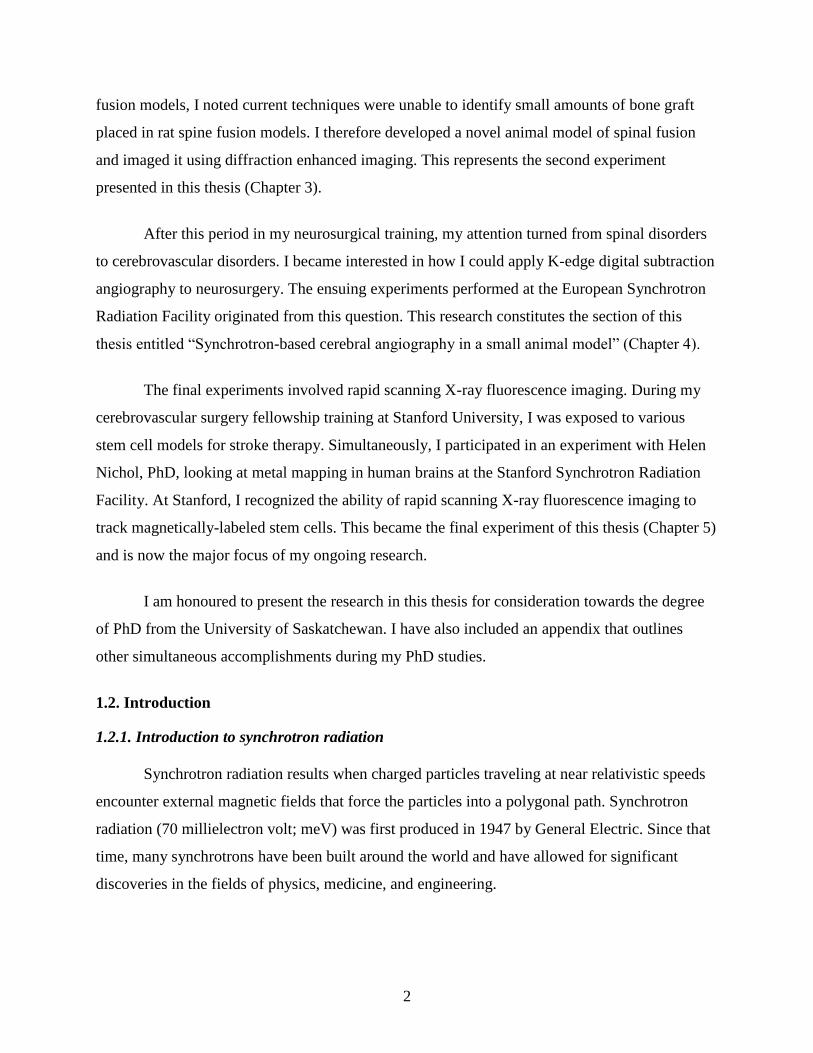
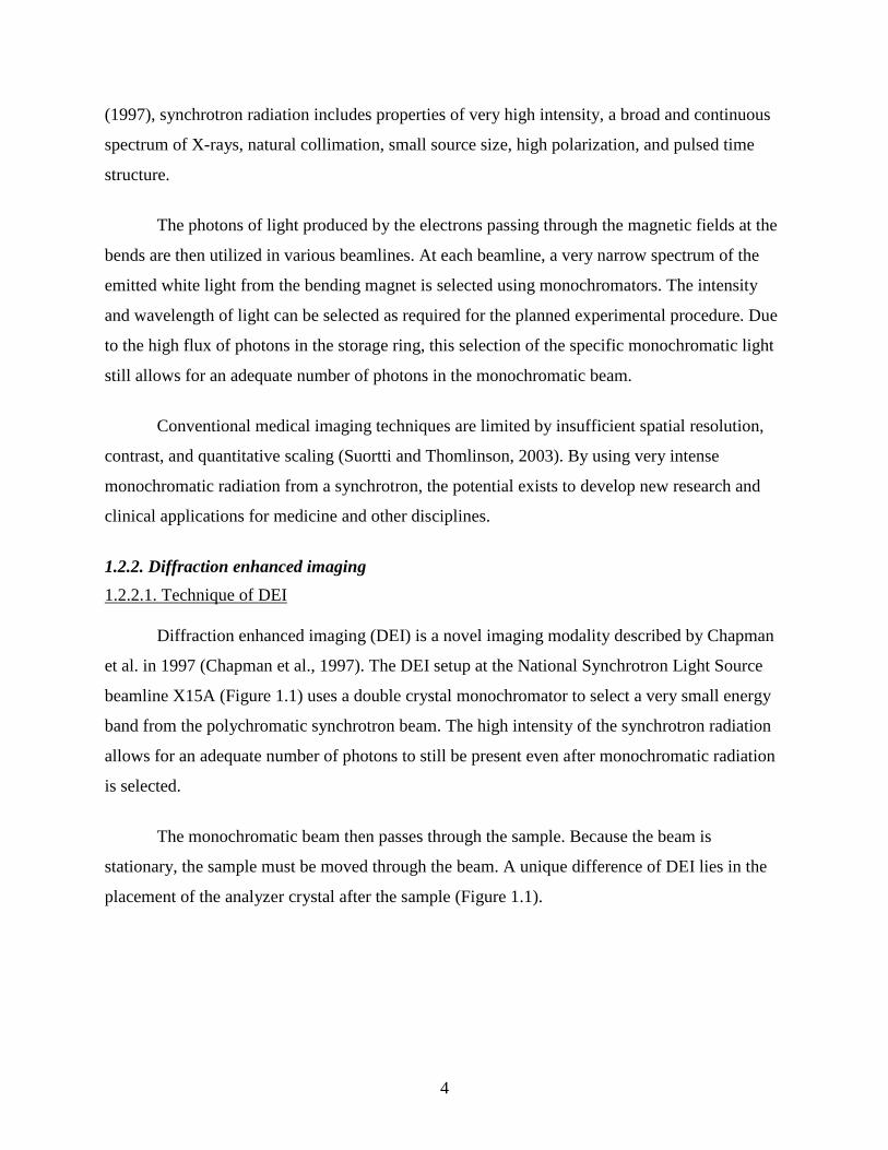
Diffraction enhanced imaging (DEI) is a novel imaging modality described by Chapman
et al. in 1997 (Chapman et al., 1997). The DEI setup at the National Synchrotron Light Source
beamline X15A (Figure 1.1) uses a double crystal monochromator to select a very small energy
band from the polychromatic synchrotron beam. The high intensity of the synchrotron radiation
allows for an adequate number of photons to still be present even after monochromatic radiation
is selected.
The monochromatic beam then passes through the sample. Because the beam is
stationary, the sample must be moved through the beam. A unique difference of DEI lies in the
placement of the analyzer crystal after the sample (Figure 1.1).
5
Figure 1.1. DEI setup at the National Synchrotron Light Source, beamline X15A.
(from Kelly et al., 2006, reprinted with permission)
The analyzer crystal is similar to that used in the monochromator. Initial experiments
showed this analyzer crystal was sensitive to the refractive index effects within the object in
addition to absorption and scattering effects (Chapman et al., 1997). This technique was further
improved by placement of a reflection case (Bragg geometry) analyzer crystal to create an
independent refraction image and apparent absorption image. The Bragg condition is only met
when the incident beam makes the correct angle to the atomic lattice planes in the crystal for the
appropriate X-ray photon or energy wavelength (Mollenhauer et al., 2002). The analyzer crystal
used in DEI is comprised of silicon, usually in a 3,3,3 lattice configuration. The silicon crystal is
able to select for either refraction or apparent absorption. This selection is done by moving the
analyzer crystal, whereby a resultant angular acceptance of the crystal or rocking curve is created
(Chapman et al., 1997). Figure 1.2 is a rocking curve from beamline X27 at the National
Synchrotron Light Source. Apparent absorption results because the analyzer crystal is sensitive
to scatter and removes it from the image. The rejected scatter is considered to be small angle
scattering that arises from scattering of very small, fine structures (Pisano et al., 2000). This

6
scattering normally appears on conventional radiography but is missing in DEI. Superior image
contrast is therefore possible because of this scatter rejection, called extinction contrast
(Chapman et al., 1997). Apparent absorption is the result of the absorption of X-rays by the
object with scatter rejection or extinction (Pisano et al., 2000).
Figure 1.2. Analyzer rocking curve at 18 keV, illustrating low and high angle sides and
associated refraction images. The apparent absorption image occurs at the peak of the rocking
curve. (from Chapman et al., 1997, reprinted with permission)
The crystal detects refraction of the X-rays as they pass through the sample. This occurs
on either the high or low side of the rocking curve. Refraction is a change in direction of the X-
ray beam when it passes between the boundaries of two materials in which the velocity of
propagation is different (Pisano et al, 2000). When objects are imaged with various points on the
rocking curve, significantly more information can be obtained about the specimen characteristics
than with conventional radiography.
1.2.2.2. Medical applications of DEI
Chapman et al. (1997) were able to show superior contrast with imaging of X-ray
phantoms with DEI. The refraction image created by the analyzer crystal is able to better
delineate the edges or boundaries of objects and often appears 3-dimensional. These
characteristics give DEI superior contrast over conventional absorption radiography and allow
7
for the development of DEI as a medical imaging modality for research and clinical applications
in the field of neurosurgery.
After this initial work with DEI and X-ray phantoms, several DEI experiments have been
published that involve imaging of biological substances (Fiedler et al., 2004; Hasnah et al., 2002;
Johnston et al., 1996; Kiss et al., 2004; Lewis et al., 2003; Li et al., 2003, 2004; Majumdar et al.,
2004; Mollenhauer et al., 2002; Muehleman et al., 2003, 2004a,b; Pisano et al., 2000). The
majority of this work has been performed at the National Synchrotron Light Source on beamlines
X27 and X15A. For example, Pisano et al. (2000) in 2000 used DEI to study human breast
cancer. The study involved seven breast cancer specimens examined at 18 keV. They showed
enhanced visualization of surface speculation that correlated with histopathological information
in six of the seven specimens (86%). DEI was also able to detect the tumor invasion into the
surrounding tissues. Further work by this group looked at image contrast of calcifications in
breast tissue specimens (Kiss et al., 2004). In this study, two of the three specimens had
calcifications associated with breast cancer while a third had calcifications associated with
benign breast disease. DEI obtained with the analyzer crystal at the peak of the rocking curve
showed a 19-fold increase in contrast compared to synchrotron based absorption angiography,
and a 5.5-fold increase in contrast in the calcified tissues compared to absorption radiography.
They noted the peak rocking curve images had markedly superior contrast to conventional
radiography but that the refraction images showed very little improvement in image contrast
(Kiss et al., 2004).
In 2003, Lewis et al. (2003) examined mouse lungs, heart, liver, and legs using DEI at the
medical beamline Synchrotron Radiation for Medical Physics (SYRMEP) at the Elettra
Synchrotron at Trieste, Italy. The purpose of the study was to identify areas of clinical radiology
that may benefit from this new type of imaging. Images were obtained with an energy ranging
from 8.5 to 35 keV, and results demonstrated the remarkable clarity of the DEI images compared
to conventional radiography. A particularly interesting part of this experiment involved the
detection of a lytic metastasis present in the proximal metaphysis of the tibia, demonstrating the
potential of DEI for the detection of bone abnormalities.
8
DEI has been also employed to study cartilage. Mollenhauer et al. (2002) utilized DEI at
the National Synchrotron Light Source, beamline X15A, to study disarticulated and intact human
knee and talocrural joints. They used an energy of 30 keV and a standard setup of DEI (Chapman
et al., 1997), with the goal to test the utility of DEI to study articular cartilage and osteoarthritis.
They were able to clearly identify articular cartilage. This study also revealed some of the
difference in DEI that could be observed when various points on the rocking curve were selected,
such as heterogeneities in contrast. Given the superior spatial resolution of X-ray radiography,
and particularly DEI, compared to magnetic resonance imaging (MRI), greater detail of articular
cartilage can be obtained through DEI technology (Mollenhauer et al., 2002). This group has also
published on DEI of rabbit articular cartilage, which is important for the development of future
experimental procedures involving therapies in an animal model (Muehleman et al., 2003).
Muehleman et al. (2004b) applied DEI to bone, and reported DEI provides contrast
enhancement at the edges of the cortical and cancellous bone and three-dimensional appearance
of the bone trabeculae. The proven ability of DEI to image bone allows for the development of
several potential applications in the area of spine research and spine imaging.
1.2.3. K-edge digital subtraction angiography
1.2.3.1. Technique of K-edge digital subtraction angiography
The first use of K-edge digital subtraction angiography (KEDSA) was described by
Rubenstein et al. (1986). This technique held promise as a non-invasive method to image the
coronary vasculature. Currently, only synchrotron radiation sources are able to produce X-rays
with sufficient monochromacity and flux to perform this technique (Lewis et al., 1997).
Dichromography is a special type of digital subtraction angiography that causes
remarkable enhancement of signals of low contrast (Dix, 1995; Dix et al., 2003; Jacobsen, 1953).
When X-rays of sufficient energy interact with an atom, absorption occurs and an electron is
subsequently liberated from its electron shell (such as the K-shell or L-shell). As a lower energy
electron drops into the vacated shell, electromagnetic radiation is released. The phenomenon
only occurs if sufficient energy to liberate an electron is supplied. For a commonly used contrast
agent, iodine, the absorption k-edge is 33.17 keV (Ek). Synchrotron radiation allows for the
creation of two monochromatic beams of precise energy. These beams are slightly above and

9
slightly below the absorption k-edge of the contrast agent. After image acquisition, analysis
involves the logarithmic subtraction of two images obtained at different energies (Dix et al.,
2003). The absorption of iodine between the high and low energies varies by a factor of 6
(Lewis, 1997). For an energy of 300 eV, the resulting image has about a 10,000-fold increase in
sensitivity to iodine over soft tissues (Dix et al., 2003; Lewis, 1997). Figure 1.3 shows the energy
of X-ray and mass attenuation coefficients of iodine.
Figure 1.3. Photon energy of X-ray and mass attenuation coefficient.
(from Ito et al., 1998, reprinted with permission)
Given this very high sensitivity of contrast agent, detecting very small concentrations
of a contrast agent is possible. Iodine injected intravenously is diluted approximately 50 times
and can be detected with KEDSA (Meili et al., 2004). In KEDSA, both the high and low energy
images are obtained simultaneously so freezing the motion of fast moving small structures, such
as the coronary vasculature, is possible (Dix et al., 2003). As with DEI, the beam is stationary
and therefore the sample or patient must be moved through the beam on a platform. At the
European Synchrotron Radiation Facility (ESRF), the platform moves a total of 200 mm at a rate
10
of 200 mm/s (Elleaume et al., 2000). The beams are 0.7 mm in height and 150 mm wide
(Elleaume et al., 2000). The two X-ray beams are focused at the patient and then cross and enter
a pure germanium detector with an image spatial resolution of 350 µm by 350 µm (Elleaume et
al., 2000). Patient X-ray dose is very carefully measured and two independent fast shutters allow
the beam to be shut down in 10 ms in case of emergency (Elleaume et al., 2000).
1.2.3.2. Medical applications of K-edge digital subtraction angiography
KEDSA was first described by Jacobson (1953). Rubenstein et al. (1985) reported their
use of the technique at the Stanford National Synchrotron Radiation Laboratory. The next year,
they reported using KEDSA successfully and safely in dogs. In the same year, the Stanford
group subsequently reported the first use of KEDSA in human subjects (Rubenstein et al., 1986).
From the very beginning, the goal was to develop a method of intravenous coronary
angiography. The conventional method of coronary angiography is invasive, expensive, painful,
and carries a small risk of complications including arterial dissection, cerebral embolism,
myocardial infarction, and death (Dix et al., 2003). Severe complications are around 0.1% while
less serious complications can be as high as 10-15% (Estève et al., 2002; Suortti and
Thomlinson, 2003). Rogers felt the necessity to develop a non-invasive and reproducible method
that allowed for precise quantification of coronary stenosis, which would be especially useful in
the follow-up of patients with coronary artery disease (Rogers, 1998).
After the initial report by Rubenstein et al. (1986), multiple human KEDSA programs
emerged around the world including one at the National Synchrotron Light Source (Rubenstein
et al., 1990). Dix et al. (1995, 1989, 2003, Dill et al., 2000; Hamm et al., 1996; Venturea et al.,
2001) developed a program in Hamburg, Germany; a Japanese group has also performed
KEDSA in humans (Ohtsuka et al., 1999; Takeda et al., 1995); and a program at the ESRF safely
performed KEDSA in human patients as well. In total, over 500 synchrotron based intravenous
angiograms have been performed safely in human patients worldwide (Suortti and Thomlinson,
2003).
A study by Estève et al. (2002) looked at iodine and gadolinium contrast agents
during synchrotron-based intravenous coronary angiography in pigs. They speculated gadolinium
may be a superior agent to iodine for this purpose because of the higher energy of gadolinium
11
compared to iodine (50.23 vs. 33.17 keV). They speculated gadolinium would result in a higher
signal to noise ratio, but the current commercially available concentrations were not high enough
to be used in KEDSA (Estève et al., 2002). To date, no further study of gadolinium as a contrast
agent has been performed.
Importantly, coronary angiography is the only medical application for which
synchrotron radiation techniques have been extensively studied in human patients (Suortti and
Thomlinson, 2003). Therefore, developing this technique for other indications for angiography
may be possible.
1.2.4. Rapid scanning X-ray fluorescence spectroscopy
1.2.4.1. Technique of rapid scanning X-ray fluorescence spectroscopy
Rapid scanning X-ray fluorescence (RS-XRF) is a new imaging technique, first
developed at the Stanford Synchrotron Radiation Facility. It differs from normal synchrotron
hard X-ray microprobes that map small areas (ca. 1 mm2) at high resolution (e.g., 1-10 μm). RS-
XRF rapidly and simultaneously maps multiple metals over very large areas at modest resolution
(e.g., 50 μm), while micro RS-XRF collects higher resolution images of small areas with much
greater speed than traditional microprobe techniques. The technique relies on unique hardware
and software to allow for the rapid scanning (Gh Popescu et al., 2009). During imaging, the
sample continuously moves. RS-XRF is element specific and can also quantify the different
chemical forms of the specific element that may be present.
An iron atom has 26 electrons in different orbits around the nucleus, and an X-ray with
an energy of 7.1 keV will knock out an electron from its innermost orbit. To reduce the
instability of the atom, an electron from a farther out orbit will move inward to fill the displaced
electron. Because the replacement electron has less energy, as it falls into its new place it emits
x-ray fluorescence by way of a photon with an energy of 6.4 keV. This energy is exactly the
difference between the two electron shells and creates a fluorescence signal at an energy specific
to iron.
The configuration of RS-XRF imaging at the Stanford Synchrotron Radiation Facility is
described below and has previously been published (Popescu et al., 2009). The experiments are
12
performed at wiggler beam line 6-2. To excite the K-shell of the first transition row and lighter
elements, the X-ray beam is set to an energy of 11 keV using a Si(111) double crystal
monochromator. The beam line is operated in its standard configuration with a collimating
mirror upstream of the monochromator, and a pair of focusing mirrors downstream. The beam is
focused onto a 50 m tungsten pinhole placed close to the sample. The pinhole is slightly tilted
to create an elliptical beam resulting in a round 50 m footprint on the sample that is mounted
vertically at a 45° angle to the incident beam. A 13 element germanium detector (Canberra)
system with Gaussian shaping amplifiers plus single channel analyzers are used to detect the
XRF signal. The detector is placed at a 90° angle to the beam to minimize the unwanted
scattering signal. The electronic (single channel analyzer) windows are set to capture the
K fluorescence signal of several chemical elements including iron, zinc, manganese, and
copper. The sample is mounted on a computerized translational stage and rapid scans are
performed by continuously translating the sample horizontally across the beam. At the end of
each line, a vertical step (40 m/step) is performed and the horizontal scan direction is reversed.
Data are taken on the fly in both horizontal directions at a rate corresponding to a travel
distance of 40 m per readout. The readout electronics are coupled with custom built real-time
software and hardware to provide deterministic data acquisition. Figure 1.4 illustrates the
experimental layout (Gh Popescu et al., 2009).
1.2.5. Synchrotron-based rapid scanning X-ray fluorescence spectroscopy
Single point X-ray fluorescence (XRF) spectroscopic mapping has been used to localize
metal in small regions of brain tissue (Collingwood and Dobson, 2006; Flinn et al., 2005;
Ishihara et al., 2002; Lengyel et al., 2007; Linkous et al., 2008; Miller et al., 2006; Yoshida et al.,
2001; Zhang et al., 2002). However, the long time needed to scan larger sections of brain makes
imaging entire brain sections impossible. The development of RS-XRF allows for entire sections
to be scanned relatively quickly. Both single point XRF and RS-XRF can non-destructively,
quantitatively, and simultaneously map multiple metals with the added ability to speciate metals
at points of interest (Gh Popescu et al., 2009). XRF also has a substantial benefit over
conventional histology because the specimens do not need to be dehydrated or embedded and
can therefore be used for future experiments (Gh Popescu et al., 2009).
13
Figure 1.4. Rapid-scanning x-ray fluorescence mapping experimental setup. Synchrotron x-rays
at 11 keV passed through a 50 μm aperture (Ap). The beam intensity was monitored with a N2-
filled ion chamber (I0). The brain slice was mounted vertically on a motorized stage (St) at 45°
to the incident x-ray beam and raster scanned in the beam. A 13-element Ge detector (Ge) was
positioned at a 90° angle to the beam. (from Popescu et al., 2009, reprinted with permission)
Initial experiments with RS-XRF at the Stanford Synchrotron Radiation Facility were
aimed at analyzing the ancient Archimedes Palimpsest, specifically to uncover the underlying
text (Bergmann, 2007; Service, 2006). Following these initial experiments, Popescu et al.
performed RS-XRF on human brain sections (Gh Popescu et al., 2009), to map and quantify iron,
zinc, and copper in brain slices from Parkinson’s disease and unaffected subjects. RS-XRF
allowed for the rapid mapping of multiple metals in the coronal brain sections, and was non-
destructive. Correlation to known locations of brain metals was excellent and also correlated well
to that of disease states (Gh Popescu et al., 2009).
The same group then performed further work to analyze iron, copper, and zinc
concentrations in the human cerebellum (Gh Popescu et al., 2009). Again, RS-XRF had a very
high sensitivity to metals. The authors noted a very high concentration of iron was present in the
dentate nucleus, and postulated possible future uses of the technique may allow for analysis of
degenerative conditions affecting the dentate nucleus.
14
1.3. References
Bergmann U: Archimedes brought to light. Physics World 20:39-42, 2007.
Chapman D, Thomlinson W, Johnston RE, Washburn D, Pisano E, Gmur N, et al: Diffraction
enhanced x-ray imaging. Phys Med Biol 42:2015-2025, 1997.
Collingwood J, Dobson J: Mapping and characterization of iron compounds in Alzheimer's
tissue. J Alzheimers Dis 10:215-222, 2006.
Dill T, Job H, Dix WR, Ventura R, Kupper W, Hamm CW, et al: [Intravenous coronary
angiography with synchrotron radiation]. Z Kardiol 89 Suppl 1:27-33, 2000.
Dix WR: Intravenous coronary angiography with synchrotron radiation. Prog Biophys Mol Biol
63:159-191, 1995.
Dix WR, Engelke K, Heuer J, Graeff W, Kupper W, Lohmann M, et al: [Noninvasive coronary
angiography with synchrotron irradiation]. Biomed Tech (Berl) 34 Suppl:79-80, 1989.
Dix WR, Kupper W, Dill T, Hamm CW, Job H, Lohmann M, et al: Comparison of intravenous
coronary angiography using synchrotron radiation with selective coronary angiography. J
Synchrotron Radiat 10:219-227, 2003.
Elleaume H, Fiedler S, Estève F, Bertrand B, Charvet AM, Berkvens P, et al: First human
transvenous coronary angiography at the European Synchrotron Radiation Facility. Phys
Med Biol 45:L39-43, 2000.
Estève F, Elleaume H, Bertrand B, Charvet AM, Fiedler S, Le Duc G, et al: Coronary
Angiography with Synchrotron X-Ray Source on Pigs after Iodine or Gadolinium
Intravenous Injection. Academic Radiology 9:S92-S97, 2002.
Fiedler S, Bravin A, Keyrilainen J, Fernandez M, Suortti P, Thomlinson W, et al: Imaging
lobular breast carcinoma: comparison of synchrotron radiation DEI-CT technique with
clinical CT, mammography and histology. Phys Med Biol 49:175-188, 2004.
Flinn JM, Hunter D, Linkous DH, Lanzirotti A, Smith LN, Brightwell J, et al: Enhanced zinc
consumption causes memory deficits and increased brain levels of zinc. Physiol Behav
83:793-803, 2005.
Gh Popescu BF, George MJ, Bergmann U, Garachtchenko AV, Kelly ME, McCrea RP, et al:
Mapping metals in Parkinson's and normal brain using rapid-scanning x-ray fluorescence.
Phys Med Biol 54:651-663, 2009.
15
Hamm CW, Meinertz T, Dix WR, Rust C, Graeff W, Illing G, et al: Intravenous coronary
angiography with dichromography using synchrotron radiation. Herz 21:127-131, 1996.
Hasnah MO, Zhong Z, Oltulu O, Pisano E, Johnston RE, Sayers D, et al: Diffraction enhanced
imaging contrast mechanisms in breast cancer specimens. Med Phys 29:2216-2221,
2002.
Ishihara R, Ide-Ektessabi A, Ikeda K, Mizuno Y, Fujisawa S, Takeuchi T, et al: Investigation of
cellular metallic elements in single neurons of human brain tissues. Neuroreport
13:1817-1820, 2002.
Ito K, Tanaka E, Mori H, Nakazawa H, Tanino R: A microangiographic technique using
synchrotron radiation to visualize dermal circulation in vivo. Plast Reconstr Surg
102:1128-1133, 1998.
Jacobson LE: Grid depth dose investigation for 200 and 400 kilovolts at the center and edge of
the field. Am J Roentgenol Radium Ther Nucl Med 69:991-1000, 1953.
Johnston RE, Washburn D, Pisano E, Burns C, Thomlinson WC, Chapman LD, et al:
Mammographic phantom studies with synchrotron radiation. Radiology 200:659-663,
1996.
Kelly ME, Beavis RC, Fourney DR, Schultke E, Parham C, Juurlink BH, et al: Diffraction-
enhanced imaging of the rat spine. Can Assoc Radiol J 57:204-210, 2006.
Kiss MZ, Sayers DE, Zhong Z, Parham C, Pisano ED: Improved image contrast of calcifications
in breast tissue specimens using diffraction enhanced imaging. Phys Med Biol 49:3427-
3439, 2004.
Lengyel I, Flinn JM, Peto T, Linkous DH, Cano K, Bird AC, et al: High concentration of zinc in
sub-retinal pigment epithelial deposits. Exp Eye Res 84:772-780, 2007.
Lewis R: Medical applications of synchrotron radiation x-rays. Phys Med Biol 42:1213-1243,
1997.
Lewis RA, Hall CJ, Hufton AP, Evans S, Menk RH, Arfelli F, et al: X-ray refraction effects:
application to the imaging of biological tissues. Br J Radiol 76:301-308, 2003.
Li J, Zhong Z, Lidtke R, Kuettner KE, Peterfy C, Aliyeva E, et al: Radiography of soft tissue of
the foot and ankle with diffraction enhanced imaging. J Anat 202:463-470, 2003.
16
Li J, Zhong Z, Lidtke R, Kuettner KE, Peterfy C, Aliyeva E, et al: Radiography of soft tissue of
the foot and ankle with diffraction enhanced imaging. J Am Podiatr Med Assoc 94:315-
322, 2004.
Linkous DH, Flinn JM, Koh JY, Lanzirotti A, Bertsch PM, Jones BF, et al: Evidence that the
ZNT3 protein controls the total amount of elemental zinc in synaptic vesicles. J
Histochem Cytochem 56:3-6, 2008.
Majumdar S, Issever AS, Burghardt A, Lotz J, Arfelli F, Rigon L, et al: Diffraction enhanced
imaging of articular cartilage and comparison with micro-computed tomography of the
underlying bone structure. Eur Radiol 14:1440-1448, 2004.
Meuli R, Hwu Y, Je JH, Margaritondo G: Synchrotron radiation in radiology: radiology
techniques based on synchrotron sources. Eur Radiol 14:1550-1560, 2004.
Miller LM, Wang Q, Telivala TP, Smith RJ, Lanzirotti A, Miklossy J: Synchrotron-based
infrared and X-ray imaging shows focalized accumulation of Cu and Zn co-localized with
beta-amyloid deposits in Alzheimer's disease. J Struct Biol 155:30-37, 2006.
Mollenhauer J, Aurich ME, Zhong Z, Muehleman C, Cole AA, Hasnah M, et al: Diffraction-
enhanced X-ray imaging of articular cartilage. Osteoarthritis Cartilage 10:163-171,
2002.
Muehleman C, Chapman LD, Kuettner KE, Rieff J, Mollenhauer JA, Massuda K, et al:
Radiography of rabbit articular cartilage with diffraction-enhanced imaging. Anat Rec
272A:392-397, 2003.
Muehleman C, Majumdar S, Issever AS, Arfelli F, Menk RH, Rigon L, et al: X-ray detection of
structural orientation in human articular cartilage. Osteoarthritis Cartilage 12:97-105,
2004a.
Muehleman C, Sumner DR, Zhong Z: Refraction effects of diffraction-enhanced radiographic
imaging: a new look at bone. J Am Podiatr Med Assoc 94:453-455, 2004b.
Ohtsuka S, Sugishita Y, Takeda T, Itai Y, Tada J, Hyodo K, et al: Dynamic intravenous coronary
angiography using 2D monochromatic synchrotron radiation. Br J Radiol 72:24-28,
1999.
17
Pisano ED, Johnston RE, Chapman D, Geradts J, Iacocca MV, Livasy CA, et al: Human breast
cancer specimens: diffraction-enhanced imaging with histologic correlation--improved
conspicuity of lesion detail compared with digital radiography. Radiology 214:895-901,
2000.
Popescu BF, Robinson CA, Rajput A, Rajput AH, Harder SL, Nichol H: Iron, copper, and zinc
distribution of the cerebellum. Cerebellum 8:74-79, 2009.
Rogers LF: The heart of the matter: noninvasive coronary artery imaging. AJR Am J
Roentgenol 170:841, 1998.
Rubenstein E, Brown GS, Harrison DC, Hofstadter R, Hughes EB, Kernoff RS, et al:
Synchrotron radiation for transvenous coronary angiography. Trans Am Clin Climatol
Assoc 97:27-31, 1985.
Rubenstein E, Giacomini JC, Gordon HJ, Thompson AC, Brown G, Hofstadter R, et al:
Synchrotron radiation coronary angiography with a dual-beam, dual-detector imaging
system. Nucl Instrum Methods Phys Res - Sect A 291:80-85, 1990.
Rubenstein E, Hofstadter R, Zeman HD, Thompson AC, Otis JN, Brown GS, et al: Transvenous
coronary angiography in humans using synchrotron radiation. Proc Natl Acad Sci USA
83:9724-9728, 1986.
Service RF: Imaging. Brilliant X-rays reveal fruits of a brilliant mind. Science 313:744, 2006.
Suortti P, Thomlinson W: Medical applications of synchrotron radiation. Phys Med Biol 48:R1-
35, 2003.
Takeda T, Itai Y, Wu J, Ohtsuka S, Hyodo K, Ando M, et al: Two-dimensional intravenous
coronary arteriography using above-K-edge monochromatic synchrotron X-ray. Acad
Radiol 2:602-608, 1995.
Ventura R, Dill T, Dix WR, Lohmann M, Job H, Kupper W, et al: Intravenous coronary
angiography using synchrotron radiation: technical description and preliminary results.
Ital Heart J 2:306-311, 2001.
Yoshida S, Ektessabi A, Fujisawa S: XANES spectroscopy of a single neuron from a patient
with Parkinson's disease. J Synchrotron Radiat 8:998-1000, 2001.
Zhang F, Liu N, Zhao X, Zuo A, Yang L, Xu Q, et al: Variations of elemental distribution in
brain regions of neonatal rats at different iodine intakes. Biol Trace Elem Res 90:227-
237, 2002.

18
CHAPTER 2.
DIFFRACTION ENHANCED IMAGING OF THE RAT SPINE
Adapted from
Kelly ME, Beavis RC, Fourney DR, Schültke E, Parham C, Juurlink BHJ, Zhong Z, Chapman,
LD. 2006. Canadian Association of Radiologists Journal 57(4): 204-210.
2.1. Introduction
Synchrotron-supported imaging techniques are currently under development for medical
imaging. The novel technique of diffraction enhanced imaging (DEI) was first described by
Chapman et al. (1997). This x-ray based imaging technique uses monochromatic x-rays from a
synchrotron to produces images of thick absorbing objects. DEI can provide dramatically
improved contrast over standard imaging techniques applied to the same object. Whereas
conventional radiography relies on x-ray absorption, DEI contrast is based additionally on the x-
ray refraction and rejection of scattered x-rays (Chapman et al., 1997). This technique has
recently been applied to image a human cadaveric foot and articular cartilage specimens
subsequent to the initial experiments on breast tissue (Hasnah et al., 2002; Lewis et al., 2003;
Mollenhauer et al., 1997; Muehleman et al., 2003).
We applied the technique of DEI to study the rat spinal column in both control and post-
surgical specimens. To our knowledge, this represents the first attempt to analyze the vertebral
column with DEI.
2.2. Materials and methods
All procedures involving animals were approved by the University of Saskatchewan
Animal Care Committee. Animals were treated in accordance with the Canadian Council on
Animal Care Guidelines.
19
Four male Wistar rats weighing approximately 500 grams were studied. One underwent a
thoracic laminectomy, one underwent a lumbar laminectomy and one did not undergo surgery.
The spine-muscle blocks were isolated in these three animals: A fourth rat spine was studied as a
whole animal control specimen.
Those animals which underwent surgery were pre-medicated with a subcutaneous
injection of 0.05mg/kg Buprenorphine. Anesthesia was achieved with 1.5-2% Halothane in
oxygen with a flow rate of 1.5 liter / min. The back and the lower abdomen of the animals were
shaved and disinfected with chlorhexidine and 70% alcohol. A dorsal midline incision was
performed at the planned spinal levels. The fascia was incised and the muscles were separated
from spinous processes and laminae. Laminectomy was performed at the T6/7 level in one
animal and L2/3 level in another. Hemostasis was obtained and the fascia and muscles were
closed with suture 4-0 polyglactin 910, (Ethicon Inc., Somerville, New Jersey). The skin was
closed with staples. Post-operative analgesia involved a tapering dose of buprenorphine every 12
hours for three days.
Animals were sacrificed 3 weeks after surgery under general anesthesia (1.5-2%
Halothane in oxygen with a flow rate of 1.5 liters / min). Transcardiac perfusion was performed
with 400 mL of buffered 10% formalin. In 3 animals, the spinal column and surrounding muscle
was removed en bloc and placed in buffered 10% formalin. The fourth animal was fixed intact.
Imaging was performed at the National Synchrotron Light Source at the Brookhaven
National Laboratory in Upton, New York. Initial standard absorption radiographs were taken
with a 40 kilo-electron-volt (keV) monochromatic x-ray beam for comparison. A standard DEI
technique was performed using x-ray energy of 40 keV at a typical surface dose of 1 milli-Gray
(mGy) (1 Gray=1 joule absorbed per kilogram of matter per image). The dose at the detector was
0.76 mGy. The DEI setup is shown in Figure 2.1. Each specimen was imaged in the anterior-
posterior and lateral projections and the images were acquired using standard image plates (Fuji
HRV image plate, readout by a Fuji BAS2500 image-plate reader). Final image processing was
performed using Interactive Data Language software, (Research Systems Inc., Boulder, CO).
Conventional radiographs and DEI images were then compared side to side by two investigators
(MEK, RCB) to assess image quality, contrast and the ability to visualize anatomic structures.

20
Figure 2.1. DEI setup at the National Synchrotron Light Source, Brookhaven National
Laboratory that was used for imaging (a). (reprinted with permission)
2.2.1. Technique of DEI
As shown in Figure 2.1, a double crystal monochromator is used to select a very small
energy band from the polychromatic synchrotron beam. The high intensity of the synchrotron
radiation allows for an adequate number of photons to still be present even after monochromatic
radiation is selected.
The monochromatic beam then passes through the sample. Because the beam is
stationary the sample must be moved through the beam. The difference between DEI lies in the
placement of the analyzer crystal after the sample (Figure 2.1)
The analyzer crystal used is similar to that used in the monochromator. Initial
experiments showed that this analyzer crystal was sensitive to the refractive index effects within

21
the object in addition to absorption and scattering effects (Chapman et al., 1997). This technique
was further improved by placing a reflection case (Bragg geometry) analyzer crystal to create an
independent refraction image and apparent absorption image. The Bragg condition is only met
when the incident beam makes the correct angle to the atomic lattice planes in the crystal for the
appropriate X-ray photon or energy wavelength (Mollenhauer et al., 2002). The analyzer crystal
used in DEI is comprised of silicon, usually in a 3,3,3 lattice configuration. The silicon crystal is
able to select for either refraction or apparent absorption. This selection is done by moving the
analyzer crystal; a resultant angular acceptance of the crystal or rocking curve is created
(Chapman et al., 1997). Apparent absorption results because the analyser crystal is sensitive to
scatter and removes it from the image. The rejected scatter is considered to be small angle
scattering that arises from scattering of very small, fine structures (Muehleman et al., 2003). This
scattering normally appears on conventional radiography but is missing in DEI. Improved image
contrast is therefore possible because of this scatter rejection and this is called extinction contrast
(Chapman et al., 1997). It has been shown that extinction may contribute to the superior image
contrast seen with DEI (Chapman et al., 1997). Apparent absorption is the result of the
absorption of X-rays by the object with scatter rejection or extinction (Muehleman et al., 2003).
The crystal detects refraction of the X-rays as they pass through the sample. This occurs
on either the high or low side of the rocking curve. Refraction is a change in direction of the X-
ray beam when it passes between the boundaries of 2 materials in which the velocity of
propagation is different (Muehleman et al., 2003). When objects are imaged with various points
on the rocking curve, significantly more information can be obtained about the specimen
characteristics than compared to conventional radiography.
2.3. Results
Conventional absorption radiography demonstrated the bony structures of the rat as
expected. Laminectomy defects could be seen, but no soft tissue visualization was possible. DEI
produced superior visualization of the bony anatomy of the cervical, thoracic and lumbar
vertebrae, including the trabecular structure of the bone. DEI also allowed visualization of soft
tissue structures; bone-soft tissue interfaces and gastrointestinal structures. Over 2000 images
were produced in this study to determine the best configuration for DEI imaging of the spine.

22
Once the DEI system is properly setup only a few images need to be acquired. A sample of
representative images highlighting specific findings are included (Figures 2.2-2.7)
A comparison between a conventional radiography and DEI using a standard X-ray
phantom is shown in Figure 2.2.
Figure 2.2. Standard absorption radiography (a) and DEI (b) of a standard X-ray phantom
showing improved contrast with DEI. (reprinted with permission)
A comparison of the absorption radiographs and DEI images of the whole rat are
presented in Figures 2.3a and b. Images of this whole animal specimen did not contain
significant artifact from hair, skin or overlying structures. Some artifact from air bubbles on the
DEI images which were not present on the conventional radiographs was seen. Despite this, DEI
provided excellent visualization of the bony anatomy of the spine. Figure 2.4 reveals DEI images
of the lumbosacral junction and pelvic regions of the whole animal specimen.
Conventional radiograph and DEI images of spine muscle block specimens following
lumbar laminectomy are presented in Figures 2.5a and b. DEI produced excellent anatomic detail
including the bony trabecular architecture and superior visualization of the laminectomy defect.
DEI images of the post-surgical specimens showed additional unexpected findings. 4-0
polyglactin suture material used during the closure could be clearly visualized (Figure 2.6). Post-
surgical kyphosis was seen in one animal with disruption of the supraspinous ligaments.

23
Soft tissue visualization was superior with DEI compared with conventional radiographs.
The supraspinous ligament were clearly demonstrated using DEI (Figure 2.7) and could not be
seen on standard radiographs. The anterior aspect of the annulus fibrosis was noted at some
vertebral levels in DEI images of the spine muscle block specimens, however intervertebral discs
could not be clearly identified at most levels due to overlying bony structures. The neural
elements could not be visualized using either DEI or conventional radiography.
24
(a) (b)
Figure 2.3. Standard absorption radiography (a) and DEI (b) of whole rat thoracic and lumbar
spine (AP projection). Note the improved contrast of both bone and soft tissue detail on the DEI
image. The bright triangle in the upper right corner is a lead marker. (reprinted with
permission)
25
(a) (b)
Figure 2.4. Standard absorption radiography (a) and DEI (b) of the lumbosacral junction and
pelvis in whole rat (AP projection). The small round artifacts on the DEI image are secondary to
air bubbles that are easily detectable with DEI. (arrow) (reprinted with permission)
26
Figure 2.5. Conventional absorption radiography (a) and DEI (b) of the rat thoracic and lumbar
spine-muscle blocks (lateral projection). The DEI image provides much better contrast of the
both cortical and trabecular bone. (reprinted with permission)
27
(a) (b)
Figure 2.6. Conventional absorption radiography (a) and DEI of the rat spine after laminectomy
(lateral projection). The DEI images demonstrate the 4-0 polyglactin suture material (arrows)
and the post-surgical kyphosis and defect much more clearly than the conventional radiographs.
(reprinted with permission)
28
Figure 2.7. DEI of rat spine illustrating the supraspinous ligaments. (reprinted with permission)
2.4. Discussion
DEI capitalizes on important additional physical properties compared with standard
absorption radiography. At present DEI can only be performed using high energy,
monochromatic x-rays from a synchrotron. When these high energy x-rays pass through an
object they can be absorbed, refracted or scattered. Refraction represents the bending of the x-
rays as they pass through the object and scatter refers to the scattering of x-rays by the tissue. By
analyzing the refraction and scatter from the subject, significantly more information is obtained
about bone and soft tissues than is possible with conventional absorption radiography.

29
DEI has been shown to provide soft tissue contrast and resolution in studies involving
breast tissue (Hasnah et al., 2002; Pisano et al., 2000). Conventional radiography does not allow
for soft tissue visualization because of limited x-ray absorption by soft tissues. Magnetic
resonance imaging (MRI) does provide soft tissue imaging but also has significant limitations in
bone imaging. Although further study is required into this novel imaging technique, in this DEI
study we obtained excellent bony detail combined with soft tissue visualization. This advantage
over traditional imaging techniques holds significant research and clinical potential.
We obtained excellent images of the spine in the whole animal specimen. This important
finding of our study suggests imaging of in vivo specimens is possible. At present this is limited
by the size of the experimental area and image detector. As the technology and technique evolves
application to larger specimens will be possible.
The unexpected finding of being able to image the 4-0 polyglactin suture material
reinforces the unique capacity of DEI (Figure 2.5). The clinical usefulness of this remains
unclear, however, we know of no other current medical imaging technique which can image
suture material in situ. Furthermore, visualizing suture material and the adjacent rat spinal
anatomy does offer some scale to the resolution which DEI produces.
This experimental study is limited by the small number of specimens and the lack of
standardized, validated comparison between the conventional radiographs and DEI images.
However, as a result of this small study which confirmed the potential for DEI to be used to
image spinal anatomy, further research is underway in this area. A comparison of DEI to more
advanced imaging techniques such as computed tomography and MRI is necessary and is also
under investigation.
To the best of our knowledge, this is the first use of DEI to image the spine. This novel
technique has potential as a research tool and in the future may have a role in clinical imaging.
Study is ongoing into further applications of DEI in a number of specific areas. Current models
of spinal fusion rely on conventional absorption radiography or palpation to assess fusion (Dimar
et al., 1996; Lenke et al., 1992; Salamon et al., 2003). Given the superior bony visualization, DEI
may prove useful for postoperative imaging following spinal fusion. DEI should be able to detect

30
very small quantities of bone graft material and its incorporation into the existing bone in a small
animal model. DEI could then be used to analyze several materials which act as adjuncts to bone
fusion.
Imaging structures adjacent to spinal instrumentation is also under investigation. With the
capacity to image both bony and soft tissue, DEI may have future applications in the assessment
of a number of traumatic, degenerative and neoplastic conditions of the spine. Current
applications of DEI by our group include bone fusion, ocular imaging and growth plate injury
studies. We are also planning further studies using cadaveric spine and growth plate specimens.
The Medical Beamline at the Canadian Light Source in Saskatoon, Saskatchewan, Canada is
currently being built. This beamline will be an advanced synchrotron imaging facility dedicated
to medical applications. Our group anticipates being able to perform DEI on humans and small
and large animals within the next several years at this center.
2.5. Conclusion
DEI is a novel technique that allows for enhanced visualization of bony and soft tissue
structures over conventional absorption radiography. Potential future applications include the
analysis of spinal fusion as well as degenerative and neoplastic conditions of the spine.
2.6. Acknowledgements
Dr. Kelly held the American Association of Neurological Surgeons, National Research
and Education Foundation, Depuy Spine Fellowship for 2004/2005. Drs. Kelly, Beavis, and
Schültke are supported by the Saskatchewan Synchrotron Institute. The authors would like to
acknowledge Beth Hoyte from Department of Neurosurgery at Stanford University for her
assistance with the figures.
2.7. References
Chapman D, Thomlinson W, Johnston RE, Washburn D, Pisano E, Gmur N, et al: Diffraction
enhanced x-ray imaging. Phys Med Biol 42:2015-25, 1997.
Dimar JR 2nd, Ante WA, Zhang YP and Glassman SD: The effects of nonsteroidal anti-
inflammatory drugs on posterior spinal fusions in the rat. Spine 21:1870-6, 1996.
31
Hasnah MO, Zhong Z, Oltulu O, Pisano E, Johnston RE, Sayers D, et al: Diffraction enhanced
imaging contrast mechanisms in breast cancer specimens. Med Phys 29:2216-21, 2002.
Lenke LG, Bridwell KH, Bullis D, Betz RR, Baldus C and Schoenecker PL: Results of in situ
fusion for isthmic spondylolisthesis. J Spinal Disord 5:433-42, 1992.
Lewis RA, Hall CJ, Hufton AP, Evans S, Menk RH, Arfelli F, et al: X-ray refraction effects:
application to the imaging of biological tissues. Br J Radiol 76:301-8, 2003.
Mollenhauer J, Aurich ME, Zhong Z, Muehleman C, Cole AA, Hasnah M, et al: Diffraction-
enhanced X-ray imaging of articular cartilage. Osteoarthritis Cartilage 10:163-71,
2002.
Muehleman C, Chapman LD, Kuettner KE, Rieff J, Mollenhauer JA, Massuda K, et al:
Radiography of rabbit articular cartilage with diffraction-enhanced imaging. Anat Rec
272A:392-7, 2003.
Pisano ED, Johnston RE, Chapman D, Geradts J, Iacocca MV, CA Livasy, et al: Human breast
cancer specimens: diffraction-enhanced imaging with histologic correlation--improved
conspicuity of lesion detail compared with digital radiography. Radiology 214:895-901,
2000.
Salamon ML, Althausen PL, Gupta MC and Laubach J: The effects of BMP-7 in a rat
posterolateral intertransverse process fusion model. J Spinal Disord Tech 16:90-5, 2003.

32
CHAPTER 3.
ANALYZER BASED IMAGING OF SPINAL FUSION IN AN ANIMAL MODEL
Adapted from
Kelly ME, Beavis RC, Fiorella D, Schültke E, Allen LA, Juurlink BH, Zhong Z, Chapman, LD.
2008. Physics in Medicine and Biology 53: 2607-2616.
3.1. Introduction
Spine fusion is a frequently performed procedure with a wide variety of indications.
There has been a 77% increase in the number of patients undergoing spinal fusion in the United
States since 1996 (Deyo et al., 2004). Multiple techniques exist both with and without
instrumentation (Lipson, 2004). The ultimate success of this surgical procedure is dependent
upon obtaining solid bony fusion. Evaluation of the status of spine fusion remains a challenging
and yet unsolved clinical dilemma. The ability to definitely diagnose post-operative
pseudoarthrosis would improve the care of patients with persistent or recurrent symptoms
following spine fusion.
A paucity of literature exists regarding the assessment of bony fusion. Conventional
radiography is relatively imprecise at detecting bony fusion (Blumenthal and Gill, 1993; Kant et
al., 1995). Computerized tomography (CT) and magnetic resonance imaging (MRI) are also
limited in their ability to evaluate bony fusion (Brodsky et al., 1991; Cook et al., 2004; Laasonen
and Soini, 1989). The gold standard for assessment of fusion is surgical exploration (Brodsky et
al., 1991; Laasonen and Soini, 1989). An accurate, reliable way to assess fusion in a non-
invasive fashion does not exist (Larsen et al., 1996). Assessment of bony fusion in post-surgical
patients is of critical importance not only in spinal surgery but also in peripheral joint
arthrodesis. Furthermore, research into improved spinal fusion techniques and biologic adjuncts
to fusion is impaired by the lack of a reliable tool for assessment of fusion.
33
Analyzer based imaging (ABI) is a novel technique which relies on the high degree of
collimation that perfect crystals impart to x-ray beams which can then be analyzed by a matching
crystal placed after an object being imaged (Chapman et al., 1997; Nesterets et al., 2006). When
utilized with synchrotron radiation sources that create intense monochromatic x-rays, the
technique has shown to yield superior contrast especially in soft tissues but also in cartilage and
bone (Li et al., 2005; Muehleman et al., 2004; Wernick et al., 2003). Conventional absorption
radiography relies on x-ray absorption by the biologic material to create an image. ABI utilizes
attenuation, scatter and refraction of x-rays by the specimens to create images. ABI can provide
improved contrast over standard imaging techniques applied to the same object (Pisano et al.,
2000). ABI, Diffraction Enhanced Imaging (DEI) (Chapman et al., 1997) and Multiple Image
Radiography (Wernick et al., 2003) are analysis methods which extract absorption, refraction
and ultra-small angle scattering information and have demonstrated excellent characterization of
ligamentous and bony anatomy in a human cadaveric foot and other tissues (Hasnah et al., 2002;
Kelly et al., 2006; Mollenhauer et al., 2002; Muehleman et al., 2003). In earlier work by our
group, we utilized the DEI technique to show superior characterization of bony and ligamentous
anatomy in a rat model compared to conventional radiography (Kelly et al., 2006). A recent
report has also demonstrated increased image contrast in assessing bony gaps with ABI
compared with conventional radiography (Connor et al., 2006).
In this study, we utilized synchrotron-based analyzer based imaging to evaluate a novel
model of spinal fusion in male Wistar rats.
3.2. Materials and methods
3.2.1 Animal model
Twenty-one male Wistar rats (11 weeks of age, 300 – 360g, Charles River, Canada) were
used in the study. They were housed and cared for in a temperature-regulated animal facility
exposed to a 12-hour light/dark cycle in accordance with the guidelines of the Canadian Council
on Animal Care. Ethics approval was obtained prior to the start of the experiment. The animals
were randomly divided into 4 study groups. The control group (Group 1) did not receive any
surgical treatment. Group 2 underwent decortication only, group 3 underwent decortication and

34
autologous iliac crest bone graft fusion and group 4 underwent decortication, instrumentation
and autologous iliac crest bone graft fusion (Table 3.1).
Table 3.1. Animal groups used in study, n=21
Group 1 Group 2 Group 3 Group 4
Control Decortication ICBGF ICBGF + Instrumentation
2 Weeks 1 2 2 2
4 Weeks 1 2 2 2
6 weeks 1 2 2 2
ICBGF = Iliac crest bone graft and fusion
3.2.2 Surgical procedure
The procedures were performed by two surgeons (MEK, RCB) and were done in a
standardized fashion using loupe magnification. Anesthesia was achieved with 1.5-2% Halothane
in oxygen with a flow rate of 1.5 liter / min. The back and the lower abdomen of the animals
were shaved and disinfected with chlorhexidine and 70% alcohol. Animals were pre-medicated
with a subcutaneous injection of 0.05 mg/kg buprenorphine and post-surgically received tapered
doses in 12-hr intervals for 3 days.
A dorsal approach to the lumbar spine was performed and the paraspinal muscles were
reflected off the spinous processes sufficiently lateral to expose the L4-L6 laminae, facet joints
and transverse processes. The muscles overlying the laminae, transverse processes and dorsal
facet joint capsules were removed to allow for decortication. The dorsal surfaces of the L4-6
lamina, spinous processes and transverse processes were decorticated using a Dremel minidrill
with a round carbide bit (Black and Decker Corp., Hamstead, MD, USA) until punctate bleeding
was observed.
Group 3 and 4 animals underwent autologous bone grafting from the right iliac crest. The
harvested bone graft was stripped of its periosteum and then weighed to ensure standardized
weight of 0.15 grams of morcellized autologous bone graft. The bone graft material was then
placed in a postero-lateral fashion between the L4-6 transverse processes and over the facet
joints and laminae both on the left and right sides.
35
Group 4 animals additionally underwent spinal instrumentation. Using a technique
described by Dimar et al. (1996), a 26-gauge stainless steel cerclage wire was placed through the
L5 and L6 spinous processes to act as a form of internal spinal stabilization.
The paravertebral muscles were then allowed to cover the bone graft material and the
dorsal lumbar fascia was closed using 4-0 polyglactin 910 sutures (Ethicon Inc., Somerville,
New Jersey). The skin was closed with staples. Postoperative animal care was provided and the
animals were not immobilized in any way.
At two, four and six weeks after the intervention, animals were sacrificed by halothane
overdose with 5% Halothane in oxygen with a flow rate of 1.5 liters / min, followed by perfusion
through the aorta with 400 mL of buffered 10% formalin. The paraspinal muscles, thoracolumbar
vertebrae and pelvis were excised en bloc immediately. The spine-muscle blocks were stored in
cold phosphate-buffered 10 % formalin solution until further use.
3.2.3 Assessment of fusion by manual testing
As described by Salamon et al. (2003), manual testing of fusion was performed on the
spine-muscle blocks immediately after death. Assessment was performed by two examiners and
fusion was defined as no movement at the site of fusion. It was scored as either presence or
absence of movement.
3.2.4 Technique of analyzer based imaging
Analyzer Based Imaging (ABI) was then performed at the X15A beamline of the
National Synchrotron Light Source at the Brookhaven National Laboratory, in Upton, NY, USA.
The same imaging setup was used for both the ABI method and the absorption imaging. The ABI
or sometimes referred to as Diffraction Enhanced Imaging (DEI) system is comprised of the
synchrotron source (a 7.1 keV critical energy bend magnet source), beam filters for power
reduction, slits for beam definition, a double crystal monochromator (two parallel Si(3,3,3)
crystals with 1cm gap or ~20 mm vertical offset), ionization chamber beam monitor, rotary
actuated rotary shutter for exposure control, a scanning stage for the object, an analyzer (a Si
(3,3,3) in the parallel crystal geometry to match the monochromators) and a detector on a
scanning stage to complete the system. For radiographic mode, the analyzer is dropped out of the
36
beam from the monochromator and the detector is placed in the beam line of sight for a direct
transmission or absorption image. For ABI, the analyzer is placed in the beam from the
monochromator, but after the subject, at the Bragg condition and the detector is moved to
intercept that diffracted beam. Since the beam from the bend magnet is a horizontal fan beam,
the subject is scanned vertically while the detector is scanned to create a projection area image of
the subject. For absorption imaging the analyzer is bypassed and the transmitted beam through
the subject was recorded directly on the detector. For ABI, the transmitted beam is recorded on
the detector after diffraction from the analyzer crystal. An imaging energy of 40keV was chosen
as this energy is near the optimum absorption contrast-to-noise at fixed entrance dose for this
animal system (~5 cm of tissue and ~7 mm of solid bone).
Antero-posterior (AP) and lateral images were obtained using a digital detector with ~9
micron x 9 micron square pixels (Photonic Science XDI VHR 1:1, East Sussex, UK) and final
image processing was performed using the Interactive Data Language software (ITT Visual
Information Solutions, Boulder, CO, USA).
3.2.5 Technique of absorption radiography
AP and lateral absorption radiographs were taken of the spine-muscle blocks at the
National Synchrotron Light Source, Brookhaven National Laboratory, Upton, NY. Radiographs
were acquired using 40 keV x-rays generated by the same monochromator used for ABI, and
with the same dose as ABI.
3.2.6 Assessment of fusion
Analyzer based images at 22 points on the rocking curve were obtained for each
specimen. The specific images which optimally demonstrated the area and tissues of interest
were consistently just off the peak of the rocking curve. These selected ABI and absorption
images were then assessed by a neuroradiologist who was blinded to the experiment and not
involved in the present study. Radiographic fusion was graded by a modified method originally
described by Lenke et al. (1992). The fusion patterns were graded as follows: A) definitely solid
– solid big trabeculated bilateral fusion masses; B) possibly solid – unilateral large fusion mass
with contralateral small fusion mass; C) probable not solid – small, thin fusion masses
37
bilaterally; D) definitely not solid – graft reabsorption bilaterally or fusion mass with obvious
bilateral pseudoarthrosis, E) no bone material observed (Lenke et al., 1992; Salamon et al.,
2003).
3.3. Results
3.3.1. Manual testing of fusion
Manual testing of fusion by palpation was performed on all specimens. The examiners
were not able to distinguish based on palpation any difference among the specimens. No
assessment of fusion could be made.
3.3.2. Absorption radiography
The radiographs were assessed and graded with the previously mentioned grading scale.
Bone fusion could not be evaluated due to low image contrast and the inability to adequately
visualize the individual bone graft fragments or conglomerate fusion masses in any of the
animals. As such, all specimens were graded as showing ―no convincing evidence of bony
fusion‖ (all scored grade D or E).
3.3.3. Analyzer based imaging
The results of the radiologic assessment of the images obtained by ABI are summarized
in Table 3.2. There was no evidence of bone fusion observed in the control or decortication
groups (groups 1 and 2). A comparison of absorption radiography to analyzer based radiography
for a control specimen is shown in Figure 3.1.
The fusion group without instrumentation (group 3) showed a progression of the fusion
mass from two to six weeks after surgery. By six weeks, a definite fusion mass was observed in
both animals and was graded as possibly solid. Figure 3.2 compares the appearance of the fusion
mass at 2 weeks after surgery between absorption radiography (Figure 3.2a) and analyzer based
imaging (Figure 3.2b). Figures 3.2c and d are magnified views demonstrating the unincorporated
bone graft material.
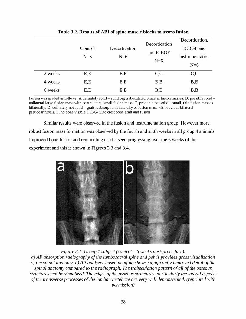
38
Table 3.2. Results of ABI of spine muscle blocks to assess fusion
Control
N=3
Decortication
N=6
Decortication
and ICBGF
N=6
Decortication,
ICBGF and
Instrumentation
N=6
2 weeks E,E E,E C,C C,C
4 weeks E,E E,E B,B B,B
6 weeks E.E E,E B,B B,B
Fusion was graded as follows: A definitely solid – solid big trabeculated bilateral fusion masses; B, possible solid –
unilateral large fusion mass with contralateral small fusion mass; C, probable not solid – small, thin fusion masses
bilaterally; D, definitely not solid – graft reabsorption bilaterally or fusion mass with obvious bilateral
pseudoarthrosis. E, no bone visible. ICBG- iliac crest bone graft and fusion
Similar results were observed in the fusion and instrumentation group. However more
robust fusion mass formation was observed by the fourth and sixth weeks in all group 4 animals.
Improved bone fusion and remodeling can be seen progressing over the 6 weeks of the
experiment and this is shown in Figures 3.3 and 3.4.
Figure 3.1. Group 1 subject (control – 6 weeks post-procedure).
a) AP absorption radiography of the lumbosacral spine and pelvis provides gross visualization
of the spinal anatomy. b) AP analyzer based imaging shows significantly improved detail of the
spinal anatomy compared to the radiograph. The trabeculation pattern of all of the osseous
structures can be visualized. The edges of the osseous structures, particularly the lateral aspects
of the transverse processes of the lumbar vertebrae are very well demonstrated. (reprinted with
permission)
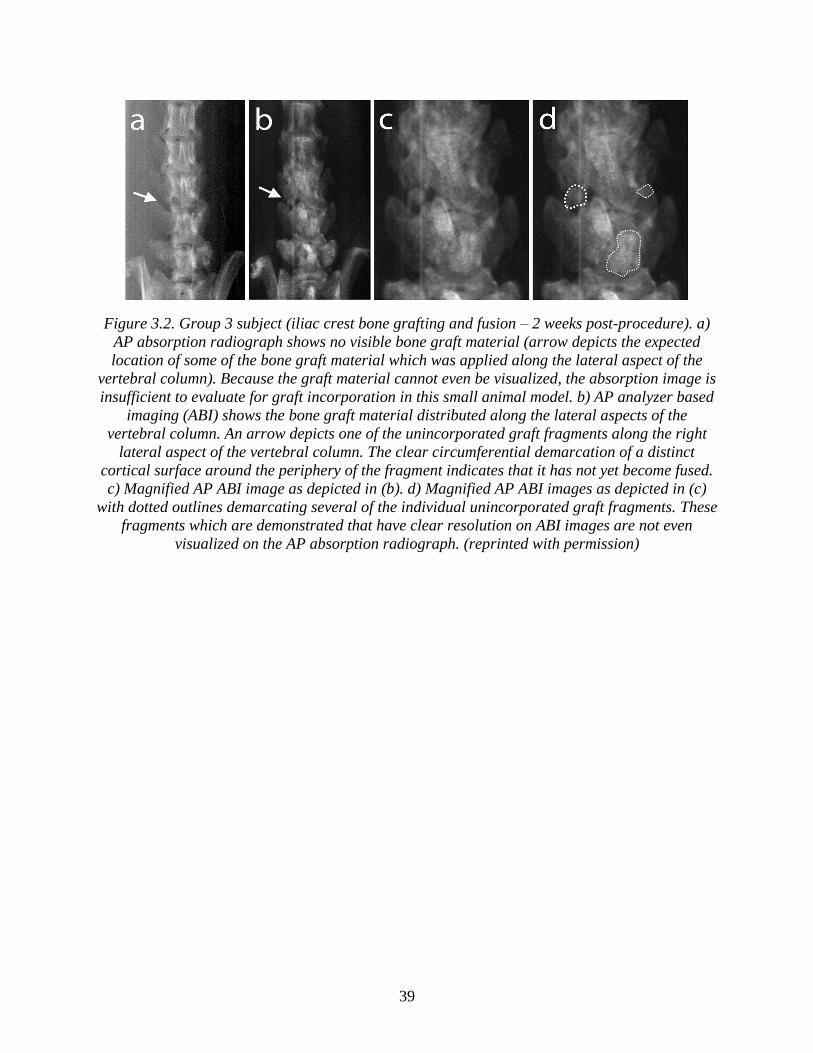
39
Figure 3.2. Group 3 subject (iliac crest bone grafting and fusion – 2 weeks post-procedure). a)
AP absorption radiograph shows no visible bone graft material (arrow depicts the expected
location of some of the bone graft material which was applied along the lateral aspect of the
vertebral column). Because the graft material cannot even be visualized, the absorption image is
insufficient to evaluate for graft incorporation in this small animal model. b) AP analyzer based
imaging (ABI) shows the bone graft material distributed along the lateral aspects of the
vertebral column. An arrow depicts one of the unincorporated graft fragments along the right
lateral aspect of the vertebral column. The clear circumferential demarcation of a distinct
cortical surface around the periphery of the fragment indicates that it has not yet become fused.
c) Magnified AP ABI image as depicted in (b). d) Magnified AP ABI images as depicted in (c)
with dotted outlines demarcating several of the individual unincorporated graft fragments. These
fragments which are demonstrated that have clear resolution on ABI images are not even
visualized on the AP absorption radiograph. (reprinted with permission)

40
Figure 3.3. Group 4 subject (iliac crest bone grafting and fusion with instrumentation – 6 weeks
post-procedure). AP absorption radiography does not show a clear fusion mass (a). A small
amount of heterotopic bone formation is depicted just superior to the right iliac crest (a,
arrowhead). A tiny amount of fusion material is vaguely seen along the left lateral aspect of the
vertebral column (a, arrow). ABI (b) shows clear evidence of a well incorporated fusion mass
along the right lateral aspect of the vertebral column (arrow). Extensive heterotopic bone
formation is evident along the superior aspect of the iliac crest and elsewhere (see below). The
same ABI image is shown again with demarcations (c) indicating the location of heterotopic
bone along the right iliopsoas musculature (hatched lines), along the lateral aspects of both iliac
wings (dotted ovals), above the left iliac crest (dotted triangle), and over the right iliac crest
(freeform dotted outline). The dotted rectangle depicts the solid fusion mass which has been
incorporated along the right lateral aspect of the vertebral column. (reprinted with permission)

41
Figure 3.4. Group 4 subjects (iliac crest bone grafting and fusion with instrumentation).
Magnified AP radiograph (a) and ABI (b) at 2 weeks post-procedure. The AP absorption
radiograph (a) demonstrates amorphous density distributed along the lateral aspects of the
vertebral columns corresponding to the location of bone graft material. Due to the lack of
contrast, no comment can be made as to the incorporation of the graft. ABI (b) of the same
specimen demonstrates well circumscribed fragments of bone graft material distributed along
the lateral aspects of the vertebral column, indicating that the graft material has not yet been
incorporated as a fusion mass. At 4 weeks post-procedure, AP absorption radiograph (c) shows
amorphous density material along the lateral aspects of the vertebral column. The material
appears less dense than on the 2-week AP radiograph, however, it is difficult to assess the level
of incorporation given the lack of contrast. ABI (d) of the same specimen shows interval
evolution of the fusion mass with incorporation of a thick mantle of bone graft along the lateral
aspects of the vertebral column. The intervertebral disc space has become obscured. At 6 weeks
post-procedure, the graft material is again, inconspicuous on the AP radiograph (e) making any
assessment of the level of incorporation difficult. ABI of the same specimen (f) demonstrates a
thick, continuous mantle of graft material along the lateral aspects of the vertebral column,
consistent with complete incorporation of the bone graft material which now has created a solid
fusion mass. (reprinted with permission)
42
We were able to detect the small amount of bone graft material (0.075g / side) initially
placed in all the fusion (group 3) and the fusion and instrumentation (group 4) animals at 2, 4
and 6 weeks post-surgery. ABI of the instrumented animals (group 4) did not show any artifact
from the implanted metal. (Figures 3.3and 3.4)
3.4. Discussion
The most important findings derived from the present set of experiments were: (1) ABI
provides diagnostic quality imaging of individual bone graft fragments and conglomerate fusion
masses in a small animal model. (2) Standard absorption radiography, even when performed
using a monochromatic x-ray source and a high resolution detector is inadequate to assess the
status of a fusion mass in a small animal model. (3) ABI eliminates the imaging artifacts
typically associated with metallic spinal instrumentation. (4) With the availability of ABI, the
current rat model of spinal fusion represents a feasible small animal model which can be
successfully applied to the study of reconstructive spinal surgery including fusion with bone
graft material and metallic spinal instrumentation.
Previous reports have demonstrated the limitations of x-ray planar radiography in the
assessment of spinal fusion. Studies by Blumenthal and Gill (1993) and Kant et al. (1995) have
compared planar x-ray interpretation with second look surgery and found overall agreement in
less than two-thirds of cases. Furthermore, large intraobserver and interobserver variability were
present (Blumenthal and Gill, 1993).
The use of CT scanning to assess the status of spine fusion has also been shown to be
problematic. Laasonen and Soini (1989) demonstrated inappropriate CT assessment of spine
fusion in four out of 20 patients who underwent reoperation. Other investigators have shown
non-correlation between CT and surgical exploration of greater than 40% (Brodsky et al., 1991).
Recent improvements in CT technology and techniques may improve accuracy but ultimately the
sensitivity of CT assessment of spine fusion remains unknown (Herzog and Marcotte, 1996).
Our work represents the first known attempt to image spine fusion using analyzer based
imaging. In this study, we describe a novel technique for the assessment of spinal fusion in a rat
model. The excellent contrast generated by ABI allowed detection of the small amount of bone
43
graft material placed in a posterolateral fashion. We were able to easily detect the very small
amount of material used for our bone graft (0.075 grams of iliac crest bone graft material). In our
animal model, we noted no increased morbidity or decreased mobility in the animals from the
iliac crest bone graft harvesting.
The use of CT and MRI is often limited in the assessment of patients who have
undergone spinal instrumentation and fusion because of interference of the metallic hardware
with image acquisition. In our study, no metal artifact was observed in the instrumented group
with visualization of the bone immediately adjacent to the metallic implant. Thus, we believe
that there is some potential to study bone-metal interfaces using ABI. Suitable applications could
include the study of bone ingrowth into the porous surfaces such as prosthetic disc or joint
replacements. Connor et al. (2006) examined the gap regions between bone and a metal implant
using diffraction enhanced imaging. The authors postulated that these regions could lead to
implant failure. A similar approach could also be applied to the analysis of spinal
instrumentation and possible mechanisms of instrument failure (Connor et al., 2006).
Some previous studies have used the technique of manual palpation to assess fusion
(Salamon et al., 2003). However, we were not able to reliably determine fusion with this method
in our study. Most animal spinal fusion studies have utilized absorption radiography to assess the
presence of spinal fusion. No convincing determination of fusion could be made in our study
using conventional absorption radiography in any of the 2, 4 or 6 week specimens in all
experimental groups.
Convincing evidence of fusion was only seen in the ABI images. Fusion was not seen on
conventional radiography of the same specimens, acquired with the same detector system as the
ABI images. ABI was able to show bone fusion and remodeling of the fusion mass over time.
Previous work by our group has shown excellent bone detail when using DEI to image a whole
animal (Kelly et al., 2006). We believe that potential exists to image live animals serially over
time. This would allow individual animals to be followed over a period of time to assess the
evolution of the fusion mass. Without the use of ABI, it is very difficult to detect fusion in an
animal model of this size using conventional x-Ray imaging. We feel that our conventional x-ray
44
imaging is superior to clinical imaging units because we used monochromatic x-rays from the
synchrotron and a digital detector with ~9 micron x 9 micron square pixels.
3.5. Conclusions
Analyzer based imaging clearly represents an attractive novel technique for imaging of
the spine. We believe ABI offers superior ability to assess lumbar spine fusion in a rat model for
both instrumented and non-instrumented techniques when compared with plain radiography.
Thus, for the first time we now have available an imaging technique that is sensitive enough and
delivers sufficient contrast to study experimental bone fusion in a small animal model.
Furthermore, there is good potential to develop the technique further, such that it may be suitable
for the assessment of patients with metal implants in the future.
3.6. Acknowledgements
Dr. Kelly held an American Association of Neurological Surgeons, Neurosurgery
Research and Education Foundation Fellowship during the period of the research. Drs. Kelly,
Beavis, and Schültke were also supported by the Saskatchewan Synchrotron Institute. Use of the
X15A beamline at the National Synchrotron Light Source, Brookhaven National Laboratory, was
supported by the U.S. Department of Energy, Office of Basic Energy Sciences, under contract
number DE-AC02-98CH10886, the Brookhaven National Laboratory LDRD 05-057, NIH grant
R01 AR48292, and NIH/NCI grant CA111976.
3.7. References
Blumenthal SL and Gill K: Can lumbar spine radiographs accurately determine fusion in
postoperative patients? Correlation of routine radiographs with a second surgical look at
lumbar fusions. Spine 18:1186-9, 1993.
Brodsky AE, Kovalsky ES and Khalil MA: Correlation of radiologic assessment of lumbar spine
fusions with surgical exploration. Spine 16:S261-5, 1991.
Chapman D, Thomlinson W, Johnston RE, Washburn D, Pisano E, Gmur N, Zhong Z, Menk R,
Arfelli F and Sayers D: Diffraction enhanced x-ray imaging. Phys Med Biol 42:2015-25,
1997.
45
Connor DM, Sayers D, Sumner DR and Zhong Z: Diffraction enhanced imaging of controlled
defects within bone, including bone-metal gaps. Phys Med Biol 51:3283-300, 2006.
Cook SD, Patron LP, Christakis PM, Bailey KJ, Banta C and Glazer PA: Comparison of methods
for determining the presence and extent of anterior lumbar interbody fusion. Spine 29
1118-23, 2004.
Deyo RA, Nachemson A and Mirza SK: Spinal-fusion surgery - the case for restraint. N Engl J
Med 350:722-6, 2004.
Dimar JR, 2nd, Ante WA, Zhang YP and Glassman SD: The effects of nonsteroidal anti-
inflammatory drugs on posterior spinal fusions in the rat. Spine 21:1870-6, 1996.
Hasnah MO, Zhong Z, Oltulu O, Pisano E, Johnston RE, Sayers D, Thomlinson W and Chapman
D: Diffraction enhanced imaging contrast mechanisms in breast cancer specimens. Med
Phys 29 2216-21, 2002.
Herzog RJ and Marcotte PJ: Assessment of spinal fusion. Critical evaluation of imaging
techniques. Spine 21:1114-8, 1996.
Kant AP, Daum WJ, Dean SM and Uchida T: Evaluation of lumbar spine fusion. Plain
radiographs versus direct surgical exploration and observation. Spine 20:2313-7, 1995.
Kelly ME, Beavis RC, Fourney DR, Schultke E, Parham C, Juurlink BH, Zhong Z and Chapman
LD: Diffraction-enhanced imaging of the rat spine. Can Assoc Radiol J 57:204-10,
2006.
Laasonen EM and Soini J. Low-back pain after lumbar fusion. Surgical and computed
tomographic analysis. Spine 14:210-3, 1989.
Larsen JM, Rimoldi RL, Capen DA, Nelson RW, Nagelberg S and Thomas JC, Jr: Assessment of
pseudarthrosis in pedicle screw fusion: a prospective study comparing plain radiographs,
flexion/extension radiographs, CT scanning, and bone scintigraphy with operative
findings. J Spinal Disord 9:117-20, 1996.
Lenke LG, Bridwell KH, Bullis D, Betz RR, Baldus C and Schoenecker PL: Results of in situ
fusion for isthmic spondylolisthesis. J Spinal Disord 5 433-42, 1992.
Li J, Williams JM, Zhong Z, Kuettner KE, Aurich M, Mollenhauer J and Muehleman C:
Reliability of diffraction enhanced imaging for assessment of cartilage lesions, ex vivo.
Osteoarthritis Cartilage 13:187-97, 2005.
Lipson SJ: Spinal-fusion surgery -- advances and concerns. N Engl J Med 350:643-4, 2004.
46
Mollenhauer J, Aurich ME, Zhong Z, Muehleman C, Cole AA, Hasnah M, Oltulu O, Kuettner
KE, Margulis A and Chapman LD: Diffraction-enhanced X-ray imaging of articular
cartilage. Osteoarthritis Cartilage 10:163-71, 2002.
Muehleman C, Chapman LD, Kuettner KE, Rieff J, Mollenhauer JA, Massuda K and Zhong Z:
Radiography of rabbit articular cartilage with diffraction-enhanced imaging. Anat Rec
272A:392-7, 2003.
Muehleman C, Sumner DR and Zhong Z: Refraction effects of diffraction-enhanced radiographic
imaging: a new look at bone. J Am Podiatr Med Assoc 94:453-5, 2004.
Nesterets YI, Coan P, Gureyev TE, Bravin A, Cloetens P and Wilkins SW: On qualitative and
quantitative analysis in analyser-based imaging. Acta Crystallographica Section A
62:296-308, 2006.
Pisano ED, Johnston RE, Chapman D, Geradts J, Iacocca MV, Livasy CA, Washburn DB,
Sayers DE, Zhong Z, Kiss MZ and Thomlinson WC: Human breast cancer specimens:
diffraction-enhanced imaging with histologic correlation--improved conspicuity of lesion
detail compared with digital radiography. Radiology 214:895-901, 2000.
Salamon ML, Althausen PL, Gupta MC and Laubach J: The effects of BMP-7 in a rat
posterolateral intertransverse process fusion model. J Spinal Disord Tech 16:90-5, 2003.
Wernick MN, Wirjadi O, Chapman D, Zhong Z, Galatsanos NP, Yang Y, Brankov JG, Oltulu O,
Anastasio MA and Muehleman C: Multiple-image radiography. Phys Med Biol 48:3875-
95, 2003.

47
CHAPTER 4.
SYNCHROTRON-BASED INTRAVENOUS CEREBRAL ANGIOGRAPHY IN A SMALL
ANIMAL MODEL
Adapted from
Kelly ME, Schültke E, Fieldler S, Nemoz C, Guzman R, Corde S, Estève F, LeDuc G, Juurlink
BHJ, Meguro K. 2007. Physics in Medicine and Biology 52: 1001-1012.
4.1. Introduction
Conventional digital subtraction cerebral angiography (DSA) remains the gold standard
for the diagnosis of cerebral vascular diseases. Non-invasive imaging modalities such as
computerized tomography angiography (CTA) and magnetic resonance angiography (MRA)
have been playing an increasing role in the diagnosis of cerebral vascular diseases.
Cerebral DSA is also used in animal research. The study of vasospasm can be difficult in
small animals, such as a rabbit, because of difficulty with cannulation of the intracranial vessels.
Animal studies may be made easier by an intravenous technique to obtain dynamic arterial phase
angiography. The development of a peripheral intravenous DSA system for cerebral vascular
imaging would be beneficial for both human and animal research imaging. However, a novel
DSA technique with a much higher sensitivity to iodine is needed for image acquisition after
intravenous contrast injection, compared to selective arterial injection (Suortti and Thomlinson,
2003; Thomlinson et al., 1991).
Synchrotron radiation sources are able to generate very intense monochromatic radiation.
Based on monochromatic synchrotron radiation, a technique called K-edge digital subtraction
angiography (KEDSA) has been developed. This novel technique allows detection of the diluted
contrast agent in the arterial system after intravenous administration of iodinated contrast agent
48
in doses that can safely be administered to human patients. This technique has been successfully
used for imaging of the human coronary vasculature (Dill et al., 2000; Dix, 1995; Dix et al.,
1989, 2003; Elleaume et al., 2000a,b; Estève et al., 2002a; Hamm et al., 1996; Mori et al., 1999;
Ohtsuka et al., 1999; Rubenstein et al., 1985, 1986; Tanaka et al., 1999a,b; Thomlinson et al.,
1991; Thompson et al., 1986; Ventura et al., 2001). The goal of our experiment was to
demonstrate that it is possible to perform safe dynamic cerebral angiography with high spatial
image resolution in a rabbit model following peripheral intravenous injection of iodinated
contrast material.
4.2. Materials and methods
All experimental studies were performed at the Biomedical Beamline ID 17 at the
European Synchrotron Radiation Facility (ESRF) in Grenoble, France.
Eight adult male New Zealand rabbits (2.5 - 3.2 kg) were used for this imaging study.
Appropriate ethics approval was obtained prior to the experiments and all procedures conformed
to the guidelines of the French government and the University of Saskatchewan. The animals
were housed in a temperature-regulated care facility with automated 12-hr daylight / night
cycles. The animals were under general anesthesia for the duration of the experiments. Animals
were divided into two groups. One group (2 animals) underwent intraarterial and intravenous
cerebral angiography with conventional X-ray equipment (Philips BV-212 C-Arch, Amsterdam,
NL) and the other group underwent synchrotron-based KEDSA (6 animals).
Induction of anesthesia was obtained with 1.5 mL of sodium thiopental (25 g / mL)
administered via a 24-gauge cathelon in the left ear vein. Tracheostomy was then performed and
the animal connected to a respirator. A tidal volume of 7.0 mL/kg was given at a rate of 40
breaths / minute. Anesthesia was maintained with 0.4% isoflurane inhalation anesthesia. At the
end of the experiments, the animals were euthanized by intracardiac administration of 5 mL
Dolethal®.

49
4.2.1 Conventional intraarterial and intravenous cerebral angiography
Two rabbits were subjected to conventional intraarterial and intravenous cerebral
angiography. They were used as a control group to establish the baseline anatomy to which the
images acquired by K-edge digital subtraction angiography could be compared.
For the intraarterial injection, the right common carotid artery was exposed. Distal and
proximal control was obtained using 2 aneurysm clips and 3-0 silk sutures. Arteriotomy was
performed and a 22 gauge intravenous cathelon was advanced cranially from the right common
carotid artery into the right internal carotid artery. The distal clip was removed and the cathelon
was secured to the skin using a 3-0 silk suture. Heparinized saline (10 units heparin /mL) was
intermittently flushed into the catheter to maintain patency.
For the intravenous angiography, peripheral injections (right ear vein) and central
injections (left internal jugular vein) were performed.
Anterior-posterior digital subtraction angiography was then performed using a Philips BV
212 image intensifier. Iomeprol 350®, a commercially available nonionic contrast agent (714
mg/mL; Bracco, Milan, Italy), was given as bolus injection with the aim to visualize the
intracranial arteries. The accepted dose range of Iomeprol 350 is up to 100 mL in a 70kg human.
Therefore in a 3 kg rabbit the maximum dose is around 4 mL. Digital subtraction images were
acquired from 0 to 20 seconds after injection of 4 cc of Iomeprol 350®.
4.2.2 K-edge digital subtraction angiography
The ESRF facility delivers high intensity x-ray beams from the storage ring to the
experimental hutch. From its 6 GeV electron storage ring, the beam delivered to the imaging
facility of the biomedical beamline is 5 orders of magnitude brighter than the beam produced by
a hospital X-ray machine. Thanks to this high brightness, it is possible to obtain high intensity
monochromatic x-ray beam.
The K-edge digital subtraction technique takes advantages of the sharp rise of the
absorption coefficient of a suitable contrast agent when the energy varies across the
corresponding edge. This technique is based on the simultaneous acquisition of two images, after
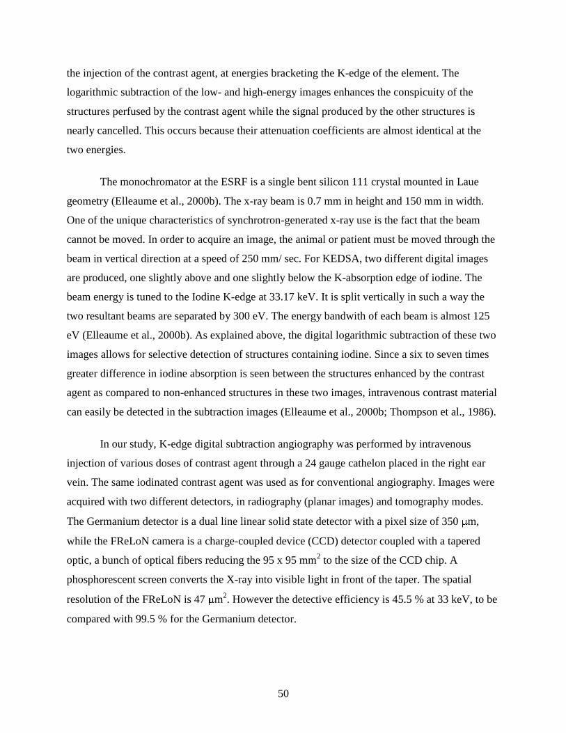
50
the injection of the contrast agent, at energies bracketing the K-edge of the element. The
logarithmic subtraction of the low- and high-energy images enhances the conspicuity of the
structures perfused by the contrast agent while the signal produced by the other structures is
nearly cancelled. This occurs because their attenuation coefficients are almost identical at the
two energies.
The monochromator at the ESRF is a single bent silicon 111 crystal mounted in Laue
geometry (Elleaume et al., 2000b). The x-ray beam is 0.7 mm in height and 150 mm in width.
One of the unique characteristics of synchrotron-generated x-ray use is the fact that the beam
cannot be moved. In order to acquire an image, the animal or patient must be moved through the
beam in vertical direction at a speed of 250 mm/ sec. For KEDSA, two different digital images
are produced, one slightly above and one slightly below the K-absorption edge of iodine. The
beam energy is tuned to the Iodine K-edge at 33.17 keV. It is split vertically in such a way the
two resultant beams are separated by 300 eV. The energy bandwith of each beam is almost 125
eV (Elleaume et al., 2000b). As explained above, the digital logarithmic subtraction of these two
images allows for selective detection of structures containing iodine. Since a six to seven times
greater difference in iodine absorption is seen between the structures enhanced by the contrast
agent as compared to non-enhanced structures in these two images, intravenous contrast material
can easily be detected in the subtraction images (Elleaume et al., 2000b; Thompson et al., 1986).
In our study, K-edge digital subtraction angiography was performed by intravenous
injection of various doses of contrast agent through a 24 gauge cathelon placed in the right ear
vein. The same iodinated contrast agent was used as for conventional angiography. Images were
acquired with two different detectors, in radiography (planar images) and tomography modes.
The Germanium detector is a dual line linear solid state detector with a pixel size of 350 m,
while the FReLoN camera is a charge-coupled device (CCD) detector coupled with a tapered
optic, a bunch of optical fibers reducing the 95 x 95 mm2 to the size of the CCD chip. A
phosphorescent screen converts the X-ray into visible light in front of the taper. The spatial
resolution of the FReLoN is 47 m2. However the detective efficiency is 45.5 % at 33 keV, to be
compared with 99.5 % for the Germanium detector.

51
The Germanium detector is 150 mm wide, X pitch = 350 µm. It consists of 2 horizontal
rows of 432 pixels. The physical height of 1 pixel is almost 10 mm. The distance between the 2
rows is just less 10 mm. To restore the Y dimension, the sample must be vertically moved in the
beam with vertical steps of 350 µm. The Y spatial resolution corresponds then to the vertical size
of the beam (700 µm). In tomography mode, the spatial resolution is defined by the 350 µm pixel
size and by the angular step. Usually the number of angular projections is the same as the
number of pixels. However, the final pixel size is always a square 350 µm x 350 µm.
4.2.2.1. Germanium detector, radiography mode (planar images)
Images were obtained after intravenous injection of Iomeprol® in doses ranging from 0.5
to 7.5 mL (0.5, 1.0, 2.0, 3.0, 4.0, 5 and 7.5 mL) over time periods ranging from 1 to 5 seconds,
using an automated injector pump controlled from outside the experimental hutch. The animal
was vertically moved through the beam to acquire the second dimension. The image resolution
was then 350 m in the horizontal plane and 350 m in the vertical plane.
4.2.2.2 Germanium detector, tomography mode
Three animals were submitted to tomographic imaging of the base of the brain,
visualizing the cerebral vasculature at the level of the Circle of Willis. Iomeprol 350® was
administered intravenously in doses ranging from 3 - 5 mL, with injection speeds ranging from
0.5 - 1 mL / second. Images were obtained from the start of injection for 20 seconds. The spatial
resolution was 350 x 350 μm2.
4.2.2.3. FReLoN camera, radiography mode (planar images)
On the 2000x2000 pixels of this camera, the spatial resolution was 47 x 47 μm2. Images
were acquired with the FReLoN camera in radiography mode in one animal only. Three mL of
Iomeprol® were injected intravenously at 0.7 mL / sec.
4.2.2.4. FReLoN camera, tomography
Two animals underwent tomographic image acquisition with the FReLoN camera.
Iomeprol®
was injected either at a rate of 0.7 mL / sec for 5, 7 or 10 seconds and at 15 mL / over
30 sec (5 mL / kg). The resolution was 47 x 47 μm2.
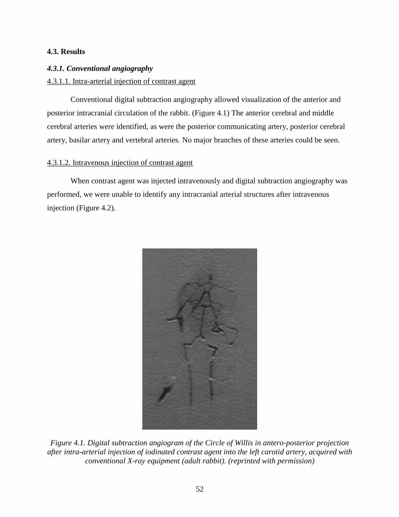
52
4.3. Results
4.3.1. Conventional angiography
4.3.1.1. Intra-arterial injection of contrast agent
Conventional digital subtraction angiography allowed visualization of the anterior and
posterior intracranial circulation of the rabbit. (Figure 4.1) The anterior cerebral and middle
cerebral arteries were identified, as were the posterior communicating artery, posterior cerebral
artery, basilar artery and vertebral arteries. No major branches of these arteries could be seen.
4.3.1.2. Intravenous injection of contrast agent
When contrast agent was injected intravenously and digital subtraction angiography was
performed, we were unable to identify any intracranial arterial structures after intravenous
injection (Figure 4.2).
Figure 4.1. Digital subtraction angiogram of the Circle of Willis in antero-posterior projection
after intra-arterial injection of iodinated contrast agent into the left carotid artery, acquired with
conventional X-ray equipment (adult rabbit). (reprinted with permission)
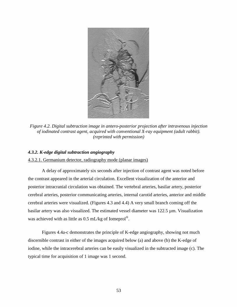
53
Figure 4.2. Digital subtraction image in antero-posterior projection after intravenous injection
of iodinated contrast agent, acquired with conventional X-ray equipment (adult rabbit).
(reprinted with permission)
4.3.2. K-edge digital subtraction angiography
4.3.2.1. Germanium detector, radiography mode (planar images)
A delay of approximately six seconds after injection of contrast agent was noted before
the contrast appeared in the arterial circulation. Excellent visualization of the anterior and
posterior intracranial circulation was obtained. The vertebral arteries, basilar artery, posterior
cerebral arteries, posterior communicating arteries, internal carotid arteries, anterior and middle
cerebral arteries were visualized. (Figures 4.3 and 4.4) A very small branch coming off the
basilar artery was also visualized. The estimated vessel diameter was 122.5 µm. Visualization
was achieved with as little as 0.5 mL/kg of Iomeprol®.
Figures 4.4a-c demonstrates the principle of K-edge angiography, showing not much
discernible contrast in either of the images acquired below (a) and above (b) the K-edge of
iodine, while the intracerebral arteries can be easily visualized in the subtracted image (c). The
typical time for acquisition of 1 image was 1 second.

54
Figure 4.3. Image of intracerebral arteries acquired in radiography mode with the germanium
detector in antero-posterior projection, using synchrotron K-edge digital subtraction
angiography. (a): early filling phase (b): late filling phase. (reprinted with permission)

55
Figure 4.4. Images acquired below (a) and above (b) the K-edge of iodine, both without easily
discernible contrast in the cerebral arteries. The subtracted image (c), however, shows very
good contrast in the cerebral arteries. (reprinted with permission)
4.3.2.2. FReLoN camera, radiography mode (planar images)
The images shown in Figure 4.5 were acquired with the FReLoN camera in angiography
mode. Acquisition time per image was 10 s.
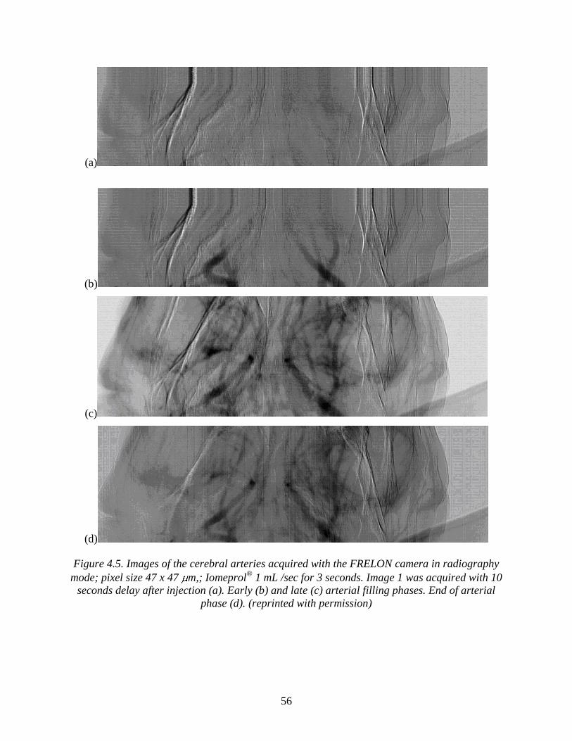
56
(a)
(b)
(c)
(d)
Figure 4.5. Images of the cerebral arteries acquired with the FRELON camera in radiography
mode; pixel size 47 x 47 m,; Iomeprol®
1 mL /sec for 3 seconds. Image 1 was acquired with 10
seconds delay after injection (a). Early (b) and late (c) arterial filling phases. End of arterial
phase (d). (reprinted with permission)
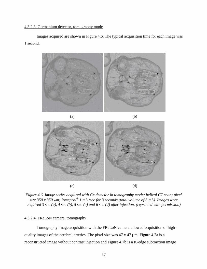
57
4.3.2.3. Germanium detector, tomography mode
Images acquired are shown in Figure 4.6. The typical acquisition time for each image was
1 second.
(a) (b)
(c) (d)
Figure 4.6. Image series acquired with Ge detector in tomography mode; helical CT scan; pixel
size 350 x 350 m; Iomeprol®
1 mL /sec for 3 seconds (total volume of 3 mL). Images were
acquired 3 sec (a), 4 sec (b), 5 sec (c) and 6 sec (d) after injection. (reprinted with permission)
4.3.2.4. FReLoN camera, tomography
Tomography image acquisition with the FReLoN camera allowed acquisition of high-
quality images of the cerebral arteries. The pixel size was 47 x 47 m. Figure 4.7a is a
reconstructed image without contrast injection and Figure 4.7b is a K-edge subtraction image
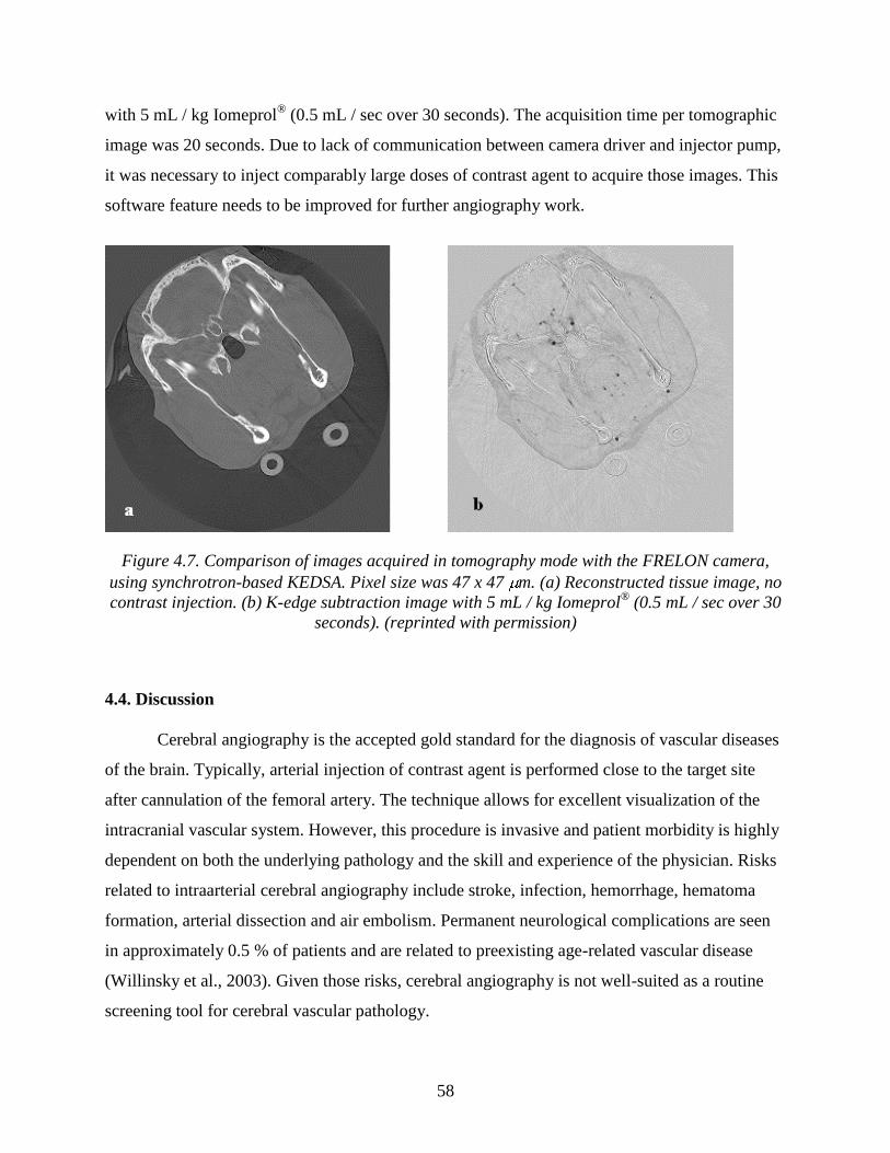
58
with 5 mL / kg Iomeprol®
(0.5 mL / sec over 30 seconds). The acquisition time per tomographic
image was 20 seconds. Due to lack of communication between camera driver and injector pump,
it was necessary to inject comparably large doses of contrast agent to acquire those images. This
software feature needs to be improved for further angiography work.
Figure 4.7. Comparison of images acquired in tomography mode with the FRELON camera,
using synchrotron-based KEDSA. Pixel size was 47 x 47 m. (a) Reconstructed tissue image, no
contrast injection. (b) K-edge subtraction image with 5 mL / kg Iomeprol®
(0.5 mL / sec over 30
seconds). (reprinted with permission)
4.4. Discussion
Cerebral angiography is the accepted gold standard for the diagnosis of vascular diseases
of the brain. Typically, arterial injection of contrast agent is performed close to the target site
after cannulation of the femoral artery. The technique allows for excellent visualization of the
intracranial vascular system. However, this procedure is invasive and patient morbidity is highly
dependent on both the underlying pathology and the skill and experience of the physician. Risks
related to intraarterial cerebral angiography include stroke, infection, hemorrhage, hematoma
formation, arterial dissection and air embolism. Permanent neurological complications are seen
in approximately 0.5 % of patients and are related to preexisting age-related vascular disease
(Willinsky et al., 2003). Given those risks, cerebral angiography is not well-suited as a routine
screening tool for cerebral vascular pathology.

59
Newer imaging modalities such as magnetic resonance angiography (MRA) and
computerized tomographic angiography (CTA) have been developed and provide excellent
visualization of the intracranial vasculature. For both CTA and MRA, the contrast agent can be
injected intravenously, thereby eliminating the risk inherent in arterial catheterization. However,
MRA and CTA do not allow for dynamic imaging like conventional arterial angiography. With
the latter, a substantial amount of information regarding the flow dynamics of the intracranial
circulation can be obtained during the arterial and venous phases of the contrast injection. This is
particularly important in the study of intracranial aneurysms, arteriovascular malformations and
arterial dissection of the brain where treatment planning is highly depended on information
obtained through those dynamic images. Therefore, we believe that the development of
intravenous cerebral angiography would significantly benefit patients with central nervous
system vascular pathology by providing a safe, dynamic and high-resolution system.
The use of an intravenous cerebral DSA technique may have the most potential in animal
research. We believe that KEDSA can be applied easily to small animal models. Along with
rabbits, we believe that even smaller animals such as rats and mice can be imaged. The use of
small animals is advantageous because it reduces cost, has less ethical issues and requires less
specialized animal handling facilities.
Within the last decade, several synchrotron laboratories have developed techniques to
perform coronary angiography using monochromatic synchrotron radiation (Dill et al., 2000;
Dix, 1995; Dix et al., 1989, 2003; Elleaume et al., 2000b; Estève et al., 2002a,b; Hamm et al.,
1996; Ohtsuka et al., 1999; Rubenstein et al., 1985, 1986; Thomlinson et al., 1991, 2000;
Thompson et al., 1986; Ventura et al., 2001). At some of these centers, human clinical studies
have been performed which have shown that the use of KEDSA is both safe and efficacious for
patients with coronary artery disease.
One of the facilities with extensive experience in intravenous synchrotron coronary
angiography is the European Synchrotron Radiation Facility (ESRF) in Grenoble, France. A
reliable safety system has been developed to protect both patients and experimentalists from
radiation overexposure (Elleaume et al., 2000a). During the patient studies at the ESRF, the x-ray
dose was monitored during the entire experiment (Elleaume et al., 2000a). The x-ray dose was 5
60
mGy/image. The total examination consisted in 6 images, providing a total dose of 30 mGy,
which is small compared to gold standard coronary angiography. Thus, the x-ray exposure in our
animal model was within the acceptable range for image acquisition with both germanium
detector and FReLoN camera. The tomographic image acquisition mode, on the other hand,
would pose a problem with both detectors. With acquisition times of 10 sec (germanium
detector) and 20 sec (FReLoN camera) per image, we would exceed the recommended X-ray
exposure dose even if only small series of images are acquired. Thus, before the tomography
mode could be used for image acquisition in human patients, the technical prerequisites would
need to be improved considerably.
In the studies of synchrotron coronary angiography performed at the ESRF, intravenous
injection of contrast material was obtained with a bolus injection via a central venous catheter.
Although these catheters are generally considered safe, a greater morbidity exists with central
intravenous line placement than with peripheral large bore intravenous access. Our study
demonstrated that it is possible to achieve an acceptable image quality even after using a
peripheral intravenous access.
Estève et al. have also studied gadolinium as a possible contrast agent for coronary
angiography (Estève et al., 2002a). This suggests a potential for this safer although significantly
more expensive contrast material for use in patients with iodine allergy if cerebral angiography is
required. Other studies, testing synchrotron-based intraarterial angiography in organs other than
the CNS, have shown the research potential of this technique in animal models (Tanaka et al.,
1999a,b).
KEDSA relies on synchrotron-based x-ray sources. The technique cannot be done outside
of a synchrotron. These sources are not widely available and this significantly impacts its future
widespread use for human imaging and animal experimentation.
There were artifacts noted in our study. They did not affect image interpretation but could
not be completely eliminated. On the planar images, horizontal artifacts come from beam
intensity modulations. This modulation is mainly due to monochromator vibrations. During CT,
61
circular artifacts come from detector imperfections that are not always well corrected by the
incident beam calibration.
Based on the results from our own study and existing experience collected elsewhere,
there is a significant potential for intravenous synchrotron-based angiographic imaging. The new
diagnostic technique could be applied safely to selected patients with suspected cerebral vascular
pathology. KEDSA could also be applied to the study of stroke, vasospasm and other intracranial
pathologies in animal models.
4.5. Conclusions
We have shown, with two different detector systems, that intravenous cerebral
angiography is feasible when using synchrotron based K-edge digital subtraction angiography in
a small animal model. We were able to obtain dynamic, high resolution images of the
intracranial circulation. Further work is required to assess future applications in human patients
and to assess the suitability of this technique for follow-up studies in patients after neurosurgical
and endovascular intervention. Although, we do not believe that synchrotron-based angiography
will replace conventional imaging techniques, indications for the use of synchrotron-based
KEDSA could include cases that are considered difficult to diagnose with conventional X-ray
equipment and animal studies.
4.6. Acknowledgements
We would like to thank Mr. Dominique Dallery from the animal care facility at ID 17,
ESRF, Grenoble, for his expert help in animal care and setting up our experiments at the
beamline. We also thank Stephanie Corde, PhD, Jean-Francois Le Bas, MD, PhD and Michel
Renier PhD for their assistance in the coordination of the project. This project has been funded
by the Saskatchewan Synchrotron Institute (SSI), the Department of Surgery at RUH, the
University of Saskatchewan, Royal University Hospital Innovation Fund, and by the grant of
beamtime at the European Synchrotron Radiation Facility (ESRF). Michael Kelly, MD held the
American Association of Neurological Surgeons, Depuy/Neurosurgery Research and Education
Foundation (NREF) fellowship during the study period.
62
The authors acknowledge Verl Sabourin from the Department of Surgery and Jan Jaspar
from the Vice President of Finances office at the University of Saskatchewan for their assistance
in arranging the financial backup for our research.
The authors also thank Beth Hoyte from Stanford University for her assistance with the
preparation of the figures.
4.7. References
Dill T, Job H, Dix WR, Ventura R, Kupper W, Hamm CW and Meinertz T: [Intravenous
coronary angiography with synchrotron radiation.] Z. Kardiol 89 Suppl 1:27-33, 2000.
Dix WR: Intravenous coronary angiography with synchrotron radiation. Prog Biophys Mol Biol
63: 159-91, 1995.
Dix WR, Engelke K, Heuer J, Graeff W, Kupper W, Lohmann M, Makin I, Mochel T and
Reumann R: [Noninvasive coronary angiography with synchrotron irradiation.] Biomed
Tech (Berl) 34 Suppl 79-80, 1989.
Dix WR, Kupper W, Dill T, Hamm CW, Job H, Lohmann M, Reime B and Ventura R:
Comparison of intravenous coronary angiography using synchrotron radiation with
selective coronary angiography. J Synchrotron Radiat 10 219-27, 2003.
Elleaume H et al: In vivo K-edge imaging with synchrotron radiation. Cell. Mol. Biol. (Noisy-le-
grand) 46:1065-75, 2000a
Elleaume H et al: First human transvenous coronary angiography at the European Synchrotron
Radiation Facility. Phys Med Biol 45:L39-43, 2000b.
Estève F et al: Coronary angiography with synchrotron X-ray source on pigs after iodine or
gadolinium intravenous injection. Acad Radiol 9 Suppl 1:S92-7, 2002a.
Estève F, Corde S, Elleaume H, Adam JF, Joubert A, Charvet AM, Biston MC, Balosso J and Le
Bas JF: Enhanced radio sensitivity with iodinated contrast agents using monochromatic
synchrotron X-rays on human cancerous cells Acad Radiol 9 Suppl 2:S540-3, 2002b.
Hamm CW et al: Intravenous coronary angiography with dichromography using synchrotron
radiation. Herz 21:127-31, 1996.
Mori H et al: Synchrotron microangiography reveals configurational changes and to-and-fro flow
in intramyocardial vessels. Am J Physiol 276: H429-37, 1999.

63
Ohtsuka S, Sugishita Y, Takeda T, Itai Y, Tada J, Hyodo K and Ando M: Dynamic intravenous
coronary angiography using 2D monochromatic synchrotron radiation Br J Radiol
72:24-8, 1999.
Rubenstein E, Brown GS, Harrison DC, Hofstadter R, Hughes EB, Kernoff RS, Otis JN,
Thompson AC and Zeman HD: Synchrotron radiation for transvenous coronary
angiography. Trans Am Clin Climatol Assoc 97:27-31, 1985.
Rubenstein E et al: Transvenous coronary angiography in humans using synchrotron radiation.
Proc Natl Acad Sci USA 83: 9724-8, 1986.
Suortti P and Thomlinson W: Medical applications of synchrotron radiation. Phys Med Biol
48:R1-35, 2003.
Tanaka A et al: Branching patterns of intramural coronary vessels determined by
microangiography using synchrotron radiation. Am J Physiol 276: H2262-7, 1999a.
Tanaka E, Tanaka A, Sekka T, Shinozaki Y, Hyodo K, Umetani K and Mori H: Digitized
cerebral synchrotron radiation angiography: quantitative evaluation of the canine circle of
Willis and its large and small branches. Am J Neuroradiol 20:801-6, 1999b.
Thomlinson W et al: Venous synchrotron coronary angiography. Lancet 337:360, 1991.
Thomlinson W et al: Research at the European Synchrotron Radiation Facility medical beamline.
Cell Mol Biol (Noisy-le-grand) 46:1053-63, 2000.
Thompson AC et al: Transvenous coronary angiography in dogs using synchrotron radiation. Int
J Card Imaging 2 53-8, 1986.
Ventura R, Dill T, Dix WR, Lohmann M, Job H, Kupper W, Fattori R, Nienaber CA, Hamm CW
and Meinertz T: Intravenous coronary angiography using synchrotron radiation: technical
description and preliminary results. Ital Heart J 2:306-11, 2001.
Willinsky RA, Taylor SM, TerBrugge K, Farb RI, Tomlinson G and Montanera W: Neurologic
complications of cerebral angiography: prospective analysis of 2,899 procedures and
review of the literature. Radiology 227:522-8, 2003.
64
CHAPTER 5.
RAPIC SCANNING X-RAY FLUORESCENCE IMAGING OF MAGNETICALLY LABELED
STEM CELLS IN A RAT STROKE MODEL, A PILOT STUDY
Adapted from
Kelly ME, Peeling L, Nichol H, Guzman R. For submission to the Canadian Journal of
Neurological Sciences
5.1. Introduction
Stroke is the leading cause of disability and number three cause of death in western
society. Current treatment modalities deal with prevention and management of acute stroke (The
NINDS-PA Stroke Study Group, 1995). Stem cell transplantation has the potential to assist with
neuroregeneration in stroke survivors. There have been three clinical trials examining stem cell
implantation in human stroke patients (Kondziolka et al., 2000, 2004, 2005; Nelson et al., 2002;
Savitz et al., 2005). Because of the complexity of human trials, animal models must first answer
the critical questions regarding stem cell implantation. The type of stem cell, location of
transplantation and timing of transplantation are critical to issues to ensure experimental success
(Guzman et al., 2007; Kelly et al., 2004; Modo et al., 2002). Guzman et al. (2007) studied the
utility of magnetic resonance imaging (MRI) to track implanted human stem cells in a rat stroke
model. In this study, they labeled the stem cells with superparamagnetic iron oxide (SPIO)
nanocomposites and studied migration of the stem cells both in vivo and ex vivo. Guzman et al.
(2007) showed that the SPIO concentration decreased by 50% every 3 days and that it is possible
to detect the stem cells for up to 6 cell divisions using MRI. However, MRI does have a
threshold that limits the detection of the SPIO labeled stem cells. The development of additional
advanced medical imaging techniques is important to better understand stem cell migration after
implantation.
65
The technique of X-ray fluorescence spectroscopic mapping is well established. An X-ray
fluorescence microprobe has been successfully employed to map metals in small areas of brain tissue
sections at high resolution but the time required to map large areas of the brain with a microprobe
is prohibitive. This limitation has recently been overcome by using Synchrotron-based rapid-
scanning X-ray fluorescence mapping (RS-XRF) (Gh Popescu et al., 2009; Linkous et al., 2008;
Miller et al., 2006). This is a new method which, like XRF microprobe, can simultaneously map
multiple metals but now rapidly enough to be useful in mapping whole brain slices.
In this study, SPIO labeled stem cells were tracked in a rat distal middle cerebral artery
model (dMCAO) using RS-XRF. Comparison was made between spin echo and gradient echo MR
sequences, histology and the RS-XRF to validate the location of SPIO within the neural stem cells.
5.2. Methods
The methods used for stem cell preparation, implantation, dMCAO, MRI imaging and
histology are previously reported by the senior author and are summarized below in the methods (Gh
Popescu et al., 2009).
5.2.1. Stem cell preparation
The stem cells were prepared in a standard fashion previously published by Guzman et
al.(2007). In summary, Human CNS Stem Cells Derived Neurosphere Cells (hCNS-SCns)
(StemCells, Inc., Palo Alto, CA) were isolated by flow cytometry from fetal brain tissue (16–20 wk).
hCNS-SCns cells were plated at 105 cells per mL in human neurosphere culture media (X-VIVO 15
medium; BioWhittaker, Walkersville, MD), N-2 supplement (GIBCO, Carlsbad, CA), and 0.2 mg/mL
heparin supplemented with basic fibroblast growth factor (20 ng/mL), EGF (20 ng/mL), and leukemia
inhibitory factor (10 ng/mL). On the day of transplantation, cells were prepared at a density of 1 x 10⁵
cells per µl. SPIO (Feridex IV, Berlex Laboratories, Wayne, NY, USA) and protamine sulfate
(American Pharmaceuticals Parter, Schaumburg, IL, USA) (5 µg/2.5 µg/mL) are incubated for 30 min
at 37˚C in culture medium before adding to the neural stem cells for 24 hours.
66
5.2.2. dMCAO method
dMCAO was performed in 15 adult male Sprague - Dawley rats. Anesthesia was achieved
with 1.5-2% Isoflurane in oxygen with a flow rate of 1.5 liter / min. The right lateral head of the
animals was shaved and disinfected with chlorhexidine and 70% alcohol. Animals were pre-
medicated with a subcutaneous injection of 0.05mg/kg Buprenorphine and received tapered doses in
12-hr intervals for 3 days. Using microscope magnification, the left common carotid artery is
temporarily occluded for 1 hour. The distal middle cerebral artery is then exposed, cauterized and cut
just above the rhinal fissure (Guzman et al. (2007)).
5.2.3. Stereotactic stem cell transplantation, histology and imaging
Labeled neural stem cells (3 x 10⁵ cells in three deposits) were stereotactically
transplanted into the striatum 7 days after stroke using a micropump. At 5 weeks, 2 control
animals and 2 transplanted animals were transcardially perfused. Ex vivo high-resolution MRI
was performed using a 4.7 Tesla animal scanner system (Varian, Palo Alto, CA) at 5 weeks on
the whole brain. Ex vivo imaging utilized spin echo T2 weighted MR imaging. After acquisition
of ex vivo whole brain MR images, specimens were sectioned to a thickness of 500 µm, mounted on
plastic coverslips and covered with 2 mil metal-free polypropylene. These specimens were then
mounted vertically and scanned with the RS-XFS probe. One mm sections were imaged by high
resolution RS-XRF in the same anatomical orientation using the standard technique described by
Gh Popescu et al. (2009). Side by side comparison was used to correlate the findings.
5.3. Results
5.3.1. MRI
MRI using T2 weighted spin echo sequences revealed positive signal at 5 weeks along the
periphery of the rat cortex on the side of the dMCAO. (Figure 1A) This represents migration of the
stem cells from the site of implantation to the region of infarction and has been previously reported by
the senior author (Guzman et al., 2007). Control imaging (animals without stem cell implantation) did
not reveal any signal change.
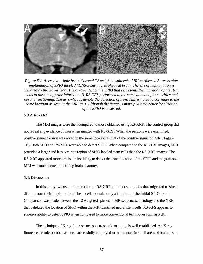
67
Figure 5.1. A. ex vivo whole brain Coronal T2 weighted spin echo MRI performed 5 weeks after
implantation of SPIO labeled hCNS-SCns in a stroked rat brain. The site of implantation is
denoted by the arrowhead. The arrows depict the SPIO that represents the migration of the stem
cells to the site of prior infarction. B. RS-XFS performed in the same animal after sacrifice and
coronal sectioning. The arrowheads denote the detection of iron. This is noted to correlate to the
same location as seen in the MRI in A. Although the image is more pixilated better localization
of the SPIO is observed.
5.3.2. RS-XRF
The MRI images were then compared to those obtained using RS-XRF. The control group did
not reveal any evidence of iron when imaged with RS-XRF. When the sections were examined,
positive signal for iron was noted in the same location as that of the positive signal on MRI (Figure
1B). Both MRI and RS-XRF were able to detect SPIO. When compared to the RS-XRF images, MRI
provided a larger and less accurate region of SPIO labeled stem cells than the RS-XRF images. The
RS-XRF appeared more precise in its ability to detect the exact location of the SPIO and the graft size.
MRI was much better at defining brain anatomy.
5.4. Discussion
In this study, we used high resolution RS-XRF to detect stem cells that migrated to sites
distant from their implantation. These cells contain only a fraction of the initial SPIO load.
Comparison was made between the T2 weighted spin-echo MR sequences, histology and the XRF
that validated the location of SPIO within the MR-identified neural stem cells. RS-XFS appears to
superior ability to detect SPIO when compared to more conventional techniques such as MRI.
The technique of X-ray fluorescence spectroscopic mapping is well established. An X-ray
fluorescence microprobe has been successfully employed to map metals in small areas of brain tissue
68
sections at high resolution but the time required to map large areas of the brain with a microprobe is
prohibitive. This limitation has recently been overcome by using synchrotron-based RS-XRF
mapping. This is a new method that, like XRF microprobe, can simultaneously map multiple metals in
whole brain slices (Popescu et al., 2009).
MRI has several limitations in the detection of implanted stem cells when compared to RS-
XRF: 1) detection of decreased SPIO concentrations with cell division and migration 2) quantification
of graft size 3) reliance on SPIO for cell detection using MRI.
5.4.1. Detection of decreased SPIO concentrations with cell division and migration
Guzman et al. (2007) found that the relative concentration of SPIO decreases by 50% every
three days. A previous report by Heyn et al. (2005) estimated that MRI could detect as little as 1.4-3.0
pg of iron per cell. Although detection of single cells containing iron has been reported (Shapiro et al.,
2006), Guzman et al. (2007) estimated that their 4.7 Tesla MRI had a detection limit of 1000 highly
concentrated cells. RS-XRF was readily able to detect the concentrations of SPIO seen on MRI. We
feel that this technique can likely detect much smaller concentrations of metals in the pg range.
As the cells migrate after implantation, the concentration is significantly reduced. This further
reduces the ability to detect these cells using conventional techniques. Also, death of transplanted cells
further reduces the concentration of cells available for detection. RS-XRF has superior resolution in
the range of 50 µm. Also, it is possible to perform RS-XRF with a microprobe. This probe has a
resolution of 5 µm which will allow further improvement in the technique to detect very small
concentrations of iron.
5.4.2. Quantification of graft size
Because of the superior resolution of RS-XRF, it is possible to better quantify the size of the
stem cell graft. This was an issue in the paper by Guzman et al. (2007). Early after transplantation, the
intracellular SPIO caused susceptibility artifact that significantly overestimated graft size. This was
especially present on the gradient echo sequences and they found the T2 spin echo weighted images to
be more accurate. However, at later time points, it became difficult to detect the SPIO using T2
weighted sequences and they relied on gradient echo sequences. Gradient echo sequences likely do
not provide an overly accurate way to quantify the cell graft.
69
RS-XRF does not have the artifact of gradient echo MRI. We believe that accurate
determination of the graft size can be made and this is a significant strength of RS-XRF over MRI.
5.4.3. Reliance on SPIO for cell detection using MRI
It has been previously shown that SPIO can inhibit mesenchymal stem cells from
differentiating into chondrocytes (Kosura et al., 2004). However, Guzman et al. (2007) did not find
any difference in cell viability for SPIO labeled neural stem cells versus unlabeled. They also did not
find a statistical difference in the differentiation potential between labeled and unlabeled cells. Spin
echo and gradient echo sequences were used to detect intracellular iron in the form of SPIO. Other
metals cannot be as accurately detected with MRI. In addition to the detection of iron, RS-XRF allows
for the detection of multiple metals such as gold, calcium, zinc, iodine and copper. Therefore, the
potential exists to utilize this technique to study cell migration using other metals such as gold to label
cells. The effects of SPIO on the stem cells appear to be small but are still likely more than that of a
more inert element such as gold which can be readily detected using RS-XRF.
5.4.4. Limitations of current study
This was an initial pilot study to validate the technique of RS-XRF to detect implanted stem
cells with SPIO and compare to T2 weighted MRI. Although we were able to clearly visualize the iron
particles, we did not study the minimal concentration we could detect using this technique. Further
study is needed to validate RS-XRF as being superior to MRI in both its resolution and detection of
iron. We did not compare spin echo MRI to RS-XRF. Also, the current study did not analyze a
significant number of specimens to allow for any statistical analysis.
This study was performed on ex vivo specimens. Guzman et al. (2007) used in vivo MRI to
detect stem cells. This is a significant limitation to RS-XRF. We feel that it will not eliminate the use
of MRI to monitor stem cell implantation but instead help to validate and quantitate the MRI findings.
5.5. Conclusion
RS-XRF allows for accurate ex vivo detection of SPIO labeled implanted human neural stem
cells. RS-XRF may allow for more accurate quantification of the graft size and better detection of low

70
concentrations of the cells, especially at later time points. Further work is required to better establish
the technique and its overall utility.
5.6. Acknowledgements
This work was supported by a Canadian Health Research Programs (CHRP) grant to H.N.
that is funded by the Natural Sciences and Engineering Research Council of Canada (NSERC)
and the Canadian Institutes of Health Research (CIHR). Portions of this research were carried
out at the Stanford Synchrotron Radiation Laboratory, a national user facility operated by
Stanford University on behalf of the U.S. Department of Energy, Office of Basic Energy
Sciences. The SSRL Structural Molecular Biology Program is supported by the Department of
Energy, Office of Biological and Environmental Research and by the National Institutes of
Health, National Center for Research Resources, Biomedical Technology Program.
5.7. References
The National Institute of Neurological Disorders and Stroke rt-PA Stroke Study Group: Tissue
plasminogen activator for acute ischemic stroke. N Engl J Med 333:1581-1587, 1995.
Gh Popescu BF, George MJ, Bergmann U, Garachtchenko AV, Kelly ME, McCrea RP, Luning
K, Devon RM, George GN, Hanson AD, Harder SM, Chapman LD, Pickering IJ, Nichol
H: Mapping metals in Parkinson's and normal brain using rapid-scanning x-ray
fluorescence. Phys Med Biol 54:651-663, 2009.
Guzman R, Uchida N, Bliss TM, He D, Christopherson KK, Stellwagen D, Capela A, Greve J,
Malenka RC, Moseley ME, Palmer TD, Steinberg GK: Long-term monitoring of
transplanted human neural stem cells in developmental and pathological contexts with
MRI. Proc Natl Acad Sci USA 104:10211-10216, 2007.
Heyn C, Bowen CV, Rutt BK, Foster PJ: Detection threshold of single SPIO-labeled cells with
FIESTA. Magn Reson Med 53:312-320, 2005.
71
Kelly S, Bliss TM, Shah AK, Sun GH, Ma M, Foo WC, Masel J, Yenari MA, Weissman IL,
Uchida N, Palmer T, Steinberg GK: Transplanted human fetal neural stem cells survive,
migrate, and differentiate in ischemic rat cerebral cortex. Proc Natl Acad Sci USA
101:11839-11844, 2004.
Kondziolka D, Steinberg GK, Cullen SB, McGrogan M: Evaluation of surgical techniques for
neuronal cell transplantation used in patients with stroke. Cell Transplant 13:749-754,
2004.
Kondziolka D, Steinberg GK, Wechsler L, Meltzer CC, Elder E, Gebel J, Decesare S, Jovin T,
Zafonte R, Lebowitz J, Flickinger JC, Tong D, Marks MP, Jamieson C, Luu D, Bell-
Stephens T, Teraoka J: Neurotransplantation for patients with subcortical motor stroke: a
phase 2 randomized trial. J Neurosurg 103:38-45, 2005.
Kondziolka D, Wechsler L, Goldstein S, Meltzer C, Thulborn KR, Gebel J, Jannetta P, DeCesare
S, Elder EM, McGrogan M, Reitman MA, Bynum L: Transplantation of cultured human
neuronal cells for patients with stroke. Neurology 55:565-569, 2000.
Kostura L, Kraitchman DL, Mackay AM, Pittenger MF, Bulte JW: Feridex labeling of
mesenchymal stem cells inhibits chondrogenesis but not adipogenesis or osteogenesis.
NMR Biomed 17:513-517, 2004.
Linkous DH, Flinn JM, Koh JY, Lanzirotti A, Bertsch PM, Jones BF, Giblin LJ, Frederickson
CJ: Evidence that the ZNT3 protein controls the total amount of elemental zinc in
synaptic vesicles. J Histochem Cytochem 56:3-6, 2008.
Miller LM, Wang Q, Telivala TP, Smith RJ, Lanzirotti A, Miklossy J: Synchrotron-based
infrared and X-ray imaging shows focalized accumulation of Cu and Zn co-localized with
beta-amyloid deposits in Alzheimer's disease. J Struct Biol 155:30-37, 2006.
Modo M, Stroemer RP, Tang E, Patel S, Hodges H: Effects of implantation site of stem cell
grafts on behavioral recovery from stroke damage. Stroke 33:2270-2278, 2002.
Nelson PT, Kondziolka D, Wechsler L, Goldstein S, Gebel J, DeCesare S, Elder EM, Zhang PJ,
Jacobs A, McGrogan M, Lee VM, Trojanowski JQ: Clonal human (hNT) neuron grafts
for stroke therapy: neuropathology in a patient 27 months after implantation. Am J
Pathol 160:1201-1206, 2002.

72
Savitz SI, Dinsmore J, Wu J, Henderson GV, Stieg P, Caplan LR: Neurotransplantation of fetal
porcine cells in patients with basal ganglia infarcts: a preliminary safety and feasibility
study. Cerebrovasc Dis 20:101-107, 2005.
Shapiro EM, Sharer K, Skrtic S, Koretsky AP: In vivo detection of single cells by MRI. Magn
Reson Med 55:242-249, 2006.
73
CHAPTER 6.
DISCUSSION
6.1. Overview
I entered my PhD program to become a well trained physician-scientist. I realized that
my position as a clinical neurosurgery trainee could enhance the experimental design and that the
focus of my research should be the application of this technique towards clinical problems. The
research presented in this thesis is unique in the field of neurosurgery. My objective was to
discover novel biomedical applications of synchrotron imaging and apply them to solve
problems in neurosurgery. In some ways, biomedical imaging using synchrotron is an extremely
precise and expensive tool looking for a use, and therefore a secondary goal of my research was
to identify other biomedical applications for synchrotron imaging.
One of the most important aspects I learned during the many experimental sessions,
extensive data analysis, and meetings during my PhD research was that of collaboration. As a
fellowship trained neurosurgeon, I can bring many unique ideas and direction to experimental
implementation and design. However, complex synchrotron based experiments cannot be
performed without excellent collaboration with basic scientists (physicists, anatomists, and cell
biologists).
The objective of this discussion is to not recite the discussions from Chapters 2-5, but to
bring all of the experiments together and show how they are connected.

74
6.2. Diffraction enhanced imaging of the spine
The initial experimental ideal was to attempt to image the rat spinal cord using DEI.
Experiments were performed at the National Synchrotron Light Source in 2003, with attempts
made to visualize the neuronal injury induced by a clip model for spinal cord injury.
Unfortunately, DEI was unable to image the spinal cords because of a complete lack of contrast,
likely related to the inability of the small rat spinal cord specimens (with associated dura mater)
to affect the X-rays. With no absorption or refraction of the photons, the spinal cords could not
be visualized.
However, when the actual vertebral columns were imaged with DEI, excellent anatomical
detail was observed. This became the very obvious direction towards which future experimental
designs could be directed. The initial work presented in Chapter 2 was novel because of the
excellent anatomical detail. As discussed in Chapter 2, the ability to observe suture material was
extremely interesting and established the utility of the technique for spine imaging in animal
models. We attempted to image whole animals and compare the images to separately explanted
spinal columns, and found some artifact and loss of contrast secondary to the overlying tissues
and hair. This is one of the major limitations of the DEI set up presented in this thesis.
Fortunately, this will be overcome with the completion of the biomedical beamline at the
Canadian Light Source at the University of Saskatchewan, which will be able to image live
animals.
6.3. Analyzer based imaging of spinal fusion in an animal model
With the results obtained in Chapter 2, the future direction of the experiments moved
towards establishing an experimental design that would study a particular problem in
neurosurgery. Given the excellent resolution and contrast, the idea to image spinal fusion was
formulated. As discussed in Chapter 3, the ability to identify the presence of spinal fusion in
small animal models is difficult and often not very analogous to human spinal fusion due to the
inability to detect small amounts of bone graft material and properly assess its incorporation into
the existing bone. Existing small animal models require large amounts of bone graft material to
be placed in order to be visualized. We were able to show that small amounts of bone graft could
be 1) detected and 2) incorporated into the existing bone identified. However, the major
75
limitation of this experiment was again related to the inability to image live animals. This was
overcome by using numerous animals and sacrificing them at set time points. In the future,
imaging of live animals will be possible and obviate the need to sacrifice animals at set time
points. In other words, the same animal can be followed for the duration of the experiment. This
reduces the number of animals required, which reduces financial and especially ethical issues.
The future direction of my PhD research was initially focused on expanding on the
information presented in Chapter 3. Several of my colleagues in radiology and orthopedic
surgery used this data to develop experiments analyzing growth plate injuries. However, a
change in my clinical neurosurgery interest, towards cerebrovascular and endovascular
neurosurgery, affected the future direction of my PhD research. At this point, I began exploring
fellowship opportunities in this particular subspecialty, which in turn led to a new research
direction.
6.4. K-edge digital subtraction angiography
I began to explore the potential applications of KEDSA to solve problems in
cerebrovascular and endovascular neurosurgery. This formulated the basis of the research
presented in Chapter 4. The research presented in Chapter 4 is unique; prior experiments had
been done using KEDSA but the work in Chapter 4 is novel in its application to cerebral
angiography. I also felt the ability to perform serial imaging in live animals was a major benefit
of the KEDSA experiments. A large multidisciplinary research group was involved in the
execution of these experiments, the results of which are presented in Chapter 4. From this work,
other experiments were born. The group looked at spinal and peripheral vascular imaging, and
conducted preliminary experiments to study a rabbit model of vasospasm. Additional KEDSA
experiments were performed on larger animals (pigs) to further validate the technique and
increase its applicability to human imaging.
The ability to image humans was always the objective of the KEDSA experiments. As
discussed in Chapter 4, KEDSA can be performed using intravenous contrast injection. This has
a substantially better safety profile than conventional intra-arterial cerebral angiography.
However, significant advances in computerized tomography and magnetic resonance
angiography occurred around the time of the experiments. Clinicians became, and continue to be,
76
more and more comfortable using CTA and MRA to study the cerebral vasculature. In many
ways, these important advances reduced the requirement to be able to perform intravenous
KEDSA in humans. At the conclusion of the research presented in Chapter 4, the future direction
of my PhD research was reevaluated.
6.5. Rapid scanning X-ray fluorescence
In my opinion, the research presented in Chapter 5 is the most exciting. One of my
collaborators and chairperson of my PhD committee from Saskatoon required access to human
brain samples for RS-XRF analysis at Stanford Synchrotron Radiation Laboratory. I was a fellow
in cerebrovascular surgery at Stanford at the time and was able to supply the samples. During
these initial RS-XRF experiments, very small amounts of iron and other metals could be readily
detected.
Also fortuitous was that during my fellowship training at Stanford University, I was
exposed to the basic science research of Dr. Raphael Guzman. Dr. Guzman and his collaborators
were studying the migration of stem cells after implantation in a stroke model. The analysis of
the migration was done using histology and MRI. As discussed in Chapter 5, the implanted cells
were labeled with SPIO. Based on my prior experience with RS-XRF and my exposure to the
stem cell migration experiments, the final experiment presented in this thesis was formulated.
Although the results presented are in Chapter 5 are preliminary, they are very important.
The ability of RS-XRF to detect stem cell migration is important as it provides a non-destructive
and simple way to detect migration patterns. As the technique continues to evolve, the ability to
detect a single SPIO labeled cell is becoming possible. This will allow for better determination of
migration patterns and the effects of various effectors on this migration. Future development of
the technique may allow for in vivo imaging but further work is needed to develop these
techniques.
The work presented in Chapter 5 is also important because it has formed the basis for my
future research. RS-XRF holds great promise to help with future stem cell experiments and
hopefully assist in establishing the ultimate goal—human stem cell therapy. This is the ultimate
future direction of my research.

77
6.6. Summary
This thesis reflects the evolution of my research, which has been influenced by my
preceptors, my neurosurgery career, and my results. This thesis does ―solve problems in
neurosurgery‖. I have also learned more than just the title of the thesis: I have a much better
understanding of how to use experimental imaging techniques. The synchrotron is not a device
that will replace existing techniques. It is a very powerful tool that is best used to enhance and
supplement other techniques.

78
CHAPTER 7.
CONCLUSIONS
1. Diffraction Enhanced Imaging is an excellent tool to study the boney anatomy of the spine.
2. Analyzer based imaging allows for excellent determination of bony fusion in an animal
model.
3. Intravenous K-edge digital subtraction angiography is able to readily visualize the cerebral
vasculature in an animal model.
4. Rapid scanning X-ray fluorescence mapping is able to identify migrating stem cells labeled
with superparamagnetic iron oxide nanocomposites.
5. Various biomedical applications of synchrotron radiation can be applied to a field such as
neurosurgery to help find solutions to clinical problems

79
CHAPTER 8.
IMPACT
The objective of the PhD research in this thesis was to develop biomedical applications of
synchrotron radiation imaging techniques related to the field of neurosurgery. I feel I have been
successful in achieving this goal. The synchrotron is a very powerful tool looking for
applications. The search for biomedical imaging applications and how they relate to various
problems in neurosurgery is what forms the basis and common link of this thesis. The work here
has formed an important foundation for many other publications that subsequently grew from
this research.
Collaboration is also an important impact of this research. During my training and PhD
research, I have worked with many brilliant researchers whose participation was critical to the
success of past work; these collaborative relationships continue to be important in the present and
for future work. This is reflected in my recent involvement as a co-investigator in two grants
awarded by CIHR, amounting to over $4.75 million, for biomedical applications and training in
synchrotron imaging techniques.
80
APPENDIX.
SIMULTANEOUS ACHIEVEMENTS DURING PhD
A.1. Completion of neurosurgery residency and certification by the Royal College of
Physicians and Surgeons in Neurosurgery
I began my PhD research in September of 2003, during the fourth year of my
neurosurgery training. During neurosurgery training, residents are allowed and encouraged to
perform basic science research. Because of the accommodations made by my neurosurgery
program directors, I was able to simultaneously undertake my neurosurgery residency and PhD
research. I completed my required 12 credits of classes during my residency and subsequently
began the research reported in this thesis. During the course of my residency, I was also able to
complete the qualifying and comprehensive exams for my PhD. In 2004, I was awarded the
American Association of Neurological Surgeons, Neurosurgery Research and Education
Foundation (NREF) DePuy Research Fellowship. This award for $40,000 was one of the main
funding sources for my PhD research. In June of 2005, I completed my residency and also
became certified by the Royal College of Physicians and Surgeons of Canada in Neurosurgery. It
was not easy to simultaneously complete my residency and conduct the majority of the PhD
research, and I owe a great deal of gratitude to those people who assisted me on along the way. I
have included many of these people in the Acknowledgements section.
A.2. Completion of three year fellowship training in cerebrovascular and endovascular
neurosurgery
I spent three years, from July 2005 to June 2008, in the United States learning advanced
techniques for the management of cerebrovascular disorders. I spent one year at Stanford
University Medical Center under the tutelage of Gary Steinberg, MD, PhD, Chairman of
Neurosurgery. I learned advanced surgical techniques for brain aneurysms, vascular

81
malformations, stroke, and skull base surgery. After my year in California, I moved to
Cleveland, Ohio, and began a two year fellowship in endovascular surgical neuroradiology,
cerebrovascular surgery, and radiosurgery. During this time, I continued to learn new techniques
to better care for patients with cerebrovascular disorders.
In July 2008, I began my present position as Assistant Professor in the Division of
Neurosurgery, Department of Surgery, at the University of Saskatchewan. During the last year, I
was able to establish a program for the management of patients with cerebrovascular disorders
using advanced surgical and endovascular neurosurgery techniques.
A.3. Other publications and presentations
I have been fortunate to be able to publish a significant number of scientific manuscripts
during my career. In addition to the three manuscripts presented in this thesis, I have published
43 papers in various scientific journals. Thirty of these papers have been during the last three
years. I believe my scientific productivity is due to the combination of my basic science and
clinical research. I have been fortunate to work with many excellent researchers who have
inspired me to become academically productive.
I have also presented 34 papers at scientific meetings and given 26 invited lectures. I
have recently been a co-investigator on two grants. I am a co-applicant on Training in Health
Research Using Synchrotron Techniques (THRUST), which was awarded a total of $165,000 in
the first year and $325,000 for the remaining five years from CIHR. Commitments from other
funding sources bring the total budget over 6 years to $2,358,200. I am also a co-investigator on
a CIHR Team in Synchrotron Imaging grant, which was recently awarded $2,395,000 over five
years starting September 2009.