Embed Size (px)
Citation preview

Freescale SemiconductorApplication Note
AN2968Rev. 1, 02/2012
Table of ContentsIntroduction . . . . . . . . . . . . . . . . . . . . . . . . . . . . . . . . . . . 1Function Set Overview . . . . . . . . . . . . . . . . . . . . . . . . . . 2
2.1 General Purpose Input/Output (GPIO) . . . . . . . . . . 32.2 AC Motor Control PWM Generator (PWMMAC with
PWMF) . . . . . . . . . . . . . . . . . . . . . . . . . . . . . . . . . . 32.3 Quadrature Decoder (QD, QDINDEX, QDHOME) . 42.4 Resolver Interface (RSLV). . . . . . . . . . . . . . . . . . . . 42.5 Analog Sensing for AC Motors (ASAC) . . . . . . . . . . 52.6 AC Induction Motor Volts per Hertz Control (ACIM-
VHZ) . . . . . . . . . . . . . . . . . . . . . . . . . . . . . . . . . . . . 52.7 Permanent Magnet Synchronous Motor Vector Con-
trol (PMSMVC) . . . . . . . . . . . . . . . . . . . . . . . . . . . . 52.8 AC Induction Motor Vector Control (ACIMVC) . . . . 62.9 Speed Controller (SC) . . . . . . . . . . . . . . . . . . . . . . . 62.10 Break Controller (BC) . . . . . . . . . . . . . . . . . . . . . . . 6Function Set Usage . . . . . . . . . . . . . . . . . . . . . . . . . . . . . 6
3.1 eTPU Function Source Code and Binary Image . . . 73.2 eTPU Function APIs . . . . . . . . . . . . . . . . . . . . . . . . 73.3 eTPU Application APIs . . . . . . . . . . . . . . . . . . . . . . 7Function Set Description . . . . . . . . . . . . . . . . . . . . . . . . 10
4.1 eTPU Function Interactions . . . . . . . . . . . . . . . . . . 104.2 eTPU Requests Generated to the CPU. . . . . . . . . 114.3 eTPU Timing and Engine Load . . . . . . . . . . . . . . . 13Summary and Conclusions . . . . . . . . . . . . . . . . . . . . . . 24Revision history . . . . . . . . . . . . . . . . . . . . . . . . . . . . . . . 24
Using the AC Motor Control eTPU Function Set (set4)Covers the MCF523x, MPC5500, MPC5600 and all eTPU-equipped Devicesby: Milan Brejl, Michal Princ
System Application Engineers, Roznov Czech System Center
1 IntroductionThe enhanced time processing unit (eTPU) is a programmable I/O controller with its own core and memory system, allowing it to perform complex timing and I/O management independently of the CPU. The eTPU module is a peripheral for new 32-bit devices on the industrial and automotive markets (currently, the ColdFire MCF523x and Power Architecture MPC5500 and MPC5600 families).
The eTPU features can be advantageously applied in various motor control applications. The eTPU module is capable of handling motor speed and position sensing, closed loop control of current, speed, and/or position, PWM modulation, etc.
The eTPU runs independently of the CPU, making the CPU available for high-level tasks. When the eTPU is utilized for time-critical motor control tasks, it becomes a motor control coprocessor.
Freescale Semiconductor provides a library of motor control eTPU functions. The library consists of eTPU functions, which serve as building blocks for various eTPU applications.
12
3
4
56
© Freescale Semiconductor, Inc., 2006, 2012. All rights reserved.

Function Set Overview
The library is divided in two function sets:
• DC motor control eTPU function set
• AC motor control eTPU function set
The DC motor control eTPU functions set includes eTPU functions dedicated to DC and brushless DC (BLDC) motor control applications. The AC motor control eTPU function set is dedicated to permanent magnet synchronous motors (PMSM) and AC induction motors (ACIM).
This application note is intended to provide a description of the AC motor control eTPU function set.
2 Function Set OverviewThe AC motor control eTPU function set includes the following motor control techniques:
• Generation of PWM signals
• Decoding of signals from a shaft encoder
• Calculation of rotor position using a resolver
• Speed control
• V/Hz control
• Torque (current) vector control
• DC-bus break control
A motor control drive which utilizes several of the listed techniques can be fully handled by the eTPU.
The AC motor control eTPU function set consists of 12 eTPU functions:
• GPIO - general purpose input/output
• PWMMAC - PWM master for AC motors
— PWMF - PWM full range
• QD - quadrature decoder
— QDHOME - quadrature decoder home
— QDINDEX - quadrature decoder index
• RSLV - resolver interface
• ASAC - analog sensing for AC motors
• ACIMVHZ - AC induction motor volts per hertz control
• PMSMVC - permanent magnet synchronous motor vector control
• ACIMVC - AC induction motor vector control
• SC - speed controller
• BC - break controller
The eTPU functions are configurable and adjustable using various parameters and options, giving the user the ability to customize these functions to their specific application.
Using the AC Motor Control eTPU Function Set (set4), Rev. 1
Freescale Semiconductor2

Function Set Overview
The following paragraphs briefly describe the purpose of each eTPU function in a motor control application.
2.1 General Purpose Input/Output (GPIO)This function originates from the general eTPU function set (set1), and is included in the AC motor control eTPU function set as well. It can be assigned to an eTPU channel that is not used by any other eTPU functions, in order to use the associated pin for general purposes.
In motor control applications on the MCF523x devices, the GPIO functions can be used to generate an interrupt on a fault. The fault signal, which is usually connected to the eTPU output disable input, can be also connected to the eTPU channel assigned a GPIO function. When the fault signal turns active, selected output channels are immediately disabled by the eTPU hardware. At the same time, the GPIO function generates an interrupt in order to notify the CPU about the fault occurrence.
2.2 AC Motor Control PWM Generator (PWMMAC with PWMF)
The generation of PWM signals for AC motor-control applications with eTPU is provided by two eTPU functions:
• PWM - master for AC motors (PWMMAC)
• PWM - full range (PWMF)
The PWM master for AC motors (PWMMAC) function calculates sine wave or space vector modulation resulting in PWM duty cycles, and updates up to three PWM phases. The phases are driven by the PWM full range (PWMF) function, which enables a full (0% to 100%) duty-cycle range.
The AC motor control PWM generator can generate one, two, or three PWM phases. Each phase may be represented by a single PWM channel or a complementary pair of PWM channels with dead-time. The output signal polarity is selectable, and both edge-aligned and center-aligned PWM are supported.
The PWMMAC function transforms input parameters into phase duty-cycles by modulation. The following modulations are provided by the PWMMAC function:
• Unsigned Voltage (VOLTAGE_UNSIGNED) - The input parameter is an applied motor voltage in the range (0,1). The voltage range (0,1) corresponds to the duty-cycle range (0%, 100%).
• Signed Voltage (VOLTAGE_SIGNED) - The input parameter is an applied motor voltage in the range (-1,1). The voltage range (-1,1) corresponds to the duty-cycle range (0%, 100%).
• No Modulation (NO) - No input parameters are transformed into phase duty-cycles. The phase duty-cycles must be provided.
• Standard Space Vector Modulation (SVM_STD) - The input parameters are orthogonal components of an applied motor voltage vector alpha and beta in the range (-1,1).
• Space Vector Modulation With O000 Nulls (SVM_U0N) - The input parameters are orthogonal components of an applied motor voltage vector alpha and beta in the range (-1,1).
Using the AC Motor Control eTPU Function Set (set4), Rev. 1
Freescale Semiconductor 3

Function Set Overview
• Space Vector Modulation With O111 Nulls (SVM_U7N) - The input parameters are orthogonal components of an applied motor voltage vector alpha and beta in the range (-1,1).
• Inverse Clark Transformation (ICT) - The input parameters are alpha and beta components of the stator reference voltage vector, both in the range (-1,1). The 3-phase duty cycles are calculated based on these inputs and using the Inverse Clark Transformation.
• Sine Table Modulation (SINE_TABLE) - The input parameters are the applied motor voltage vector amplitude and angle. The amplitude is in the range (0,1), and the angle is in the range (-1,1), corresponding to the (-180,180) degree range.
• User-Defined Table Modulation (USER_TABLE) - The input parameters are the amplitude and angle of an applied motor voltage vector. The amplitude is in the range (0,1), and the angle is in range (-1,1), corresponding to the (-180°,180°) degree range. Modulation is based on the first quadrant modulation table defined by the user. For example, the modulation table can be a sine wave with third harmonic injection in the (0°,90°) degree range.
For a full description of all features, refer to “Using the AC Motor Control PWM eTPU Functions,” AN2969.
2.3 Quadrature Decoder (QD, QDINDEX, QDHOME)The QD eTPU functions are intended to process signals generated by a shaft encoder in motion control systems. It uses two channels to decode a pair of out-of-phase encoder signals to produce a 24-bit, bi-directional position counter, together with directional information, for the CPU. A QD counts detected transitions and stores transition times, which can be used by the speed controller function for actual motion system speed calculation.
Additional input channels can be also processed. The index channel receives a pulse on each revolution. Based on the actual direction, a revolution counter is incremented or decremented on the index pulse. Furthermore, additional input channel can indicate a home position. When this position is reached, appropriate actions are taken (a reset of the position counter and the revolution counter).
For a full description of all features, refer to “Using the Quadrature Decoder (QD) eTPU Function,” AN2842.
2.4 Resolver Interface (RSLV)The RSLVeTPU function is intended to process signals from the resolver hardware (sampled by an AD converter and transferred to the eTPU data memory by a DMA transfer). The RSLV function is able to calculate the motor position and speed, using an Angle Tracking Observer Algorithm. The RSLV eTPU function can also be used to generate the resolver excitation signal.
For a full description of all features, refer to “Using the Resolver Interface eTPU Function,” AN3943.
Using the AC Motor Control eTPU Function Set (set4), Rev. 1
Freescale Semiconductor4
Function Set Overview
2.5 Analog Sensing for AC Motors (ASAC)The ASAC function is useful for preprocessing up to four analog values that are measured by an AD converter and transferred to the eTPU data memory by a DMA transfer. The ASAC function can trigger the AD converter, request the DMA transfer, and synchronize other eTPU functions.
For a full description of all features, refer to “Using the Analog Sensing for AC Motors (ASAC) eTPU Function,” AN2970.
2.6 AC Induction Motor Volts per Hertz Control (ACIMVHZ)The purpose of the ACIMVHZ function is to perform the simple V/Hz control of the AC induction motor. The ACIMVHZ calculates applied voltage vector components based on required speed (omega) and defined V/Hz ramp. The output applied voltage vector components can be either:
• amplitude & angle for sinusoidal modulation, or
• alpha & beta for space vector modulation
The ACIMVHZ function optionally enables passing the required speed through a speed ramp to slow down step changes of the input parameter.
For a full description of all features, refer to “Using the ACIM Volts per Hertz (ACIMVHZ) eTPU Function,” AN2971.
2.7 Permanent Magnet Synchronous Motor Vector Control (PMSMVC)
The purpose of the PMSMVC function is to perform the current control loop of a field-oriented (vector control) drive of a PMSM. The sequence of PMSMVC calculations consists of the following steps:
• Forward Clarke transformation
• Forward Park transformation (establishing the DQ coordinate system)
• D&Q current controllers calculation
• Decoupling and back-EMF feed forward
• Circle limitation
• Inverse Park transformation
• DC-bus ripple elimination
The PMSMVC calculates applied voltage vector components alpha and beta based on measured phase currents and required values of phase currents in 2-phase orthogonal rotating reference frame (D-Q). The PMSMVC function optionally enables to perform the limitation of calculated D and Q components of the stator voltages into the circle.
For a full description of all features, refer to “Using the PMSM Vector Control eTPU Function,” AN2972.
Using the AC Motor Control eTPU Function Set (set4), Rev. 1
Freescale Semiconductor 5

Function Set Usage
2.8 AC Induction Motor Vector Control (ACIMVC)The purpose of the ACIMVC function is to perform the current control loop of a field-oriented (vector control) drive of a ACIM. The sequence of ACIMVC calculations consists of the following steps:
• Forward Clarke transformation
• Rotor Flux Estimation
• DQ establishment (including calculation of sine, cos, omega_field, and Forward Park transformation)
• D&Q current controllers calculation
• Decoupling
• Circle limitation
• Inverse Park transformation
• DC-bus ripple elimination
The ACIMVC calculates applied voltage vector components alpha and beta based on measured phase currents and required values of phase currents in 2-phase orthogonal rotating reference frame (D-Q). The ACIMVC function optionally enables to perform the limitation of calculated D and Q components of the stator voltages into the circle.
For a full description of all features, refer to “Using the ACIM Vector Control eTPU Function,” AN2973.
2.9 Speed Controller (SC)The purpose of the SC function is to control another eTPU function’s input parameter. The SC function includes a PID controller algorithm. The controller calculates its output based on two inputs: a measured value and a desired value. The measured value—the actual motor speed—is calculated based on inputs provided by the Quadrature Decoder function. The desired value is an output of a speed ramp, whose input is a SC function parameter, and can be provided by the CPU or another eTPU function. In the AC motor-control eTPU function set, this function mostly provides the speed closed loop.
For a full description of all features, refer to “Using the Speed Controller (SC) eTPU Function,” AN2843.
2.10 Break Controller (BC)The BC function is useful for controlling the DC-bus break. The DC-bus break is required when a motor is driven not only in the motoring mode, but also in the generating mode. The DC-bus break switch can be controlled in an ON/OFF mode or a PWM mode.
For a full description of all features, refer to “Using the Break Controller (BC) eTPU Function,” AN2845.
3 Function Set UsageThe AC motor control eTPU function set release consists of the following items.
Using the AC Motor Control eTPU Function Set (set4), Rev. 1
Freescale Semiconductor6

Function Set Usage
3.1 eTPU Function Source Code and Binary ImageThe eTPU function source code and the compiled binary image are included in the following package, which is available on the Freescale website (http://www.freescale.com/etpu):
• AN2968SW - AC motor control eTPU function set source code and compiled binary image
It is not necessary for the user to compile the eTPU function source code. Only advanced eTPU users should modify the eTPU functions and then recompile, using the Byte Craft ETPU_C compiler.
The CPU application needs to load the compiled eTPU code into eTPU CODE RAM. The eTPU code binary image is included, together with other initialization items, in the etpu_set4.h file. The eTPU module initialization can be handled by the fs_etpu_init(...) function, which is one of the standard eTPU utilities (etpu_util.c/.h). The eTPU utilities are available on the Freescale web (“General C Functions for the eTPU,” http://www.freescale.com/etpu, AN2864SW).
3.2 eTPU Function APIsThe eTPU function APIs enable the use of eTPU functions in applications. The eTPU function API source code is included in the following packages, which are available on the Freescale website (http://www.freescale.com/etpu):
• AN2969SW - PWMMAC with PWMF eTPU functions API
• AN2842SW - QD eTPU functions API
• AN3943SW - RSLV eTPU functions API
• AN2970SW - ASAC eTPU function API
• AN2971SW - ACIMVHZ eTPU function API
• AN2972SW - PMSMVC eTPU function API
• AN2973SW - ACIMVC eTPU function API
• AN2843SW - SC eTPU function API
• AN2845SW - BC eTPU function API
The eTPU function APIs include CPU methods that demonstrate how to initialize, control, and monitor the eTPU function. The CPU application does not need to access eTPU channel registers and/or function parameters directly. Rather, the CPU application can use the eTPU function APIs instead.
3.3 eTPU Application APIsThe eTPU application APIs enable the use of eTPU as a motor control coprocessor. The eTPU application API source code, together with example demo applications, are included in the following packages, which are available on the Freescale website (http://www.freescale.com/etpu):
• AN3000SW - “AC Induction Motor V/Hz Control” eTPU application API, and demo targeted at MCF523x
• AN3001SW - “AC Induction Motor Vector Control” eTPU application API, and demo targeted at MPC5500
Using the AC Motor Control eTPU Function Set (set4), Rev. 1
Freescale Semiconductor 7

Function Set Usage
• AN3002SW - “Permanent Magnet Synchronous Motor Vector Control” eTPU application API, and demo targeted at MCF523x
• AN3205SW - “AC Induction Motor V/Hz Control” eTPU application API, and demo targeted at MPC5500
• AN3206SW - “Permanent Magnet Synchronous Motor Vector Control” eTPU application API, and demo targeted at MPC5500
• AN4480SW - “Permanent Magnet Synchronous with Resolver, Motor Vector Control” eTPU application API, and demo targeted at MPC5500
A set of eTPU functions configured to cooperate together is called eTPU application. An eTPU application API capsulizes several eTPU function APIs. The eTPU application API includes CPU methods which show how to initialize, control, and monitor an eTPU application, and to easily use the eTPU as a motor-control coprocessor.
The eTPU application API is device independent and handles only the eTPU tasks. Where an AD convertor is used together with a DMA transfer to drive a motor, both the AD converter and the DMA must be initialized separately. Their initialization is not covered by the eTPU application API.
Using the AC Motor Control eTPU Function Set (set4), Rev. 1
Freescale Semiconductor8

Function Set Usage
Figure 1. eTPU Project Structure
Each of the release items above is described in detail by an application note, which has a corresponding number and is available on the Freescale website (http://www.freescale.com/etpu).
Examples of complete eTPU initialization code can be found in the demo applications listed in 3.3. This initialization code was created using the eTPU Graphical Configuration Tool (eTPU GCT), which is also available for free on the Freescale website (http://www.freescale.com/etpu, ETPUGCT).
Using the AC Motor Control eTPU Function Set (set4), Rev. 1
Freescale Semiconductor 9

Function Set Description
4 Function Set Description
4.1 eTPU Function Interactions
Figure 2. Interactions Between AC Motor Control eTPU Functions
Figure 2 depicts all possible ways of interaction between the AC motor control eTPU functions. Some eTPU functions generate an output signal (BC, ASAC, PWMF), some functions process input signals (QDs) and the other functions are dedicated for data processing and synchronization (PWMMAC, ACIMVHZ, ACIMVC, PMSMVC, SC, and also ASAC).
4.1.1 Data FlowThe solid lines depict data flow between eTPU functions. The BC function input, actual value of DC-bus voltage, can be provided by the ASAC. The PWMMAC function passes PWM duty-cycles to PWMF functions, which generate PWM signals. The PWMMAC inputs are provided by the ACIMVHZ, ACIMVC or PMSMVC function. Based on the selected type of motor and the selected type of control applied voltage vector components alpha & beta or angle & amplitude are the PWMMAC inputs. The required speed, provided by the CPU or by the SC, and the actual value of DC-bus voltage, provided by the ASAC, are the inputs of the ACIMVHZ function. The vector control functions (ACIMVC, PMSMVC) require 7 inputs - 3 measured phase currents and the actual value of DC-bus voltage are provided by the ASAC, actual position counter value is provided by the QD, actual speed value is provided by the SC and
Using the AC Motor Control eTPU Function Set (set4), Rev. 1
Freescale Semiconductor10

Function Set Description
the required torque is provided by the SC or directly by the CPU. The SC calculates the actual speed using QD parameters position-difference and time-difference.
4.1.2 SynchronizationThe white dotted lines depict synchronizations. There are several types of synchronization. The PWMMAC function synchronizes and coherently updates up to 6 PWM signals, generated by the PWMF functions. The ASAC function is capable of staying synchronized with the PWM period frames, even if the PWM period changes. Furthermore, the ASAC function is able to synchronize one inner loop and one outer-loop controller. The inner-loop controller is requested for an update every time the ASAC function processes new data. The outer-loop controller is requested for an update once per a defined number of ASAC updates.
The ACIMVHZ, ACIMVC, PMSMVC, SC, and BC controllers can be run in master mode or slave mode. In master mode, the function executes its updates periodically, independently of the other functions. In slave mode, the updates are executed by an eTPU link sent from another eTPU function, usually the ASAC, as depicted in Figure 2.
The ASAC function can be run in periodic mode or PWM-synchronized mode. In periodic mode, like the ACIMVHZ, ACIMVC, PMSMVC, SC, and BC in master mode, the ASAC executes its updates periodically, independent of the other functions. In synchronized mode, the ASAC schedules its updates synchronously with PWM periods.
The eTPU links are used for other purposes as well. The ACIMVHZ, ACIMVC or PMSMVC function may send a link to the PWMMAC in order to notify that a new PWMMAC input values are ready. The PWMMAC function processes the new inputs, resulting in new phase duty-cycles and edge times, and sends a link to each subordinate PWMF function, to force them to update on the next PWM period edge time.
4.2 eTPU Requests Generated to the CPU
4.2.1 Interrupt RequestMost of the AC motor control eTPU functions generate an interrupt request to the CPU. No application would handle all of these interrupts. Those interrupts which are useful to the CPU application can be enabled using the eTPU channel interrupt enable register (CIER). The other interrupts should stay masked.
The PWMMAC function requests a CPU interrupt periodically each PWM period. In the demo application, this interrupt is used to activate the FreeMASTER recorder. Thanks to this, time behaviors of any eTPU internal variable can be tracked and drawn in the FreeMASTER recorder window on a PC, with a time step equal to one PWM period length.
The ACIMVHZ, ACIMVC, PMSMVC, SC, and BC functions can be configured to request the CPU interrupt periodically, once per a defined number of updates.
The ASAC function can be configured to request the CPU interrupt either on the first ASAC edge or on the second ASAC edge. This interrupt can be used by the CPU to pass data from an AD converter to eTPU DATA RAM, in case a DMA transfer is not utilized.
Using the AC Motor Control eTPU Function Set (set4), Rev. 1
Freescale Semiconductor 11

Function Set Description
The QD function requests a CPU interrupt if the QD position counter reaches one of two defined values.
The GPIO function, if configured for an input, requests a CPU interrupt when a defined transition is detected.
4.2.2 DMA RequestSome of the AC motor control eTPU functions also generate a DMA request. The DMA requests which are useful to the application must be enabled using the eTPU channel data transfer request enable register (CDTRER).
The ASAC function requests a DMA transfer the same way the CPU interrupts, e.g. either on the first or on the second ASAC edge. Depending on the configuration, the DMA can transfer the conversion commands from eTPU DATA RAM to AD converter or the converted sample data from AD converter to the eTPU DATA RAM.
The GPIO function, if configured for an input, requests a DMA transfer when a defined transition is detected.
4.2.3 Global ExceptionAll of the AC motor control eTPU functions generate a global exception if the function runs into an unhandled state. The global exception is a global eTPU interrupt, which can be asserted in the following ways:
• eTPU code RAM multiple input signature calculator (MISC) error
• Detection of an illegal eTPU instruction
• Generation by the eTPU microcode itself
The source of the global exception can be checked in the eTPU module configuration register (MCR). If the global exception was asserted by the microcode, the interrupt handler routine may decode a 32-bit word located at the eTPU data RAM base address. The word includes additional information useful in locating the source of the error.
Figure 3. Global Error Decoding
Transition B Latched
Transition A Latched
Match B Latched
Match A Latched
Not Used
11 1013 12 0
Not Used
31Bit: 16 15
Channel Number
79 8
Link Service Request Latched
Using the AC Motor Control eTPU Function Set (set4), Rev. 1
Freescale Semiconductor12

Function Set Description
4.3 eTPU Timing and Engine LoadThe eTPU function, in general, is an event driven state machine. The eTPU function handles events coming from the channel hardware (input transitions and output matches), from another channels (links), or from the CPU (host service requests). The eTPU function uses the eTPU engine to execute the event handler. As there are several eTPU functions running simultaneously on eTPU channels, and only one eTPU engine for 32 channels, it may happen that many eTPU channels request a service at the same time. Based on the channel priorities and eTPU scheduler algorithm, only one channel is granted a service, while the other channels have to wait. The waiting time extends the service latency. If the latency is too long, a malfunction may occur. The worst case latency of one eTPU channel is dependent upon the activity on the other eTPU channels. For a particular eTPU configuration, it has to be ensured that no channel’s worst-case latency is longer then an allowable maximum.
The calculation of the worst-case latencies is not a trivial task. A slightly specialized approach can be used for the motor control eTPU applications. The motor control functions, if used in a standard manner, follow a timing scheme which is easy to understand. Based on it, an average and a peak eTPU time load can be calculated. If the peak time load is lower than 100%, a proper function of the particular eTPU configuration is ensured.
4.3.1 Calculation of eTPU Time Load in Motor Control Applications
For calculation of the eTPU time load, performance values of all the eTPU functions in use are needed. The performance values are included with the function set release, in the readme.txt file, and also in the eTPU function application notes. eTPU function performance is usually expressed in terms of maximum eTPU-busy time per a specified unit, in eTPU cycles. The unit can be expressed as a particular time period, also in eTPU cycles, with knowledge of the application. Then, a quotient of these values expresses the contribution of the eTPU function to the overall eTPU time load. A sum of all active eTPU function contributions gives the average eTPU time load.
The peak eTPU time load is usually achieved when all eTPU function activities happen to cumulate in one PWM period. The maximum eTPU-busy times of all active eTPU functions must be summed at first, and then divided by the PWM period, expressed in eTPU cycles. The result is the peak eTPU time load.
The following examples show a calculation of average and peak eTPU time loads for a couple of particular applications.
4.3.1.1 Example 1: AC Induction Motor V/Hz Control Open LoopThe application runs on a 150 MHz ColdFire MCF5235. On MCF523x devices, the eTPU module clock is equal to the peripheral clock, which is a half of the CPU clock, hence 75 MHz. Note, that the eTPU module clock is equal to the CPU clock on PowerPC MPC5500 devices.
This application utilizes the following eTPU functions:
• PWMMAC with PWMF
• ACIMVHZ
Using the AC Motor Control eTPU Function Set (set4), Rev. 1
Freescale Semiconductor 13

Function Set Description
The readme.txt file of the AC motor control eTPU function set, release 1.0, states the following performance values:
Funct. | Mode of operation | max eTPU busy time per | eTPU cycles-------+--------------------------------+------------------------+------------PWMMAC | modulation: user table | one period | 1384with | update: normal | period-update time | 410PWMF | number of phases: 3 | Minimum update time | 1216phases | phases type: compl. pairs | Longest thread | 398-------+--------------------------------+------------------------+------------ACIMVHZ| Master mode, Speed Ramp ON, | | | Amplitude-Angle mode | one update | 186-------+--------------------------------+------------------------+------------
The contribution of the PWMMAC with PWMF functions to the overall eTPU time load (CPWMMAC+PWMF) is dependent on the PWM period. The PWM period, in eTPU cycles, is equal to a quotient of the eTPU frequency (75 MHz) and PWM frequency (20 kHz).
The contribution of the ACIMVHZ function to the overall eTPU time load (CACIMVHZ) is dependent on the update period. The ACIMVHZ update is executed every PWM period.
The average eTPU time load results in 40%, which is the sum of all active eTPU function contributions:
The peak eTPU load equals to the average eTPU load in this case because all of the used eTPU functions are processed every PWM period and no other eTPU function comes asynchronously.
As the peak eTPU time load results in 42%, there is up to 58% of eTPU performance left for additional tasks.
4.3.1.2 Example 2: PMSM with Quadrature Encoder, Speed Vector ControlThe application runs on a 128 MHz PowerPC MPC5554 with a 128MHz eTPU module clock.
This application utilizes the following eTPU functions:
• PWMMAC with PWMF
• QD
• PMSMVC
• SC
• BC
• ASAC
CPWMMAC PWMF+1384
75MHz 20kHz--------------------------------------- 0.369= =
CACIMVHZ186
75MHz 20kHz--------------------------------------- 0.05= =
eTPULoadaverage C= PWMMAC PWMF+ CACIMVHZ+ 0.369 0.05+ 0.419= =
eTPULoadpeak1384 186+
75MHz 20kHz--------------------------------------- 0.419= =
Using the AC Motor Control eTPU Function Set (set4), Rev. 1
Freescale Semiconductor14
Function Set Description
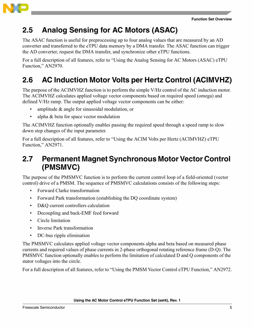
The readme.txt file of the AC motor control eTPU function set, release 1.0, states the following performance values:
Funct. | Mode of operation | max eTPU busy time per | eTPU cycles-------+--------------------------------+------------------------+------------PWMMAC | modulation: SVM Stand./U0n/U7n | one period | 1340with | update: normal | period-update time | 362PWMF | number of phases: 3 | Minimum update time | 1172phases | phases type: compl. pairs | Longest thread | 402-------+--------------------------------+------------------------+------------QD | Slow - Phase A + Phase B | one encoder pulse | 622 | Slow - Phase A + B and Index | one encoder pulse | 718 | | Longest thread | 218 | Normal - Phase A + Phase B | one encoder pulse | 660 | Normal - Phase A + B and Index | one encoder pulse | 720 | | Longest thread | 232 | Fast - Phase A + Phase B | one encoder pulse | 246 | Fast - Phase A + B and Index | one encoder pulse | 310 | | Longest thread | 246-------+--------------------------------+------------------------+------------PMSMVC | Slave mode, | one update | 998 | Circle limitation ON | Longest thread | 546-------+--------------------------------+------------------------+------------SC | Slave mode, QD, PI controller | one update | 310-------+--------------------------------+------------------------+------------BC | Slave mode, PWM switching | one update | 64 | Slave mode, PWM switching | one PWM edge | 20-------+--------------------------------+------------------------+------------ASAC | command queue is generated | one 1st ASAC edge | 112 +--------------------------------+------------------------+------------ | all samples A,B,C,D processed, | | | 2 phase currents measured, | | | 3rd phase current is calculated| | | DTC calculation is ON | one 2nd ASAC edge | 364-------+--------------------------------+------------------------+------------
The contribution of the PWMMAC with PWMF functions to the overall eTPU time load (CPWMMAC+PWMF) is dependent on the PWM period. The PWM period, in eTPU cycles, is equal to a quotient of eTPU frequency (128 MHz) and PWM frequency (20 kHz).
The contribution of the QD function to the overall eTPU time load (CQD) is dependent on the number of shaft encoder pulses (500) and the motor speed (maximum 1000rpm).
CPWMMAC PWMF+1340
128MHz 20kHz------------------------------------------ 0.209= =
CQD660
128MHz 60 1000rpm 500 ----------------------------------------------------------------------------------
60128MHz 60 1000rpm
--------------------------------------------------------------------+ 0.043= =
Using the AC Motor Control eTPU Function Set (set4), Rev. 1
Freescale Semiconductor 15

Function Set Description
The contribution of the PMSMVC function to the overall eTPU time load (CPMSMVC) is dependent on the update period. The PMSMVC update is executed every PWM period. The PMSMVC update frequency is 20 kHz.
The contribution of the SC function to the overall eTPU time load (CSC) is dependent on the update period. The SC update is executed every 4th PWM period. The SC update frequency is 5 kHz.
The contribution of the BC function to the overall eTPU time load (CBC) is dependent on the update period. The BC update is executed every 4th PWM period. The BC update frequency is 5 kHz.
The contribution of the ASAC function to the overall eTPU time load (CASAC) is dependent on the update period. During an update, both the first and then the second edges are processed. The ASAC update is executed every PWM period. The ASAC update frequency is 20 kHz.
The average eTPU time load results in 50%, which is the sum of all active eTPU function contributions:
The peak eTPU time load comes up during the PWM period in which the SC update, the BC update and one BC PWM edge are processed. The other eTPU functions consume a constant eTPU time each PWM period, while the SC and the BC function, whose update is executed every 4th period, consumes in this period 4-times more than on average. Moreover the contribution of the BC PWM edge processing must be included in the peak load calculation.
The peak eTPU time load results in 54.5%.
In order to ensure an efficient usage of eTPU engine time, and the correct functionality of the QD (which means ensuring that all encoder transitions are handled), additional calculations need to be done. This will be described in the following chapter.
4.3.2 eTPU Timing ConfigurationUp to now, eTPU average time load and peak time load relating to one PWM period have been discussed. Now, the timing within one PWM period, and its configuration, will be explained.
Most of the AC motor control eTPU functions (ACIMVHZ, ACIMVC, PMSMVC, SC, BC, and ASAC, in master mode, as well as PWMMAC) have a parameter start offset and a parameter period. These
CPMSMVC998
128MHz 20kHz------------------------------------------ 0.156= =
CSC310
128MHz 5kHz--------------------------------------- 0.012= =
CBC64
128MHz 5kHz--------------------------------------- 0.003= =
CASAC112 364+
128MHz 20kHz------------------------------------------ 0.074= =
eTPULoadaverage C= PWMMAC PWMF+ C+ QD CPMSMVC CSC CBC C+ + + ASAC+
eTPULoadaverage 0.209 0.043 0.156 0.012 0.003 0.074+ + + + + 0.497= =
eTPULoadpeak C= PWMMAC PWMF+ C+ QD CPMSMVC 4+ C SC 4 CBC C+ + ASAC20
128MHz 20kHz------------------------------------------+ + 0.545=
Using the AC Motor Control eTPU Function Set (set4), Rev. 1
Freescale Semiconductor16

Function Set Description
parameters are used to synchronize the functions. The PWMMAC period parameter defines the PWM period. The ACIMVHZ, ACIMVC, PMSMVC, SC, BC, and ASAC periods should be set to an integer multiple of the PWM period, in order to keep all the functions synchronized. The start offset defines the time from the start of the eTPU time bases to the first function action, which is an update on ACIMVHZ, ACIMVC, PMSMVC, SC and BC, first edge on ASAC, and PWM period edge on PWMMAC. The differences between the start offsets of each function determine the relative time shifts between the eTPU function actions.
If the ACIMVHZ, ACIMVC, PMSMVC, SC or BC functions run in slave mode, its update is executed on a link from another channel (usually the ASAC), which determines the timing. If the ASAC function runs in PWM-synchronized mode, its timing is determined by the edge offset parameter, which defines the offset between the PWM period edge time and the ASAC first edge.
There is a PWMMAC parameter, called update time, which is very important for motor control eTPU application timing. The update time is the time period needed to coherently update all PWM phases by new duty-cycle values. If the update time is correctly set, and a new PWMMAC input voltage is written before the update time prior to the PWM period end, the PWM phases are coherently updated, applying the new duty cycles from the next PWM period. If the new input voltage is written later, the PWM phases are not updated from the next PWM period but from the following one. The minimum update time for each configuration of PWMMAC with PWMF is written in the table of performance values, included with the function set release in the readme.txt file. This value can be applied in the case when no other eTPU function could interfere in the sequence of update threads. The eTPU functions running synchronously with the PWM periods (ACIMVHZ, ACIMVC, PMSMVC, SC, BC, ASAC) can be configured to execute in other parts of the PWM period, and hence not interfere in the PWM update process. The eTPU functions running asynchronously with the PWM periods (QDs) can interfere, and the eTPU update time needs to be prolonged.
The following examples show the configuration of eTPU timing for a couple of particular applications.
4.3.2.1 Example 1: AC Induction Motor V/Hz Control Open LoopLet’s recall, the application utilizes the PWMMAC with PWMF and ACIMVHZ eTPU functions. The PWM period, according to 4.3.1.1, is 75 MHz/20 kHz = 3750 eTPU cycles.
The readme.txt file of the AC motor control eTPU function set, release 1.0, states the following performance values:
Funct. | Mode of operation | max eTPU busy time per | eTPU cycles-------+--------------------------------+------------------------+------------PWMMAC | modulation: user table | one period | 1384with | update: normal | period-update time | 410PWMF | number of phases: 3 | Minimum update time | 1216phases | phases type: compl. pairs | Longest thread | 398-------+--------------------------------+------------------------+------------ACIMVHZ| Master mode, Speed Ramp ON, | | | Amplitude-Angle mode | one update | 186-------+--------------------------------+------------------------+------------
Using the AC Motor Control eTPU Function Set (set4), Rev. 1
Freescale Semiconductor 17

Function Set Description
Figure 4. Example 1 Timing Diagram
At first, the PWM update time should be calculated. As stated above, the minimum update time is 1216 eTPU cycles. No other processing, which is asynchronous to the PWM period frames, could interfere in the PWM update. Hence the PWM update time must be set to 1216 eTPU cycles, or more:
NOTEThe update time is not assigned in eTPU cycles, but in TCR1 cycles in thePWMMAC API initialization routine. For motor control applications, thefastest TCR1 clock, which is half of the eTPU clock, is recommended. Inthis case, the update time is 1216/2 = 608 TCR1 cycles.
The PWMMAC start offset defines the time of the first PWM period edge. It could be almost any number, because it’s not the number itself, but the difference between function start offsets, that defines the eTPU application timing, the relative positions between function actions. Let’s set the PWMMAC start offset to 20000 eTPU cycles, which is 10000 TCR1 cycles in the case of the fastest TCR1 clock configuration:
ACIMVHZ is running in master mode. The ACIMVHZ period must be set as an integer multiple of the PWM period. The ACIMVHZ start offset defines the time position of the ACIMVHZ update execution. It should be set so that the PWMMAC can take over the updated values of angle and amplitude at the PWM update time prior to the PWM period end, even in the worst timing case.
PWM period
PWM update time
PWMMAC
PWMF
PWMF
PWMF
PWMF
PWMF
PWMF
ACIMVHZ
eTPU engine is busy
eTPU channel is serviced
channel service latency
link service request between channels
PWMMACstart offset
ACIMVHZstart offset
update_timePWMMAC 1216
start_offsetPWMMAC 20000 eTPU cycles=
Using the AC Motor Control eTPU Function Set (set4), Rev. 1
Freescale Semiconductor18

Function Set Description
In order to ensure this, let’s count all the eTPU channel activities which could appear in this period:
• The ACIMVHZ update itself takes 186 eTPU cycles.
• The processing of the PWMMAC and PWMF functions could take up to 410 eTPU cycles.
The ACIMVHZ start offset must be set to 21938 eTPU cycles, or slightly less, which is 10969 TCR1 cycles in case of the fastest TCR1 clock configuration. It defines the position of the ACIMVHZ update execution as slightly after the middle of the PWM period frame.
The described timing configuration is shown in Figure 4.
In simple cases similar to the example 1, in which PWM functions and only one controller function run in parallel, the most simple and quick way how to set the timing is to set the update time to the half of PWM period and the time of the first half of PWM period allocate for controllers. The ACIMVHZ start offset can be set to the same value as PWMMAC start offset, causing the ACIMVHZ updates are executed at the beginning of the PWM period and thus ensuring all controller calculations are done before the first half of PWM period, see Figure 6. This is applicable for simple configurations of eTPU functions, the complicated cases should be analyzed in detail as described in the following paragraphs.
4.3.2.2 Example 2: PMSM with Quadrature Encoder, Speed Vector ControlLet’s recall, the application utilizes the PWMMAC with PWMF, QD, PMSMVC, SC, BC, and ASAC eTPU functions. The PWM period, according to 4.3.1.2, is 128 MHz/20 kHz = 6400 eTPU cycles.
The readme.txt file of the AC motor control eTPU function set, release 1.0, states the following performance values:
Funct. | Mode of operation | max eTPU busy time per | eTPU cycles-------+--------------------------------+------------------------+------------PWMMAC | modulation: SVM Stand./U0n/U7n | one period | 1340with | update: normal | period-update time | 362PWMF | number of phases: 3 | Minimum update time | 1172phases | phases type: compl. pairs | Longest thread | 402-------+--------------------------------+------------------------+------------QD | Slow - Phase A + Phase B | one encoder pulse | 622 | Slow - Phase A + B and Index | one encoder pulse | 718 | | Longest thread | 218 | Normal - Phase A + Phase B | one encoder pulse | 660 | Normal - Phase A + B and Index | one encoder pulse | 720 | | Longest thread | 232 | Fast - Phase A + Phase B | one encoder pulse | 246 | Fast - Phase A + B and Index | one encoder pulse | 310 | | Longest thread | 246-------+--------------------------------+------------------------+------------PMSMVC | Slave mode, | one update | 998 | Circle limitation ON | Longest thread | 546-------+--------------------------------+------------------------+------------SC | Slave mode, QD, PI controller | one update | 310
start_offsetACIMVHZ start_offsetPWMMAC period+ PWM update_timePWMMAC 186 410+ + eTPU cycles–
start_offsetACIMVHZ 20000 3750+ 1216 186 410+ + 21938 eTPU cycles=–
Using the AC Motor Control eTPU Function Set (set4), Rev. 1
Freescale Semiconductor 19

Function Set Description
-------+--------------------------------+------------------------+------------BC | Slave mode, PWM switching | one update | 64 | Slave mode, PWM switching | one PWM edge | 20-------+--------------------------------+------------------------+------------ASAC | command queue is generated | one 1st ASAC edge | 112 +--------------------------------+------------------------+------------ | all samples A,B,C,D processed, | | | 2 phase currents measured, | | | 3rd phase current is calculated| | | DTC calculation is ON | one 2nd ASAC edge | 364-------+--------------------------------+------------------------+------------
Figure 5. Example 2 Timing Diagram
At first, the PWM update time should be calculated. As stated above, the minimum update time is 1172 eTPU cycles. The QD processing, which is asynchronous to the PWM period frames, could interfere in the PWM update. The time of one 500-pulse shaft encoder pulse, at the maximum motor speed (1000rpm), is:
The QD, while not running in fast mode, process 4 transitions per one shaft encoder pulse. Approximately every 3840 eTPU cycles (15360/4) one transition must be processed. Therefore, a maximum of one QD transitions could interfere in the PWM update. Let’s assume that the longest thread of normal mode occurs in the worst case. Hence:
The PWM update time must be set to 1418 eTPU cycles, or more, which is 709 TCR1 cycles, in the case of the fastest TCR1 clock configuration.
PWM period
PWM update time
PWMMAC
PWMF
PWMF
PWMF
PWMF
PWMF
PWMF
PMSMVC
ASAC
SC
measure time
eTPU engine is busy
eTPU channel is serviced
channel service latency
link service request between channels
BC
min_pulse_timeQD 128MHz 60 1000rpm 500 15360 eTPU cycles= =
update_timePWMMAC 1172 246+ 1418 eTPU cycle=
Using the AC Motor Control eTPU Function Set (set4), Rev. 1
Freescale Semiconductor20

Function Set Description
The PWMMAC start offset can be, again, set to 20000 eTPU cycles, which is 10000 TCR1 cycles in the case of the fastest TCR1 clock configuration:
The ASAC function is running in PWM synchronized mode. The ASAC first edge, which is the AD converter trigger edge, is always scheduled relative to the PWM period edge. The best phase current sampling time point is located at the beginning of the PWM period. So, the edge offset should be set to 0 or slightly less in case there are some delays between the ASAC first edge and the AD converter triggering. The ASAC measure time is the time after which the converted sample values are ready in eTPU DATA RAM. It must be set according to the AD converter and DMA transfer configuration.
The PMSMVC function is running in slave mode. The PMSMVC updates are executed by link from the ASAC, on the second ASAC edge, every PWM period.
The SC function is also running in slave mode. The SC updates are executed by link from the ASAC, on the first ASAC edge, every defined number of PWM periods.
The BC function is also running in slave mode. The BC updates are executed by link from the SC every SC update.
The described timing configuration is shown in Figure 5.
4.3.2.3 Checking eTPU Timing Using an Oscilloscope or Logic AnalyzerThe eTPU functions which are not intended to process an input or output signal (PWMMAC, ACIMVHZ, ACIMVC, PMSMVC, SC) support checking the eTPU timing using an oscilloscope or logic analyzer. The functions turn the output pin high and low, so that the high-time identifies the time period in which an event service is executed. Generally, these functions can be assigned to channels which are not connected to any device pin, because the generated signals are not needed to drive a motor. But if they are, the generated signals can be used to check the eTPU timing for the particular application using an oscilloscope or logic analyzer.
The oscilloscope should be synchronized with the PWM period frames. This can be achieved, for example, by setting a trigger on the signal generated by the ASAC. In case the ASAC is not in use, a signal generated by any eTPU function, running in master mode (ACIMVHZ, ACIMVC, PMSMVC, SC), could also serve as the trigger. The signal pulse generated by the ACIMVHZ, ACIMVC, PMSMVC, SC, BC, or PWMMAC, determines the period of time in which a function event service is executed. The pulse width determines the service time. The pulse width variance, which is well seen on an analog oscilloscope or a digital oscilloscope with the signal envelope feature, determines the service time variance. The pulse position, relative to the PWM period frames, determines the eTPU application timing. If the timing is not as desired, the start offsets should be corrected. And finally, the pulse position variance determines the service latency variance.
The timing can be checked in various conditions: over the whole range of the motor speed, in a fault state, in the case of activity on other eTPU channels, etc.
start_offsetPWMMAC 20000 eTPU cycles=
Using the AC Motor Control eTPU Function Set (set4), Rev. 1
Freescale Semiconductor 21
Function Set Description
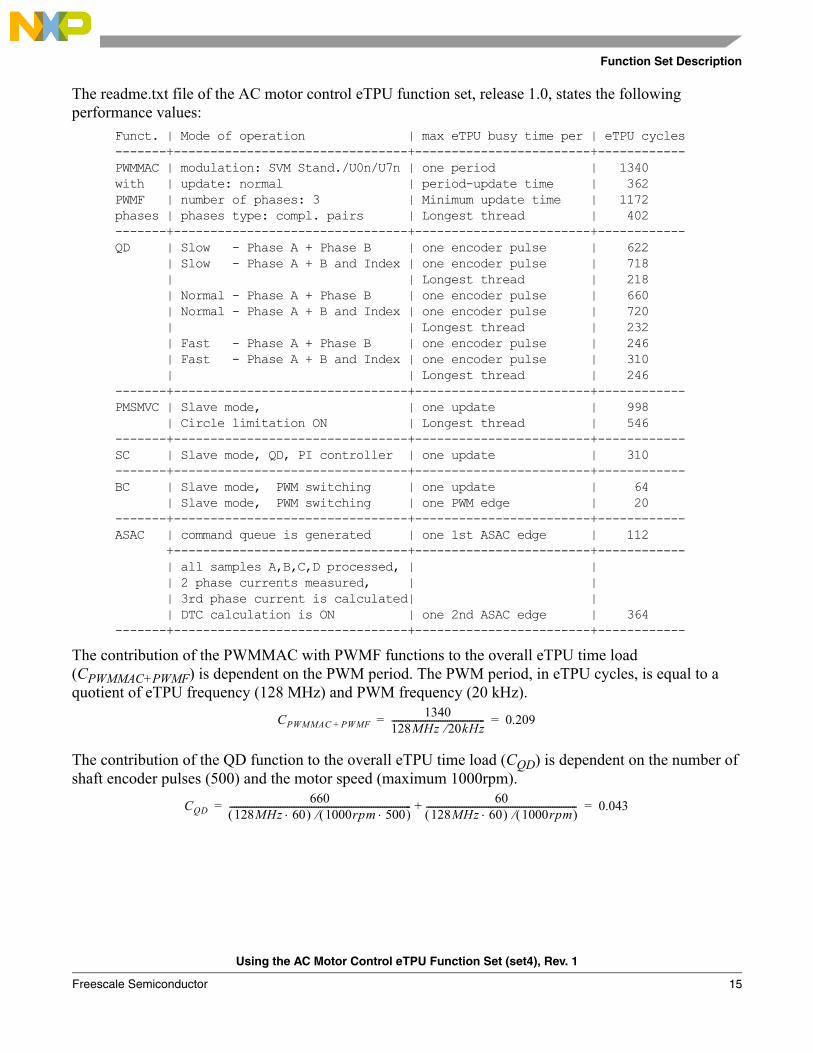
Figure 6. Example 1 Application Timing - Logic Analyser Checking
Figure 7. Example 2 Application Timing - Logic Analyser Checking
4.3.3 Setting Channel PrioritiesProper settings of eTPU channel priorities can improve the eTPU application performance. In motor control eTPU applications, it is recommended to keep the following priority assignment:
• Priority low: ACIMVHZ, ACIMVC, PMSMVC, SC, BC
• Priority middle: PWMMAC with PWMF, ASAC
PWM period
ACIMVHZ
PWMupdate
time
PWMMAC
PWMMAC providescoherent update of all
PWM phases
PWMF
PWMF
PWMF
PWMF
PWMF
PWMF
PWMMAC takesover new applied voltage
vector components
ACIMVHZupdate
QD
QD
SC
PMSMVCPWMMAC
PWMF
ASAC
PWMF
PWMF
PWMF
PWMF
PWMF
Using the AC Motor Control eTPU Function Set (set4), Rev. 1
Freescale Semiconductor22

Function Set Description
• Priority high: QD
The QD function should be the only function assigned the high priority in order to achieve a maximum QD performance, and enable easy checking of the maximum allowed motor speed.
To ensure the proper functionality of QD in normal mode, the sum of the longest QD thread in normal mode and the longest thread from another eTPU function must be lower than the time between two QD edges (time of a quarter of one encoder pulse). In fast mode of QD operation, the sum of the longest QD thread in fast mode and the longest thread from another eTPU function must be lower than the time of one encoder pulse. The longest thread of all the AC motor control eTPU functions takes 584 eTPU cycles (ACIMVC). Hence, in the worst case (maximum allowed speed), the processing of a quarter of one encoder pulse takes up to
in normal mode, and one encoder pulse processing takes up to
in the fast mode of QD operation.
Then, the maximum motor speed, at which it is ensured that all QD pulses are processed, is:
for normal mode of QD operation, and:
for fast mode of QD operation.
Let’s enter the values of the eTPU module clock and the number of the shaft encoder pulses from example 2:
The QD function can operate in normal mode up to a speed of 3087 rpm, which should be set as a threshold for switching to the fast mode. In fast mode, it can operate up to a speed of 18506 rpm.
On some PowerPC MPC5500 devices with two eTPU engines, a better performance of QD can be achieved if the QD function runs on the other eTPU engine.
min_quarter_of_pulse_timeQDnormal 660 584+ 1244 eTPU cycles= =
min_pulse_timeQDfast 246 584+ 830 eTPU cycles= =
max_speedQDnormaleTPU_clock_freq 60
number_of_encoder_pulses 1244 4 ------------------------------------------------------------------------------------------=
max_speedQDfasteTPU_clock_freq 60
number_of_encoder_pulses 830-------------------------------------------------------------------------------=
max_speedQDnormal128MHz 60500 1244 4 --------------------------------- 3087 rpm= =
max_speedQDfast128MHz 60
500 830-------------------------------- 18506 rpm= =
Using the AC Motor Control eTPU Function Set (set4), Rev. 1
Freescale Semiconductor 23

Summary and Conclusions
5 Summary and ConclusionsThis application note provides the user with a description of the AC motor control eTPU function set (set4), and its usage in applications.
References:
• eTPU General:
1. “The Essentials of Enhanced Time Processing Unit,” AN2353.2. “General C Functions for the eTPU,” AN2864.3. Enhanced Time Processing Unit Reference Manual, ETPURM/D.4. eTPU Graphical Configuration Tool, http://www.freescale.com/etpu, ETPUGCT.• eTPU Functions:
5. “Using the General Purpose Input/Output (GPIO) eTPU Function,” AN2850.6. “Using the AC Motor Control PWM eTPU Functions,” AN2969.7. “Using the Quadrature Decoder (QD) eTPU Function,” AN2842.8. “Using the Resolver Interface (RSLV) eTPU Function,” AN3943.9. “Using the Analog Sensing for AC Motors (ASAC) eTPU Function,” AN2970.10. “Using the ACIM Volts per Hertz (ACIMVHZ) eTPU Function,” AN2971.11. “Using the PMSM Vector Control eTPU Function,” AN2972.12. “Using the ACIM Vector Control eTPU Function,” AN2973.13. “Using the Speed Controller (SC) eTPU Function,” AN2843.14. “Using the Break Controller (BC) eTPU Function,” AN2845.• eTPU Demo Applications:
15. “AC Induction Motor V/Hz Control, Driven by eTPU on MCF523x,” AN3000.16. “Permanent Magnet Synchronous Motor Vector Control, Driven by eTPU on MCF523x,”
AN3002.17. “Permanent Magnet Synchronous Motor Vector Control, Driven by eTPU on MPC5500,”
AN3206.18. “Permanent Magnet Synchronous Motor with Resolver, Vector Control, Driven by eTPU on
MPC5500,” AN4480.19. “AC Induction Motor Vector Control, Driven by eTPU on MPC5500,” AN3001.20. “AC Induction Motor V/Hz Control with Speed Closed Loop, Driven by eTPU on MPC5500,”
AN3205.
6 Revision historyTable 1. Revision history
Revision number Revision date Description of changes
1 01 May 2012 Updated for support of motor drives with resolver position sensor.
Using the AC Motor Control eTPU Function Set (set4), Rev. 1
Freescale Semiconductor24

Revision history
Using the AC Motor Control eTPU Function Set (set4), Rev. 1
Freescale Semiconductor 25

Document Number: AN2968Rev. 102/2012
Information in this document is provided solely to enable system and software
implementers to use Freescale products. There are no express or implied copyright
licenses granted hereunder to design or fabricate any integrated circuits based on the
information in this document.
Freescale reserves the right to make changes without further notice to any products
herein. Freescale makes no warranty, representation, or guarantee regarding the
suitability of its products for any particular purpose, nor does Freescale assume any
liability arising out of the application or use of any product or circuit, and specifically
disclaims any and all liability, including without limitation consequential or incidental
damages. “Typical” parameters that may be provided in Freescale data sheets and/or
specifications can and do vary in different applications, and actual performance may
vary over time. All operating parameters, including “typicals,” must be validated for each
customer application by customer’s technical experts. Freescale does not convey any
license under its patent rights nor the rights of others. Freescale sells products
pursuant to standard terms and conditions of sale, which can be found at the following
address: http://www.reg.net/v2/webservices/Freescale/Docs/TermsandConditions.htm
How to Reach Us:
Home Page: freescale.com
Web Support: freescale.com/support
Freescale, the Freescale logo, AltiVec, C-5, CodeTest, CodeWarrior, ColdFire, C-Ware,
Energy Efficient Solutions logo, Kinetis, mobileGT, PowerQUICC, Processor Expert,
QorIQ, Qorivva, StarCore, Symphony, and VortiQa are trademarks of Freescale
Semiconductor, Inc., Reg. U.S. Pat. & Tm. Off. Airfast, BeeKit, BeeStack, ColdFire+,
CoreNet, Flexis, MagniV, MXC, Platform in a Package, QorIQ Qonverge, QUICC
Engine, Ready Play, SafeAssure, SMARTMOS, TurboLink, Vybrid, and Xtrinsic are
trademarks of Freescale Semiconductor, Inc. All other product or service names are
the property of their respective owners. The Power Architecture and Power.org
word marks and the Power and Power.org logos and related marks are
trademarks and service marks licensed by Power.org.
© 2006, 2012 Freescale Semiconductor, Inc.