Embed Size (px)
Citation preview
08 Fall
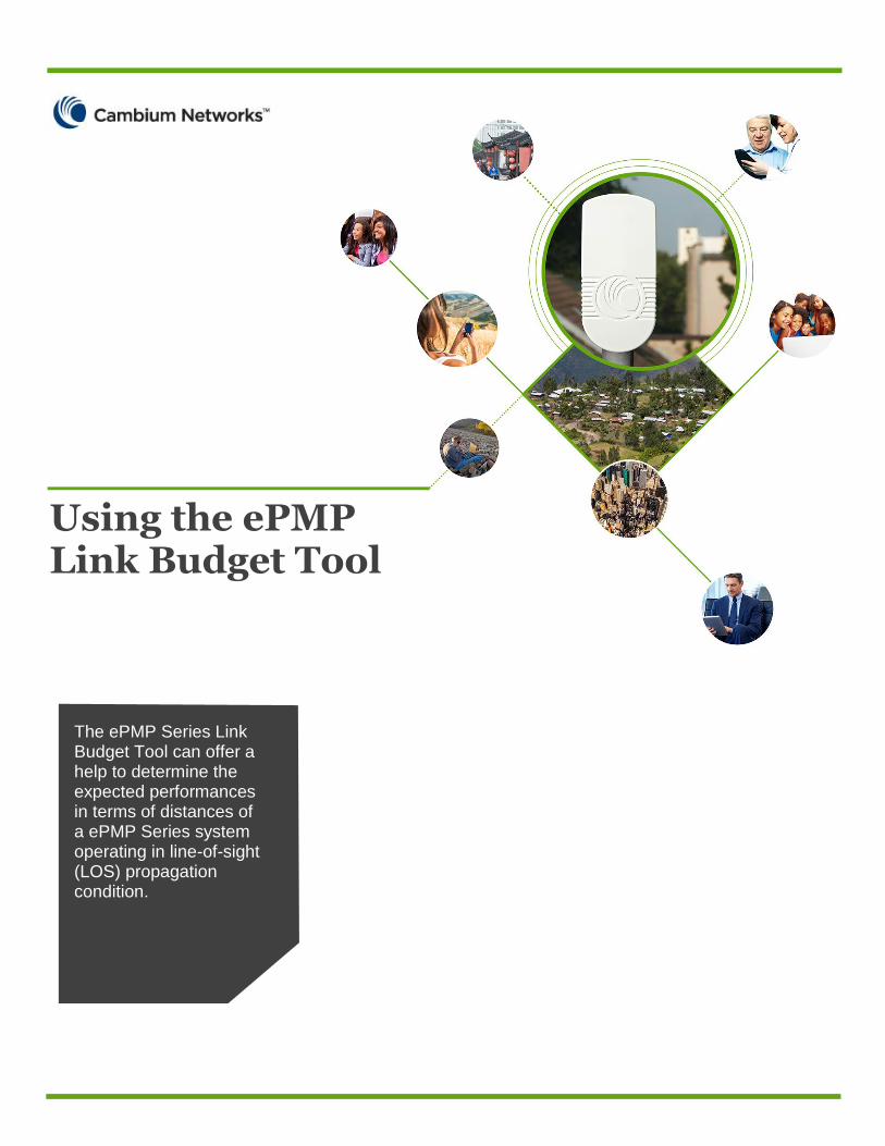
The ePMP Series Link Budget Tool can offer a help to determine the expected performances in terms of distances of a ePMP Series system operating in line-of-sight (LOS) propagation condition.
Using the ePMP Link Budget Tool
CAMBIUM NETWORKS
2
ePMP Series introduction
The purpose of this document is to provide a quick description on how to use the ePMP
Series Link Budget Tool. The Cambium Networks ePMP Series is a wireless access system
designed to create a radio local area network (RLAN) through microwave links in a point-
to-multipoint mode operating in the 5 GHz unlicensed bands. The ePMP Series Link
Budget Tool can offer a quick help to determine the expected performances in terms of
distances of a ePMP Series system operating in line-of-sight (LOS) propagation condition
according to the configuration of several system parameters like channel bandwidth and
antenna selection.
The ePMP System creates a point-to-multipoint wireless broadband connection
transmitting a radio signal with OFDM modulation and MIMO transmission technique.
OFDM (Orthogonal Frequency Division multiplexing) is a multi-carrier radio signal
modulation based on the subdivision of the broadband channel into orthogonally-
positioned subcarriers, each of which is modulated based on a conventional modulation
Country
Frequency band 5.7/5.8 [GHz] 5725 [MHz]
Fade Margin 0 [dB] 5875 [MHz]
Channel Bandwidth 20 [MHz] 36 [dBm] 4.000 [Watts]
AP antenna system 23 [dBm] 200 [mWatts]
Environment - [dBm] - [Watts]
Max range 5 [miles] 23 [dBm] 200 [mWatts]
Max range limit 15.93 [miles]
Frame duration 5.0 [ms]
Number of STAs/sector
Duty cycle
UDP payload size 1472 [bytes]
Interference level 0 [dBm]
AP Tx Power per chain 20 [dBm] 0.100 [Watts] 20 [dBm] 0.100 [Watts]
Cable Loss 1.0 [dB] 0.001 [Watts]
AP Antenna Gain 15 [dBi] 13 [dBi]
AP EIRP 34 [dBm] 2.512 [Watts] 33 [dBm] 2.0 [Watts]
-68 [dBm] 64QAM 5/6 MCS15 -70 [dBm] 64QAM 5/6 MCS15
-70 [dBm] 64QAM 3/4 MCS14 -71 [dBm] 64QAM 3/4 MCS14
-73 [dBm] 64QAM 2/3 MCS13 -73 [dBm] 64QAM 2/3 MCS13
-77 [dBm] 16QAM 3/4 MCS12 -78 [dBm] 16QAM 3/4 MCS12
-82 [dBm] 16QAM 1/2 MCS11 -81 [dBm] 16QAM 1/2 MCS11
-83 [dBm] QPSK 3/4 MCS10 -84 [dBm] QPSK 3/4 MCS10
-87 [dBm] QPSK 1/2 MCS9 -86 [dBm] QPSK 1/2 MCS9
-90 [dBm] QPSK 1/2 SS MCS1 -89 [dBm] QPSK 1/2 SS MCS1
28 [dB] 64QAM 5/6 MCS15 30 [dB] 64QAM 5/6 MCS15
27 [dB] 64QAM 3/4 MCS14 28 [dB] 64QAM 3/4 MCS14
25 [dB] 64QAM 2/3 MCS13 25 [dB] 64QAM 2/3 MCS13
20 [dB] 16QAM 3/4 MCS12 21 [dB] 16QAM 3/4 MCS12
17 [dB] 16QAM 1/2 MCS11 16 [dB] 16QAM 1/2 MCS11
14 [dB] QPSK 3/4 MCS10 15 [dB] QPSK 3/4 MCS10
12 [dB] QPSK 1/2 MCS9 11 [dB] QPSK 1/2 MCS9
9 [dB] QPSK 1/2 SS MCS1 8 [dB] QPSK 1/2 SS MCS1
STA Antenna Gain 13 [dBi] 1.0 [dB] 0.001 [Watts]
15 [dBi]
The link is uplink limited by 1 dB
Modulation
64QAM 5/6 MCS15 115.0 dB 1.42 mi 2.28 km 39.6 Mbps 30.4 Mbps 70.0 Mbps DL 21.8
64QAM 3/4 MCS14 117.0 dB 1.79 mi 2.88 km 36.0 Mbps 26.2 Mbps 62.2 Mbps UL 16.6
64QAM 2/3 MCS13 120.0 dB 2.52 mi 4.06 km 32.4 Mbps 24.2 Mbps 56.6 Mbps Total 38.3
16QAM 3/4 MCS12 124.0 dB 4.00 mi 6.44 km 23.4 Mbps 18.2 Mbps 41.6 Mbps
16QAM 1/2 MCS11 128.0 dB 6.34 mi 10.20 km 16.2 Mbps 12.2 Mbps 28.4 Mbps
QPSK 3/4 MCS10 130.0 dB 7.98 mi 12.85 km 12.6 Mbps 8.0 Mbps 20.6 Mbps DL 17.5
QPSK 1/2 MCS9 133.0 dB 11.27 mi 18.14 km 7.2 Mbps 6.0 Mbps 13.2 Mbps UL 16.1
QPSK 1/2 SS MCS1 136.0 dB 15.93 mi 25.63 km 3.6 Mbps 2.0 Mbps 5.6 Mbps Total 33.6
STA CINR AP CINR
Scheduling latency (ms)
COVERAGE AND CAPACITYCapacity (Mbps)
90° sector
SYSTEM CONFIGURATION
System Gain
Internal SM antenna
UPLINK BUDGET (STA to AP)
Upper frequency
STA EIRP
Max UL ThroughputPotential Range
Cable Loss
AP Antenna Gain
Max Total Throughput
Internal SM antenna
Max DL Throughput
90° sector
ePMP LINK BUDGET CALCULATOR
DOWNLINK BUDGET (AP to STA)
90° sector
FCC
Max AP Tx Power
STA EIRP limit
Lower frequency
Cambium Networks confidential, not commercially binding
STA Tx Power per chain
rural
Max STA Tx Power
AP EIRP limit
STA Rx Sensitivity
20
50/50
STA Antenna Gain
AP Rx Sensitivity
CAMBIUM NETWORKS
3
scheme. With the OFDM technique, a very high data rate can be obtained increasing the
system’s spectrum efficiency.
The following are the subcarriers modulation schemes which can be used by the ePMP
System:
• QPSK
• 16-QAM
• 64-QAM
Each modulation supports multiple coding rates. For example 64-QAM supports coding
rates 5/6, 3/4 and 2/3.
The OFDM channel bandwidth can be configured with one of two possible values: 20 MHz
and 40 MHz. 40 MHz channel bandwidth configurations allow for greater connection
capacity as the signal occupies a larger portion of the spectrum. The narrower channel
bandwidth (20 MHz) increases reception sensitivity and allows for more opportunities to
operate in spectrum-constrained RF environments.
The channel bandwidth must be configured with the same values in both the AP and SM
modules of the ePMP System.
MIMO (Multiple Input Multiple Output) radio transmission offers the capability of
increasing the capacity of a radio connection by transmitting and receiving parallel signals
on separate Tx/Rx chains. When the benefits of the MIMO techniques are combined with
OFDM signaling and high system gain, operators can achieve a highly robust radio
connection in conditions of non-line-of-sight (NLOS) propagation. The ePMP System uses
2x2 MIMO with two radio receivers and two transmitters in both the AP module and the
STA module, transmitting in both directions two radio signals in the same frequency. One
signal is vertically polarized and the other signal is horizontally polarized, with dual
stream mode: the system transmits two distinct parallel data flows – one by way of the
vertically polarized radio signal and the other by way of the horizontally polarized radio
signal. In this way, the ePMP System doubles its transmission capacity.
The ePMP system also offers a single stream mode, in which both transmit chains
transmit the same data, which is then combined at the receiver. This mode improves the
sensitity of the system and increases the range.
Cambium Networks offers two section antennas to be used with the AP module of the
ePMP System to create the RF coverage of service areas in multisector sites. The antennas
provided by Cambium Networks are specifically designed to optimize the performance in
terms of radio coverage of the ePMP System:
• 90° sector antenna for sites with up to 4 AP modules
• 120° sector antenna for sites with up to 3 AP modules

CAMBIUM NETWORKS
4
The ePMP Series can provide LOS (Line-Of-Sight), nLOS (near Line-Of-Sight) connectivity
and NLOS (Non-Line-Of-Sight) connectivity. A definition of these different propagation
conditions are the following.
• LOS: the optical line between the AP and the SM and the first Fresnel zone are clear.
• nLOS: the optical line between the AP and the SM is clear, but a portion of the first
Fresnel zone is blocked.
• NLOS: the optical line between the AP and the SM and a portion or even much of the
first Fresnel zone are blocked, but subsequent Fresnel zones are open.
Link budget calculation is applied to a wireless broadband system based on ePMP Series
that is designed in order to operate in LOS propagation conditions with clearance of the
first Fresnel zone.
Attenuation due to building clutter or foliage obstruction can be accounted for by
increasing the fade margin in the link budget calculation.
Link budget calculation
The link budget is the list of all the gains and losses that contribute to the propagation of
the radio frequency signal that travels from the transmitter to the receiver.
The parameters that are taken into account for the calculation of the link budget are
described below:
Transmitter output power: the median power level of the transmitter in the transmission
channel experessed in dBm (relative to milliwatt). This level is configured for the AP
transmitter by the regulatory limits and is automatically adjusted in the SM transmitter
through ATPC (Automatic Transmit Power Control) functionality in order to get the
maximum value.
Cable loss: the loss expressed in dB associated with the coaxial cable used to connect the
transmitter with the antenna. The loss tipically depends on the length of the cable and its
quality.

CAMBIUM NETWORKS
5
Transmitter antenna gain: assuming that the transmitter antenna main axis is oriented in
the direction of the receiver antenna, the maximum gain given in dB declared by the
manufacturer is used.
EIRP (Effective Isotropic Radiated Power): is the sum of the transmitter output power and
transmitter atenna gain minus the cable loss, expressed in dBm.
Receiver antenna gain: assuming that the receiver antenna main axis is oriented in the
direction of the transmitterer antenna, the maximum gain given in dB declared by the
manufacturer is used.
Fade margin: the amount of power given in dB that represents the difference between the
median signal level at the receiver input and the receiver sensitvity. When the link fades
exceeding the fade margin an outage occurs. Fade margin must be selected by the user
according to the link availability target that must be met.
Receiver sensitivity: the minimum median signal level needed at the input of the receiver
to achieve a receiver output quality specific to a particular modulation scheme. Higher
order modulation schemes require higher quality receiver output and higher received
power signal levels.
System Gain: the difference, expressed in dB, between the EIRP and the lowest order
modulation receiver sensitivity and cable loss. It conventionally refers to the minimum of
the uplink and downlink system gains and represents the maximum FSPL achievable with
a particular system configuration.
FSPL (Free Space Path Loss): it represents the radio frequency propagation calculation
used in the tool and is the attenuation between the transmitter antenna and the receiver
antenna in free-space given by the Friis formula:
FSPL [dB] = 32.44 + 20logf + 20logd
Where f is expressed in MHz and d is expressed in kilometers
FSPL [dB] = 36.6 + 20logf + 20logd
Where f is expressed in MHz and d is expressed in miles
This link budget calculation can be considered a valid approximation for LOS propagation
in flat fading conditions where the operating bandwidth is less that the coherence
bandwidth of the radio channel, that is when the same degree of fading affects all
frequencies of the signal bandwidth. In case the radio channel is experiencing frequency-
selective fading effect the LOS range results may not be valid.
Tool settings
CAMBIUM NETWORKS
6
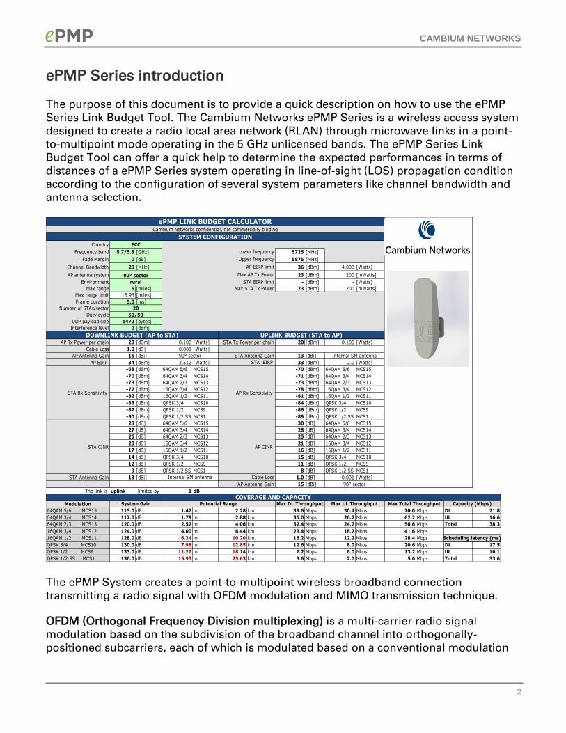
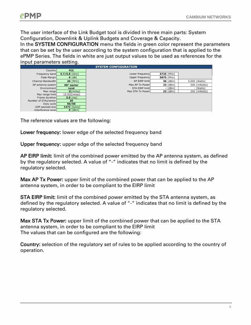
The user interface of the Link Budget tool is divided in three main parts: System
Configuration, Downlink & Uplink Budgets and Coverage & Capacity.
In the SYSTEM CONFIGURATION menu the fields in green color represent the parameters
that can be set by the user according to the system configuration that is applied to the
ePMP Series. The fields in white are just output values to be used as references for the
input parameters setting.
The reference values are the following:
Lower frequency: lower edge of the selected frequency band
Upper frequency: upper edge of the selected frequency band
AP EIRP limit: limit of the combined power emitted by the AP antenna system, as defined
by the regulatory selected. A value of “-“ indicates that no limit is defined by the
regulatory selected.
Max AP Tx Power: upper limit of the combined power that can be applied to the AP
antenna system, in order to be compliant to the EIRP limit
STA EIRP limit: limit of the combined power emitted by the STA antenna system, as
defined by the regulatory selected. A value of “-“ indicates that no limit is defined by the
regulatory selected.
Max STA Tx Power: upper limit of the combined power that can be applied to the STA
antenna system, in order to be compliant to the EIRP limit
The values that can be configured are the following:
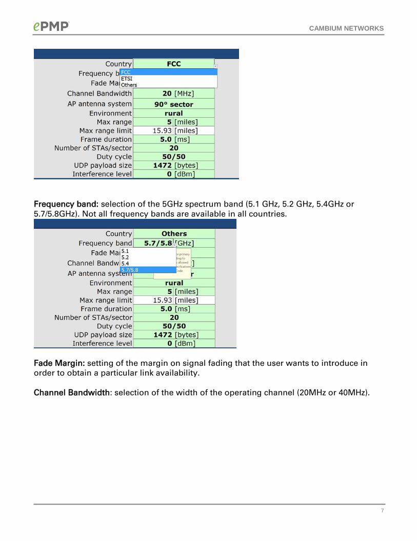
Country: selection of the regulatory set of rules to be applied according to the country of
operation.
Country
Frequency band 5.7/5.8 [GHz] 5725 [MHz]
Fade Margin 0 [dB] 5875 [MHz]
Channel Bandwidth 20 [MHz] 36 [dBm] 4.000 [Watts]
AP antenna system 23 [dBm] 200 [mWatts]
Environment - [dBm] - [Watts]
Max range 5 [miles] 23 [dBm] 200 [mWatts]
Max range limit 15.93 [miles]
Frame duration 5.0 [ms]
Number of STAs/sector
Duty cycle
UDP payload size 1472 [bytes]
Interference level 0 [dBm]
90° sector
SYSTEM CONFIGURATION
Upper frequency
FCC
Max AP Tx Power
STA EIRP limit
Lower frequency
rural
Max STA Tx Power
AP EIRP limit
20
50/50
CAMBIUM NETWORKS
7
Frequency band: selection of the 5GHz spectrum band (5.1 GHz, 5.2 GHz, 5.4GHz or
5.7/5.8GHz). Not all frequency bands are available in all countries.
Fade Margin: setting of the margin on signal fading that the user wants to introduce in
order to obtain a particular link availability.
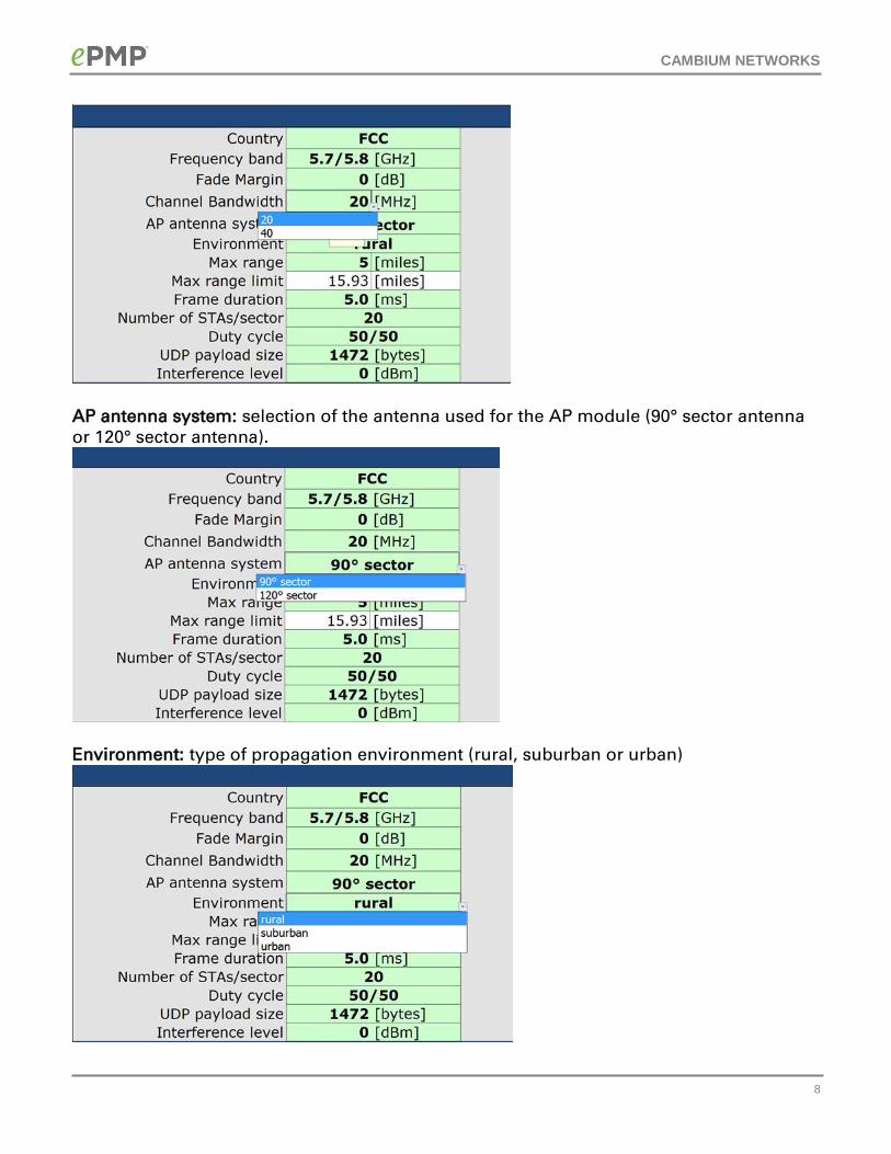
Channel Bandwidth: selection of the width of the operating channel (20MHz or 40MHz).
CAMBIUM NETWORKS
8
AP antenna system: selection of the antenna used for the AP module (90° sector antenna
or 120° sector antenna).
Environment: type of propagation environment (rural, suburban or urban)

CAMBIUM NETWORKS
9
Maximum range: distance (in miles) between the AP and the location of the farther SM the
user wants to serve with the AP. The potential maximum cell size is calculated using other
link budget parameters selected in the green cells and is shown as the Max range limit
(also in miles). If the Maximum range input is larger than the Max range limit, the
Maximum range cell becomes red and an error message appears.
With a smaller cell size, a larger percentage of users can use higher order modulation, and
the sector capacity is higher. On the other hand, with smaller cells network planning
becomes very important, in order to limit interference between sectors using the same
frequency. The Max range limit is a reference value and cannot be changed.
Frame duration: duration (in ms) of the TDD cycle. The first release supports the 5 ms
selection only.
Number of STAs/sector: Number of STAs connected to one AP in one sector. The number
of STAs affects the throughput that can be achieved in a sector, and also the scheduling
latency within the AP.
The maximum number of STAs that can be connected in one sector is 120. If a larger
number is input in this field, an error message appears.
CAMBIUM NETWORKS
10
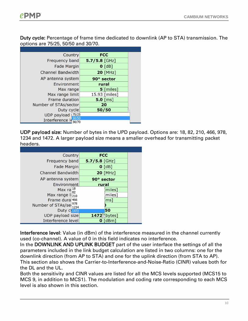
Duty cycle: Percentage of frame time dedicated to downlink (AP to STA) transmission. The
options are 75/25, 50/50 and 30/70.
UDP payload size: Number of bytes in the UPD payload. Options are: 18, 82, 210, 466, 978,
1234 and 1472. A larger payload size means a smaller overhead for transmitting packet
headers.
Interference level: Value (in dBm) of the interference measured in the channel currently
used (co-channel). A value of 0 in this field indicates no interference.
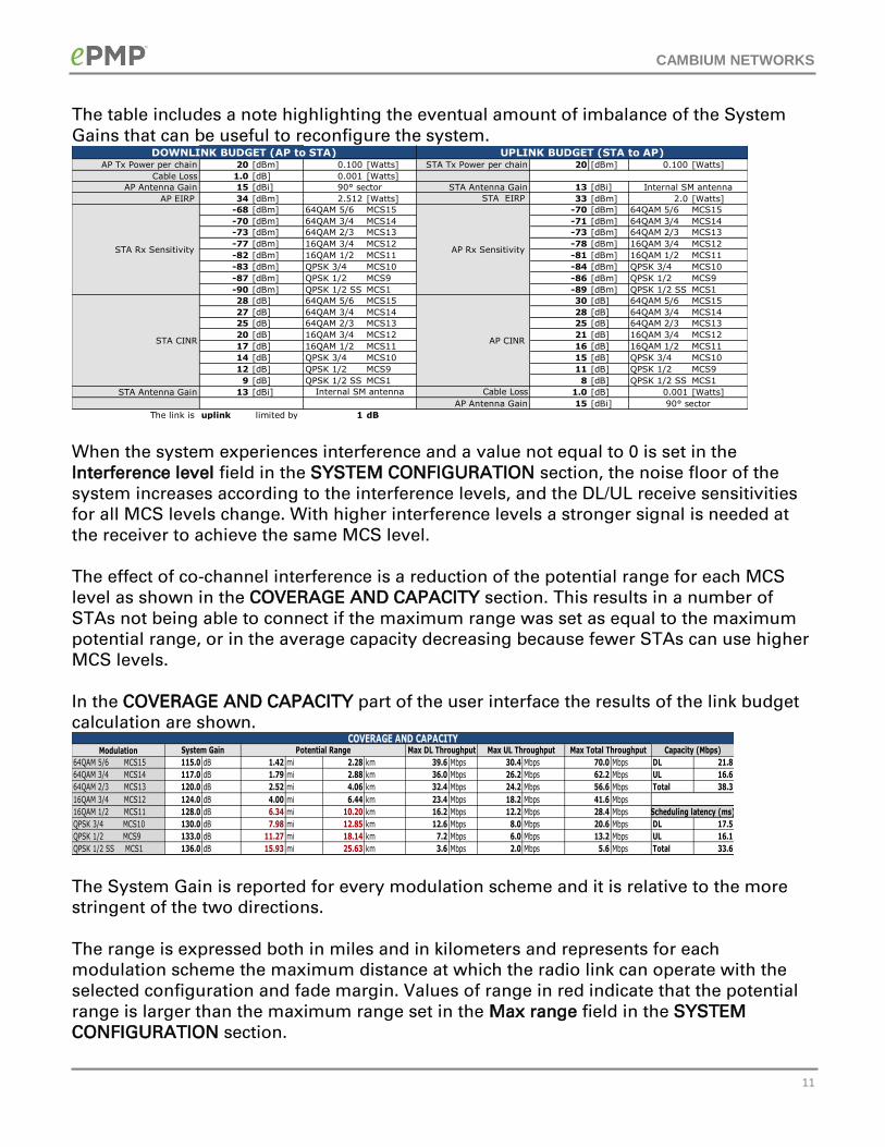
In the DOWNLINK AND UPLINK BUDGET part of the user interface the settings of all the
parameters included in the link budget calculation are listed in two columns: one for the
downlink direction (from AP to STA) and one for the uplink direction (from STA to AP).
This section also shows the Carrier-to-Interference-and-Noise-Ratio (CINR) values both for
the DL and the UL.
Both the sensitivity and CINR values are listed for all the MCS levels supported (MCS15 to
MCS 9, in addition to MCS1). The modulation and coding rate corresponding to each MCS
level is also shown in this section.
CAMBIUM NETWORKS
11
The table includes a note highlighting the eventual amount of imbalance of the System
Gains that can be useful to reconfigure the system.
When the system experiences interference and a value not equal to 0 is set in the
Interference level field in the SYSTEM CONFIGURATION section, the noise floor of the
system increases according to the interference levels, and the DL/UL receive sensitivities
for all MCS levels change. With higher interference levels a stronger signal is needed at
the receiver to achieve the same MCS level.
The effect of co-channel interference is a reduction of the potential range for each MCS
level as shown in the COVERAGE AND CAPACITY section. This results in a number of
STAs not being able to connect if the maximum range was set as equal to the maximum
potential range, or in the average capacity decreasing because fewer STAs can use higher
MCS levels.
In the COVERAGE AND CAPACITY part of the user interface the results of the link budget
calculation are shown.
The System Gain is reported for every modulation scheme and it is relative to the more
stringent of the two directions.
The range is expressed both in miles and in kilometers and represents for each
modulation scheme the maximum distance at which the radio link can operate with the
selected configuration and fade margin. Values of range in red indicate that the potential
range is larger than the maximum range set in the Max range field in the SYSTEM
CONFIGURATION section.
AP Tx Power per chain 20 [dBm] 0.100 [Watts] 20 [dBm] 0.100 [Watts]
Cable Loss 1.0 [dB] 0.001 [Watts]
AP Antenna Gain 15 [dBi] 13 [dBi]
AP EIRP 34 [dBm] 2.512 [Watts] 33 [dBm] 2.0 [Watts]
-68 [dBm] 64QAM 5/6 MCS15 -70 [dBm] 64QAM 5/6 MCS15
-70 [dBm] 64QAM 3/4 MCS14 -71 [dBm] 64QAM 3/4 MCS14
-73 [dBm] 64QAM 2/3 MCS13 -73 [dBm] 64QAM 2/3 MCS13
-77 [dBm] 16QAM 3/4 MCS12 -78 [dBm] 16QAM 3/4 MCS12
-82 [dBm] 16QAM 1/2 MCS11 -81 [dBm] 16QAM 1/2 MCS11
-83 [dBm] QPSK 3/4 MCS10 -84 [dBm] QPSK 3/4 MCS10
-87 [dBm] QPSK 1/2 MCS9 -86 [dBm] QPSK 1/2 MCS9
-90 [dBm] QPSK 1/2 SS MCS1 -89 [dBm] QPSK 1/2 SS MCS1
28 [dB] 64QAM 5/6 MCS15 30 [dB] 64QAM 5/6 MCS15
27 [dB] 64QAM 3/4 MCS14 28 [dB] 64QAM 3/4 MCS14
25 [dB] 64QAM 2/3 MCS13 25 [dB] 64QAM 2/3 MCS13
20 [dB] 16QAM 3/4 MCS12 21 [dB] 16QAM 3/4 MCS12
17 [dB] 16QAM 1/2 MCS11 16 [dB] 16QAM 1/2 MCS11
14 [dB] QPSK 3/4 MCS10 15 [dB] QPSK 3/4 MCS10
12 [dB] QPSK 1/2 MCS9 11 [dB] QPSK 1/2 MCS9
9 [dB] QPSK 1/2 SS MCS1 8 [dB] QPSK 1/2 SS MCS1
STA Antenna Gain 13 [dBi] 1.0 [dB] 0.001 [Watts]
15 [dBi]
The link is uplink limited by 1 dB
STA CINR AP CINR
Internal SM antenna
UPLINK BUDGET (STA to AP)
STA EIRP
Cable Loss
AP Antenna Gain
Internal SM antenna
90° sector
DOWNLINK BUDGET (AP to STA)
90° sector
STA Tx Power per chain
STA Rx Sensitivity
STA Antenna Gain
AP Rx Sensitivity
Modulation
64QAM 5/6 MCS15 115.0 dB 1.42 mi 2.28 km 39.6 Mbps 30.4 Mbps 70.0 Mbps DL 21.8
64QAM 3/4 MCS14 117.0 dB 1.79 mi 2.88 km 36.0 Mbps 26.2 Mbps 62.2 Mbps UL 16.6
64QAM 2/3 MCS13 120.0 dB 2.52 mi 4.06 km 32.4 Mbps 24.2 Mbps 56.6 Mbps Total 38.3
16QAM 3/4 MCS12 124.0 dB 4.00 mi 6.44 km 23.4 Mbps 18.2 Mbps 41.6 Mbps
16QAM 1/2 MCS11 128.0 dB 6.34 mi 10.20 km 16.2 Mbps 12.2 Mbps 28.4 Mbps
QPSK 3/4 MCS10 130.0 dB 7.98 mi 12.85 km 12.6 Mbps 8.0 Mbps 20.6 Mbps DL 17.5
QPSK 1/2 MCS9 133.0 dB 11.27 mi 18.14 km 7.2 Mbps 6.0 Mbps 13.2 Mbps UL 16.1
QPSK 1/2 SS MCS1 136.0 dB 15.93 mi 25.63 km 3.6 Mbps 2.0 Mbps 5.6 Mbps Total 33.6
Scheduling latency (ms)
COVERAGE AND CAPACITYCapacity (Mbps)System Gain Max UL ThroughputPotential Range Max Total ThroughputMax DL Throughput
CAMBIUM NETWORKS
12
The DL/UL/Total Max Throughput is the Downlink/Uplink/aggregate capacity of the sector
assuming all the registered SMs are operating at that modulation.
The DL/UL/Total Capacity is the Downlink/Uplink/aggregate capacity of the sector, taking
into account the percentage of users using each modulation, under tha assumption that
the users are evenly distributed in the covered area and and they all generate the same
amount of traffic.
The covered area is limited by in the Max range field set in the SYSTEM CONFIGURATION
section.
The DL/UL/Total scheduling latency (in ms) shows the time needed at the AP to schedule
all the STAs connected in the sector, and it depends on the number of STAs set in the
SYSTEM CONFIGURATION section.