Embed Size (px)
Citation preview
Using the SCXI-1127 Switch Module
National Instruments pg. 1
Using the SCXI-1127 Switch Module in LabVIEW, LABWindows/CVI and Visual Basic
Marius Ghercioiu
Table of content
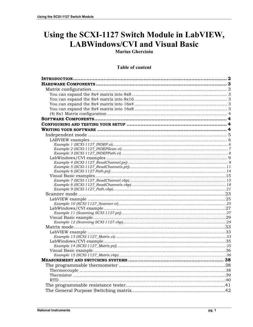
INTRODUCTION.................................................................................................... 2 HARDWARE COMPONENTS ..................................................................................... 3
Matrix configuration.............................................................................................. 3 You can expand the 8x4 matrix into 8x8 ....................................................................... 3 You can expand the 8x4 matrix into 8x16 ..................................................................... 3 You can expand the 8x4 matrix into 16x4 ..................................................................... 3 You can expand the 8x4 matrix into 16x8 ..................................................................... 3 (4) 8x1 Matrix configuration.......................................................................................... 4
SOFTWARE COMPONENTS...................................................................................... 4 CONFIGURING AND TESTING YOUR SETUP ................................................................. 4 WRITING YOUR SOFTWARE .................................................................................... 4
Independent mode ................................................................................................ 5 LABVIEW examples ...................................................................................................... 6
Example 1 (SCXI-1127_INDEP.vi)......................................................................................................... 6 Example 2 (SCXI-1127_INDEPScan.vi)................................................................................................. 7 Example 3 (SCXI-1127_INDEPPath.vi) ................................................................................................. 8
LabWindows/CVI examples .......................................................................................... 9 Example 4 (SCXI-1127_ReadChannel.prj) ........................................................................................... 9 Example 5 (SCXI-1127_ReadChannels.prj)........................................................................................ 11 Example 6 (SCXI-1127 Path.prj) ......................................................................................................... 14
Visual Basic examples .................................................................................................15 Example 7 (SCXI-1127_ReadChannel.vbp)........................................................................................ 15 Example 8 (SCXI-1127_ReadChannels.vbp) ...................................................................................... 18 Example 9 (SCXI-1127_Path.vbp)....................................................................................................... 21
Scanner mode ......................................................................................................23 LabVIEW example .......................................................................................................25
Example 10 (SCXI-1127_Scanner.vi).................................................................................................. 25 LabWindows/CVI example...........................................................................................27
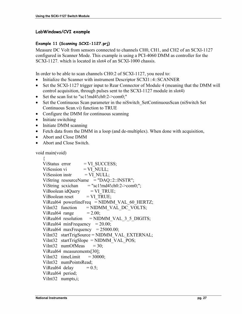
Example 11 (Scanning SCXI-1127.prj) ............................................................................................... 27 Visual Basic example...................................................................................................29
Example 12 (Scanning SCXI-1127.vbp).............................................................................................. 29 Matrix mode.........................................................................................................33
LabVIEW example .......................................................................................................33 Example 13 (SCXI-1127_Matrix.vi) ..................................................................................................... 33
LabWindows/CVI example...........................................................................................35 Example 14 (SCXI-1127_Matrix.prj) ................................................................................................... 35
Visual Basic example...................................................................................................36 Example 15 (SCXI-1127_Matrix.vbp).................................................................................................. 36
MEASUREMENT AND SWITCHING SYSTEMS .............................................................. 38 The programmable thermometer ..........................................................................38
Thermocouple .............................................................................................................38 Thermistor ..................................................................................................................39 RTD ............................................................................................................................40
The programmable resistance tester.....................................................................41 The General Purpose Switching matrix.................................................................42
Using the SCXI-1127 Switch Module
National Instruments pg. 2
Introduction With the general understanding of switching acquired, maybe from previous experience with switching devices, you identified the tests to be performed, selected the source and measure instruments, determined the setup of each test, and the switching topology(s) to be used. You selected as switching hardware the SCXI-1127 module. At this point you are ready to connect the system, test the configuration, write the software, verify the system, and run your tests. This application note describes a systematic approach to the implementation of an automatic test system using the SCXI-1127 and the NI-4060 DMM hardware from National Instruments. This application note comes with the several files. The LabVIEW files are: DMM & Switch Examples.llb SCXI-1127_INDEP.vi SCXI-1127_INDEPPath.vi SCXI-1127_INDEPScan.vi SCXI-1127_SCANNER.vi SCXI-1127_MATRIX.vi The following LabWindows/CVI files are: SCXI-1127_path.prj SCXI-1127_path.c SCXI-1127_ReadChannel.prj SCXI-1127_ReadChannel.c SCXI-1127_ReadChannels.prj SCXI-1127_ReadChannels.c Scanning SCXI-1127.prj Scanning SCXI-1127.c SCXI-1127_MATRIX.prj SCXI-1127_MATRIX.c The following visual basic files are: SCXI-1127_path.frm SCXI-1127_path.vbp SCXI-1127_path.vbw SCXI-1127_ReadChannel.frm SCXI-1127_ReadChannel.vbp SCXI-1127_ReadChannel.vbw SCXI-1127_ReadChannels.frm SCXI-1127_ReadChannels.vbp SCXI-1127_ReadChannels.vbw Scanning SCXI-1127.frm Scanning SCXI-1127.vbp Scanning SCXI-1127.vbw SCXI-1127_MATRIX.frm SCXI-1127_MATRIX.vbp SCXI-1127_MATRIX.vbw
Using the SCXI-1127 Switch Module
National Instruments pg. 3
Hardware Components • PCI-4060 plug-in board (or PXI-4060), • SCXI-1000, 4-slot (or SCXI-1001, 12-slot chassis), • SCXI-1127 module in slot4 (respective slot12, if SCXI-1001 chassis is used), • SCXI-1331 or SCXI-1332(for matrix configuration) connector blocs, • SCXI-1357 High Voltage Analog Buss (HVAB) connector, plugs into the SCXI-1000
(SCXI-1001) chassis, the back of SCXI-1127 in slot4(or slot12 for SCXI-1001) • Voltage cable HV8 toBan4, connects the HI/LO channel terminals of the DMM with the
HVAB, • Communications Trigger cable SH9MD-9MD connects the AUX I/O connector of the DMM
with the AUX IN connector of the HVAB. Matrix configuration
The SCXI-1127 module is a 32-channel differential high voltage multiplexer/matrix device. The SCXI-1331 terminal block allows for any configuration of the SCXI-1127 module, while the SCXI-1332 terminal block configures the SCX-1127 into an 8x4 matrix (8 columns and 4 rows).
You can expand the 8x4 matrix into 8x8 By setting up two SCXI-1127 modules, and connecting each column of one SCXI-1127 to the corresponding column on the other SCXI-1127, using Column Expansion Cables. In order to expand (or add) rows, you need to connect columns together.
You can expand the 8x4 matrix into 8x16 By setting up three SCXI-1127 modules, and connecting each column of module1, to the corresponding column of module2, and to the corresponding column of module3, using Column Expansion Cables.
You can expand the 8x4 matrix into 16x4 By setting up two SCXI-1127 modules, and connecting the four rows of one with the four rows of the other via either the SCXI-1357HV backplane, or outside the SCXI chassis by using the SCXI-1332 and Row Extension Cables, connecting each row of one SCXI-1127 to the corresponding row on the second SCXI-1127. In order to expand (or add) columns, you need to connect rows together, and the SCXI-1357HV backplane does that for you.
You can expand the 8x4 matrix into 16x8 By setting up four SCXI-1127 modules, and connecting - the four rows of module1 with the four rows of the module2, - the four rows of module3, with the four rows of module4 via either the SCXI-1357HV backplane , or using the SCXI-1332 and Row Extension Cables. - the four columns of module1 with the four columns of module3, - the four columns of the module2, with the four columns of module4 using the Column Extension Cables.
Using the SCXI-1127 Switch Module
National Instruments pg. 4
(4) 8x1 Matrix configuration If you want to have (4) 8x1 matrices for 1 SCXI-1127 Module you will need to use the SCXI-1331 terminal bloc. Each bank of 8 switches represents an 8x1 matrix. Bank1 for example contains switches ch0, ch1, ..., ch7. In independent mode, if you are connecting a differential signal to ch0 (ch0+ and ch0-), and then close switch ch0, this signal will be routed to OUT0 (OUT0+ and OUT0-). If you are also closing switch ch5, the same signal is retrievable from both ch5 (ch5+ and ch5-) and OUT0.
Software Components • LabVIEW, LabWindows/CVI, Visual Basic, or Visual C++, is installed in your computer. • NI-Switch 1.1 or higher version instrument driver needs to be installed. This installation will
install in your computer all necessary drivers needed to run the setup. During the installation, pay attention to the advanced button which allows you to verify which versions of other drivers like NI-DAQ, NI-IVI, NI-VISA and CVI-RTE are installed in your machine. The NI-Switch installer will install all these other drivers if necessary. The NI-Switch CD also contains an Example folder which will not be installed in your computer, but it is useful to know about later on when testing the setup.
• NI-DMM 1.1 or higher Configuring and testing your setup • Install NI-Switch, Shut Down your computer, install the hardware, reboot • run the Measurement & Automation Explorer and see that the NI-4060 board is listed under
Devices and Interfaces, as NI 4060 for PCI(Device 1). Test the board. • Highlight Devices and Interfaces, go to the Edit Menu and choose Insert, SCXI-1000 or
SCXI-1001 chassis. Insert also the SCXI-1127 module in slot4, and make sure that in the "Configuring SCXI-1127 Module in Chassis Slot 4" window you have Connected to Device1: NI 4060 for PCI, and the field "This device will control the chassis" is marked. Input channels can be configured on a per-channel basis. To configure the SCXI-1127 channels select the tab on the properties panel that is named “Channels”. Set the proper input mode configuration for the channels you are using.
• Test SCXI-1000 (or SCXI-1001) chassis. The chassis has been verified, is the message you should get if everything is set correctly.
Writing your software The SCXI-1127 module implements three basic switching topologies: - Independent mode - Scanner mode - Matrix mode Module topology is set in the initialization function or VI, by calling
Using the SCXI-1127 Switch Module
National Instruments pg. 5
niSwitch_Init ("SCXI1::4::SCANNER", VI_TRUE, VI_TRUE, ); (where the SCXI-1127 is in slot4) Note that you can dynamically choose or change the switching topology from inside the programming environment (LabVIEW, CVI, etc) by using the other initialization function or LabVIEW VI,
niSwitch_InitWithOptions ("DAQ::1::INSTR", VI_TRUE, VI_TRUE, "Simulate=0,DriverSetup=SCXI-1127 Mux", session); The option DriverSetup let's you dynamically change switching topology Other setting selections for: DriverSetup are "SCXI-1127 8x4 Matrix" and "SCXI-1127 Mux manual AB". You need to close the previous session with niSwitch_Close(session) before opening a new session with niSwitch_InitWithOptions. This is because the SCXI-1127 does not support several topologies in the same time.
Independent mode This is the basic switching topology because any topology can be built with the SCXI-1127 configured in Independent mode, if one is willing to complete the external wiring. Independent mode provides the user with individual control over any switch. The SCXI-1331 terminal block should be used. A unique session must be created for each module. The independent configuration uses the low level functions, such as niSwitch_SingleSwitchControl (niSwitch Control a Single Switch.vi). The switch names used in these low level functions refer to physical switches on the module. Before using the low level functions it is important to understand the switch naming conventions. Refer to Figure 2-26 on page 2-30 of the SCXI-1127 User Manual for more information. The SCXI-1127 is comprised of switches that are opened or closed based on the configuration of the software. These switches and their names are listed below.
Analog Bus Switches (ab0, ab1, ab2, ab3) These switches connect/disconnect the SCXI-1127 internal common bus to/from the high-voltage analog backplane. Channel Switches (ch0…ch31) These switches connect/disconnect the input signals to/from the SCXI-1127 internal common bus. Bank Connect Switches (bc01, bc02, bc23) The input of the SCXI-1127 consists of four 8 to 1 multiplexers. These multiplexers can be connected together by closing the bank connect switches. bc01 connects bank 0 to bank 1, bc02 connects bank 0 to bank 2, and bc23 connects bank 2 to bank 3. Cold Junction Sensor (cjtemp) The cold junction sensor on the SCXI-1331 terminal block can be accessed through the SCXI-1127. Closing this switch will connect the cold junction sensor to the internal common bus on the SCXI-1127.
Using the SCXI-1127 Switch Module
National Instruments pg. 6
For independent switch control, the program structure should be the following: - Open a session and Configure the SCXI-1127 module in independent mode by calling
niSwitch_Init ("SCXI1::4::INDEP", VI_TRUE, VI_TRUE, ); - Close/Open individual switches by using Low Level Control Functions like
niSwitch_SingeSwitchControl (or niSwitch_Control_a_Single_Switch.vi in LabVIEW)
- Close the session using niSwitch_Close(session)
LABVIEW examples
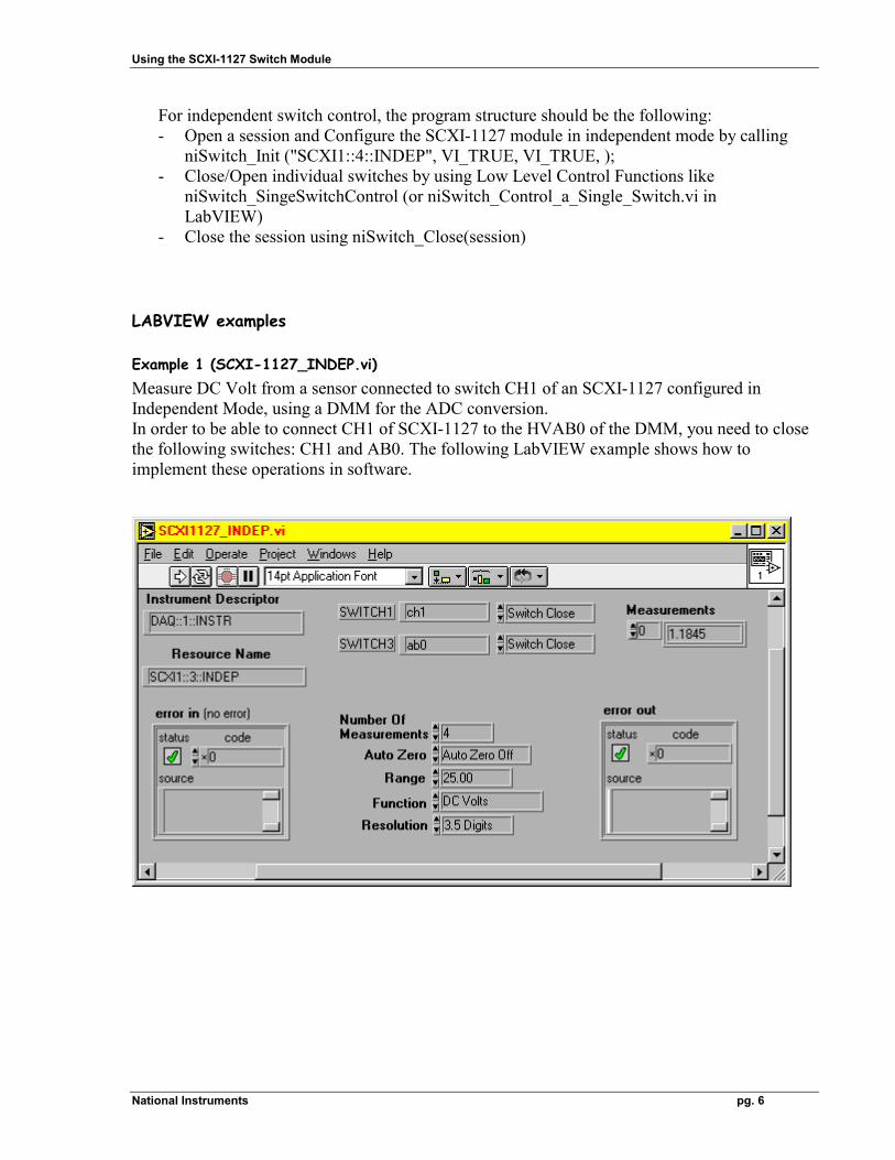
Example 1 (SCXI-1127_INDEP.vi) Measure DC Volt from a sensor connected to switch CH1 of an SCXI-1127 configured in Independent Mode, using a DMM for the ADC conversion. In order to be able to connect CH1 of SCXI-1127 to the HVAB0 of the DMM, you need to close the following switches: CH1 and AB0. The following LabVIEW example shows how to implement these operations in software.
Using the SCXI-1127 Switch Module
National Instruments pg. 7
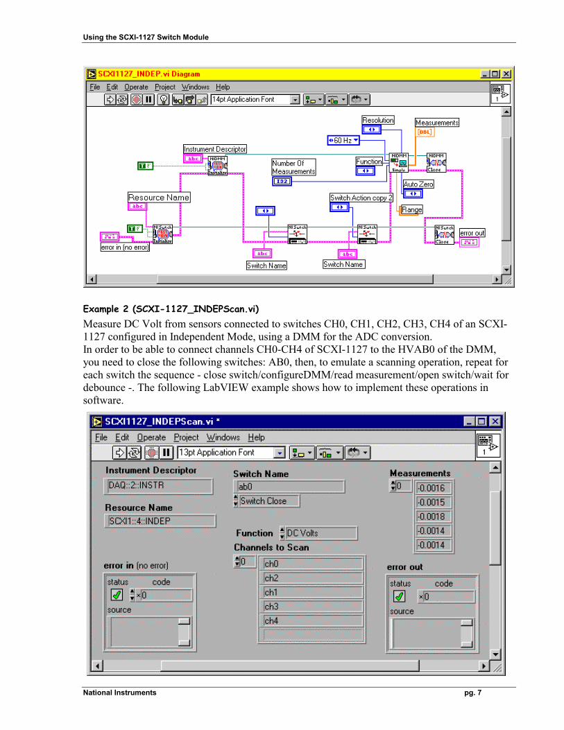
Example 2 (SCXI-1127_INDEPScan.vi) Measure DC Volt from sensors connected to switches CH0, CH1, CH2, CH3, CH4 of an SCXI-1127 configured in Independent Mode, using a DMM for the ADC conversion. In order to be able to connect channels CH0-CH4 of SCXI-1127 to the HVAB0 of the DMM, you need to close the following switches: AB0, then, to emulate a scanning operation, repeat for each switch the sequence - close switch/configureDMM/read measurement/open switch/wait for debounce -. The following LabVIEW example shows how to implement these operations in software.
Using the SCXI-1127 Switch Module
National Instruments pg. 8
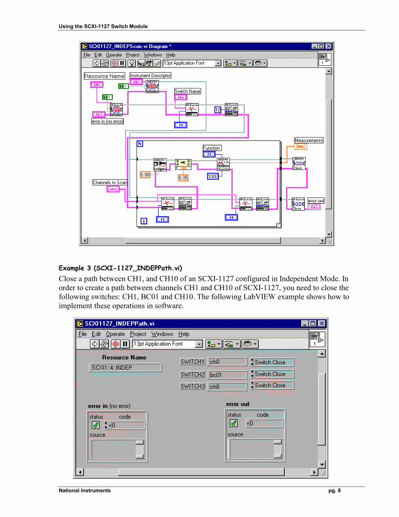
Example 3 (SCXI-1127_INDEPPath.vi) Close a path between CH1, and CH10 of an SCXI-1127 configured in Independent Mode. In order to create a path between channels CH1 and CH10 of SCXI-1127, you need to close the following switches: CH1, BC01 and CH10. The following LabVIEW example shows how to implement these operations in software.
Using the SCXI-1127 Switch Module
National Instruments pg. 9
LabWindows/CVI examples
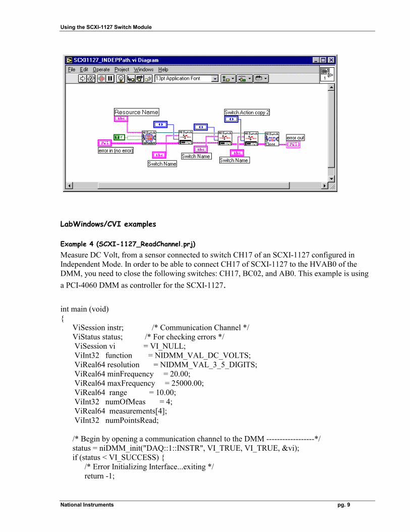
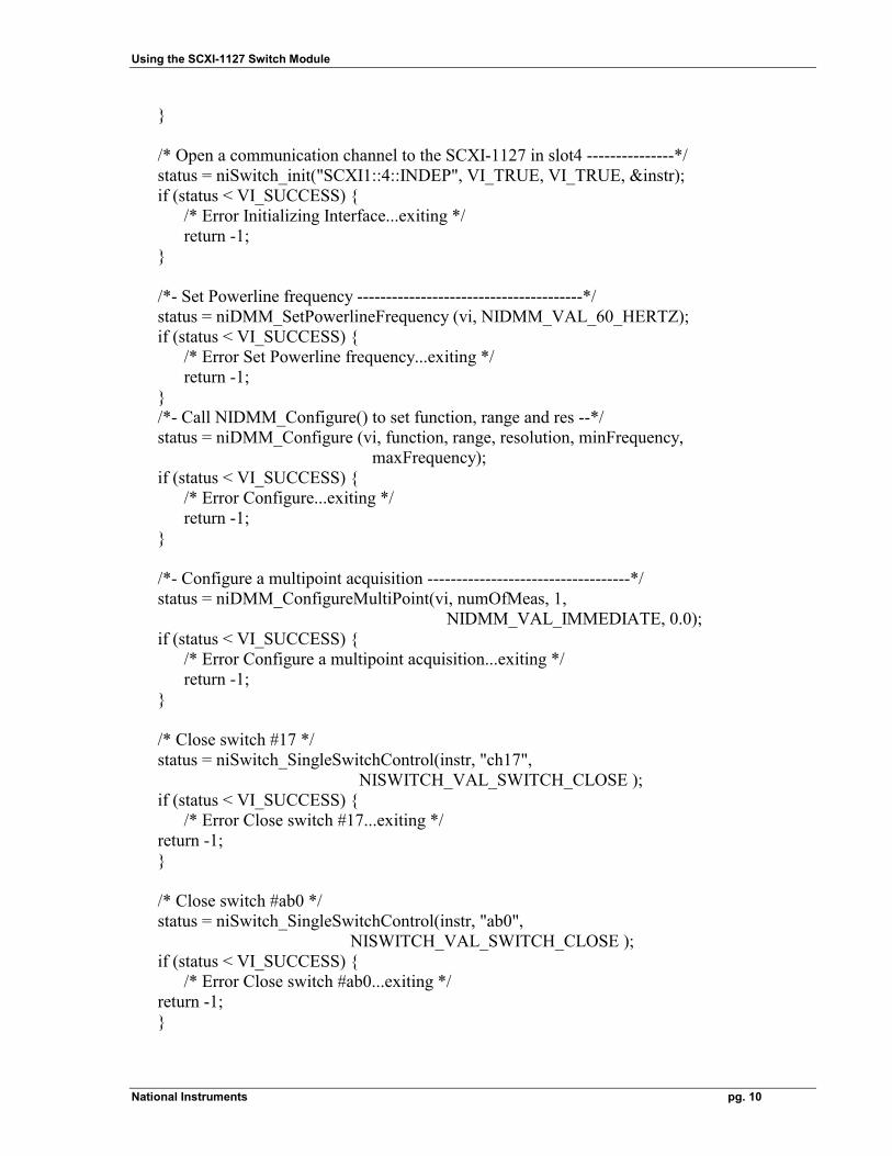
Example 4 (SCXI-1127_ReadChannel.prj) Measure DC Volt, from a sensor connected to switch CH17 of an SCXI-1127 configured in Independent Mode. In order to be able to connect CH17 of SCXI-1127 to the HVAB0 of the DMM, you need to close the following switches: CH17, BC02, and AB0. This example is using a PCI-4060 DMM as controller for the SCXI-1127. int main (void) { ViSession instr; /* Communication Channel */ ViStatus status; /* For checking errors */ ViSession vi = VI_NULL; ViInt32 function = NIDMM_VAL_DC_VOLTS; ViReal64 resolution = NIDMM_VAL_3_5_DIGITS; ViReal64 minFrequency = 20.00; ViReal64 maxFrequency = 25000.00; ViReal64 range = 10.00; ViInt32 numOfMeas = 4; ViReal64 measurements[4]; ViInt32 numPointsRead; /* Begin by opening a communication channel to the DMM ------------------*/ status = niDMM_init("DAQ::1::INSTR", VI_TRUE, VI_TRUE, &vi); if (status < VI_SUCCESS) { /* Error Initializing Interface...exiting */ return -1;
Using the SCXI-1127 Switch Module
National Instruments pg. 10
} /* Open a communication channel to the SCXI-1127 in slot4 ---------------*/ status = niSwitch_init("SCXI1::4::INDEP", VI_TRUE, VI_TRUE, &instr); if (status < VI_SUCCESS) { /* Error Initializing Interface...exiting */ return -1; } /*- Set Powerline frequency ---------------------------------------*/ status = niDMM_SetPowerlineFrequency (vi, NIDMM_VAL_60_HERTZ); if (status < VI_SUCCESS) { /* Error Set Powerline frequency...exiting */ return -1; } /*- Call NIDMM_Configure() to set function, range and res --*/ status = niDMM_Configure (vi, function, range, resolution, minFrequency, maxFrequency); if (status < VI_SUCCESS) { /* Error Configure...exiting */ return -1; } /*- Configure a multipoint acquisition -----------------------------------*/ status = niDMM_ConfigureMultiPoint(vi, numOfMeas, 1, NIDMM_VAL_IMMEDIATE, 0.0); if (status < VI_SUCCESS) { /* Error Configure a multipoint acquisition...exiting */ return -1; } /* Close switch #17 */ status = niSwitch_SingleSwitchControl(instr, "ch17", NISWITCH_VAL_SWITCH_CLOSE ); if (status < VI_SUCCESS) { /* Error Close switch #17...exiting */ return -1; } /* Close switch #ab0 */ status = niSwitch_SingleSwitchControl(instr, "ab0", NISWITCH_VAL_SWITCH_CLOSE ); if (status < VI_SUCCESS) { /* Error Close switch #ab0...exiting */ return -1; }
Using the SCXI-1127 Switch Module
National Instruments pg. 11
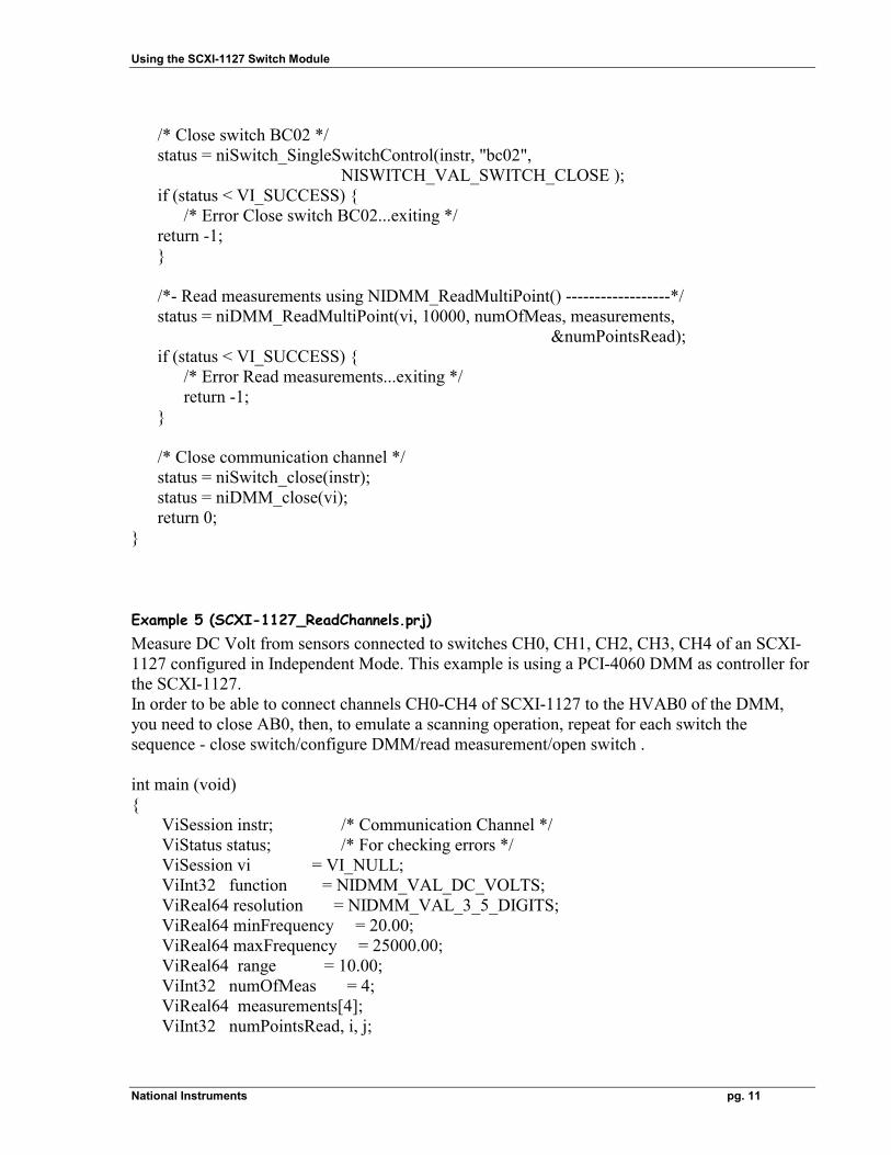
/* Close switch BC02 */ status = niSwitch_SingleSwitchControl(instr, "bc02", NISWITCH_VAL_SWITCH_CLOSE ); if (status < VI_SUCCESS) { /* Error Close switch BC02...exiting */ return -1; } /*- Read measurements using NIDMM_ReadMultiPoint() ------------------*/ status = niDMM_ReadMultiPoint(vi, 10000, numOfMeas, measurements, &numPointsRead); if (status < VI_SUCCESS) { /* Error Read measurements...exiting */ return -1; } /* Close communication channel */ status = niSwitch_close(instr); status = niDMM_close(vi); return 0; }
Example 5 (SCXI-1127_ReadChannels.prj) Measure DC Volt from sensors connected to switches CH0, CH1, CH2, CH3, CH4 of an SCXI-1127 configured in Independent Mode. This example is using a PCI-4060 DMM as controller for the SCXI-1127. In order to be able to connect channels CH0-CH4 of SCXI-1127 to the HVAB0 of the DMM, you need to close AB0, then, to emulate a scanning operation, repeat for each switch the sequence - close switch/configure DMM/read measurement/open switch . int main (void) { ViSession instr; /* Communication Channel */ ViStatus status; /* For checking errors */ ViSession vi = VI_NULL; ViInt32 function = NIDMM_VAL_DC_VOLTS; ViReal64 resolution = NIDMM_VAL_3_5_DIGITS; ViReal64 minFrequency = 20.00; ViReal64 maxFrequency = 25000.00; ViReal64 range = 10.00; ViInt32 numOfMeas = 4; ViReal64 measurements[4]; ViInt32 numPointsRead, i, j;
Using the SCXI-1127 Switch Module
National Instruments pg. 12
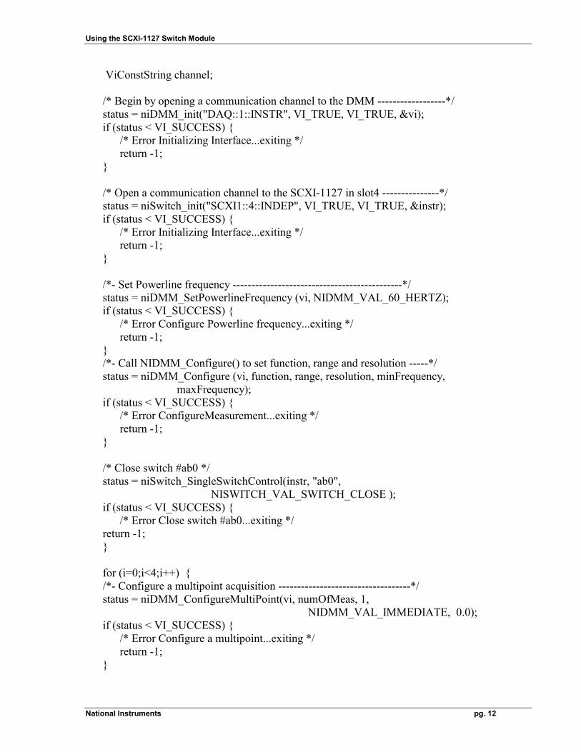
ViConstString channel; /* Begin by opening a communication channel to the DMM ------------------*/ status = niDMM_init("DAQ::1::INSTR", VI_TRUE, VI_TRUE, &vi); if (status < VI_SUCCESS) { /* Error Initializing Interface...exiting */ return -1; } /* Open a communication channel to the SCXI-1127 in slot4 ---------------*/ status = niSwitch_init("SCXI1::4::INDEP", VI_TRUE, VI_TRUE, &instr); if (status < VI_SUCCESS) { /* Error Initializing Interface...exiting */ return -1; } /*- Set Powerline frequency ---------------------------------------------*/ status = niDMM_SetPowerlineFrequency (vi, NIDMM_VAL_60_HERTZ); if (status < VI_SUCCESS) { /* Error Configure Powerline frequency...exiting */ return -1; } /*- Call NIDMM_Configure() to set function, range and resolution -----*/ status = niDMM_Configure (vi, function, range, resolution, minFrequency, maxFrequency); if (status < VI_SUCCESS) { /* Error ConfigureMeasurement...exiting */ return -1; } /* Close switch #ab0 */ status = niSwitch_SingleSwitchControl(instr, "ab0", NISWITCH_VAL_SWITCH_CLOSE ); if (status < VI_SUCCESS) { /* Error Close switch #ab0...exiting */ return -1; } for (i=0;i<4;i++) { /*- Configure a multipoint acquisition -----------------------------------*/ status = niDMM_ConfigureMultiPoint(vi, numOfMeas, 1, NIDMM_VAL_IMMEDIATE, 0.0); if (status < VI_SUCCESS) { /* Error Configure a multipoint...exiting */ return -1; }
Using the SCXI-1127 Switch Module
National Instruments pg. 13
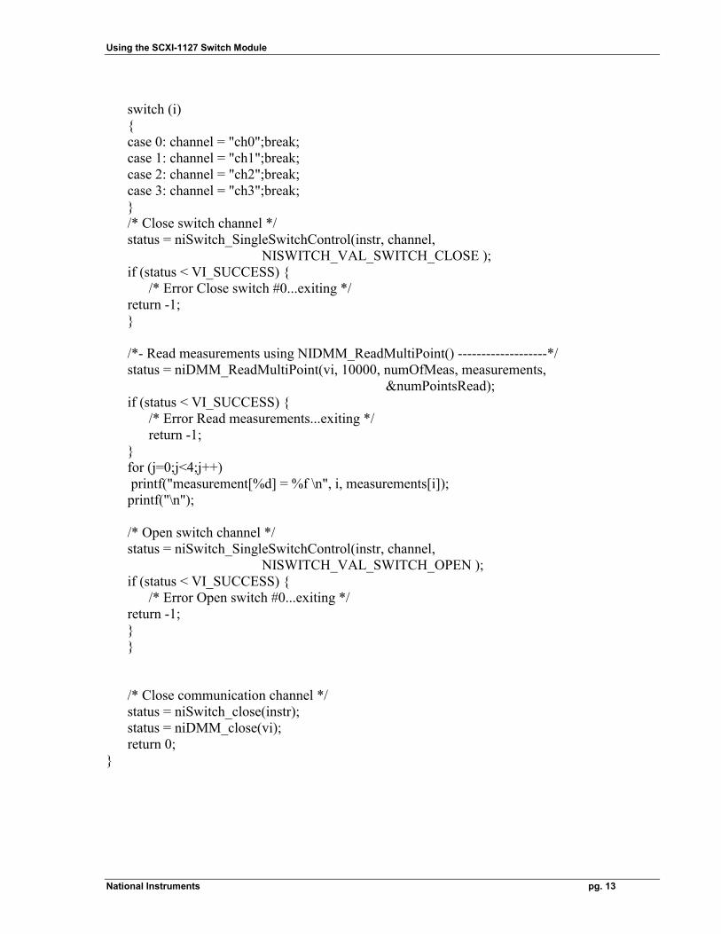
switch (i) { case 0: channel = "ch0";break; case 1: channel = "ch1";break; case 2: channel = "ch2";break; case 3: channel = "ch3";break; } /* Close switch channel */ status = niSwitch_SingleSwitchControl(instr, channel, NISWITCH_VAL_SWITCH_CLOSE ); if (status < VI_SUCCESS) { /* Error Close switch #0...exiting */ return -1; } /*- Read measurements using NIDMM_ReadMultiPoint() -------------------*/ status = niDMM_ReadMultiPoint(vi, 10000, numOfMeas, measurements, &numPointsRead); if (status < VI_SUCCESS) { /* Error Read measurements...exiting */ return -1; } for (j=0;j<4;j++) printf("measurement[%d] = %f \n", i, measurements[i]); printf("\n"); /* Open switch channel */ status = niSwitch_SingleSwitchControl(instr, channel, NISWITCH_VAL_SWITCH_OPEN ); if (status < VI_SUCCESS) { /* Error Open switch #0...exiting */ return -1; } } /* Close communication channel */ status = niSwitch_close(instr); status = niDMM_close(vi); return 0; }
Using the SCXI-1127 Switch Module
National Instruments pg. 14
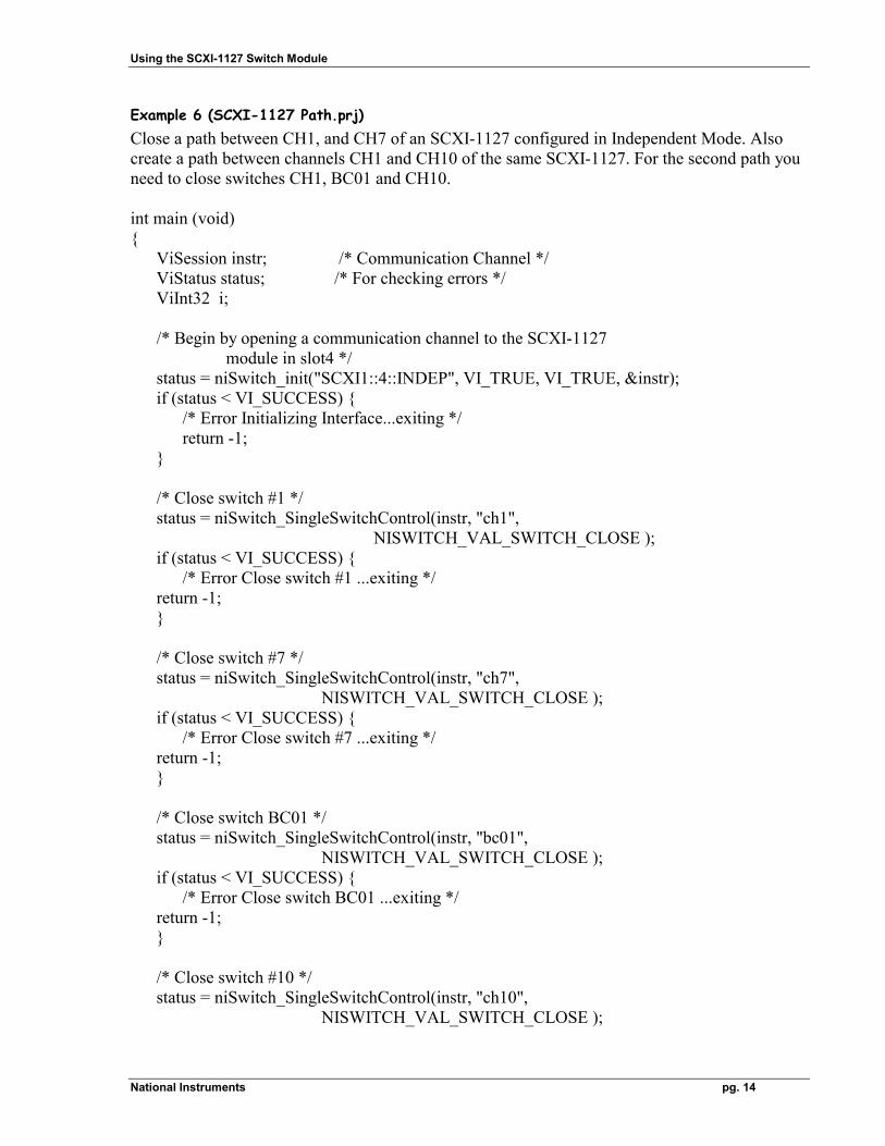
Example 6 (SCXI-1127 Path.prj) Close a path between CH1, and CH7 of an SCXI-1127 configured in Independent Mode. Also create a path between channels CH1 and CH10 of the same SCXI-1127. For the second path you need to close switches CH1, BC01 and CH10. int main (void) { ViSession instr; /* Communication Channel */ ViStatus status; /* For checking errors */ ViInt32 i; /* Begin by opening a communication channel to the SCXI-1127 module in slot4 */ status = niSwitch_init("SCXI1::4::INDEP", VI_TRUE, VI_TRUE, &instr); if (status < VI_SUCCESS) { /* Error Initializing Interface...exiting */ return -1; } /* Close switch #1 */ status = niSwitch_SingleSwitchControl(instr, "ch1", NISWITCH_VAL_SWITCH_CLOSE ); if (status < VI_SUCCESS) { /* Error Close switch #1 ...exiting */ return -1; } /* Close switch #7 */ status = niSwitch_SingleSwitchControl(instr, "ch7", NISWITCH_VAL_SWITCH_CLOSE ); if (status < VI_SUCCESS) { /* Error Close switch #7 ...exiting */ return -1; } /* Close switch BC01 */ status = niSwitch_SingleSwitchControl(instr, "bc01", NISWITCH_VAL_SWITCH_CLOSE ); if (status < VI_SUCCESS) { /* Error Close switch BC01 ...exiting */ return -1; } /* Close switch #10 */ status = niSwitch_SingleSwitchControl(instr, "ch10", NISWITCH_VAL_SWITCH_CLOSE );
Using the SCXI-1127 Switch Module
National Instruments pg. 15
if (status < VI_SUCCESS) { /* Error Close switch #10 ...exiting */ return -1; } /* Close communication channel */ status = niSwitch_close(instr); return 0; }
Visual Basic examples
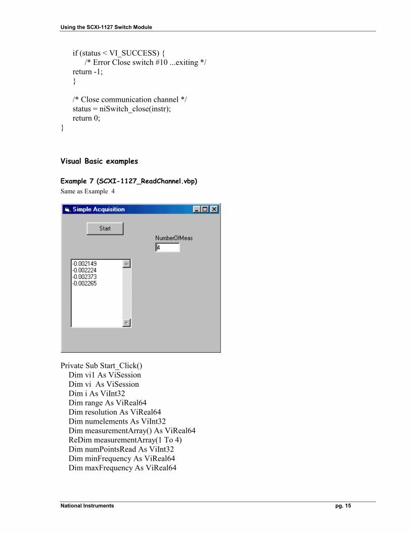
Example 7 (SCXI-1127_ReadChannel.vbp) Same as Example 4
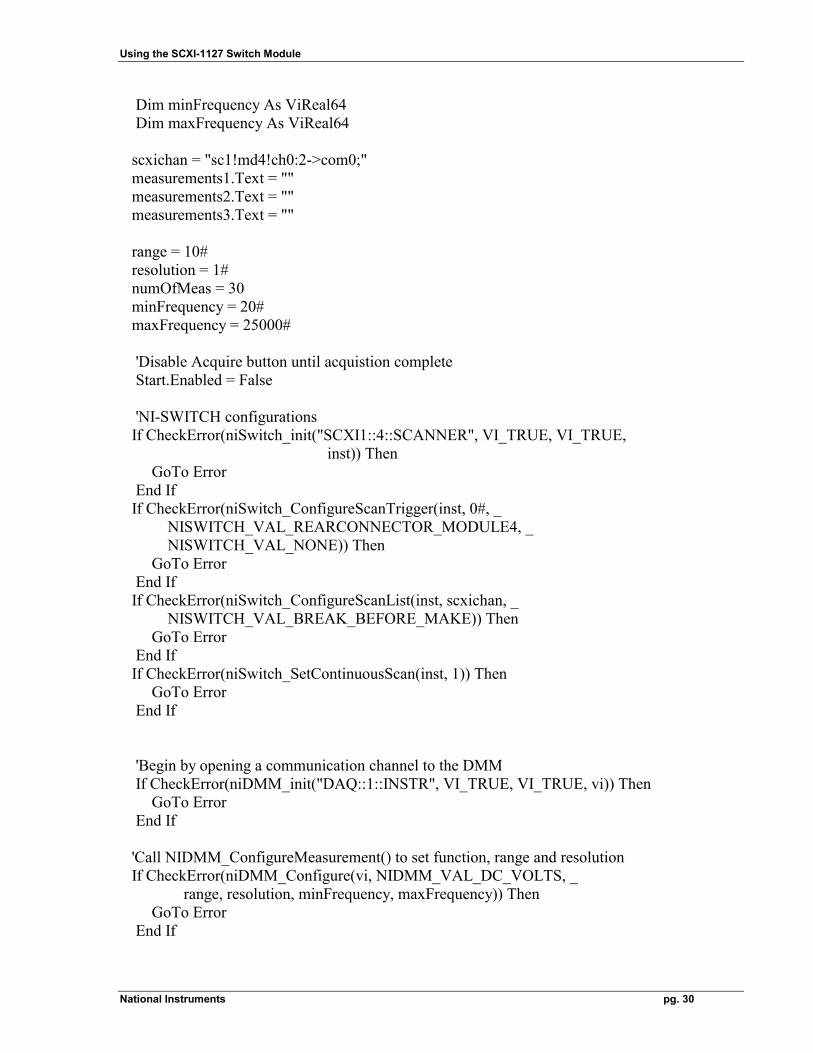
Private Sub Start_Click() Dim vi1 As ViSession Dim vi As ViSession Dim i As ViInt32 Dim range As ViReal64 Dim resolution As ViReal64 Dim numelements As ViInt32 Dim measurementArray() As ViReal64 ReDim measurementArray(1 To 4) Dim numPointsRead As ViInt32 Dim minFrequency As ViReal64 Dim maxFrequency As ViReal64
Using the SCXI-1127 Switch Module
National Instruments pg. 16
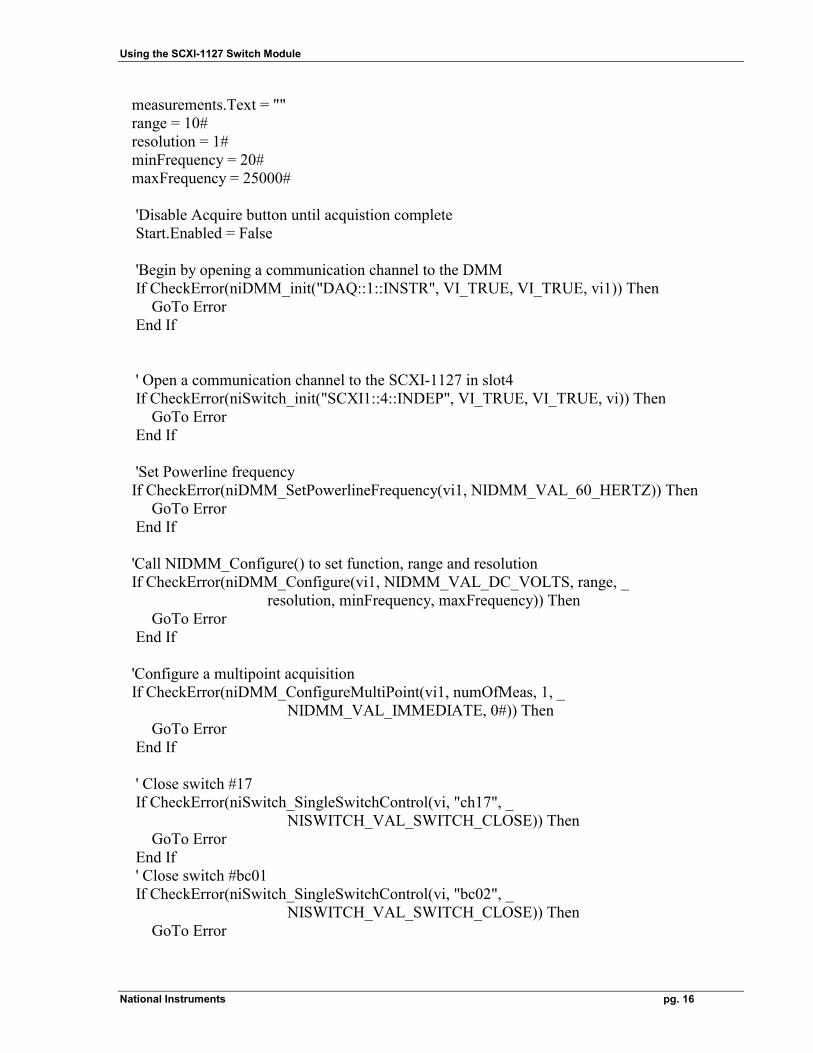
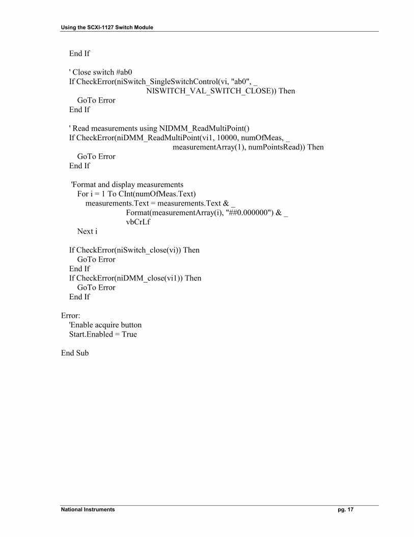
measurements.Text = "" range = 10# resolution = 1# minFrequency = 20# maxFrequency = 25000# 'Disable Acquire button until acquistion complete Start.Enabled = False 'Begin by opening a communication channel to the DMM If CheckError(niDMM_init("DAQ::1::INSTR", VI_TRUE, VI_TRUE, vi1)) Then GoTo Error End If ' Open a communication channel to the SCXI-1127 in slot4 If CheckError(niSwitch_init("SCXI1::4::INDEP", VI_TRUE, VI_TRUE, vi)) Then GoTo Error End If 'Set Powerline frequency If CheckError(niDMM_SetPowerlineFrequency(vi1, NIDMM_VAL_60_HERTZ)) Then GoTo Error End If 'Call NIDMM_Configure() to set function, range and resolution If CheckError(niDMM_Configure(vi1, NIDMM_VAL_DC_VOLTS, range, _ resolution, minFrequency, maxFrequency)) Then GoTo Error End If 'Configure a multipoint acquisition If CheckError(niDMM_ConfigureMultiPoint(vi1, numOfMeas, 1, _ NIDMM_VAL_IMMEDIATE, 0#)) Then GoTo Error End If ' Close switch #17 If CheckError(niSwitch_SingleSwitchControl(vi, "ch17", _ NISWITCH_VAL_SWITCH_CLOSE)) Then GoTo Error End If ' Close switch #bc01 If CheckError(niSwitch_SingleSwitchControl(vi, "bc02", _ NISWITCH_VAL_SWITCH_CLOSE)) Then GoTo Error
Using the SCXI-1127 Switch Module
National Instruments pg. 17
End If ' Close switch #ab0 If CheckError(niSwitch_SingleSwitchControl(vi, "ab0", _ NISWITCH_VAL_SWITCH_CLOSE)) Then GoTo Error End If ' Read measurements using NIDMM_ReadMultiPoint() If CheckError(niDMM_ReadMultiPoint(vi1, 10000, numOfMeas, _ measurementArray(1), numPointsRead)) Then GoTo Error End If 'Format and display measurements For i = 1 To CInt(numOfMeas.Text) measurements.Text = measurements.Text & _ Format(measurementArray(i), "##0.000000") & _ vbCrLf Next i If CheckError(niSwitch_close(vi)) Then GoTo Error End If If CheckError(niDMM_close(vi1)) Then GoTo Error End If Error: 'Enable acquire button Start.Enabled = True End Sub
Using the SCXI-1127 Switch Module
National Instruments pg. 18
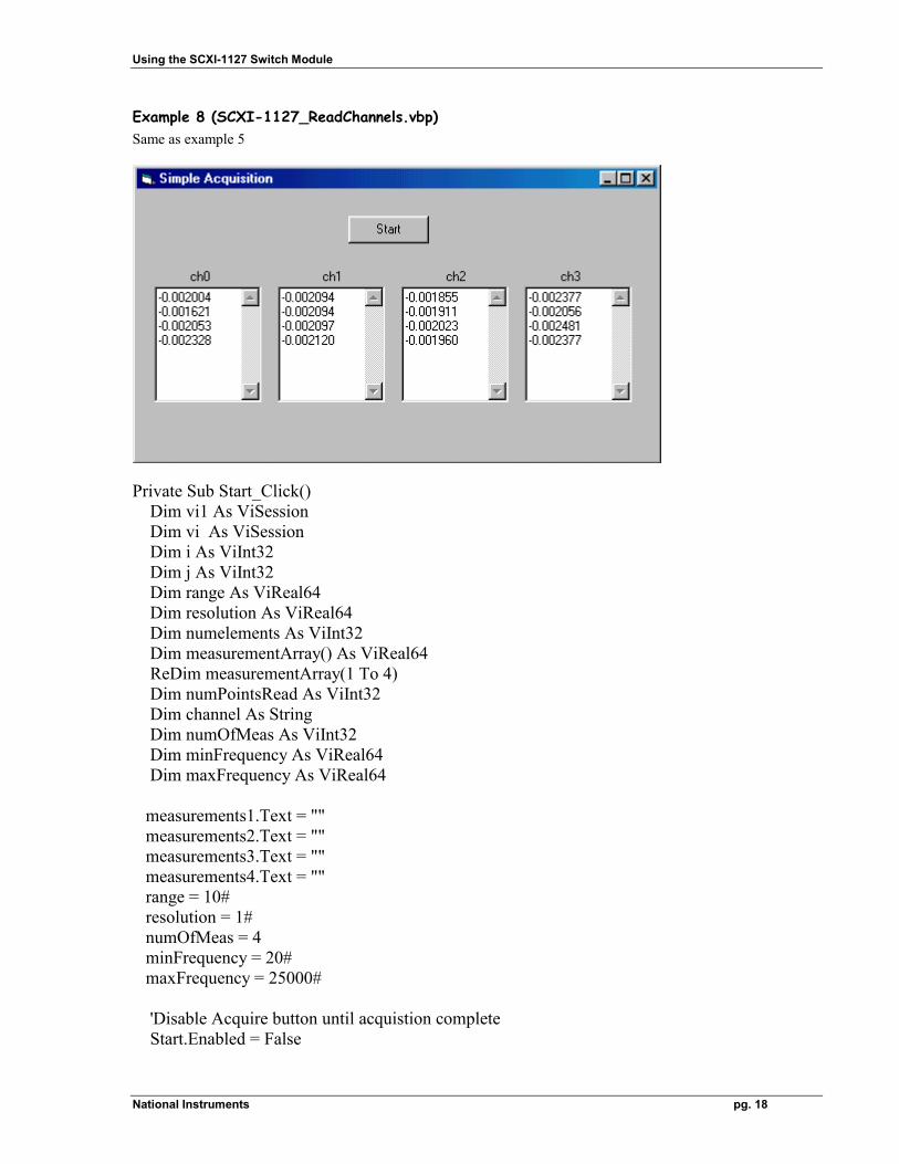
Example 8 (SCXI-1127_ReadChannels.vbp) Same as example 5
Private Sub Start_Click() Dim vi1 As ViSession Dim vi As ViSession Dim i As ViInt32 Dim j As ViInt32 Dim range As ViReal64 Dim resolution As ViReal64 Dim numelements As ViInt32 Dim measurementArray() As ViReal64 ReDim measurementArray(1 To 4) Dim numPointsRead As ViInt32 Dim channel As String Dim numOfMeas As ViInt32 Dim minFrequency As ViReal64 Dim maxFrequency As ViReal64 measurements1.Text = "" measurements2.Text = "" measurements3.Text = "" measurements4.Text = "" range = 10# resolution = 1# numOfMeas = 4 minFrequency = 20# maxFrequency = 25000# 'Disable Acquire button until acquistion complete Start.Enabled = False
Using the SCXI-1127 Switch Module
National Instruments pg. 19
'Begin by opening a communication channel to the DMM If CheckError(niDMM_init("DAQ::1::INSTR", VI_TRUE, VI_TRUE, vi1)) Then GoTo Error End If ' Open a communication channel to the SCXI-1127 in slot4 If CheckError(niSwitch_init("SCXI1::4::INDEP", VI_TRUE, VI_TRUE, vi)) Then GoTo Error End If 'Configure Powerline frequency If CheckError(niDMM_SetPowerlineFrequency(vi1, NIDMM_VAL_60_HERTZ)) Then GoTo Error End If 'Call NIDMM_Configure() to set function, range and resolution If CheckError(niDMM_Configure(vi1, NIDMM_VAL_DC_VOLTS, range, _ resolution, minFrequency, maxFrequency)) Then GoTo Error End If ' Close switch #ab0 If CheckError(niSwitch_SingleSwitchControl(vi, "ab0", _ NISWITCH_VAL_SWITCH_CLOSE)) Then GoTo Error End If For i = 1 To 4 'Configure a multipoint acquisition If CheckError(niDMM_ConfigureMultiPoint(vi1, numOfMeas, 1, _ NIDMM_VAL_IMMEDIATE, 0#)) Then GoTo Error End If Select Case (i) Case 1: channel = "ch0" Case 2: channel = "ch1" Case 3: channel = "ch2" Case 4: channel = "ch4" End Select ' Close switch channel If CheckError(niSwitch_SingleSwitchControl(vi, channel, _ NISWITCH_VAL_SWITCH_CLOSE)) Then
Using the SCXI-1127 Switch Module
National Instruments pg. 20
GoTo Error End If ' Read measurements using NIDMM_ReadMultiPoint() If CheckError(niDMM_ReadMultiPoint(vi1, 10000, numOfMeas, _ measurementArray(1), _ numPointsRead)) Then GoTo Error End If 'Format and display measurements Select Case (i) Case 1: For j = 1 To numOfMeas measurements1.Text = measurements1.Text & _ Format(measurementArray(j), "##0.000000") & _ vbCrLf Next j Case 2: For j = 1 To numOfMeas measurements2.Text = measurements2.Text & _ Format(measurementArray(j), "##0.000000") & _ vbCrLf Next j Case 3: For j = 1 To numOfMeas measurements3.Text = measurements3.Text & _ Format(measurementArray(j), "##0.000000") & _ vbCrLf Next j Case 4: For j = 1 To numOfMeas measurements4.Text = measurements4.Text & _ Format(measurementArray(j), "##0.000000") & _ vbCrLf Next j End Select ' Open switch channel If CheckError(niSwitch_SingleSwitchControl(vi, channel, _ NISWITCH_VAL_SWITCH_OPEN)) Then GoTo Error End If Next i If CheckError(niSwitch_close(vi)) Then GoTo Error End If If CheckError(niDMM_close(vi1)) Then GoTo Error End If
Using the SCXI-1127 Switch Module
National Instruments pg. 21
Error: 'Enable acquire button Start.Enabled = True End Sub
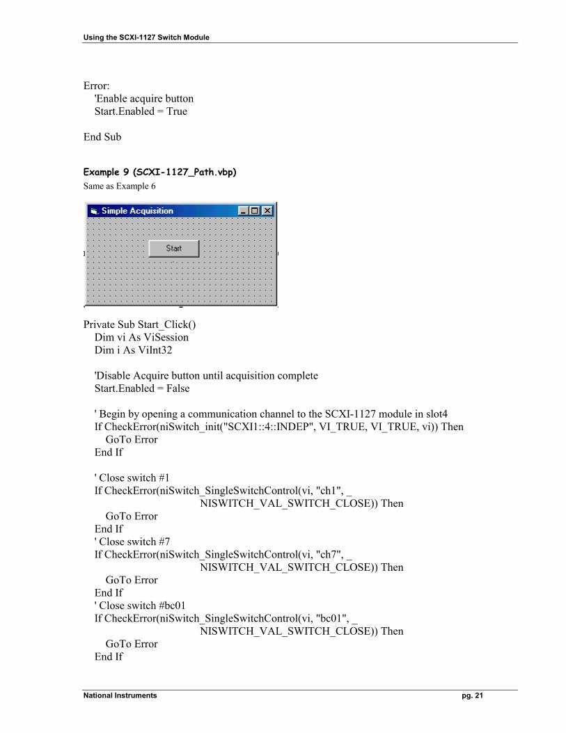
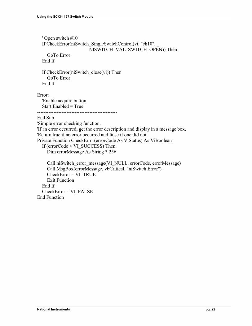
Example 9 (SCXI-1127_Path.vbp) Same as Example 6
Private Sub Start_Click() Dim vi As ViSession Dim i As ViInt32 'Disable Acquire button until acquisition complete Start.Enabled = False ' Begin by opening a communication channel to the SCXI-1127 module in slot4 If CheckError(niSwitch_init("SCXI1::4::INDEP", VI_TRUE, VI_TRUE, vi)) Then GoTo Error End If ' Close switch #1 If CheckError(niSwitch_SingleSwitchControl(vi, "ch1", _ NISWITCH_VAL_SWITCH_CLOSE)) Then GoTo Error End If ' Close switch #7 If CheckError(niSwitch_SingleSwitchControl(vi, "ch7", _ NISWITCH_VAL_SWITCH_CLOSE)) Then GoTo Error End If ' Close switch #bc01 If CheckError(niSwitch_SingleSwitchControl(vi, "bc01", _ NISWITCH_VAL_SWITCH_CLOSE)) Then GoTo Error End If
Using the SCXI-1127 Switch Module
National Instruments pg. 22
' Open switch #10 If CheckError(niSwitch_SingleSwitchControl(vi, "ch10", _ NISWITCH_VAL_SWITCH_OPEN)) Then GoTo Error End If If CheckError(niSwitch_close(vi)) Then GoTo Error End If Error: 'Enable acquire button Start.Enabled = True ------------------------------------------------- End Sub 'Simple error checking function. 'If an error occurred, get the error description and display in a message box. 'Return true if an error occurred and false if one did not. Private Function CheckError(errorCode As ViStatus) As ViBoolean If (errorCode < VI_SUCCESS) Then Dim errorMessage As String * 256 Call niSwitch_error_message(VI_NULL, errorCode, errorMessage) Call MsgBox(errorMessage, vbCritical, "niSwitch Error") CheckError = VI_TRUE Exit Function End If CheckError = VI_FALSE End Function
Using the SCXI-1127 Switch Module
National Instruments pg. 23
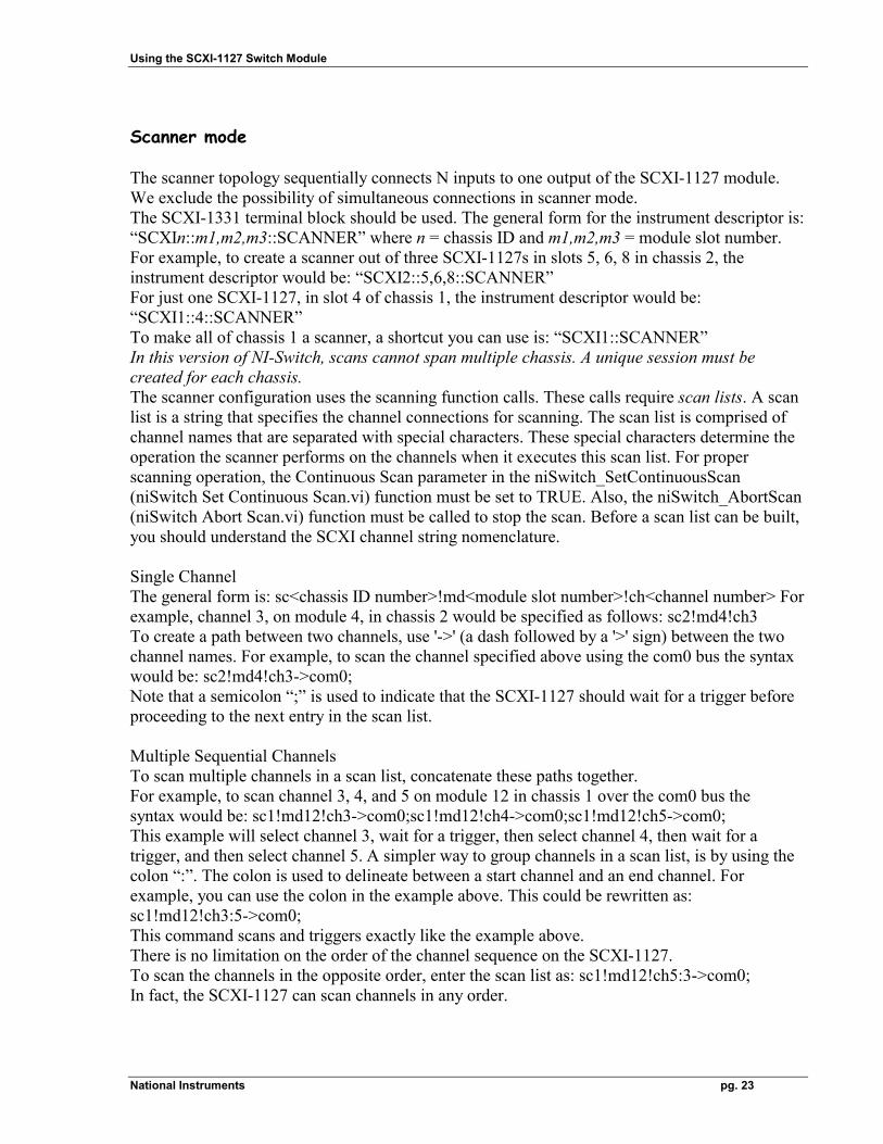
Scanner mode The scanner topology sequentially connects N inputs to one output of the SCXI-1127 module. We exclude the possibility of simultaneous connections in scanner mode. The SCXI-1331 terminal block should be used. The general form for the instrument descriptor is: “SCXIn::m1,m2,m3::SCANNER” where n = chassis ID and m1,m2,m3 = module slot number. For example, to create a scanner out of three SCXI-1127s in slots 5, 6, 8 in chassis 2, the instrument descriptor would be: “SCXI2::5,6,8::SCANNER” For just one SCXI-1127, in slot 4 of chassis 1, the instrument descriptor would be: “SCXI1::4::SCANNER” To make all of chassis 1 a scanner, a shortcut you can use is: “SCXI1::SCANNER” In this version of NI-Switch, scans cannot span multiple chassis. A unique session must be created for each chassis. The scanner configuration uses the scanning function calls. These calls require scan lists. A scan list is a string that specifies the channel connections for scanning. The scan list is comprised of channel names that are separated with special characters. These special characters determine the operation the scanner performs on the channels when it executes this scan list. For proper scanning operation, the Continuous Scan parameter in the niSwitch_SetContinuousScan (niSwitch Set Continuous Scan.vi) function must be set to TRUE. Also, the niSwitch_AbortScan (niSwitch Abort Scan.vi) function must be called to stop the scan. Before a scan list can be built, you should understand the SCXI channel string nomenclature. Single Channel The general form is: sc<chassis ID number>!md<module slot number>!ch<channel number> For example, channel 3, on module 4, in chassis 2 would be specified as follows: sc2!md4!ch3 To create a path between two channels, use '->' (a dash followed by a '>' sign) between the two channel names. For example, to scan the channel specified above using the com0 bus the syntax would be: sc2!md4!ch3->com0; Note that a semicolon “;” is used to indicate that the SCXI-1127 should wait for a trigger before proceeding to the next entry in the scan list. Multiple Sequential Channels To scan multiple channels in a scan list, concatenate these paths together. For example, to scan channel 3, 4, and 5 on module 12 in chassis 1 over the com0 bus the syntax would be: sc1!md12!ch3->com0;sc1!md12!ch4->com0;sc1!md12!ch5->com0; This example will select channel 3, wait for a trigger, then select channel 4, then wait for a trigger, and then select channel 5. A simpler way to group channels in a scan list, is by using the colon “:”. The colon is used to delineate between a start channel and an end channel. For example, you can use the colon in the example above. This could be rewritten as: sc1!md12!ch3:5->com0; This command scans and triggers exactly like the example above. There is no limitation on the order of the channel sequence on the SCXI-1127. To scan the channels in the opposite order, enter the scan list as: sc1!md12!ch5:3->com0; In fact, the SCXI-1127 can scan channels in any order.
Using the SCXI-1127 Switch Module
National Instruments pg. 24
Multiple Random Channels For example, to scan channel 8 on module 2, then channel 4 on module 4, and channel 12 on module 3 in chassis 1 over the com0 bus the syntax would be: sc1!md2!ch8->com0; sc1!md4!ch4->com0; sc1!md3!ch12->com0; This example will select channel 8 (module 2), wait for a trigger, then select channel 4 (module 4), then wait for a trigger, and then select channel 12 (module 3). Cold Junction Sensor Channel The SCXI-1331 contains a cold-junction temperature sensor. This sensor connects to a special channel on the SCXI-1127 dedicated to measuring the ambient temperature of the terminal block. This channel is used when measuring thermocouples. This channel is always scanned as a two-wire channel. You can include the CJS channel at any position in the list with any number of repetitions. For example, to scan the cold junction sensor, and channels 3, 8, and 5 on module 12 in chassis1 over the com0 bus the syntax would be: sc1!md12!cjtemp->com0;
sc1!md12!ch3->com0; sc1!md12!ch8->com0; sc1!md12!ch5->com0;
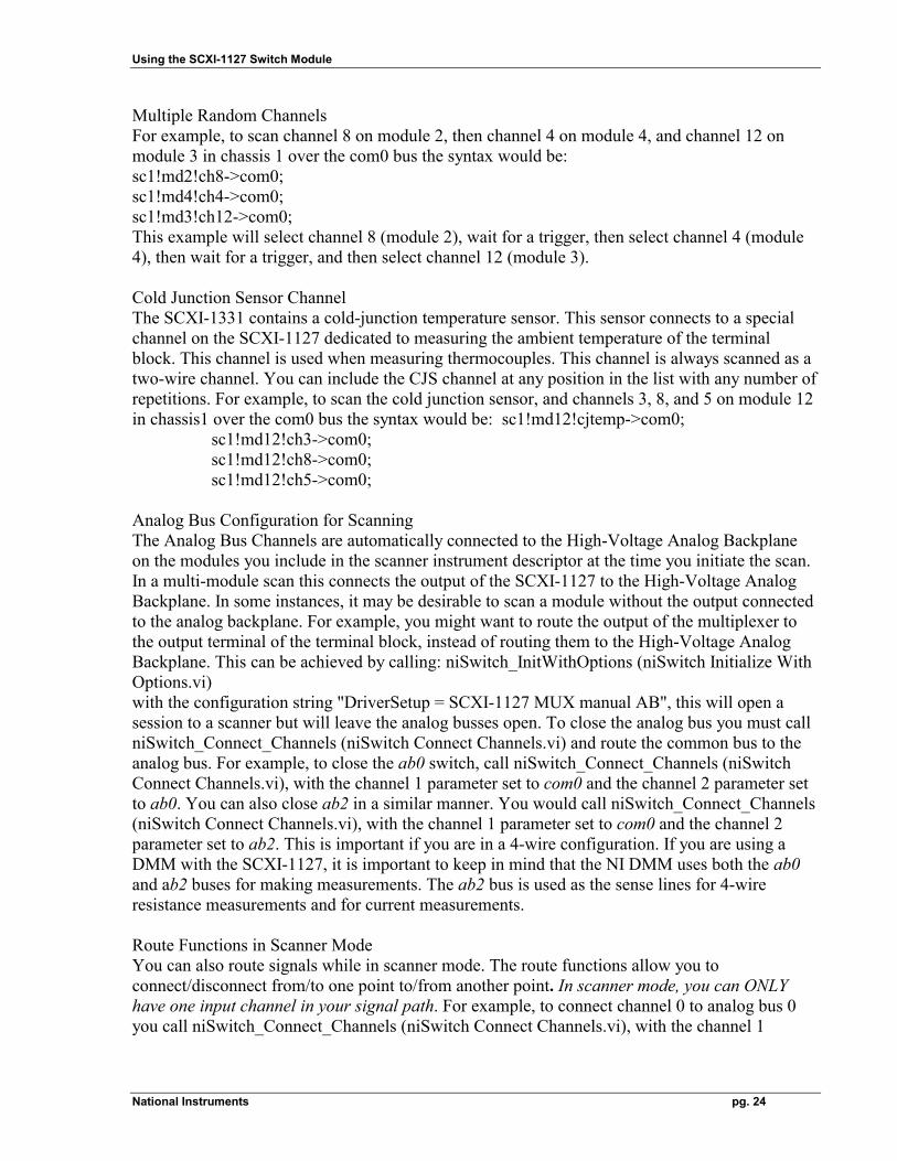
Analog Bus Configuration for Scanning The Analog Bus Channels are automatically connected to the High-Voltage Analog Backplane on the modules you include in the scanner instrument descriptor at the time you initiate the scan. In a multi-module scan this connects the output of the SCXI-1127 to the High-Voltage Analog Backplane. In some instances, it may be desirable to scan a module without the output connected to the analog backplane. For example, you might want to route the output of the multiplexer to the output terminal of the terminal block, instead of routing them to the High-Voltage Analog Backplane. This can be achieved by calling: niSwitch_InitWithOptions (niSwitch Initialize With Options.vi) with the configuration string "DriverSetup = SCXI-1127 MUX manual AB", this will open a session to a scanner but will leave the analog busses open. To close the analog bus you must call niSwitch_Connect_Channels (niSwitch Connect Channels.vi) and route the common bus to the analog bus. For example, to close the ab0 switch, call niSwitch_Connect_Channels (niSwitch Connect Channels.vi), with the channel 1 parameter set to com0 and the channel 2 parameter set to ab0. You can also close ab2 in a similar manner. You would call niSwitch_Connect_Channels (niSwitch Connect Channels.vi), with the channel 1 parameter set to com0 and the channel 2 parameter set to ab2. This is important if you are in a 4-wire configuration. If you are using a DMM with the SCXI-1127, it is important to keep in mind that the NI DMM uses both the ab0 and ab2 buses for making measurements. The ab2 bus is used as the sense lines for 4-wire resistance measurements and for current measurements. Route Functions in Scanner Mode You can also route signals while in scanner mode. The route functions allow you to connect/disconnect from/to one point to/from another point. In scanner mode, you can ONLY have one input channel in your signal path. For example, to connect channel 0 to analog bus 0 you call niSwitch_Connect_Channels (niSwitch Connect Channels.vi), with the channel 1
Using the SCXI-1127 Switch Module
National Instruments pg. 25
parameter set to ch0 and the channel 2 parameter set to com0. Then call niSwitch_Connect_Channels (niSwitch Connect Channels.vi), with the channel 1 parameter set to com0 and the channel 2 parameter to ab0. A list of valid channels for the SCXI-1127 is listed below.
Analog Bus Channel (ab0, ab1, ab2, ab3) These are the four signals which comprise the SCXI High Voltage Analog Bus on the SCXI-1127 Common Bus Channel (com0) This is the internal bus on the scanners. On the SCXI-1127, the input channels can be connected to the common bus. The common bus can also be connected to the analog bus channels. Input Channels (ch0…ch63) These are the 64 one wire input channels on the SCXI-1127. Channels (ch0…ch31) can be configured as two wire inputs. Channels (ch0…ch15) can be configured as four wire inputs. Cold Junction Sensor (cjtemp) The cold junction sensor channel on the SCXI-1331 terminal block can be accessed through the SCXI-1127. To read from this channel call niSwitch_Connect_Channels (niSwitch Connect Channels.vi), with the channel 1 parameter set to cjtemp and the channel 2 parameter to com0. Then call niSwitch_Connect_Channels (niSwitch Connect Channels.vi), with the channel 1 parameter set to com0 and the channel 2 parameter to ab0. The output of the CJS sensor will now be present on analog bus 0. Input Mode Configuration In the scanner mode, the input channels can be configured on a per-channel basis. This configuration is done through the Measurement and Automation Explorer.
LabVIEW example
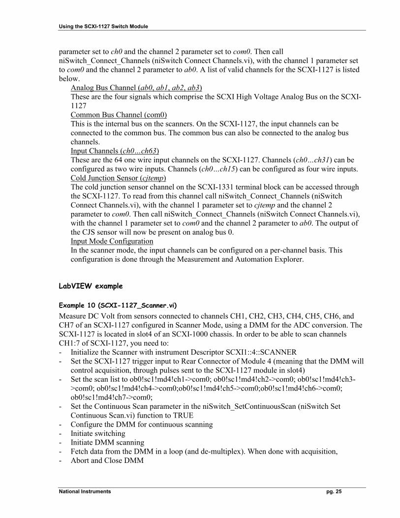
Example 10 (SCXI-1127_Scanner.vi) Measure DC Volt from sensors connected to channels CH1, CH2, CH3, CH4, CH5, CH6, and CH7 of an SCXI-1127 configured in Scanner Mode, using a DMM for the ADC conversion. The SCXI-1127 is located in slot4 of an SCXI-1000 chassis. In order to be able to scan channels CH1:7 of SCXI-1127, you need to: - Initialize the Scanner with instrument Descriptor SCXI1::4::SCANNER - Set the SCXI-1127 trigger input to Rear Connector of Module 4 (meaning that the DMM will
control acquisition, through pulses sent to the SCXI-1127 module in slot4) - Set the scan list to ob0!sc1!md4!ch1->com0; ob0!sc1!md4!ch2->com0; ob0!sc1!md4!ch3-
>com0; ob0!sc1!md4!ch4->com0;ob0!sc1!md4!ch5->com0;ob0!sc1!md4!ch6->com0; ob0!sc1!md4!ch7->com0;
- Set the Continuous Scan parameter in the niSwitch_SetContinuousScan (niSwitch Set Continuous Scan.vi) function to TRUE
- Configure the DMM for continuous scanning - Initiate switching - Initiate DMM scanning - Fetch data from the DMM in a loop (and de-multiplex). When done with acquisition, - Abort and Close DMM
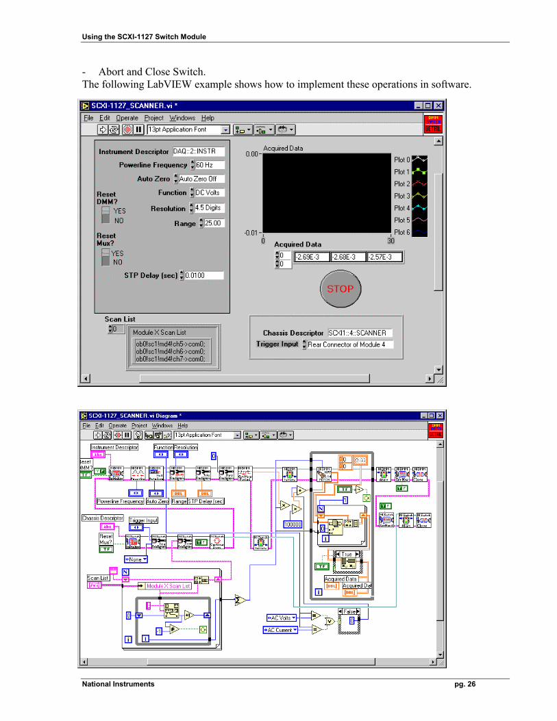
Using the SCXI-1127 Switch Module
National Instruments pg. 26
- Abort and Close Switch. The following LabVIEW example shows how to implement these operations in software.
Using the SCXI-1127 Switch Module
National Instruments pg. 27
LabWindows/CVI example
Example 11 (Scanning SCXI-1127.prj) Measure DC Volt from sensors connected to channels CH0, CH1, and CH2 of an SCXI-1127 configured in Scanner Mode. This example is using a PCI-4060 DMM as controller for the SCXI-1127. which is located in slot4 of an SCXI-1000 chassis. In order to be able to scan channels CH0:2 of SCXI-1127, you need to: • Initialize the Scanner with instrument Descriptor SCXI1::4::SCANNER • Set the SCXI-1127 trigger input to Rear Connector of Module 4 (meaning that the DMM will
control acquisition, through pulses sent to the SCXI-1127 module in slot4) • Set the scan list to "sc1!md4!ch0:2->com0;" • Set the Continuous Scan parameter in the niSwitch_SetContinuousScan (niSwitch Set
Continuous Scan.vi) function to TRUE • Configure the DMM for continuous scanning • Initiate switching • Initiate DMM scanning • Fetch data from the DMM in a loop (and de-multiplex). When done with acquisition, • Abort and Close DMM • Abort and Close Switch. void main(void) { ViStatus error = VI_SUCCESS; ViSession vi = VI_NULL; ViSession instr = VI_NULL; ViString resourceName = "DAQ::2::INSTR"; ViString scxichan = "sc1!md4!ch0:2->com0;"; ViBoolean idQuery = VI_TRUE; ViBoolean reset = VI_TRUE; ViReal64 powerlineFreq = NIDMM_VAL_60_HERTZ; ViInt32 function = NIDMM_VAL_DC_VOLTS; ViReal64 range = 2.00; ViReal64 resolution = NIDMM_VAL_3_5_DIGITS; ViReal64 minFrequency = 20.00; ViReal64 maxFrequency = 25000.00; ViInt32 startTrigSource = NIDMM_VAL_EXTERNAL; ViInt32 startTrigSlope = NIDMM_VAL_POS; ViInt32 numOfMeas = 30; ViReal64 measurements[30]; ViInt32 timeLimit = 30000; ViInt32 numPointsRead; ViReal64 delay = 0.5; ViReal64 period; ViInt32 numpts,i;
Using the SCXI-1127 Switch Module
National Instruments pg. 28
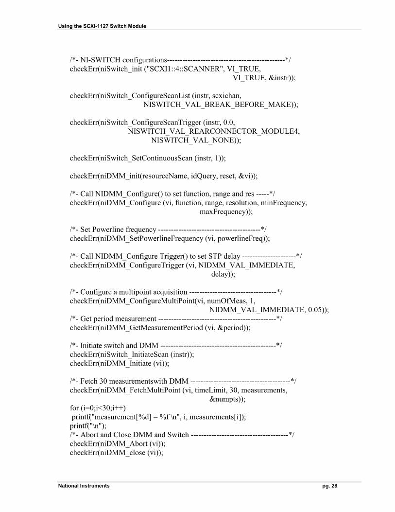
/*- NI-SWITCH configurations----------------------------------------------*/ checkErr(niSwitch_init ("SCXI1::4::SCANNER", VI_TRUE, VI_TRUE, &instr)); checkErr(niSwitch_ConfigureScanList (instr, scxichan, NISWITCH_VAL_BREAK_BEFORE_MAKE)); checkErr(niSwitch_ConfigureScanTrigger (instr, 0.0, NISWITCH_VAL_REARCONNECTOR_MODULE4, NISWITCH_VAL_NONE)); checkErr(niSwitch_SetContinuousScan (instr, 1)); checkErr(niDMM_init(resourceName, idQuery, reset, &vi)); /*- Call NIDMM_Configure() to set function, range and res -----*/ checkErr(niDMM_Configure (vi, function, range, resolution, minFrequency, maxFrequency)); /*- Set Powerline frequency ----------------------------------------*/ checkErr(niDMM_SetPowerlineFrequency (vi, powerlineFreq)); /*- Call NIDMM_Configure Trigger() to set STP delay ---------------------*/ checkErr(niDMM_ConfigureTrigger (vi, NIDMM_VAL_IMMEDIATE, delay)); /*- Configure a multipoint acquisition ----------------------------------*/ checkErr(niDMM_ConfigureMultiPoint(vi, numOfMeas, 1, NIDMM_VAL_IMMEDIATE, 0.05)); /*- Get period measurement ----------------------------------------------*/ checkErr(niDMM_GetMeasurementPeriod (vi, &period)); /*- Initiate switch and DMM ---------------------------------------------*/ checkErr(niSwitch_InitiateScan (instr)); checkErr(niDMM_Initiate (vi)); /*- Fetch 30 measurementswith DMM ---------------------------------------*/ checkErr(niDMM_FetchMultiPoint (vi, timeLimit, 30, measurements, &numpts)); for (i=0;i<30;i++) printf("measurement[%d] = %f \n", i, measurements[i]); printf("\n"); /*- Abort and Close DMM and Switch --------------------------------------*/ checkErr(niDMM_Abort (vi)); checkErr(niDMM_close (vi));
Using the SCXI-1127 Switch Module
National Instruments pg. 29
checkErr(niSwitch_AbortScan (instr)); checkErr(niSwitch_close (instr)); Error: if (vi) niDMM_close(vi); if (error < VI_SUCCESS) messageHandler(error); }
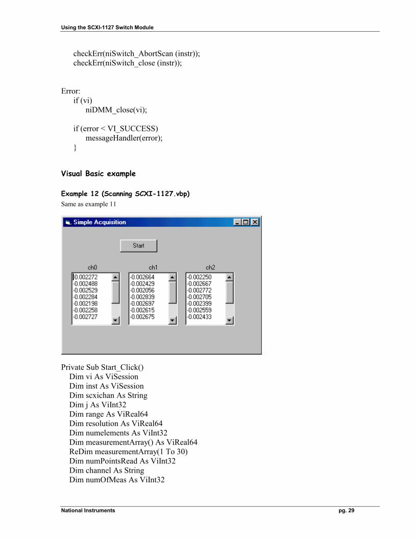
Visual Basic example
Example 12 (Scanning SCXI-1127.vbp) Same as example 11
Private Sub Start_Click() Dim vi As ViSession Dim inst As ViSession Dim scxichan As String Dim j As ViInt32 Dim range As ViReal64 Dim resolution As ViReal64 Dim numelements As ViInt32 Dim measurementArray() As ViReal64 ReDim measurementArray(1 To 30) Dim numPointsRead As ViInt32 Dim channel As String Dim numOfMeas As ViInt32
Using the SCXI-1127 Switch Module
National Instruments pg. 30
Dim minFrequency As ViReal64 Dim maxFrequency As ViReal64 scxichan = "sc1!md4!ch0:2->com0;" measurements1.Text = "" measurements2.Text = "" measurements3.Text = "" range = 10# resolution = 1# numOfMeas = 30 minFrequency = 20# maxFrequency = 25000# 'Disable Acquire button until acquistion complete Start.Enabled = False 'NI-SWITCH configurations If CheckError(niSwitch_init("SCXI1::4::SCANNER", VI_TRUE, VI_TRUE, inst)) Then GoTo Error End If If CheckError(niSwitch_ConfigureScanTrigger(inst, 0#, _ NISWITCH_VAL_REARCONNECTOR_MODULE4, _ NISWITCH_VAL_NONE)) Then GoTo Error End If If CheckError(niSwitch_ConfigureScanList(inst, scxichan, _ NISWITCH_VAL_BREAK_BEFORE_MAKE)) Then GoTo Error End If If CheckError(niSwitch_SetContinuousScan(inst, 1)) Then GoTo Error End If 'Begin by opening a communication channel to the DMM If CheckError(niDMM_init("DAQ::1::INSTR", VI_TRUE, VI_TRUE, vi)) Then GoTo Error End If 'Call NIDMM_ConfigureMeasurement() to set function, range and resolution If CheckError(niDMM_Configure(vi, NIDMM_VAL_DC_VOLTS, _ range, resolution, minFrequency, maxFrequency)) Then GoTo Error End If
Using the SCXI-1127 Switch Module
National Instruments pg. 31
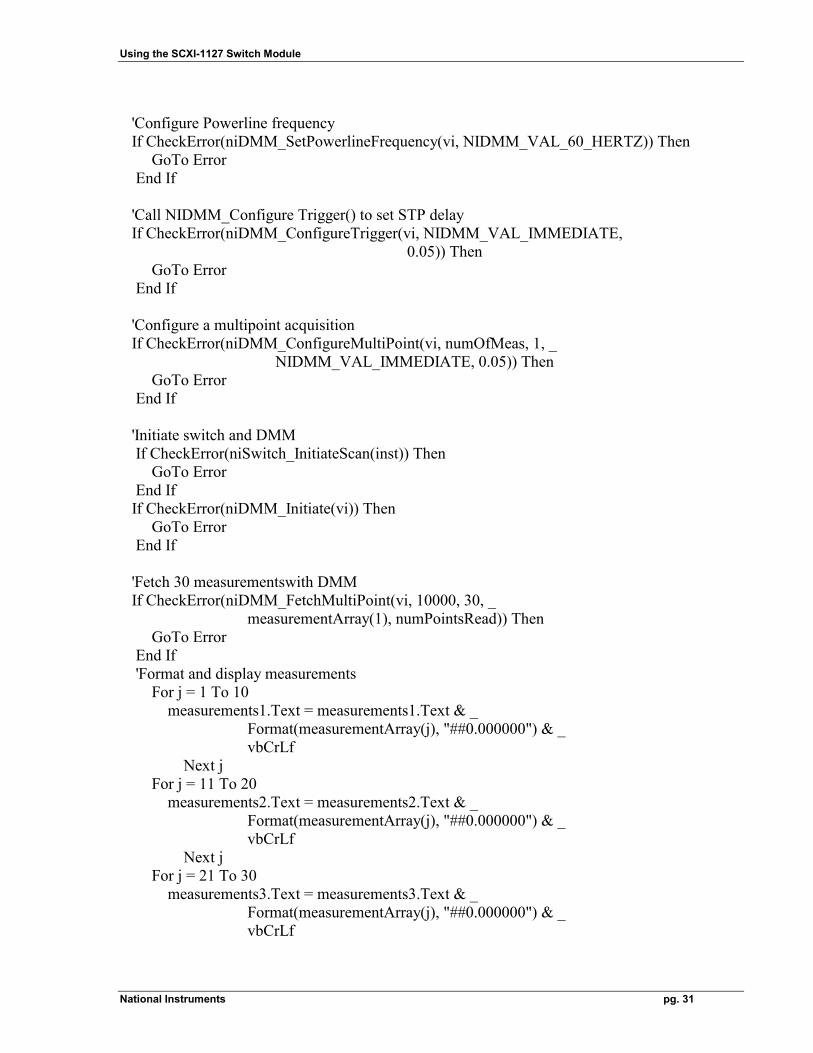
'Configure Powerline frequency If CheckError(niDMM_SetPowerlineFrequency(vi, NIDMM_VAL_60_HERTZ)) Then GoTo Error End If 'Call NIDMM_Configure Trigger() to set STP delay If CheckError(niDMM_ConfigureTrigger(vi, NIDMM_VAL_IMMEDIATE, 0.05)) Then GoTo Error End If 'Configure a multipoint acquisition If CheckError(niDMM_ConfigureMultiPoint(vi, numOfMeas, 1, _ NIDMM_VAL_IMMEDIATE, 0.05)) Then GoTo Error End If 'Initiate switch and DMM If CheckError(niSwitch_InitiateScan(inst)) Then GoTo Error End If If CheckError(niDMM_Initiate(vi)) Then GoTo Error End If 'Fetch 30 measurementswith DMM If CheckError(niDMM_FetchMultiPoint(vi, 10000, 30, _ measurementArray(1), numPointsRead)) Then GoTo Error End If 'Format and display measurements For j = 1 To 10 measurements1.Text = measurements1.Text & _ Format(measurementArray(j), "##0.000000") & _ vbCrLf Next j For j = 11 To 20 measurements2.Text = measurements2.Text & _ Format(measurementArray(j), "##0.000000") & _ vbCrLf Next j For j = 21 To 30 measurements3.Text = measurements3.Text & _ Format(measurementArray(j), "##0.000000") & _ vbCrLf

Using the SCXI-1127 Switch Module
National Instruments pg. 32
Next j 'Abort and Close DMM and Switch If CheckError(niDMM_Abort(vi)) Then GoTo Error End If If CheckError(niDMM_close(vi)) Then GoTo Error End If If CheckError(niSwitch_close(inst)) Then GoTo Error End If Error: 'Enable acquire button Start.Enabled = True End Sub
Using the SCXI-1127 Switch Module
National Instruments pg. 33
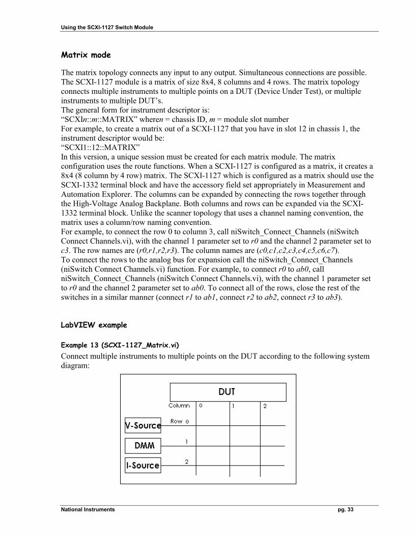
Matrix mode The matrix topology connects any input to any output. Simultaneous connections are possible. The SCXI-1127 module is a matrix of size 8x4, 8 columns and 4 rows. The matrix topology connects multiple instruments to multiple points on a DUT (Device Under Test), or multiple instruments to multiple DUT’s. The general form for instrument descriptor is: “SCXIn::m::MATRIX” wheren = chassis ID, m = module slot number For example, to create a matrix out of a SCXI-1127 that you have in slot 12 in chassis 1, the instrument descriptor would be: “SCXI1::12::MATRIX” In this version, a unique session must be created for each matrix module. The matrix configuration uses the route functions. When a SCXI-1127 is configured as a matrix, it creates a 8x4 (8 column by 4 row) matrix. The SCXI-1127 which is configured as a matrix should use the SCXI-1332 terminal block and have the accessory field set appropriately in Measurement and Automation Explorer. The columns can be expanded by connecting the rows together through the High-Voltage Analog Backplane. Both columns and rows can be expanded via the SCXI-1332 terminal block. Unlike the scanner topology that uses a channel naming convention, the matrix uses a column/row naming convention. For example, to connect the row 0 to column 3, call niSwitch_Connect_Channels (niSwitch Connect Channels.vi), with the channel 1 parameter set to r0 and the channel 2 parameter set to c3. The row names are (r0,r1,r2,r3). The column names are (c0,c1,c2,c3,c4,c5,c6,c7). To connect the rows to the analog bus for expansion call the niSwitch_Connect_Channels (niSwitch Connect Channels.vi) function. For example, to connect r0 to ab0, call niSwitch_Connect_Channels (niSwitch Connect Channels.vi), with the channel 1 parameter set to r0 and the channel 2 parameter set to ab0. To connect all of the rows, close the rest of the switches in a similar manner (connect r1 to ab1, connect r2 to ab2, connect r3 to ab3).
LabVIEW example
Example 13 (SCXI-1127_Matrix.vi) Connect multiple instruments to multiple points on the DUT according to the following system diagram:
Using the SCXI-1127 Switch Module
National Instruments pg. 34
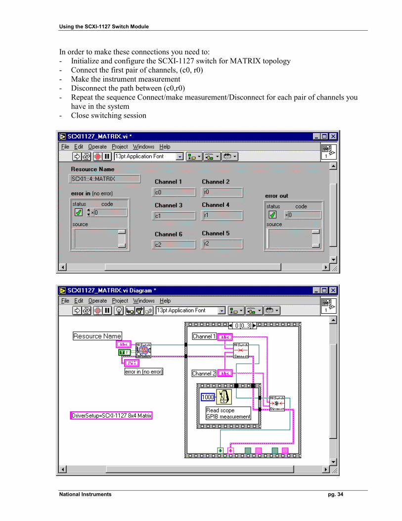
In order to make these connections you need to: - Initialize and configure the SCXI-1127 switch for MATRIX topology - Connect the first pair of channels, (c0, r0) - Make the instrument measurement - Disconnect the path between (c0,r0) - Repeat the sequence Connect/make measurement/Disconnect for each pair of channels you
have in the system - Close switching session
Using the SCXI-1127 Switch Module
National Instruments pg. 35
LabWindows/CVI example
Example 14 (SCXI-1127_Matrix.prj) Connect multiple instruments to multiple points on the DUT according to the following system diagram: c0/r0, c1/r2, c5/r3. In order to make these connections you need to: • Initialize and configure the SCXI-1127 switch for MATRIX topology • Connect the first pair of channels, (c0, r0) • Make the instrument measurement • Disconnect the path between (c0,r0) • Repeat the sequence Connect/make measurement/Disconnect for each pair of channels you
have in the system • Close switching session int main (void) { ViSession instr; /* Communication Channel */ ViStatus status; /* For checking errors */ /* Begin by opening a communication channel to the instrument */ status = niSwitch_init("SCXI1::4::MATRIX", VI_TRUE, VI_TRUE, &instr); if (status < VI_SUCCESS) /* Error Initializing Interface...exiting */ return -1; /* Close switch c0/r0 */ status = niSwitch_Connect(instr, "c0", "r0"); if (status < VI_SUCCESS) /* Error Initializing Interface...exiting */ return -1; Delay (2); /* Close switch c1/r2 */ status = niSwitch_Connect(instr, "c1", "r2"); if (status < VI_SUCCESS) /* Error Initializing Interface...exiting */ return -1; Delay (2); /* Close switch c5/r3 */ status = niSwitch_Connect(instr, "c5", "r3"); if (status < VI_SUCCESS) /* Error Initializing Interface...exiting */ return -1;
Using the SCXI-1127 Switch Module
National Instruments pg. 36
Delay (2); /* Close communication channel */ status = niSwitch_close(instr); return 0; }
Visual Basic example
Example 15 (SCXI-1127_Matrix.vbp) Same as example 14
Private Sub Start_Click() Dim vi As ViSession Dim i As ViInt32 'Disable Acquire button until acquistion complete Start.Enabled = False ' Begin by opening a communication channel to the instrument If CheckError(niSwitch_init("SCXI1::4::MATRIX", VI_TRUE, VI_TRUE, vi)) Then GoTo Error End If ' Close switch c0/r0 If CheckError(niSwitch_Connect(vi, "c0", "r0")) Then GoTo Error End If ' Close switch c1/r2 If CheckError(niSwitch_Connect(vi, "c1", "r2")) Then GoTo Error End If ' Close switch c5/r3 If CheckError(niSwitch_Connect(vi, "c5", "r3")) Then

Using the SCXI-1127 Switch Module
National Instruments pg. 37
GoTo Error End If ' Close communication channel If CheckError(niSwitch_close(vi)) Then GoTo Error End If Error: 'Enable acquire button Start.Enabled = True End Sub
Using the SCXI-1127 Switch Module
National Instruments pg. 38
Measurement and switching systems The programmable thermometer - Multiplex 32 thermocouple inputs - Expand to 384 inputs - Thermocouple types B,E,J,K,R,S,T,N - Deg Celsius, Fahrenheit, Kelvin, or mV readings - Display and store temperature profiles - Record temperature trends
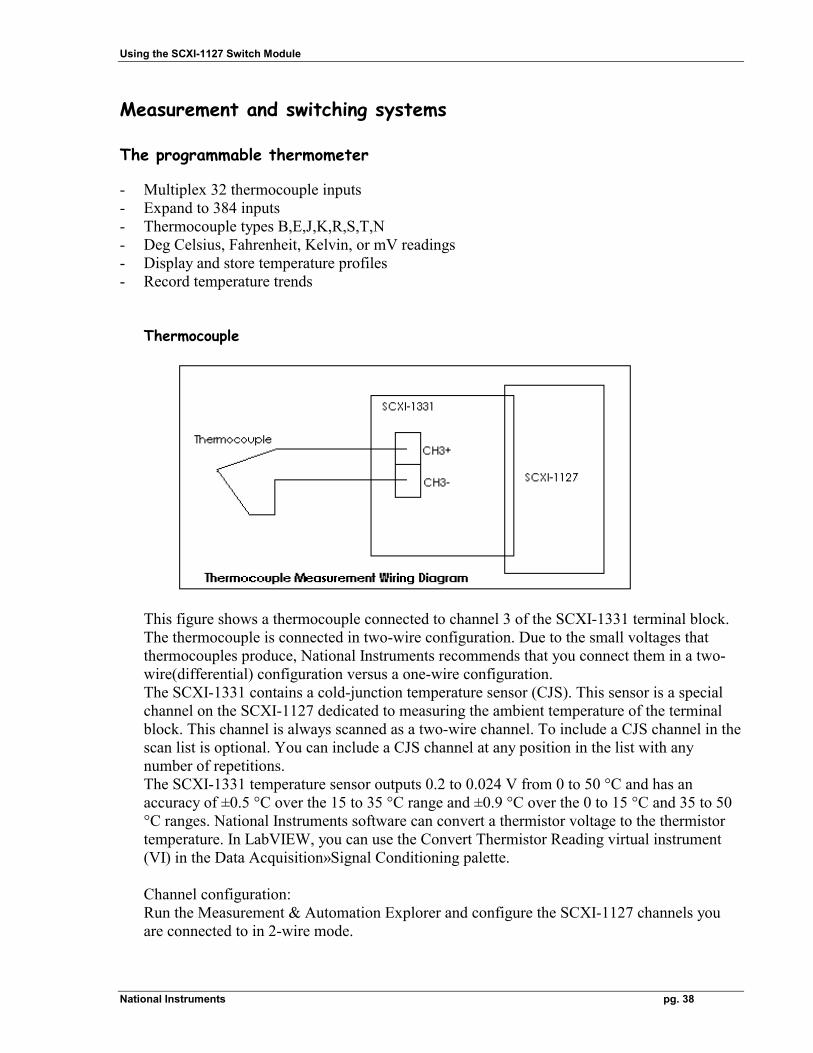
Thermocouple
This figure shows a thermocouple connected to channel 3 of the SCXI-1331 terminal block. The thermocouple is connected in two-wire configuration. Due to the small voltages that thermocouples produce, National Instruments recommends that you connect them in a two-wire(differential) configuration versus a one-wire configuration. The SCXI-1331 contains a cold-junction temperature sensor (CJS). This sensor is a special channel on the SCXI-1127 dedicated to measuring the ambient temperature of the terminal block. This channel is always scanned as a two-wire channel. To include a CJS channel in the scan list is optional. You can include a CJS channel at any position in the list with any number of repetitions. The SCXI-1331 temperature sensor outputs 0.2 to 0.024 V from 0 to 50 °C and has an accuracy of ±0.5 °C over the 15 to 35 °C range and ±0.9 °C over the 0 to 15 °C and 35 to 50 °C ranges. National Instruments software can convert a thermistor voltage to the thermistor temperature. In LabVIEW, you can use the Convert Thermistor Reading virtual instrument (VI) in the Data Acquisition»Signal Conditioning palette.
Channel configuration: Run the Measurement & Automation Explorer and configure the SCXI-1127 channels you are connected to in 2-wire mode.
Using the SCXI-1127 Switch Module
National Instruments pg. 39
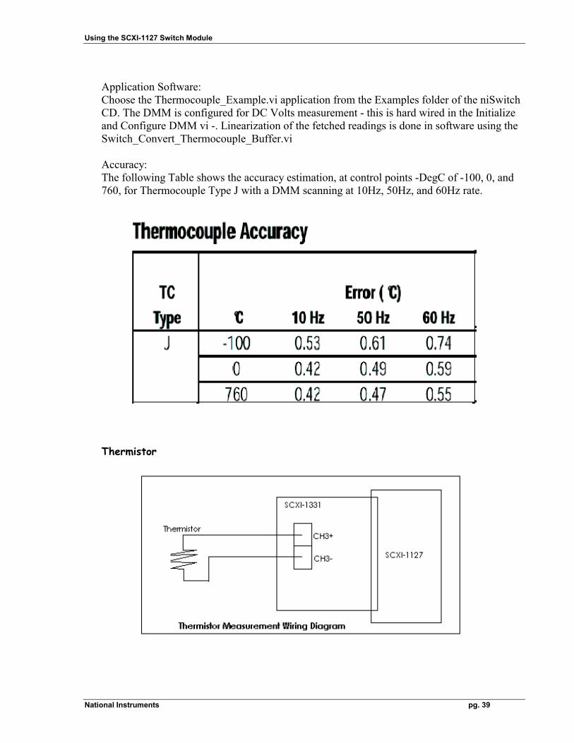
Application Software: Choose the Thermocouple_Example.vi application from the Examples folder of the niSwitch CD. The DMM is configured for DC Volts measurement - this is hard wired in the Initialize and Configure DMM vi -. Linearization of the fetched readings is done in software using the Switch_Convert_Thermocouple_Buffer.vi Accuracy: The following Table shows the accuracy estimation, at control points -DegC of -100, 0, and 760, for Thermocouple Type J with a DMM scanning at 10Hz, 50Hz, and 60Hz rate.
Thermistor
Using the SCXI-1127 Switch Module
National Instruments pg. 40
Channel configuration: Run the Measurement & Automation Explorer and configure the SCXI-1127 channels you are connected to in 2-wire mode. Application Software: Choose the Thermistor_Example.vi application from the Examples folder of the niSwitch CD. The DMM is configured for 2-Wire Resistance measurement - this is hard wired in the Initialize and Configure DMM vi -. Linearization of the fetched readings is done in software using the Convert_Thermistor_Reading.vi
Accuracy: Measurement of 55 Ohms under the following conditions: - in 200Ohms range, - at a temperature of 28degC, - 24 hours after calibration is done with an error of 0.0533Ohms.
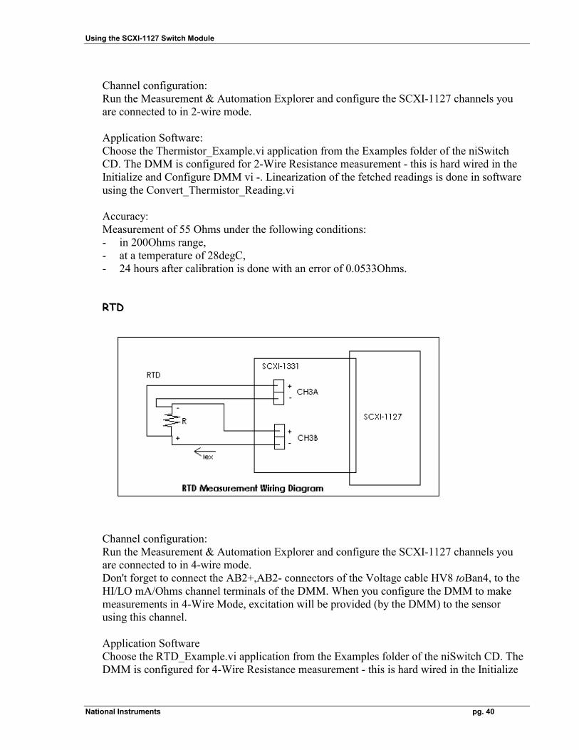
RTD
Channel configuration: Run the Measurement & Automation Explorer and configure the SCXI-1127 channels you are connected to in 4-wire mode. Don't forget to connect the AB2+,AB2- connectors of the Voltage cable HV8 toBan4, to the HI/LO mA/Ohms channel terminals of the DMM. When you configure the DMM to make measurements in 4-Wire Mode, excitation will be provided (by the DMM) to the sensor using this channel. Application Software Choose the RTD_Example.vi application from the Examples folder of the niSwitch CD. The DMM is configured for 4-Wire Resistance measurement - this is hard wired in the Initialize
Using the SCXI-1127 Switch Module
National Instruments pg. 41
and Configure DMM vi -. Linearization of the fetched readings is done in software using the Convert_RTD_Reading.vi Note: when using the SCXI-1127 and the NI 4060 hardware, you can a) combine different types of sensors inside the SCXI-1131 terminal block, b) configure your channels in different modes (1-wire, 2-wire, 4-wire) c) scan several channels, all requesting the same DMM function. In a scanning operation you can NOT scan channels requesting different DMM functions. For example, you can not have the followings: - a channel string of: ob0!sc1!md4!ch26->com0; ob0!sc1!md4!ch27->com0;
ob0!sc1!md4!ch28->com0; and - have ch26 scanned as DC Volt reading by the DMM - have ch27 scanned as 2-Wire Resistance reading by the DMM - have ch27 scanned as 4-Wire Resistance reading by the DMM all in the same scan list. The NI 4060 can not change its measurement function on the fly, during a scan operation.
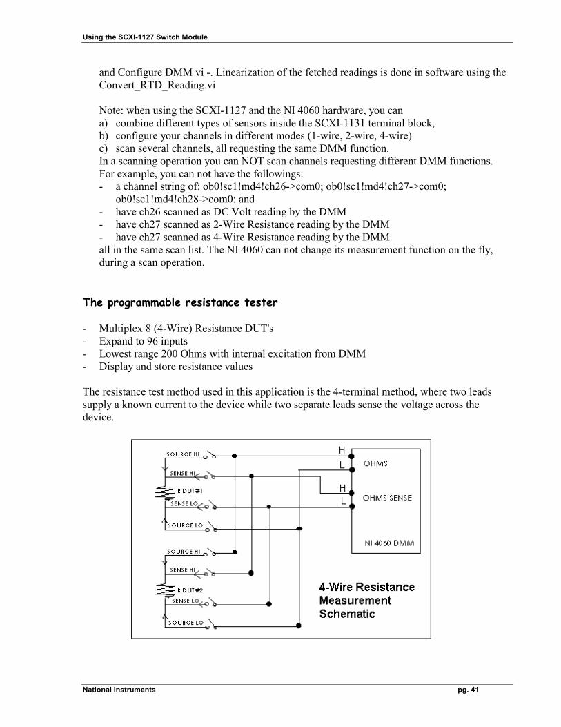
The programmable resistance tester - Multiplex 8 (4-Wire) Resistance DUT's - Expand to 96 inputs - Lowest range 200 Ohms with internal excitation from DMM - Display and store resistance values The resistance test method used in this application is the 4-terminal method, where two leads supply a known current to the device while two separate leads sense the voltage across the device.
Using the SCXI-1127 Switch Module
National Instruments pg. 42
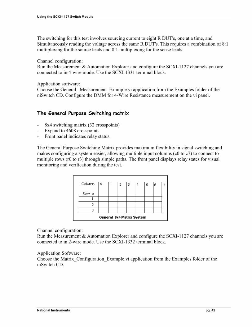
The switching for this test involves sourcing current to eight R DUT's, one at a time, and Simultaneously reading the voltage across the same R DUT's. This requires a combination of 8:1 multiplexing for the source leads and 8:1 multiplexing for the sense leads. Channel configuration: Run the Measurement & Automation Explorer and configure the SCXI-1127 channels you are connected to in 4-wire mode. Use the SCXI-1331 terminal block. Application software: Choose the General _Measurement_Example.vi application from the Examples folder of the niSwitch CD. Configure the DMM for 4-Wire Resistance measurement on the vi panel. The General Purpose Switching matrix - 8x4 switching matrix (32 crosspoints) - Expand to 4608 crosspoints - Front panel indicates relay status The General Purpose Switching Matrix provides maximum flexibility in signal switching and makes configuring a system easier, allowing multiple input columns (c0 to c7) to connect to multiple rows (r0 to r3) through simple paths. The front panel displays relay states for visual monitoring and verification during the test.
Channel configuration: Run the Measurement & Automation Explorer and configure the SCXI-1127 channels you are connected to in 2-wire mode. Use the SCXI-1332 terminal block. Application Software: Choose the Matrix_Configuration_Example.vi application from the Examples folder of the niSwitch CD.

Using the SCXI-1127 Switch Module
National Instruments pg. 43