Embed Size (px)
Citation preview

Introduction I recently bought a unit on EBay that looked very interesting, from an Israel-based seller “Art-in-Part”. The Thales 23GHz transceiver unit appeared to be a complete TX/RX unit with the potential of just needing a local oscillator to make up a 24GHz Transverter. Fig 1 shows the 26GHz version. This article refers to the 23GHz version which is marked TGTR23. It has TX and RX WG20 ports, and SMA connectors marked TX IF, RX IF and LO. Thought they appear to be mechanically identical, I have not tried to modify a 26GHz version. Connections I don't have the control pinout (7 pin con-nector) but they can all be left unconnected. Applying +8 Volts to the unit makes it trans-mit. The unit takes over an Amp on receive and nearly 2 Amps on Transmit The power pinout is as follows: 1: +5V 2: GND 3: -12V 4: +8V Transmit Pin 1 is the one further away from the centre (or closest to the side of the unit Inside the box Carefully opening up the box you can see what is inside (Fig 2) At the top left is a Receiver LNA, to the right and below is a mixer and at the top right is a PA. Looking at the LO filter in the centre it ap-pears that the LO is at
Scatterpoint Scatterpoint Scatterpoint Scatterpoint Page 1Page 1Page 1Page 1
Using the Thales TGTRUsing the Thales TGTRUsing the Thales TGTRUsing the Thales TGTR----23 23 23 23
23GHz 23GHz 23GHz 23GHz Transceiver unit on 24GHz John Worsnop G4BAOJohn Worsnop G4BAOJohn Worsnop G4BAOJohn Worsnop G4BAO
Fig 1 Thales 26GHz Transceiver (picture Art-in-Part)
Fig 2 Inside the box (picture F4EXB)
1/2 the final frequency (+/- IF). The filter at the top is at the final frequency as the fingers are about half the size of the LO filter. Use on 24GHz I first applied a low side LO at (24048 –432)/2, i.e 11808MHz, and a 432MHz IF signal. Around –20 dBm at IF and +15dBm at LO produced a saturated output of around 1.2 Watts. I then looked at the output on a spectrum analyser. The LO leakage at 2x11808MHz falls at 23616MHz right in the centre of the passband of the transmitter resulting in an LO level the same as the wanted 24GHz signal! Almost 1 Watt of LO leakage. Clearly not very good! I then switched to high side injection at (24048 +432)/2 i.e. 12240 and this was much better. Now the LO leakage was -16 dB down on the carrier, the image at 24912 –23dB down. Adding a waveguide bandpass filter at 24048 in the transmit leg reduces the unwanted signals to below –60dB leaving a clean 1.2Watts of RF at 24GHz. On receive, with no extra filtering I measured a conversion gain of 30 dB and a noise figure of 3.3dB. Very acceptable! Putting it all together Adding a DB6NT 12GHz multiplier driven from an external G4HUP DDS, +8, +5 and –12 Volt power supplies, a PIC to do some control, sequencing and switching for a Relcom WG22 relay and adap-tors, with a coaxial relay on the input you now have a complete 24GHz transverter system that gives a conversion gain of 29dB, and around 4dB noise figure.
Fig 3 System block diagram
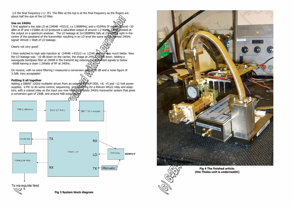
Fig 4 The finished article. (the Thales unit is underneath!)