Embed Size (px)
Citation preview
ibm.com/redbooks
Using ThinkVantage Technologies:Volume 1 Creating andDeploying Client Systems
Lucas BiggersJames Cowles
Håkon FosshaugJohan FreidlitzKeith Gedrose
Chris HollandDavid KohlerJamel Lynch
Yossi SoberanoByron Braswell
Simplification of the PC life cycle process with ThinkVantage Technologies
Simple deployment of complex corporate environments
Use of the technologies to lower costs
Front cover

Using ThinkVantage Technologies: Volume 1 Creating and Deploying Client Systems
November 2005
International Technical Support Organization
SG24-7106-00
© Copyright International Business Machines Corporation 2005. All rights reserved.Note to U.S. Government Users Restricted Rights -- Use, duplication or disclosure restricted by GSA ADPSchedule Contract with IBM Corp.
First Edition (November 2005)
This edition applies to Version 3 of ImageUltra Builder, Version 5 of System Migration Assistant, Version 3.81 of Access Connections, Version 1.3 of Secure Data Disposal, and Version 1.33b of Active Protection System
Note: Before using this information and the product it supports, read the information in “Notices” on page ix.
Contents
Notices . . . . . . . . . . . . . . . . . . . . . . . . . . . . . . . . . . . . . . . . . . . . . . . . . . . . . . . ixTrademarks . . . . . . . . . . . . . . . . . . . . . . . . . . . . . . . . . . . . . . . . . . . . . . . . . . . . x
Preface . . . . . . . . . . . . . . . . . . . . . . . . . . . . . . . . . . . . . . . . . . . . . . . . . . . . . . . xiThe team that wrote this redbook. . . . . . . . . . . . . . . . . . . . . . . . . . . . . . . . . . . . xiBecome a published author . . . . . . . . . . . . . . . . . . . . . . . . . . . . . . . . . . . . . . . xviComments welcome. . . . . . . . . . . . . . . . . . . . . . . . . . . . . . . . . . . . . . . . . . . . xvii
Summary of changes . . . . . . . . . . . . . . . . . . . . . . . . . . . . . . . . . . . . . . . . . . . xixOctober 2005, First Edition. . . . . . . . . . . . . . . . . . . . . . . . . . . . . . . . . . . . . . . . xix
Chapter 1. Introduction . . . . . . . . . . . . . . . . . . . . . . . . . . . . . . . . . . . . . . . . . . 11.1 ThinkVantage Technologies . . . . . . . . . . . . . . . . . . . . . . . . . . . . . . . . . . . . 31.2 ThinkVantage Technologies process improvements. . . . . . . . . . . . . . . . . . 81.3 Implementing a ThinkVantage Technologies solution. . . . . . . . . . . . . . . . . 9
Chapter 2. ImageUltra Builder . . . . . . . . . . . . . . . . . . . . . . . . . . . . . . . . . . . 132.1 Introduction . . . . . . . . . . . . . . . . . . . . . . . . . . . . . . . . . . . . . . . . . . . . . . . . 15
2.1.1 What’s new with ImageUltra Builder 3.0? . . . . . . . . . . . . . . . . . . . . . 152.2 Image management . . . . . . . . . . . . . . . . . . . . . . . . . . . . . . . . . . . . . . . . . 17
2.2.1 Traditional tools and processes for building systems . . . . . . . . . . . . 172.2.2 Image complexity leads to image management problems . . . . . . . . 18
2.3 ImageUltra Builder components and basic operation . . . . . . . . . . . . . . . . 192.3.1 ImageUltra Builder terminology. . . . . . . . . . . . . . . . . . . . . . . . . . . . . 21
2.4 ImageUltra Builder installation and setup . . . . . . . . . . . . . . . . . . . . . . . . . 262.4.1 Installation . . . . . . . . . . . . . . . . . . . . . . . . . . . . . . . . . . . . . . . . . . . . . 272.4.2 Repository and user administration. . . . . . . . . . . . . . . . . . . . . . . . . . 29
2.5 Module options and usage . . . . . . . . . . . . . . . . . . . . . . . . . . . . . . . . . . . . 392.5.1 General tab . . . . . . . . . . . . . . . . . . . . . . . . . . . . . . . . . . . . . . . . . . . . 402.5.2 OS/Languages tab . . . . . . . . . . . . . . . . . . . . . . . . . . . . . . . . . . . . . . 402.5.3 Source tab. . . . . . . . . . . . . . . . . . . . . . . . . . . . . . . . . . . . . . . . . . . . . 412.5.4 Filters tab . . . . . . . . . . . . . . . . . . . . . . . . . . . . . . . . . . . . . . . . . . . . . 412.5.5 Options tab . . . . . . . . . . . . . . . . . . . . . . . . . . . . . . . . . . . . . . . . . . . . 412.5.6 Modules provided with the builder. . . . . . . . . . . . . . . . . . . . . . . . . . . 432.5.7 Creating custom modules . . . . . . . . . . . . . . . . . . . . . . . . . . . . . . . . . 472.5.8 Creating an application module from source files . . . . . . . . . . . . . . . 502.5.9 Creating a device driver module from source files . . . . . . . . . . . . . . 562.5.10 Import preload modules into the repository. . . . . . . . . . . . . . . . . . . 66
2.6 Smart Image types . . . . . . . . . . . . . . . . . . . . . . . . . . . . . . . . . . . . . . . . . . 67
© Copyright IBM Corp. 2005. All rights reserved. iii
2.6.1 Smart Image types defined . . . . . . . . . . . . . . . . . . . . . . . . . . . . . . . . 672.6.2 Smart Image types compared . . . . . . . . . . . . . . . . . . . . . . . . . . . . . . 71
2.7 Preparing the repository for Smart Image creation . . . . . . . . . . . . . . . . . . 732.8 Hardware-Specific Image . . . . . . . . . . . . . . . . . . . . . . . . . . . . . . . . . . . . . 78
2.8.1 Creating a seed system for use in Hardware-Specific Image . . . . . . 782.8.2 Using a Traditional Image in a Hardware-Specific Image solution . . 80
2.9 Portable-Sysprep Image . . . . . . . . . . . . . . . . . . . . . . . . . . . . . . . . . . . . . . 992.9.1 Preparing the seed system for the Portable-Sysprep Image . . . . . 1002.9.2 Using a Traditional Image in a Portable-Sysprep Image solution . . 1022.9.3 Portable-Sysprep Image from Lenovo preload modules. . . . . . . . . 121
2.10 Ultra-Portable Image . . . . . . . . . . . . . . . . . . . . . . . . . . . . . . . . . . . . . . . 1232.10.1 Begin build creation process . . . . . . . . . . . . . . . . . . . . . . . . . . . . . 1252.10.2 Ultra-Portable Image from a Lenovo preloaded system . . . . . . . . 142
2.11 Deploy and install with ImageUltra Builder . . . . . . . . . . . . . . . . . . . . . . 1442.11.1 Deployment process overview . . . . . . . . . . . . . . . . . . . . . . . . . . . 1442.11.2 The deployment environment (Windows PE) . . . . . . . . . . . . . . . . 1462.11.3 CD-ROM/DVD deployment . . . . . . . . . . . . . . . . . . . . . . . . . . . . . . 1462.11.4 Network deployment . . . . . . . . . . . . . . . . . . . . . . . . . . . . . . . . . . . 1522.11.5 Install phase . . . . . . . . . . . . . . . . . . . . . . . . . . . . . . . . . . . . . . . . . 1622.11.6 Deploying ImageUltra Builder images using a USB device . . . . . 1632.11.7 Deployment and installation troubleshooting . . . . . . . . . . . . . . . . 1662.11.8 Creating an ISO image of the network boot CD . . . . . . . . . . . . . . 1692.11.9 Windows PE and boot CD customization . . . . . . . . . . . . . . . . . . . 170
2.12 ThinkVantage integration considerations . . . . . . . . . . . . . . . . . . . . . . . 1732.12.1 Integration with IBM Software Delivery Center (SDC) . . . . . . . . . 1732.12.2 Integration with System Migration Assistant (SMA) . . . . . . . . . . . 1742.12.3 Integration with Rescue and Recovery . . . . . . . . . . . . . . . . . . . . . 1752.12.4 Integration with LANDesk . . . . . . . . . . . . . . . . . . . . . . . . . . . . . . . 175
Chapter 3. System Migration Assistant. . . . . . . . . . . . . . . . . . . . . . . . . . . 1793.1 System migration and its effects on the organization . . . . . . . . . . . . . . . 181
3.1.1 When is system migration required?. . . . . . . . . . . . . . . . . . . . . . . . 1813.2 Installation considerations . . . . . . . . . . . . . . . . . . . . . . . . . . . . . . . . . . . . 182
3.2.1 Supported operating systems and system requirements . . . . . . . . 1823.2.2 System Migration Assistant components . . . . . . . . . . . . . . . . . . . . 1833.2.3 Basic operations . . . . . . . . . . . . . . . . . . . . . . . . . . . . . . . . . . . . . . . 184
3.3 System Migration Assistant installation . . . . . . . . . . . . . . . . . . . . . . . . . . 1853.3.1 Extracting the System Migration Assistant executable . . . . . . . . . . 1863.3.2 Performing a standard System Migration Assistant installation . . . 1873.3.3 Performing a silent System Migration Assistant installation . . . . . . 1903.3.4 Uninstalling System Migration Assistant . . . . . . . . . . . . . . . . . . . . . 191
3.4 Migration scenarios and types. . . . . . . . . . . . . . . . . . . . . . . . . . . . . . . . . 1913.5 Using System Migration Assistant. . . . . . . . . . . . . . . . . . . . . . . . . . . . . . 193
iv Using ThinkVantage Technologies: Volume 1 Creating and Deploying Client Systems
3.5.1 Capturing settings and files. . . . . . . . . . . . . . . . . . . . . . . . . . . . . . . 1933.6 Customizing the standard migration . . . . . . . . . . . . . . . . . . . . . . . . . . . . 220
3.6.1 Customizing the graphical user interface . . . . . . . . . . . . . . . . . . . . 2213.7 Creating a command file template. . . . . . . . . . . . . . . . . . . . . . . . . . . . . . 2263.8 Customizing the command file . . . . . . . . . . . . . . . . . . . . . . . . . . . . . . . . 228
3.8.1 Command file parameters. . . . . . . . . . . . . . . . . . . . . . . . . . . . . . . . 2283.8.2 File migration commands . . . . . . . . . . . . . . . . . . . . . . . . . . . . . . . . 2343.8.3 Examples of file migration commands . . . . . . . . . . . . . . . . . . . . . . 2383.8.4 Command file behavior during the apply phase . . . . . . . . . . . . . . . 239
3.9 Performing a SMA administrative installation . . . . . . . . . . . . . . . . . . . . . 2403.9.1 Extracting SMAsetup.exe . . . . . . . . . . . . . . . . . . . . . . . . . . . . . . . . 2403.9.2 Preparing the SMA files for rollout . . . . . . . . . . . . . . . . . . . . . . . . . 243
3.10 Using SMA in batch mode. . . . . . . . . . . . . . . . . . . . . . . . . . . . . . . . . . . 2453.10.1 System Migration Assistant capture phase in batch mode . . . . . . 2473.10.2 System Migration Assistant apply phase in batch mode. . . . . . . . 247
3.11 System Migration Assistant migration scenario. . . . . . . . . . . . . . . . . . . 2483.11.1 Creating a batch file for the capture phase . . . . . . . . . . . . . . . . . . 2483.11.2 Creating a command file for migration . . . . . . . . . . . . . . . . . . . . . 254
3.12 ThinkVantage integration considerations . . . . . . . . . . . . . . . . . . . . . . . 2573.12.1 Integration with ImageUltra Builder . . . . . . . . . . . . . . . . . . . . . . . . 2573.12.2 Integration with LANDesk . . . . . . . . . . . . . . . . . . . . . . . . . . . . . . . 257
Chapter 4. Secure Data Disposal . . . . . . . . . . . . . . . . . . . . . . . . . . . . . . . . 2634.1 Secure Data Disposal: Overview. . . . . . . . . . . . . . . . . . . . . . . . . . . . . . . 264
4.1.1 System Requirements. . . . . . . . . . . . . . . . . . . . . . . . . . . . . . . . . . . 2644.1.2 Considerations . . . . . . . . . . . . . . . . . . . . . . . . . . . . . . . . . . . . . . . . 264
4.2 Secure Data Disposal installation . . . . . . . . . . . . . . . . . . . . . . . . . . . . . . 2654.2.1 Creating a Secure Data Disposal boot diskette . . . . . . . . . . . . . . . 265
4.3 Using SCRUB3.EXE . . . . . . . . . . . . . . . . . . . . . . . . . . . . . . . . . . . . . . . . 2674.3.1 Performance considerations . . . . . . . . . . . . . . . . . . . . . . . . . . . . . . 2704.3.2 Practical application . . . . . . . . . . . . . . . . . . . . . . . . . . . . . . . . . . . . 271
4.4 LANDesk Management Suite 8.6 for ThinkVantage Technologies . . . . . 272
Chapter 5. ThinkVantage Access Connections . . . . . . . . . . . . . . . . . . . . 2755.1 Access Connections overview. . . . . . . . . . . . . . . . . . . . . . . . . . . . . . . . . 2765.2 Prerequisites . . . . . . . . . . . . . . . . . . . . . . . . . . . . . . . . . . . . . . . . . . . . . . 277
5.2.1 Hardware and security cross-reference . . . . . . . . . . . . . . . . . . . . . 2785.3 Installation . . . . . . . . . . . . . . . . . . . . . . . . . . . . . . . . . . . . . . . . . . . . . . . . 279
5.3.1 Extraction of source files . . . . . . . . . . . . . . . . . . . . . . . . . . . . . . . . . 2795.3.2 Automated installation. . . . . . . . . . . . . . . . . . . . . . . . . . . . . . . . . . . 2805.3.3 Manual installation . . . . . . . . . . . . . . . . . . . . . . . . . . . . . . . . . . . . . 2805.3.4 Installation with wireless LAN driver pack . . . . . . . . . . . . . . . . . . . . 281
5.4 Creating ThinkVantage Access Connections profiles . . . . . . . . . . . . . . . 282
Contents v
5.4.1 Creation of a location profile using detailed setup . . . . . . . . . . . . . 2825.4.2 Quick setup for location profile creation . . . . . . . . . . . . . . . . . . . . . 299
5.5 Customization and advanced features . . . . . . . . . . . . . . . . . . . . . . . . . . 3055.5.1 ThinkVantage Access Connections Connection Status window . . . 3065.5.2 Location switching. . . . . . . . . . . . . . . . . . . . . . . . . . . . . . . . . . . . . . 3085.5.3 Global Settings . . . . . . . . . . . . . . . . . . . . . . . . . . . . . . . . . . . . . . . . 3125.5.4 Preferences. . . . . . . . . . . . . . . . . . . . . . . . . . . . . . . . . . . . . . . . . . . 3135.5.5 Managing Location Profiles. . . . . . . . . . . . . . . . . . . . . . . . . . . . . . . 3145.5.6 Wireless network considerations. . . . . . . . . . . . . . . . . . . . . . . . . . . 3175.5.7 Access Connections Help and tray icons . . . . . . . . . . . . . . . . . . . . 3225.5.8 Fn+F5 key display . . . . . . . . . . . . . . . . . . . . . . . . . . . . . . . . . . . . . . 325
5.6 Enabler for Administrator Profile Deployment Feature . . . . . . . . . . . . . . 3295.7 Troubleshooting. . . . . . . . . . . . . . . . . . . . . . . . . . . . . . . . . . . . . . . . . . . . 3415.8 Reference material . . . . . . . . . . . . . . . . . . . . . . . . . . . . . . . . . . . . . . . . . 341
Chapter 6. Active Protection System. . . . . . . . . . . . . . . . . . . . . . . . . . . . . 3436.1 Active Protection System overview . . . . . . . . . . . . . . . . . . . . . . . . . . . . . 3446.2 Supported ThinkPad models . . . . . . . . . . . . . . . . . . . . . . . . . . . . . . . . . . 3446.3 Active Protection System sensor status . . . . . . . . . . . . . . . . . . . . . . . . . 3456.4 User interface and task tray applet . . . . . . . . . . . . . . . . . . . . . . . . . . . . . 3466.5 Active Protection System properties window . . . . . . . . . . . . . . . . . . . . . 347
6.5.1 APS Properties Configuration tab . . . . . . . . . . . . . . . . . . . . . . . . . . 3486.5.2 APS Properties Real-time Status tab . . . . . . . . . . . . . . . . . . . . . . . 3506.5.3 APS Properties About tab . . . . . . . . . . . . . . . . . . . . . . . . . . . . . . . . 351
6.6 APS Real-time Status in action . . . . . . . . . . . . . . . . . . . . . . . . . . . . . . . . 3516.6.1 No shock detected . . . . . . . . . . . . . . . . . . . . . . . . . . . . . . . . . . . . . 3526.6.2 Repetitive shock detected . . . . . . . . . . . . . . . . . . . . . . . . . . . . . . . . 3536.6.3 Shock detected . . . . . . . . . . . . . . . . . . . . . . . . . . . . . . . . . . . . . . . . 3546.6.4 Free fall . . . . . . . . . . . . . . . . . . . . . . . . . . . . . . . . . . . . . . . . . . . . . . 355
6.7 Active Protection System design. . . . . . . . . . . . . . . . . . . . . . . . . . . . . . . 3556.7.1 Head unloading for increased hard disk drive shock tolerance. . . . 3566.7.2 Use of prediction algorithm . . . . . . . . . . . . . . . . . . . . . . . . . . . . . . . 357
6.8 Summary . . . . . . . . . . . . . . . . . . . . . . . . . . . . . . . . . . . . . . . . . . . . . . . . . 3576.8.1 Summary of features. . . . . . . . . . . . . . . . . . . . . . . . . . . . . . . . . . . . 358
Chapter 7. Implementing ThinkVantage Technologies . . . . . . . . . . . . . . 3597.1 Implementation planning . . . . . . . . . . . . . . . . . . . . . . . . . . . . . . . . . . . . . 3607.2 ThinkVantage Technologies . . . . . . . . . . . . . . . . . . . . . . . . . . . . . . . . . . 3637.3 Migration/rollout scenarios . . . . . . . . . . . . . . . . . . . . . . . . . . . . . . . . . . . 366
7.3.1 PC migration or upgrade . . . . . . . . . . . . . . . . . . . . . . . . . . . . . . . . . 3667.3.2 PC rollout scenario . . . . . . . . . . . . . . . . . . . . . . . . . . . . . . . . . . . . . 3687.3.3 Help desk scenario . . . . . . . . . . . . . . . . . . . . . . . . . . . . . . . . . . . . . 370
Appendix A. Smart Image deployment using third party tools. . . . . . . . 373
vi Using ThinkVantage Technologies: Volume 1 Creating and Deploying Client Systems
A.1 Sysprep hardware limitations and HALs . . . . . . . . . . . . . . . . . . . . . . . . . 374A.2 ImageUltra Builder PXE integration using RIS . . . . . . . . . . . . . . . . . . . . 375
A.2.1 Adding ImageUltra Builder’s boot CD to a RIS server . . . . . . . . . . 376A.2.2 Creating multiple ImageUltra Builder RIS images . . . . . . . . . . . . . 378A.2.3 Modifying the PROFILE.INI file. . . . . . . . . . . . . . . . . . . . . . . . . . . . 379A.2.4 Troubleshooting . . . . . . . . . . . . . . . . . . . . . . . . . . . . . . . . . . . . . . . 380
A.3 Symantec Ghost . . . . . . . . . . . . . . . . . . . . . . . . . . . . . . . . . . . . . . . . . . . 381A.3.1 Creating an image using Symantec Ghost . . . . . . . . . . . . . . . . . . . 382A.3.2 Restoring an image using Symantec Ghost . . . . . . . . . . . . . . . . . . 382
A.4 Symantec DeployCenter . . . . . . . . . . . . . . . . . . . . . . . . . . . . . . . . . . . . . 384A.4.1 Overview of Symantec DeployCenter. . . . . . . . . . . . . . . . . . . . . . . 384A.4.2 Creating an image using DeployCenter . . . . . . . . . . . . . . . . . . . . . 386A.4.3 Restoring an image with DeployCenter . . . . . . . . . . . . . . . . . . . . . 387
A.5 Image development scenario with DeployCenter . . . . . . . . . . . . . . . . . . 388A.5.1 Preparing and capturing the donor image using PXE. . . . . . . . . . . 389A.5.2 Add the Portable-Sysprep Image to the ImageUltra repository . . . 404A.5.3 Deploy and clone the Portable-Sysprep Image . . . . . . . . . . . . . . . 404
A.6 Image deployment using DeployCenter . . . . . . . . . . . . . . . . . . . . . . . . . 405A.6.1 Unicast a cloned ImageUltra Smart Image . . . . . . . . . . . . . . . . . . . 405A.6.2 Multicast a cloned ImageUltra Smart Image. . . . . . . . . . . . . . . . . . 412
A.7 How to access a Windows PE command line. . . . . . . . . . . . . . . . . . . . . 419A.8 How to determine the PCI ID of a network card . . . . . . . . . . . . . . . . . . . 420
A.8.1 Using Device Manager to determine a device’s PCI ID . . . . . . . . . 421A.8.2 Using a virtual diskette to identify the PCI ID of a network card . . . 422
Abbreviations and acronyms . . . . . . . . . . . . . . . . . . . . . . . . . . . . . . . . . . . 431
Related publications . . . . . . . . . . . . . . . . . . . . . . . . . . . . . . . . . . . . . . . . . . 435IBM Redbooks . . . . . . . . . . . . . . . . . . . . . . . . . . . . . . . . . . . . . . . . . . . . . . . . 435Other publications . . . . . . . . . . . . . . . . . . . . . . . . . . . . . . . . . . . . . . . . . . . . . 435Online resources . . . . . . . . . . . . . . . . . . . . . . . . . . . . . . . . . . . . . . . . . . . . . . 436How to get IBM Redbooks . . . . . . . . . . . . . . . . . . . . . . . . . . . . . . . . . . . . . . . 437Help from IBM . . . . . . . . . . . . . . . . . . . . . . . . . . . . . . . . . . . . . . . . . . . . . . . . 437
Index . . . . . . . . . . . . . . . . . . . . . . . . . . . . . . . . . . . . . . . . . . . . . . . . . . . . . . . 439
Contents vii

viii Using ThinkVantage Technologies: Volume 1 Creating and Deploying Client Systems

Notices
This information was developed for products and services offered in the U.S.A.
IBM may not offer the products, services, or features discussed in this document in other countries. Consult your local IBM representative for information on the products and services currently available in your area. Any reference to an IBM product, program, or service is not intended to state or imply that only that IBM product, program, or service may be used. Any functionally equivalent product, program, or service that does not infringe any IBM intellectual property right may be used instead. However, it is the user's responsibility to evaluate and verify the operation of any non-IBM product, program, or service.
IBM may have patents or pending patent applications covering subject matter described in this document. The furnishing of this document does not give you any license to these patents. You can send license inquiries, in writing, to: IBM Director of Licensing, IBM Corporation, North Castle Drive Armonk, NY 10504-1785 U.S.A.
The following paragraph does not apply to the United Kingdom or any other country where such provisions are inconsistent with local law: INTERNATIONAL BUSINESS MACHINES CORPORATION PROVIDES THIS PUBLICATION "AS IS" WITHOUT WARRANTY OF ANY KIND, EITHER EXPRESS OR IMPLIED, INCLUDING, BUT NOT LIMITED TO, THE IMPLIED WARRANTIES OF NON-INFRINGEMENT, MERCHANTABILITY OR FITNESS FOR A PARTICULAR PURPOSE. Some states do not allow disclaimer of express or implied warranties in certain transactions, therefore, this statement may not apply to you.
This information could include technical inaccuracies or typographical errors. Changes are periodically made to the information herein; these changes will be incorporated in new editions of the publication. IBM may make improvements and/or changes in the product(s) and/or the program(s) described in this publication at any time without notice.
Any references in this information to non-IBM Web sites are provided for convenience only and do not in any manner serve as an endorsement of those Web sites. The materials at those Web sites are not part of the materials for this IBM product and use of those Web sites is at your own risk.
IBM may use or distribute any of the information you supply in any way it believes appropriate without incurring any obligation to you.
Information concerning non-IBM products was obtained from the suppliers of those products, their published announcements or other publicly available sources. IBM has not tested those products and cannot confirm the accuracy of performance, compatibility or any other claims related to non-IBM products. Questions on the capabilities of non-IBM products should be addressed to the suppliers of those products.
This information contains examples of data and reports used in daily business operations. To illustrate them as completely as possible, the examples include the names of individuals, companies, brands, and products. All of these names are fictitious and any similarity to the names and addresses used by an actual business enterprise is entirely coincidental.
COPYRIGHT LICENSE: This information contains sample application programs in source language, which illustrates programming techniques on various operating platforms. You may copy, modify, and distribute these sample programs in any form without payment to IBM, for the purposes of developing, using, marketing or distributing application programs conforming to the application programming interface for the operating platform for which the sample programs are written. These examples have not been thoroughly tested under all conditions. IBM, therefore, cannot guarantee or imply reliability, serviceability, or function of these programs. You may copy, modify, and distribute these sample programs in any form without payment to IBM for the purposes of developing, using, marketing, or distributing application programs conforming to IBM's application programming interfaces.
© Copyright IBM Corp. 2005. All rights reserved. ix
TrademarksThe following terms are trademarks of the International Business Machines Corporation in the United States, other countries, or both:
Eserver®Redbooks (logo) ™Cloudscape™Everyplace®IntelliStation®IBM®Lotus Notes®
Lotus Organizer®Lotus®Notes®PC 300®Redbooks™SmartSuite®Tivoli Management
Environment®Tivoli®TME®Update Connector™WebSphere®
The following terms are trademarks of other companies:
IPX, Java, Java Naming and Directory Interface, JDBC, Ultra, and all Java-based trademarks are trademarks of Sun Microsystems, Inc. in the United States, other countries, or both.
Active desktop, Microsoft, MSN, NetMeeting, Outlook, Visio, Windows NT, Windows, Win32, and the Windows logo are trademarks of Microsoft Corporation in the United States, other countries, or both.
i386, Intel, Intel logo, Intel Inside logo, and Intel Centrino logo are trademarks or registered trademarks of Intel Corporation or its subsidiaries in the United States, other countries, or both.
Linux is a trademark of Linus Torvalds in the United States, other countries, or both.
Other company, product, or service names may be trademarks or service marks of others.
x Using ThinkVantage Technologies: Volume 1 Creating and Deploying Client Systems
Preface
ThinkVantage Technologies bring your PCs one step closer to being self-configured, self-optimizing, self-protecting, or self-healing, to help save you time and money throughout the life of your systems. In short, ThinkVantage Technologies let you focus your attention on your business, rather than on your computer.
ThinkVantage Technologies are software tools designed to help customers drive down IT support costs (in particular, the cost of a PC in managing and supporting systems after its initial purchase), increase security, and decrease the complexity of today’s IT infrastructure.
This IBM® Redbook will help you install, tailor, and configure the ThinkVantage Technologies on Lenovo/IBM and third party desktops and mobiles.
ThinkVantage Technologies covered in the book include:
� ImageUltra Builder V3.0� System Migration Assistant V5.0� Secure Data Disposal V1.3� Access Connections V3.81� Active Protection System V1.33b
This is Volume 1 of a two-volume set of ThinkVantage Technologies Redbooks™. It describes how to create and deploy client systems. The second volume is Using ThinkVantage Technologies Volume 2: Maintaining and Recovering Client Systems, SG24-7107.
The team that wrote this redbookThis redbook was produced by a team of specialists from around the world working at the International Technical Support Organization, Raleigh Center.
© Copyright IBM Corp. 2005. All rights reserved. xi
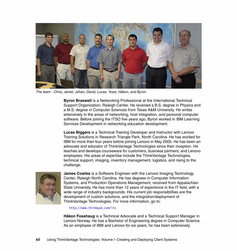
The team - Chris, Jamel, Johan, David, Lucas, Yossi, Håkon, and Byron
Byron Braswell is a Networking Professional at the International Technical Support Organization, Raleigh Center. He received a B.S. degree in Physics and a M.S. degree in Computer Sciences from Texas A&M University. He writes extensively in the areas of networking, host integration, and personal computer software. Before joining the ITSO five years ago, Byron worked in IBM Learning Services Development in networking education development.
Lucas Biggers is a Technical Training Developer and Instructor with Lenovo Training Solutions in Research Triangle Park, North Carolina. He has worked for IBM for more than four years before joining Lenovo in May 2005. He has been an advocate and educator of ThinkVantage Technologies since their inception. He teaches and develops courseware for customers, business partners, and Lenovo employees. His areas of expertise include the ThinkVantage Technologies, technical support, imaging, inventory management, logistics, and rising to the challenge.
James Cowles is a Software Engineer with the Lenovo Imaging Technology Center, Raleigh North Carolina. He has degrees in Computer Information Systems, and Production Operations Management, received from Appalachian State University. He has more than 12 years of experience in the IT field, with a wide range of industry backgrounds. His current job responsibilities are the development of custom solutions, and the integration/deployment of ThinkVantage Technologies. For more information, go to:
http://www.thinkpad.com/itc
Håkon Fosshaug is a Technical Advocate and a Technical Support Manager in Lenovo Norway. He has a Bachelor of Engineering degree in Computer Science. As an employee of IBM and Lenovo for six years, he has been extensively
xii Using ThinkVantage Technologies: Volume 1 Creating and Deploying Client Systems

involved with helping customers use and implement the ThinkVantage Technologies. His specialties include ThinkVantage tools, especially computer security, networking, and image creation and distribution. He also has in-depth technical support and counseling skills concerning future PC platforms for customers.
Johan Freidlitz is the Technical Advocate for Lenovo Sweden. He has a Bachelor of Engineering degree in Computer and Electrical Engineering. He has more than nine years of experience in the IT industry. His area of specialties include ThinkVantage, PC hardware, imaging technology, software and hardware security. He also has in-depth technical support and consulting skill. He acts as an advisor to customers and is also responsible for providing pre-sales and post-sales support and training to Lenovo internal teams and customers.
Keith Gedrose is a Lead Integration Architect for the Strategic Consulting Group at Lenovo. He has 11 years of experience within the IT industry in various leadership positions. He graduated from the University of Minnesota-Duluth with a degree in Mathematics. In 1997, Keith was outsourced to IBM Global Services and for eight years he worked in various roles supporting Prudential, and, in 1999, American Express. Job functions included team lead and technical architect for workstation imaging, software packaging, software distribution, and inventory. In October, 2004, he started in a new position with the Strategic Consulting Group consulting on workstation life cycle management utilizing the Lenovo ThinkVantage tools. He has extensive experience in all aspects of the PC life cycle.
Chris Holland is a Technical Lead in the Desktop Transformation Services team based in Sydney, Australia. He has worked for IBM for more than eight years and holds a Bachelor of Science Degree in Computing Science from the University of Technology, Sydney. His areas of expertise include the automation of operating system installations on workstation and server hardware and he has been extensively involved in the design and development of a unique and powerful build system that is now used in many of IBM Global Services' outsourced accounts in Australia.
David Kohler is a Lead Integration Architect working in the Lenovo Strategic Consulting Group. He has worked for IBM for more than three years before joining Lenovo in May 2005. He has more than 17 years of experience in the IT industry. He specializes in PC life cycle management, total cost of ownership, ThinkVantage integration implementation. He uses ThinkVantage Technologies, wireless connectivity, and security to develop architectural solutions for Lenovo customers. He completed a BSBA in Computer Information Systems from Thomas Edison State College in June 2005. He has written extensively on all of the ThinkVantage Technologies.
Preface xiii
Jamel Lynch is a Senior Consultant and IT Architect in the Lenovo Strategic Consulting Group (SCG) where he develops architectural solutions for Lenovo customers utilizing ThinkVantage Technologies. His areas of expertise include PC life cycle management, wireless, and security technology. He has more than ten years of experience in the IT and engineering industries. Prior to joining the SCG, he served as a Development Engineer in the Personal Computing Division at RTP, North Carolina, responsible for integrating emerging wireless technology into the IBM brand of ThinkPad systems. He has served as the Bluetooth Radio Frequency coexistence representative and holds several patents, including a technique that mitigates radio frequency interference between devices that operate in the 2.4Ghz spectrum. Mr. Lynch holds a B.S. degree in Electrical Engineering from the Virginia Military Institute and an M.S. degree in Electrical Engineering from the Virginia Tech College of Engineering.
Yossi Soberano is a ThinkVantage Technologies Specialist in Lenovo Israel. He has six years of experience in the personal and business computing field. His areas of expertise include most ThinkVantage Technologies, especially Client Security Solutions. He has written extensively on Access Connections and Secure Data Disposal.
Goran Wibran is a Segment Manager for Lenovo TCO and ThinkVantage Technologies, based in Research Triangle Park, NC. He helps Lenovo create solutions for cost-effective and resource-effective IT management, IT process automation, and IT system integration. He is one of Lenovo's leading experts on deploying and managing PC-based products. In his leadership role, he works with the Lenovo Development teams to create the next generation PC and Server management solutions. He also works as a consultant, helping Lenovo customers to develop and implement automated IT processes around the world.
Authors who contributed to previous editions of this redbook include:
Eleanor Howard is a Large Enterprise Field Technical Support Specialist and has worked for IBM France for over six years. She covers France, Belgium, and Luxembourg. Her areas of expertise include providing pre-sales support for ThinkCentre, the IBM Desktop range, and IBM ThinkVantage tools, in particular ImageUltra Builder. She also works with IBM Global Services to develop implementation services for customers around ThinkVantage tools.
Syed Irfan is a Senior Systems Management Professional for IBM Global Services. His areas of expertise include the development of electronic software distribution service offerings, transition management, development of electronic software delivery solutions, and project management. He has more than ten years of experience in the IT industry and is currently the team lead for Software Delivery Center. He is responsible for developing and managing multiple projects related to strategic electronic software distribution initiatives. These include electronic software distribution tools development and support, electronic
xiv Using ThinkVantage Technologies: Volume 1 Creating and Deploying Client Systems
software distribution technology evaluation, and electronic software distribution services architecture and standards development.
Ive Mattheessens is a Software Engineer with the EMEA Lenovo Imaging Technology Center, Greenock, UK, who worked on the ImageUltra solution development for international clients in the EMEA region. He has been employed with IBM/Lenovo for eight years and before joining the IBM Image Technology Center, he worked in IBM Technical Support. He specializes in system and application deployment technologies and has several years of experience with ImageUltra, Software Delivery Assistant, and Rescue and Recovery.
Dudley Miller is a Senior Systems Management Professional for IBM Global Services. He received a Bachelor of Science degree in Engineering Science from the University of Texas at Austin. He has more than 15 years of experience in the IT industry and is currently the lead architect for Software Delivery Center. His areas of expertise include object-oriented design and development and enterprise level integration of electronic software distribution tools and services. He is responsible for solution architecture, solution development, and solution deployment of electronic software distribution tools and services.
Guy Varendonck is an accredited IT Specialist in EMEA Techline located in Greenock, U.K. In his pre-sales technical support role, he has been extensively involved in supporting IBM Sales and IBM Business Partners with ThinkVantage Technologies. Before joining EMEA Techline, he worked in IBM Technical Support and Fulfillment and was Team Lead in ibm.com. He has been employed with IBM for nine years.
John Zywicki is a Systems Management Professional with Lenovo. He has 13 years of experience in all aspects of PC management, deployment, and project leadership for large enterprise accounts. He is a technical project management lead for hardware and software standardization methods, global deployments, and systems management solutions. He has coauthored three ThinkVantage Technology Redbooks. He is also responsible for providing pre-sales and post-sales support and training to Lenovo internal teams and customers.
Thanks to the following people for their contributions to this project:
Margaret TicknorTamikia BarrowJeanne TuckerInternational Technical Support Organization, Raleigh Center
Leslie ParhamInternational Technical Support Organization, San Jose
Preface xv

Ted AronStephen BalogDave BuchananRoger CameronMark GonnellaFrank KardonskiBill King IIEric NicholsonJosh NovakJeffrey WittAdam WongLenovo Research Triangle Park
Egbert GraciasJim LoebachPeter WetselDavid WallLenovo Americas TVT Customer Enablement Team
Ted BullenLenovo Salt Lake City
Thorsten StremlauLenovo EMEA TVT team
Robert PrechtelThomas ReichertMikael SchwarzmanUtimaco Safeware
Become a published authorJoin us for a two- to six-week residency program! Help write an IBM Redbook dealing with specific products or solutions, while getting hands-on experience with leading-edge technologies. You'll team with IBM technical professionals, Business Partners and/or customers.
Your efforts will help increase product acceptance and customer satisfaction. As a bonus, you'll develop a network of contacts in IBM development labs, and increase your productivity and marketability.
Find out more about the residency program, browse the residency index, and apply online at:
ibm.com/redbooks/residencies.html
xvi Using ThinkVantage Technologies: Volume 1 Creating and Deploying Client Systems
Comments welcomeYour comments are important to us!
We want our Redbooks to be as helpful as possible. Send us your comments about this or other Redbooks in one of the following ways:
� Use the online Contact us review redbook form found at:
ibm.com/redbooks
� Send your comments in an e-mail to:
� Mail your comments to:
IBM Corporation, International Technical Support OrganizationDept. HZ8 Building 662P.O. Box 12195Research Triangle Park, NC 27709-2195
Preface xvii

xviii Using ThinkVantage Technologies: Volume 1 Creating and Deploying Client Systems
Summary of changes
This section describes the technical changes made in this edition of the book and in previous editions. This edition may also include minor corrections and editorial changes that are not identified.
Summary of Changesfor SG24-7106-00for Using ThinkVantage Technologies: Volume 1 Creating and Deploying Client Systemsas created or updated on January 12, 2006.
October 2005, First EditionThis redbook is a re-write of Using ThinkVantage Tehcnologies: Volume 1 Creating and Deploying Client Systems, SG24-7045. SG24-7045 remains available on the Web for those who require documentation on previous versions of the ThinkVantage Technologies covered in this redbook.
New information� Chapter 2 - ImageUltra Builder 3.0� Chapter 3 - System Migration Assistant 5.0� Chapter 4 - Secure Data Disposal 1.3� Chapter 5 - Access Connection 3.81� Chapter 6 - Active Protection System 1.33b
Removed information� Chapter 2 - ImageUltra Builder 2.01� Chapter 3 - System Migration Assistant 4.1.3� Chapter 4 - Secure Data Disposal 1.2� Chapter 5 - Access Connection 3.30� Chapter 6 - Active Protection System 1.22
© Copyright IBM Corp. 2005. All rights reserved. xix

xx Using ThinkVantage Technologies: Volume 1 Creating and Deploying Client Systems
Chapter 1. Introduction
Over the last decade, controlling complexity has been the goal of every IT manager. With the introduction of the Internet, new devices and processes make delivery of service more complex and it has become critical for IT managers to contain costs. Understanding the total cost of ownership makes it necessary to seek methods to reduce costs while improving service.
Despite reductions in PC hardware costs, many people have seen costs rise due to increased product complexity, proliferation-related management, and support issues. Today, the initial cost of buying a PC is the “tip of the iceberg”. This emphasis on cost reductions requires ways to improve the overall PC management process.
What has Lenovo done to alleviate the stress of these costs? The company has focused research and development efforts around the challenges of reducing total cost of ownership.
Through the evaluation of each phase of the PC life cycle, Lenovo has developed a number of technologies in hardware and software to reduce IT management costs. Known as ThinkVantage Technologies, they manage the PC life cycle from pre-deploy planning through end-of-life disposition.
Figure 1-1 on page 2 shows an overview of the functions performed by various ThinkVantage Technologies during the hardware/software life cycle of a typical client PC.
1
© Copyright IBM Corp. 2005. All rights reserved. 1
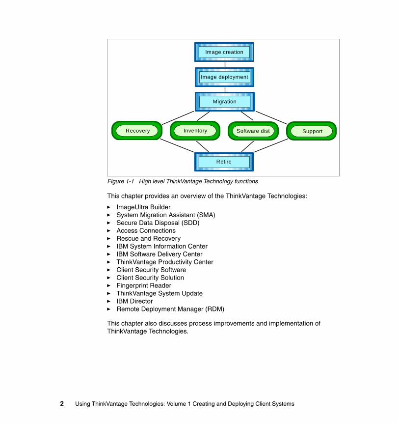
Figure 1-1 High level ThinkVantage Technology functions
This chapter provides an overview of the ThinkVantage Technologies:
� ImageUltra Builder� System Migration Assistant (SMA)� Secure Data Disposal (SDD)� Access Connections� Rescue and Recovery� IBM System Information Center� IBM Software Delivery Center� ThinkVantage Productivity Center� Client Security Software� Client Security Solution� Fingerprint Reader� ThinkVantage System Update� IBM Director� Remote Deployment Manager (RDM)
This chapter also discusses process improvements and implementation of ThinkVantage Technologies.
Image creation
Image deployment
Migration
Recovery Inventory Software dist Support
Retire
2 Using ThinkVantage Technologies: Volume 1 Creating and Deploying Client Systems
1.1 ThinkVantage TechnologiesTo address key concerns regarding cost reduction and return on investment (ROI) improvement, you can implement ThinkVantage Tools individually or as a complete solution. As a result, organizations can integrate these solutions into their existing environments to complement existing processes or develop new, more cost-efficient processes if these are not already in place.
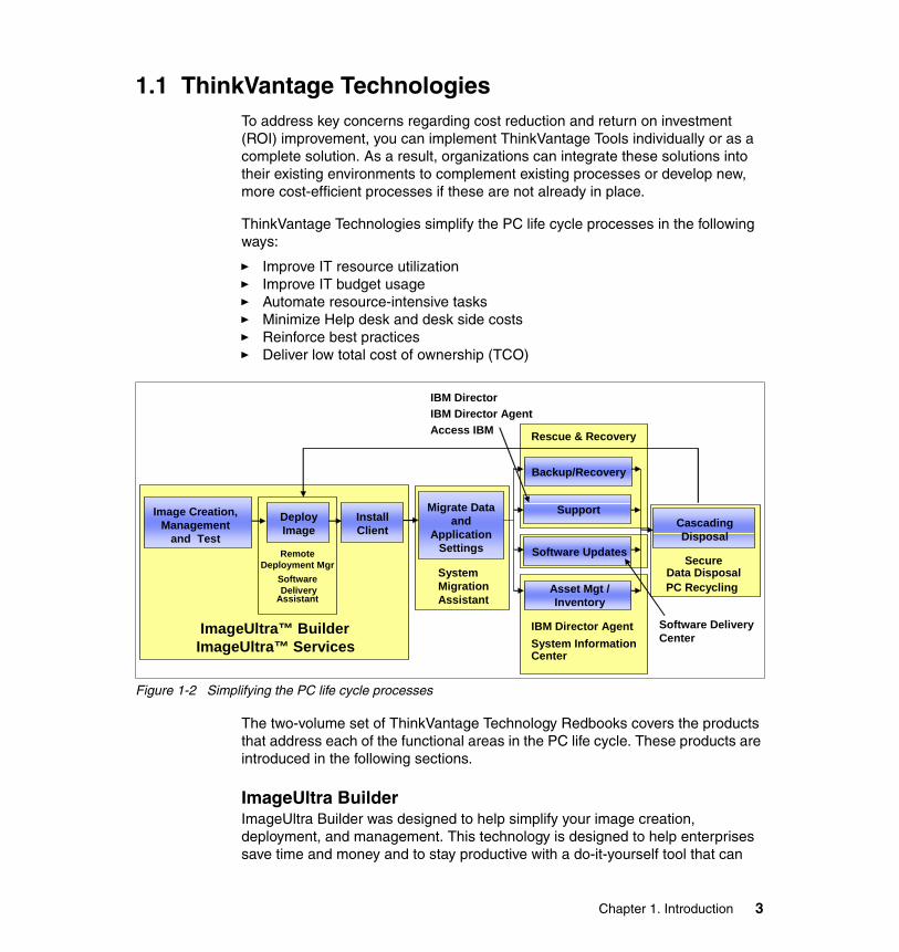
ThinkVantage Technologies simplify the PC life cycle processes in the following ways:
� Improve IT resource utilization� Improve IT budget usage� Automate resource-intensive tasks� Minimize Help desk and desk side costs� Reinforce best practices� Deliver low total cost of ownership (TCO)
Figure 1-2 Simplifying the PC life cycle processes
The two-volume set of ThinkVantage Technology Redbooks covers the products that address each of the functional areas in the PC life cycle. These products are introduced in the following sections.
ImageUltra BuilderImageUltra Builder was designed to help simplify your image creation, deployment, and management. This technology is designed to help enterprises save time and money and to stay productive with a do-it-yourself tool that can
ImageUltra™ BuilderImageUltra™ Services
Image Creation,Management
and Test
Backup/Recovery
CascadingDisposal
Install Client
Migrate Data and
Application Settings
Support
Software Updates
Asset Mgt /Inventory
SystemMigrationAssistant
IBM Director AgentSystem Information Center
Rescue & Recovery
Software DeliveryCenter
RemoteDeployment Mgr
SoftwareDelivery
Assistant
IBM DirectorIBM Director AgentAccess IBM
SecureData DisposalPC Recycling
Deploy Image
Chapter 1. Introduction 3
allow you to deploy as few as one image across your enterprise. By combining multiple languages, applications, and operating systems into a single hard drive image, you help eliminate or reduce the need for manual application installation, hardware testing, and support. This patent-pending technology lets you control your IT environment better, making deployments less painful, and lower IT costs.
ImageUltra builder allows for the separation of drivers and applications from a traditional image, unlike Symantec Ghost and PowerQuest Drive Image. By separating these components, as well as the OS, we greatly reduce the number of images that need to be kept. Since drivers and applications are updated, there is no need to open each traditional image to apply the updates. Customers already using Symantec Ghost or PowerQuest Drive Image can incorporate their images into ImageUltra Builder as either semi-portable or system-specific images.
For more information regarding ImageUltra Builder, see Chapter 2, “ImageUltra Builder” on page 13.
System Migration Assistant (SMA)System Migration Assistant enables custom settings, preferences, and data to be migrated from a user's former PC to the new PC accurately, efficiently, and effectively. When older computers are refreshed or new computers are introduced, moving user data and system settings to the new system becomes expensive and time-consuming. Removing the problems associated with migration is an important customer satisfaction issue.
SMA is discussed in Chapter 3, “System Migration Assistant” on page 179.
Secure Data Disposal (SDD)Secure Data Disposal removes all data on a hard disk drive, protecting sensitive information when a drive is re-deployed or retired. After using this process, data will be non-recoverable.
SDD is discussed in Chapter 4, “Secure Data Disposal” on page 263.
Access ConnectionsAccess Connections is a connectivity assistant program for your ThinkPad computer that allows you to create and manage location profiles. Each location profile stores all of the network and Internet configuration settings that are necessary to connect to a network infrastructure from a specific location such as home or work. By switching between location profiles as you move your computer from place to place, you can quickly and easily connect to a network without having to manually reconfigure your settings and restart your computer each time.
4 Using ThinkVantage Technologies: Volume 1 Creating and Deploying Client Systems
Access Connections is discussed in Chapter 5, “ThinkVantage Access Connections” on page 275.
Rescue and Recovery Rescue and Recovery is a one-button solution that includes a set of self recovery tools to help users diagnose, get help, and recover from a software crash, even if the primary operating system will not boot. It helps with everything from complete software failure to occasions when you need only to restore a corrupted or deleted file. And it is easily accessible from the Microsoft® Windows® desktop or by pressing the blue Access IBM button on supported Lenovo/IBM systems (or the F11 key on other personal computers).
For more information regarding Rescue and Recovery, refer to ThinkVantage Technologies: Volume 2 Maintaining and Recovering Client Systems, SG24-7107.
IBM System Information CenterSystem Information Center is a cost and resource-effective inventory solution that complements and leverages the customer’s investment in ThinkVantage Technologies. Features included in System Information Center are easy browser accessibility, minimal resource usage, control of software license management, and central management.
IBM System Information Center is discussed in ThinkVantage Technologies: Volume 2 Maintaining and Recovering Client Systems, SG24-7107.
IBM Software Delivery CenterSoftware Delivery Center is a Java™-based Web-enabled software distribution solution that complements and leverages the customer’s investment in ThinkVantage Technologies. Software Delivery Center uses industry standard components, is simple to manage, easily integrates into an existing customer network infrastructure, is customizable, and is cost-effective both at the time of implementation and over the long term.
IBM Software Delivery Center is discussed in ThinkVantage Technologies: Volume 2 Maintaining and Recovering Client Systems, SG24-7107.
ThinkVantage Productivity CenterProductivity Center guides you to a host of information sources and tools. With one push of the blue button, Productivity Center helps you set up, understand, and enhance your ThinkPad notebook or ThinkCentre desktop. The Away Manager application allows you to preselect and run routine tasks to maintain your system's performance. Productivity Center also provides easy access to additional ThinkVantage Technologies, including:
Chapter 1. Introduction 5
� Rescue and Recovery� Client Security Solution� Access Connections� System Update� System Migration Assistant
For more information regarding ThinkVantage Productivity Center, refer to ThinkVantage Technologies: Volume 2 Maintaining and Recovering Client Systems, SG24-7107.
Client Security SoftwareClient Security Software is a component of the Embedded Security Subsystem (ESS), available on select Lenovo/IBM computers. ESS consists of the integrated security chip and Client Security Software (download required). Working together, these components provide security not previously available. The integrated security chip provides hardware-based protection of critical security information, including passwords, encryption keys, and electronic credentials. The security software provides the interface between security-aware applications and the functionality of the chip. In addition, it provides support for peripheral security devices that control access to the PC itself.
For more information regarding Client Security Software, refer to ThinkVantage Technologies: Volume 2 Maintaining and Recovering Client Systems, SG24-7107.
Client Security SolutionClient Security Solution helps protect your company information, including vital security information such as passwords, encryption keys and electronic credentials, while helping to guard against unauthorized user access to data. It works in conjunction with an embedded Trusted Platform Module (TPM) chip (on select ThinkPad and ThinkCentre machines) to manage encryption keys and processes. Client Security Solution password manager helps you consolidate the multiple passwords a user may have down to either just one, or down to a single swipe of their finger when using Client Security Solution password manager with a fingerprint reader.
For more information regarding Client Security Software, refer to ThinkVantage Technologies: Volume 2 Maintaining and Recovering Client Systems, SG24-7107.
Fingerprint ReaderFingerprint Reader hardware reduces the complexity of maintaining dozens of passwords, while at the same time enhancing security in combination with a password. Fingerprint reader hardware is available in a number of formats:
6 Using ThinkVantage Technologies: Volume 1 Creating and Deploying Client Systems
Select ThinkPad Notebooks, USB keyboard with integrated fingerprint reader, and USB fingerprint reader. ThinkVantage Fingerprint Reader software and its components work with the Fingerprint Reader making it both simpler and safer to prove who you are to your system. The fingerprint reader solution can be used either to simplify logon or as additional security.
For more information on the Fingerprint Reader software, refer to ThinkVantage Technologies: Volume 2 Maintaining and Recovering Client Systems, SG24-7107.
ThinkVantage System UpdateThinkVantage System Update (TVSU) is a new tool that keeps your Think system up to date with the latest Lenovo downloads. ThinkVantage System Update accesses, downloads, and installs updates for drivers, firmware, BIOS, and software on ThinkPad and ThinkCentre systems.
ThinkVantage System Update replaces the IBM Update Connector™ as the utility for automatically updating your PCs. TVSU resembles the look and feel of the Windows Update user interface.
TVSU also provides a ThinkVantage Technology Active Update feature that allows the user to request updates for specific ThinkVantage Technologies.
For more information on ThinkVantage System Update, refer to ThinkVantage Technologies: Volume 2 Maintaining and Recovering Client Systems, SG24-7107.
IBM DirectorIBM Director V5.10 is the newest release of the industry-leading client/server workgroup manager. IBM Director’s tools provide customers with flexible capabilities to realize maximum system availability and lower IT costs. With IBM Director, IT administrators can view and track the hardware configuration of remote systems in detail and monitor the usage and performance of critical components, such as processors, disks, and memory.
IBM Director V5.10 is discussed in Implementing Systems Management Solutions using IBM Director, SG24-6188.
Remote Deployment ManagerRemote Deployment Manager (RDM) provides tools to simplify configuration and deployment of operating systems and applications. Adding a computer to the RDM database allows for remote installation, maintenance, and software updates on client computers.
Chapter 1. Introduction 7

1.2 ThinkVantage Technologies process improvementsUsing the ThinkVantage Tools can help optimize the PC life cycle to enhance current processes. The two volumes of Using ThinkVantage Tools are divided into creation/deployment and maintenance/recovery of the ThinkVantage Technologies. The tools discussed in these Redbooks are key contributors in deployment optimization. ThinkVantage Technologies allow PCs to be more than just clients.
ThinkVantage Technologies provide optimization and cost avoidance solutions for the following:
� Simplified image complexity by delivering a hardware-independent imaging solution
� Improved application deployment by delivering a detached application deployment solution
� Rapid transition by delivering a smooth data migration solution
� “Down the Wire” recovery by delivering a managed system recovery and backup solution
� Life cycle ends with data removal by delivering a Secure Data Disposal solution
� Additional solutions for security, deployment, management, support, wireless, and more.
Many organizations will relate to Figure 1-3 for each part of the processes we define. Implementation of the ThinkVantage Technologies will help reduce costs and offer opportunities for companies as illustrated below.
8 Using ThinkVantage Technologies: Volume 1 Creating and Deploying Client Systems
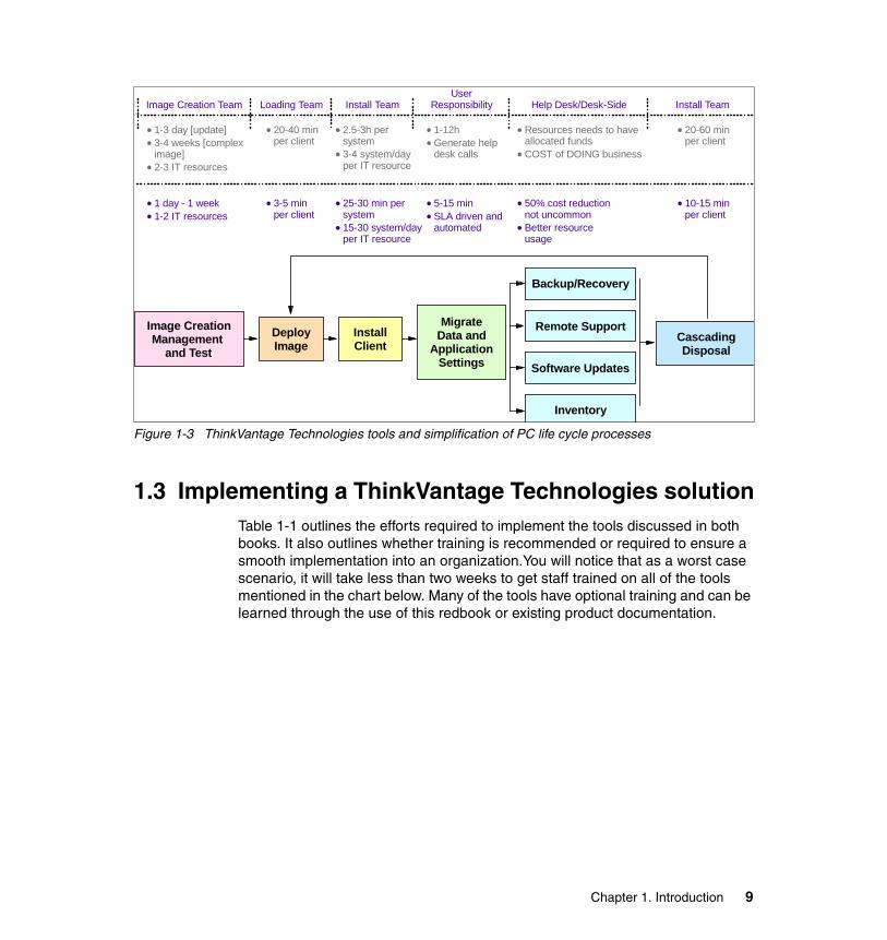
Figure 1-3 ThinkVantage Technologies tools and simplification of PC life cycle processes
1.3 Implementing a ThinkVantage Technologies solutionTable 1-1 outlines the efforts required to implement the tools discussed in both books. It also outlines whether training is recommended or required to ensure a smooth implementation into an organization.You will notice that as a worst case scenario, it will take less than two weeks to get staff trained on all of the tools mentioned in the chart below. Many of the tools have optional training and can be learned through the use of this redbook or existing product documentation.
Image Creation Team Loading Team Install TeamUser
Responsibility Help Desk/Desk-Side Install Team
1-3 day [update]3-4 weeks [compleximage]2-3 IT resources
20-40 minper client
2.5-3h persystem3-4 system/dayper IT resource
1-12hGenerate helpdesk calls
Resources needs to haveallocated fundsCOST of DOING business
20-60 minper client
1 day - 1 week1-2 IT resources
3-5 minper client
25-30 min persystem15-30 system/dayper IT resource
5-15 minSLA driven andautomated
50% cost reductionnot uncommonBetter resource usage
10-15 minper client
Image CreationManagement
and TestDeployImage
InstallClient
MigrateData and
ApplicationSettings
Backup/Recovery
Remote Support
Software Updates
Inventory
CascadingDisposal
Chapter 1. Introduction 9
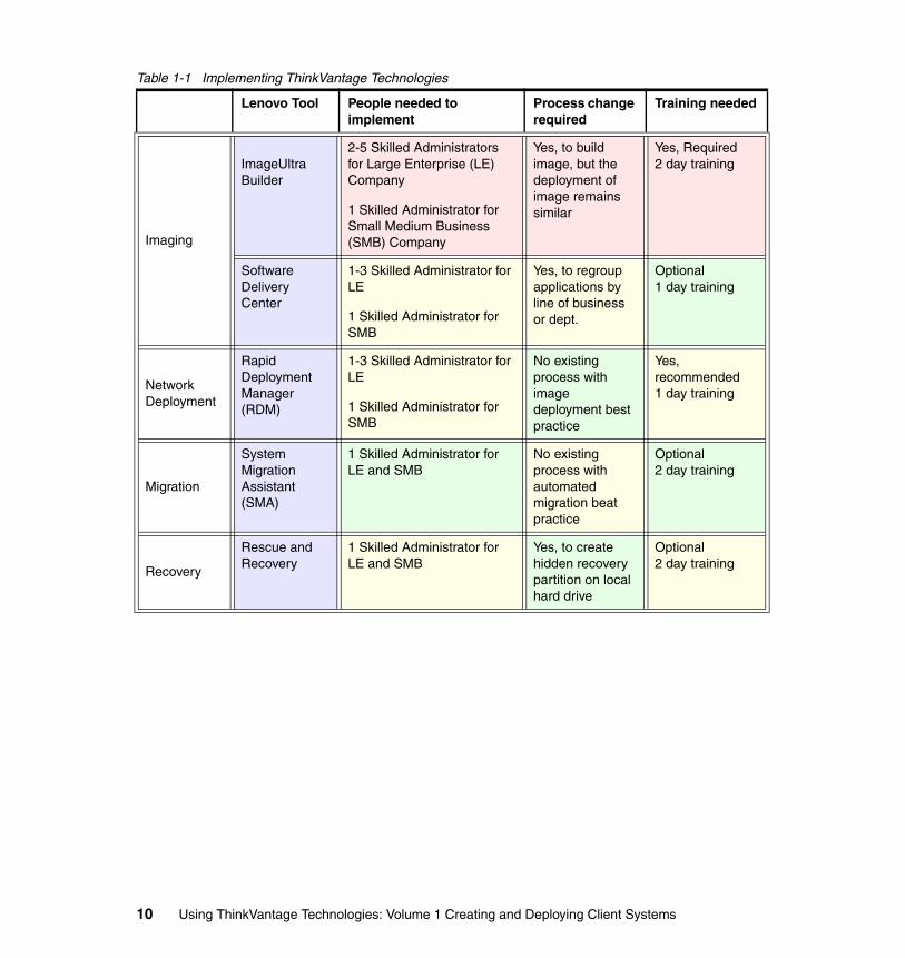
Table 1-1 Implementing ThinkVantage Technologies
Lenovo Tool People needed to implement
Process change required
Training needed
Imaging
ImageUltra Builder
2-5 Skilled Administrators for Large Enterprise (LE) Company
1 Skilled Administrator for Small Medium Business (SMB) Company
Yes, to build image, but the deployment of image remains similar
Yes, Required2 day training
Software Delivery Center
1-3 Skilled Administrator for LE
1 Skilled Administrator for SMB
Yes, to regroup applications by line of business or dept.
Optional 1 day training
NetworkDeployment
Rapid Deployment Manager (RDM)
1-3 Skilled Administrator for LE
1 Skilled Administrator for SMB
No existing process with image deployment best practice
Yes, recommended 1 day training
Migration
System Migration Assistant (SMA)
1 Skilled Administrator for LE and SMB
No existing process with automated migration beat practice
Optional 2 day training
Recovery
Rescue and Recovery
1 Skilled Administrator for LE and SMB
Yes, to create hidden recovery partition on local hard drive
Optional 2 day training
10 Using ThinkVantage Technologies: Volume 1 Creating and Deploying Client Systems
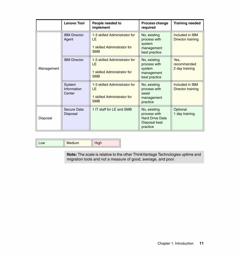
Management
IBM Director Agent
1-3 skilled Administrator for LE
1 skilled Administrator for SMB
No, existing process with system management best practice
Included in IBM Director training
IBM Director 1-3 skilled Administrator for LE
1 skilled Administrator for SMB
No, existing process with system management best practice
Yes, recommended 2 day training
System Information Center
1-3 skilled Administrator for LE
1 skilled Administrator for SMB
No, existing process with asset management practice
Included in IBM Director training
Disposal
Secure Data Disposal
1 IT staff for LE and SMB No, existing process with Hard Drive Data Disposal best practice
Optional 1 day training
Low Medium High
Lenovo Tool People needed to implement
Process change required
Training needed
Note: The scale is relative to the other ThinkVantage Technologies uptime and migration tools and not a measure of good, average, and poor.
Chapter 1. Introduction 11

12 Using ThinkVantage Technologies: Volume 1 Creating and Deploying Client Systems
Chapter 2. ImageUltra Builder
IT departments face the demanding task of building workstations for their users in a consistent manner in order to simplify supporting all of these workstations. Traditionally, IT departments have accomplished this using monolithic images, cloned from one system, and then deployed to many. There are a number of inherent problems you face when using traditional images. One issue is that business units within an organization often have a variety of application requirements. Another challenge is that traditional images often only work on hardware that is very similar to the original computer used to create the image. These two factors usually force the creation of multiple images. Multiple images, in combination with varying application requirements, make managing the environment time consuming, expensive, and prone to error.
ImageUltra Builder (IUB) is an image management solution intended for use by IT departments. Its processes are designed to alleviate many of the issues associated with traditional imaging. ImageUltra Builder uses a modular architecture for image creation that ensures it isolates individual components (such as applications or drivers), but at the same time, ImageUltra Builder also allows you to isolate and easily modify these individual components.
This chapter describes the ImageUltra Builder concepts and components, how to install and use ImageUltra Builder. We discuss how to integrate ImageUltra Builder with other tools, including LANDesk Management Suite for ThinkVantage Technologies.
2
© Copyright IBM Corp. 2005. All rights reserved. 13
The following topics are covered in this chapter:
� 2.3, “ImageUltra Builder components and basic operation” on page 19
� 2.4, “ImageUltra Builder installation and setup” on page 26
� 2.5, “Module options and usage” on page 39
� 2.6, “Smart Image types” on page 67
� 2.7, “Preparing the repository for Smart Image creation” on page 73
� 2.8, “Hardware-Specific Image” on page 78
� 2.9, “Portable-Sysprep Image” on page 99
� 2.10, “Ultra-Portable Image” on page 123
� 2.11, “Deploy and install with ImageUltra Builder” on page 144
� 2.12, “ThinkVantage integration considerations” on page 173
Appendix A, “Smart Image deployment using third party tools” on page 373, documents how ImageUltra Builder integrates with third party tools such as Microsoft Remote Installation Services (RIS), Symantec Ghost, and Symantec DeployCenter.
14 Using ThinkVantage Technologies: Volume 1 Creating and Deploying Client Systems
2.1 IntroductionThe purpose of ImageUltra Builder is to provide a development environment that allows a small number of technical staff to develop and maintain system builds with the least potential for human error. ImageUltra Builder includes a deployment feature as a means to test builds and for production deployment of small numbers of simultaneous deployments. ImageUltra Builder is designed to work with system deployment solutions such as Symantec Ghost, not replace them.
ImageUltra Builder is primarily a development and system testing solution. Direct deployment of an IUB solution is possible, but is not practical in large enterprise environments.
A best practice use of IUB is to leverage it for creating, testing, and maintaining system builds. A traditional image cloning utility or LANDesk Management Suite is then used to deploy the resulting image during a mass rollout of systems.
ImageUltra Builder does offer a good direct deployment solution for rebuilding systems either directly via a network deploy or standalone from a previously deployed service partition. Utilizing the network sync capability of ImageUltra Builder insures that the deployed solution is up to date with the tested production repository.
2.1.1 What’s new with ImageUltra Builder 3.0?IUB 3.0 is the first major update to IUB in the past four years. The familiar, easily navigated administrator interface remains the same. Much of the underlying technologies have been replaced to make the solution more robust.
Key changes� Windows Preinstallation Environment (PE)-based deployment instead of IUB
2.x's DOS solution.
Important:
The typical definition of an “image” is a compressed single file snapshot of an entire system that you use to clone one system and deploy to many.
In this document and in the ImageUltra Builder 3.0 User’s Guide, we use the term “image” to describe a dynamic modular build process. This ImageUltra Builder solution enables IT departments to create new systems from a repository of individual components for OS, drivers, applications, and patches.
Chapter 2. ImageUltra Builder 15
� Cloudscape™ SQL database for IUB administrator environment replaces the IUB 2.x's Microsoft Access file-based database.
� The use of a new boot loader on the ImageUltra deploy media that allows the install process to continue without requiring the user to remove or deploy media.
� The new Migrate Repository Wizard that takes users through the different stages to migrate from a previous version of an ImageUltra repository.
� Native NTFS support eliminates the need for NTFS conversion during install.
� WinPE-based interface replaces current DOS-based DOE menus.
� More robust graphics, fonts, mouse support, and customer logos.
� Customizable client GUI features.
� Deployment speed for first boot has been improved.
� Features not supported by DOS:
– New network cards– Large HDDs– Longhorn support requires WinPE– No longer able to license Microsoft DOS after Fourth Quarter 2004
� Integration with Rescue and Recovery 3.0 environment (WinPE-based)
Items of which to be aware � Ultra™ Portable Images utilize the Microsoft sysprep factory utility.
� Most IUB 2.x modules can be imported and used in the IUB 3 build process. Any DOS dependent modules cannot be used in IUB 3.x.
� DMCLEAN.cmd and DDREMOVE.exe, while still useful in creating Portable-Sysprep Images, are not supplied with this version of IUB.
� IUB 3 uses a UNC path to the repository share. A functioning network connection must be present to be able to open the repository even if it is on the same system as the administrator interface.
� You can choose to import from your previous IUB repositories, or you can choose to migrate it.
� Migration creates a new repository in the Cloudscape server and assigns the repository files to the location of the previous repository.
� Once a repository is migrated, the previous version of the IUB can no longer use it.
16 Using ThinkVantage Technologies: Volume 1 Creating and Deploying Client Systems
2.2 Image management
This section compares and contrasts traditional systems build solutions to the more efficient ImageUltra Builder solution.
An image consists of several components: an operating system, applications, device drivers, and other related files necessary to run a computer successfully. In most cases, Information Technology (IT) departments create images on source computers, capture snapshots of these computers, and store them in a central location. This snapshot (commonly referred to as an image) is then deployed to multiple computers either across a network or from a set of image CDs. This enables an IT department to develop standardized images and control the versions of software and device drivers used throughout their company.
ImageUltra Builder provides a mechanism to modularize and group components. Operating systems, applications, and drivers become individual components known as modules that are then grouped using maps. A map describes one or more complete installations by listing all the required modules. You can update or maintain each module without having to modify or recreate the entire image. It is this modular approach that allows ImageUltra Builder to simplify image creation, maintenance, and deployment. We refer to images constructed from maps and modules as Smart Images.
We store all maps and modules in a repository.
2.2.1 Traditional tools and processes for building systemsWe describe two of the fundamental techniques for creating an automated workstation installation below. We list each technique with its pros and cons.
Unattended installation: Scripted This is the process of building a system using scripts that remove the need for user interaction during the install process. A technician initiates the installation, but then scripts provide the answers to all the questions typically answered by the person installing the computer. Microsoft provides a supported mechanism to automate the operating system installation using a script file called unattend.txt. All applications and drivers that are required for the installation also need to be automated to install without user interaction. Application installs need to be automated using third party tools or application specific methods.
� Pros:
– Provides consistency of workstation installs.– You can use CDs, DVDs, or over the network to handle remote install. – This is a quick way to make small changes to individual components.
Chapter 2. ImageUltra Builder 17
– Provides clean long term maintenance (the image should not degrade over time).
– Can support a wide variety of hardware and is not Hardware Abstraction Layer (HAL) dependent.
– Uses the vendor’s supported installation mechanism.
� Cons:
– May take hours to install.– Requires advanced technical knowledge to create and maintain scripts.– High bandwidth used during network installation.– Requires an additional solution to install applications and drivers that not
included with the operating system.
Disk duplication: Cloning Many organizations use third party cloning utilities to create and deploy their images. First, you install and configure a master computer as required, then you use a third party cloning tool to capture an image of the hard disk. Then you load that image onto many other computers within the corporate environment.
� Pros:
– Provides consistency of workstation installs.– Can be installed using CDs, DVDs, or over the network.– Is a fast installation.– You can install using multicasting to reduce network load when installing
many machines simultaneously.
� Cons:
– Image files are time consuming to maintain.– Image quality can degrade over time as components are continually added
or removed.– Images are Hardware Abstraction Layer (HAL) dependent and cannot be
shared between machines with major chipset differences.– Third party imaging tools are required for creating and deploying images.– Image can grow in size due to inclusion of many drivers not required for all
target systems.
2.2.2 Image complexity leads to image management problemsKeeping and maintaining images can quickly become very difficult as organizations become more complex. The number of languages, hardware
Note: Microsoft supports cloning when used in conjunction with sysprep. For technical information about sysprep, see Appendix A.1, “Sysprep hardware limitations and HALs” on page 374.
18 Using ThinkVantage Technologies: Volume 1 Creating and Deploying Client Systems
types, and operating systems can increase the number of images exponentially, making it difficult to maintain images.
The major challenges faced by IT departments include:
� Goals to meet:
– Reducing time required to create and test images. Departments have varying application and configuration requirements. Difficulties managing these variations often result in manual installation of applications by IT staff.
– Finding ways to build and deploy images across a wider range of hardware.
– Reducing or minimizing the total number of images that have to be maintained.
� Issues to overcome:
– Use of multiple operating systems increases deployment and Help desk costs and support for multiple languages required by large multinational companies increases complexity and cost of large rollouts.
– IT groups external to the team tasked with image maintenance make unauthorized modifications to the standard images, generating increased Help desk calls and requiring additional IT time to re-image PCs.
– Over time, images have to be updated or rebuilt from scratch.
2.3 ImageUltra Builder components and basic operation
This section describes the various processes and components associated with the ImageUltra Builder program. For additional step-by-step instructions about how to complete any of the processes described in this chapter, refer to the ImageUltra Builder built-in Help system by pressing F1 or refer to the ImageUltra
Chapter 2. ImageUltra Builder 19
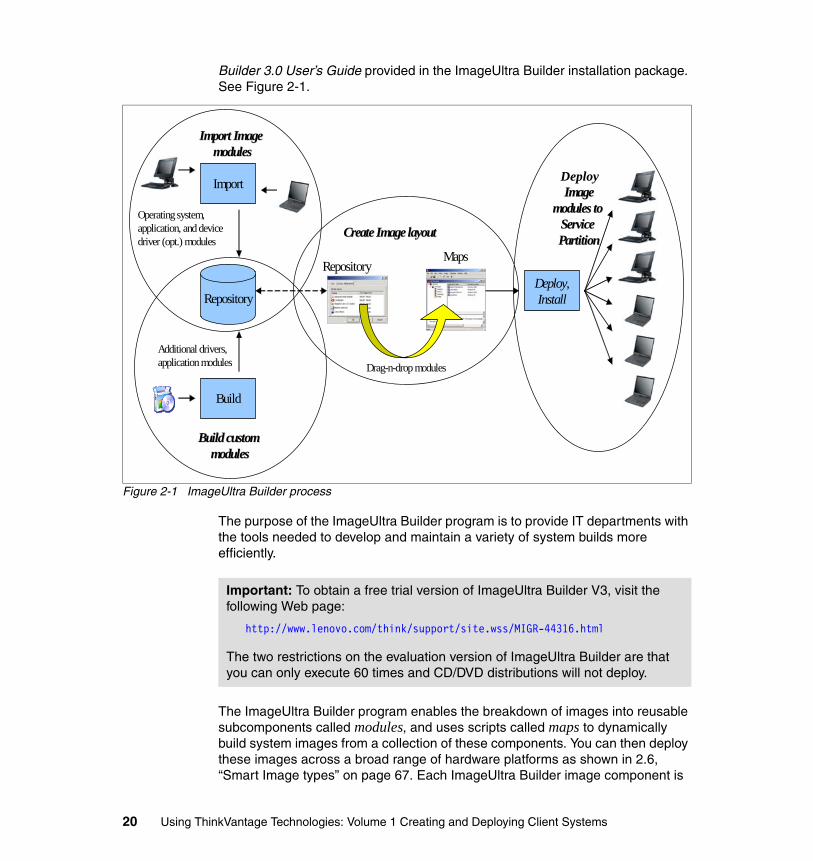
Builder 3.0 User’s Guide provided in the ImageUltra Builder installation package. See Figure 2-1.
Figure 2-1 ImageUltra Builder process
The purpose of the ImageUltra Builder program is to provide IT departments with the tools needed to develop and maintain a variety of system builds more efficiently.
The ImageUltra Builder program enables the breakdown of images into reusable subcomponents called modules, and uses scripts called maps to dynamically build system images from a collection of these components. You can then deploy these images across a broad range of hardware platforms as shown in 2.6, “Smart Image types” on page 67. Each ImageUltra Builder image component is
Repository
Import
Build
Deploy,Install
Import Image Import Image modulesmodules
Build custom Build custom modulesmodules
Operating system, application, and device driver (opt.) modules
Additional drivers,application modules
RepositoryMaps
Drag-n-drop modules
DeplyDeplyImageImage
modules to modules to Service Service PartitionPartitionCreate Image layout Create Image layout
Deploy
Important: To obtain a free trial version of ImageUltra Builder V3, visit the following Web page:
http://www.lenovo.com/think/support/site.wss/MIGR-44316.html
The two restrictions on the evaluation version of ImageUltra Builder are that you can only execute 60 times and CD/DVD distributions will not deploy.
20 Using ThinkVantage Technologies: Volume 1 Creating and Deploying Client Systems
stored in a central location called a repository. ImageUltra Builder creates and uses a hidden service partition for deployment. The service partition contains different modules for the operating system, applications, and device drivers, as well as a set of recovery tools. The service partition provides its own operating environment which is not dependent on the presence of a functioning Windows operating system. Use this to recover a system.
2.3.1 ImageUltra Builder terminologyThe following are high-level descriptions of some of the ImageUltra Builder terms used in this chapter:
� Base Map
Defines the menu structure and modules (operating systems and applications) contained in a Smart Image.
A base map contains only the operating systems, add ons, partitioning, and application modules that are required for a unique deployment. This can be accessed through the Base Maps tab in the ImageUltra Builder application (see Figure 2-36 on page 74). The base map is used to organize modules for deployment to install by language, business unit, or any other business specific map that was created.
� Build
To compress the source files for a module into a single file. This prepares the module to for use in a map.
� Container
Special type of module that groups or contains other modules. All modules within the container must be of the same type.
� Deploy
Deploy is the preparation phase of an ImageUltra Builder install. The deploy phase copies all required maps and modules to the service partition of the computer in preparation for the install phase.
Deploy is also an applet that is used to create CDs used for network or CD/DVD deployments.
� Driver Map
Defines the device driver modules contained in a Smart Image.
A driver map is the menu-driven area that contains all of the driver modules. Access this through the Driver Map tab in the ImageUltra Builder application (see Figure 2-36 on page 74). Use this to insert all the driver modules for a model specific system under one map heading. The ThinkPad T40 2373-75U driver map, for example, can contain the audio, video, and network driver
Chapter 2. ImageUltra Builder 21
modules. You can set this up to display either a manual menu selection window during installation or you can add a a filter to automatically select which drivers the system requires.
� Dynamic Operating Environment (DOE)
This part of ImageUltra Builder is customized via the Maps. DOE provides a means of customizing the build process at the time of deployment. The typical use of DOE is to offer different languages and groups of applications for particular target systems.
� Export
Exports maps or modules from a repository to an archive directory.
� Filter
Runs during the installation process and enables automated decisions. Filters are Win32® command-line environment programs that have a true or false return value.
� Gold module
A module that has been finalized and locked so that no further changes can be made to it.
� Hardware Independent Imaging Technology (HIIT)
Intelligently detects the correct driver map to install for ThinkPad and ThinkCentre systems.
� Hardware-Specific Image (HSI)
An ImageUltra Builder image type that contains a copy of a Traditional Image (TI) that can be deployed using an IUB map. This image type cannot be combined with any additional modules. This type of image is used primarily as a transition step in the process of creating a Portable-Sysprep Image. The HSI enables existing images to be added to ImageUltra with no modifications. But the resulting image will not benefit from any of the valuable features, such as modularity, offered by IUB. A Hardware-Specific Image can be used to create images for operating systems not supported by the other IUB image types.
Supported operating systems
– Windows 95– Windows 98
Tip: For a list of ThinkPad and ThinkCentre HIIT-enabled personal computers, visit the ImageUltra Web site at:
http://www.lenovo.com/think/support/site.wss/MIGR-44316.html
22 Using ThinkVantage Technologies: Volume 1 Creating and Deploying Client Systems
– Windows Millennium– Windows NT®– Windows 2000– Windows XP Home– Windows XP Media Center– Windows XP Professional– Windows XP Tablet
� Hidden Protected Area (HPA)
A now obsolete hidden area on the hard disk available on a small number of ThinkPad and ThinkCentre models. The Hidden Protected Area, also referred to as PARTIES (Protected Area Runtime Interface Extension Services area), provides a flexible disk-based recovery solution that enhances the security for recovery data and diagnostics. The service partition (SP) provides this functionality on all current ThinkPad and ThinkCentre systems.
� Import
Imports maps or modules from another source into the repository. This source can be a set of ThinkPad and ThinkCentre Recovery CDs, a directory, another repository, a service partition, or HPA partition.
� Module
A reusable compressed, self-contained installation package that you can combine with other modules in the repository to make one or more images. Each application, device driver, and operating system is a module.
– Base operating system modules: These modules contain all of the components that are part of the base operating system. Base operating system modules include modules created from Hardware-Specific Images and Portable-Sysprep Images, as well as base operating-system modules imported from the service partition or Hidden Protected Area of ThinkPad and ThinkCentre systems. Base operating system modules are typically created by and installed using an imaging tool such as Symantec Ghost or Symantec DeployCenter. An example of this is an operating system module for Window 2000 or Windows XP. See “Hardware-Specific Image” on page 78 for a detailed example showing how an operating system module is prepared.
– Operating system add-on modules: These modules include items such as operating-system hot fixes, service packs, patches, and updates that install through a standard setup process, similar to applications.
– Partitioning modules: These modules add or remove hard disk partitions. There can be multiple partitioning modules in a base map to accomplish various results. When using a partitioning module to create additional partitions that include data, the module contains all of the information required to create the additional partition and all of the data to be placed in the partition. These types of partitioning modules are typically
Chapter 2. ImageUltra Builder 23
created using an imaging tool, such as Symantec Ghost or Symantec DeployCenter.
– Application modules: Each of these modules contains all of the components associated with a specific application. Software applications such as Microsoft Office, Adobe Acrobat, and System Migration Assistant would each be separate application modules. See 2.5.7, “Creating custom modules” on page 47.
– When building an Ultra-Portable Image or a Portable-Sysprep Image, application modules may be added.
– When building a Hardware-Specific Image, no application modules can be used. All applications must be included within the Hardware-Specific Image when it is created.
– Device driver modules: Each of these modules contains all of the components associated with a specific device driver. Device drivers are grouped into driver maps and the driver map is selected during the deployment phase. This enables device driver modules and driver maps to be maintained independently of the operating system and application content defined in the base maps.
� Network Sync
Network synchronization occurs during deployment when the base and driver maps are selected, and again at installation time when the maps are executed. This allows a client with a Smart Image to compare maps from deployment media or a local service partition to the server repository. If updated maps are available, they will be copied to the system running the ImageUltra Builder installation. All modules contained in the maps will be compared with the repository’s maps to insure that the newest maps and modules are deployed.
� Portable-Sysprep Image (PSI)
An ImageUltra Builder image uses an operating system module created by a third-party image-cloning tool, such as Symantec Ghost or Symantec DeployCenter. Before an image of the seed system is taken, the ImageUltra Builder Customization Program (IUBCP.exe) is run on it. This program installs hooks into the system that allow the IUB process to continue after the
Important: All of the operating system, device driver, and application modules used to build each specific ThinkPad and ThinkCentre system during manufacturing are loaded on the service partition. These gold modules can be imported from the service partition or from a set of recovery CDs. These modules enable the creation of an image that can be used across a ThinkPad or ThinkCentre product line of Hardware Independent Imaging Technology-enabled (HIIT-enabled) personal computers.
24 Using ThinkVantage Technologies: Volume 1 Creating and Deploying Client Systems
third-party cloning tool has laid down the image. IUB is then able to install additional modules on top of the cloned image. This provides flexibility for device driver, application, and operating system updates to be applied at the time of deployment. The PSI utilizes the DOE and HIIT technologies.
Supported operating systems
– Windows 2000– Windows XP Home– Windows XP Media Center– Windows XP Professional– Windows XP Tablet
� Promote
Used after a map or module has been thoroughly tested and is ready for production. Once a module is promoted to the gold state, it is locked so it can no longer be edited. Promoting a module to the gold state ensures that the module will not be changed accidentally.
� Repository
Contains all the ImageUltra Builder maps and modules necessary to build a Smart Image.
� Service Partition
A hidden partition on a system for storing the ImageUltra Builder maps, modules, and recovery operating system.
� Smart Image
An image that includes intelligence to dynamically configure itself based on operating system, language, hardware configuration, and user application sets.
� Traditional Image (TI)
A monolithic snapshot of a seed system that is copied to other systems. It is neither dynamic nor flexible and can generally only be used on identical or very similar hardware models.
� Utility
Utilities are Win32 command-line programs that run during the installation process, either immediately before the installation menu, as a result of specific menu selections, or after the menu. To use a utility, either assign a utility module to a base map menu item or use the Before/After Menu tab in the Map Settings window for base maps.
Chapter 2. ImageUltra Builder 25
� Ultra-Portable Image (UPI)
This type of image will deploy a Windows operating system utilizing the unattended build process. Then, additional device drivers, applications, operating system patches, and custom scripts will be applied. This type of image provides the greatest flexibility, supports multiple Hardware Abstraction Layers (HALs), and is the easiest to update.
Supported operating systems
– Windows 2000– Windows XP Home– Windows XP Media Center– Windows XP Professional– Windows XP Tablet
2.4 ImageUltra Builder installation and setup
We cover the installation and basic repository administration of ImageUltra Builder in the following sections:
� 2.4.1, “Installation” on page 27
� 2.4.2, “Repository and user administration” on page 29
The following sections then detail the creation and management of modules and Smart Images:
� 2.6, “Smart Image types” on page 67
� 2.8, “Hardware-Specific Image” on page 78
� 2.9, “Portable-Sysprep Image” on page 99
� 2.10, “Ultra-Portable Image” on page 123
Once you complete these steps above, you may deploy the Smart Image to the target systems. ImageUltra Builder was designed to work with system deployment solutions such as Symantec Ghost, not replace them. Refer to 2.11, “Deploy and install with ImageUltra Builder” on page 144, to learn how to deploy from the ImageUltra Builder repository directly, and refer to Appendix A, “Smart Image deployment using third party tools” on page 373, to learn how to leverage third party solutions for deployment of an ImageUltra Builder-developed build.
Note: Since the ImageUltra Builder V3 deployment process is Microsoft Windows PE-based, ImageUltra Builder does not support DOS utilities. The ImageUltra Builder program does not provide any utilities.
26 Using ThinkVantage Technologies: Volume 1 Creating and Deploying Client Systems
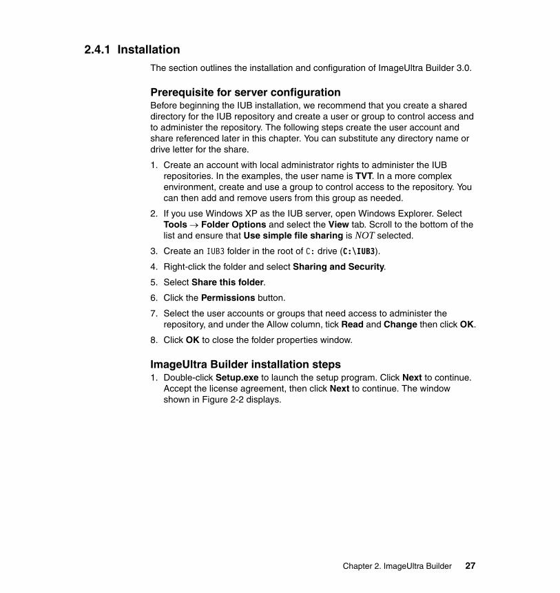
2.4.1 InstallationThe section outlines the installation and configuration of ImageUltra Builder 3.0.
Prerequisite for server configurationBefore beginning the IUB installation, we recommend that you create a shared directory for the IUB repository and create a user or group to control access and to administer the repository. The following steps create the user account and share referenced later in this chapter. You can substitute any directory name or drive letter for the share.
1. Create an account with local administrator rights to administer the IUB repositories. In the examples, the user name is TVT. In a more complex environment, create and use a group to control access to the repository. You can then add and remove users from this group as needed.
2. If you use Windows XP as the IUB server, open Windows Explorer. Select Tools → Folder Options and select the View tab. Scroll to the bottom of the list and ensure that Use simple file sharing is NOT selected.
3. Create an IUB3 folder in the root of C: drive (C:\IUB3).
4. Right-click the folder and select Sharing and Security.
5. Select Share this folder.
6. Click the Permissions button.
7. Select the user accounts or groups that need access to administer the repository, and under the Allow column, tick Read and Change then click OK.
8. Click OK to close the folder properties window.
ImageUltra Builder installation steps1. Double-click Setup.exe to launch the setup program. Click Next to continue.
Accept the license agreement, then click Next to continue. The window shown in Figure 2-2 displays.
Chapter 2. ImageUltra Builder 27
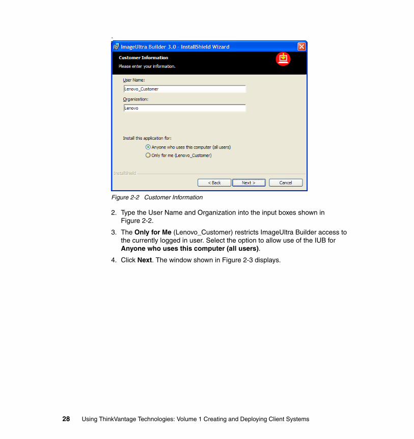
.
Figure 2-2 Customer Information
2. Type the User Name and Organization into the input boxes shown in Figure 2-2.
3. The Only for Me (Lenovo_Customer) restricts ImageUltra Builder access to the currently logged in user. Select the option to allow use of the IUB for Anyone who uses this computer (all users).
4. Click Next. The window shown in Figure 2-3 displays.
28 Using ThinkVantage Technologies: Volume 1 Creating and Deploying Client Systems
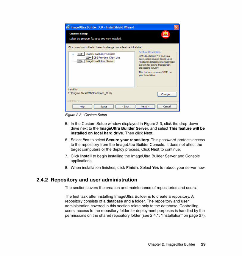
Figure 2-3 Custom Setup
5. In the Custom Setup window displayed in Figure 2-3, click the drop-down drive next to the ImageUltra Builder Server, and select This feature will be installed on local hard drive. Then click Next.
6. Select Yes to select Secure your repository. This password-protects access to the repository from the ImageUltra Builder Console. It does not affect the target computers or the deploy process. Click Next to continue.
7. Click Install to begin installing the ImageUltra Builder Server and Console applications.
8. When installation finishes, click Finish. Select Yes to reboot your server now.
2.4.2 Repository and user administrationThe section covers the creation and maintenance of repositories and users.
The first task after installing ImageUltra Builder is to create a repository. A repository consists of a database and a folder. The repository and user administration covered in this section relate only to the database. Controlling users’ access to the repository folder for deployment purposes is handled by the permissions on the shared repository folder (see 2.4.1, “Installation” on page 27).
Chapter 2. ImageUltra Builder 29
You create repositories from the main ImageUltra Builder interface. You perform all other user and repository administration tasks using the Administration tool accessed from the Tools menu.
Creating a repositoryTo create a repository, open ImageUltra by double-clicking the ImageUltra Builder desktop icon.
Disk space should be a major consideration when deciding where to locate repositories. Each repository requires approximately 250 MB when you create it. Any components, added after repository creation, add to this size.
1. If this is the first time that you open ImageUltra, the Welcome window displays. Click Next. If the Welcome window is not displayed, click File and then click New Repository.
2. After reviewing the Welcome window, click Next. The window shown in Figure 2-4 displays.
Note: A best practice when using ImageUltra Builder is to create the following three repositories:
1. Import
For importing and storing gold modules from Lenovo recovery CDs, service partitions, and modules provided by the Lenovo Image Technology Center (ITC)
2. Test
For testing all new modules and maps
3. Production
For production use, both as a direct deploy and for creating deployment disk sets, described in section 2.11, “Deploy and install with ImageUltra Builder” on page 144
30 Using ThinkVantage Technologies: Volume 1 Creating and Deploying Client Systems
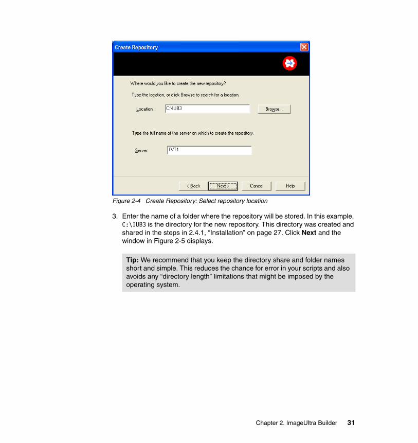
Figure 2-4 Create Repository: Select repository location
3. Enter the name of a folder where the repository will be stored. In this example, C:\IUB3 is the directory for the new repository. This directory was created and shared in the steps in 2.4.1, “Installation” on page 27. Click Next and the window in Figure 2-5 displays.
Tip: We recommend that you keep the directory share and folder names short and simple. This reduces the chance for error in your scripts and also avoids any “directory length” limitations that might be imposed by the operating system.
Chapter 2. ImageUltra Builder 31
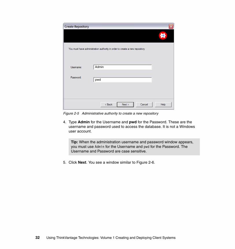
Figure 2-5 Administrative authority to create a new repository
4. Type Admin for the Username and pwd for the Password. These are the username and password used to access the database. It is not a Windows user account.
5. Click Next. You see a window similar to Figure 2-6.
Tip: When the administration username and password window appears, you must use Admin for the Username and pwd for the Password. The Username and Password are case sensitive.
Admin
pwd
32 Using ThinkVantage Technologies: Volume 1 Creating and Deploying Client Systems
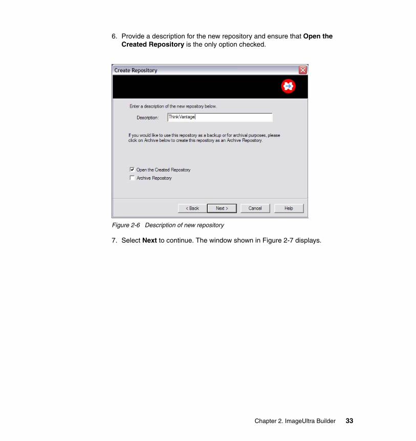
6. Provide a description for the new repository and ensure that Open the Created Repository is the only option checked.
Figure 2-6 Description of new repository
7. Select Next to continue. The window shown in Figure 2-7 displays.
ThinkVantage
Chapter 2. ImageUltra Builder 33
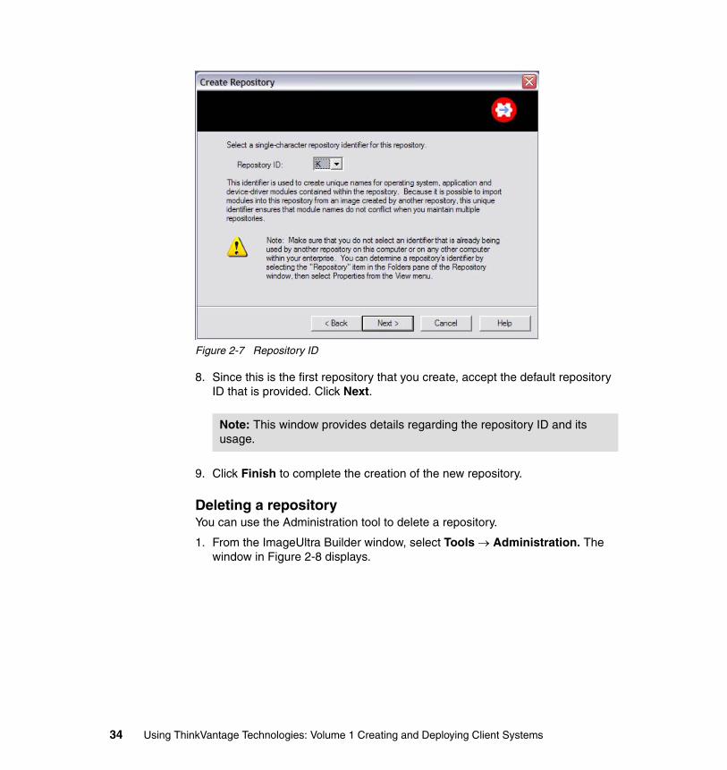
Figure 2-7 Repository ID
8. Since this is the first repository that you create, accept the default repository ID that is provided. Click Next.
9. Click Finish to complete the creation of the new repository.
Deleting a repositoryYou can use the Administration tool to delete a repository.
1. From the ImageUltra Builder window, select Tools → Administration. The window in Figure 2-8 displays.
Note: This window provides details regarding the repository ID and its usage.
34 Using ThinkVantage Technologies: Volume 1 Creating and Deploying Client Systems
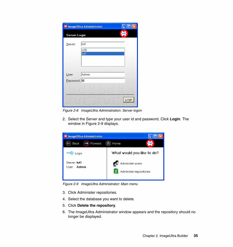
Figure 2-8 ImageUltra Administration: Server logon
2. Select the Server and type your user id and password. Click Login. The window in Figure 2-9 displays.
Figure 2-9 ImageUltra Administrator: Main menu
3. Click Administer repositories.
4. Select the database you want to delete.
5. Click Delete the repository.
6. The ImageUltra Administrator window appears and the repository should no longer be displayed.
Chapter 2. ImageUltra Builder 35
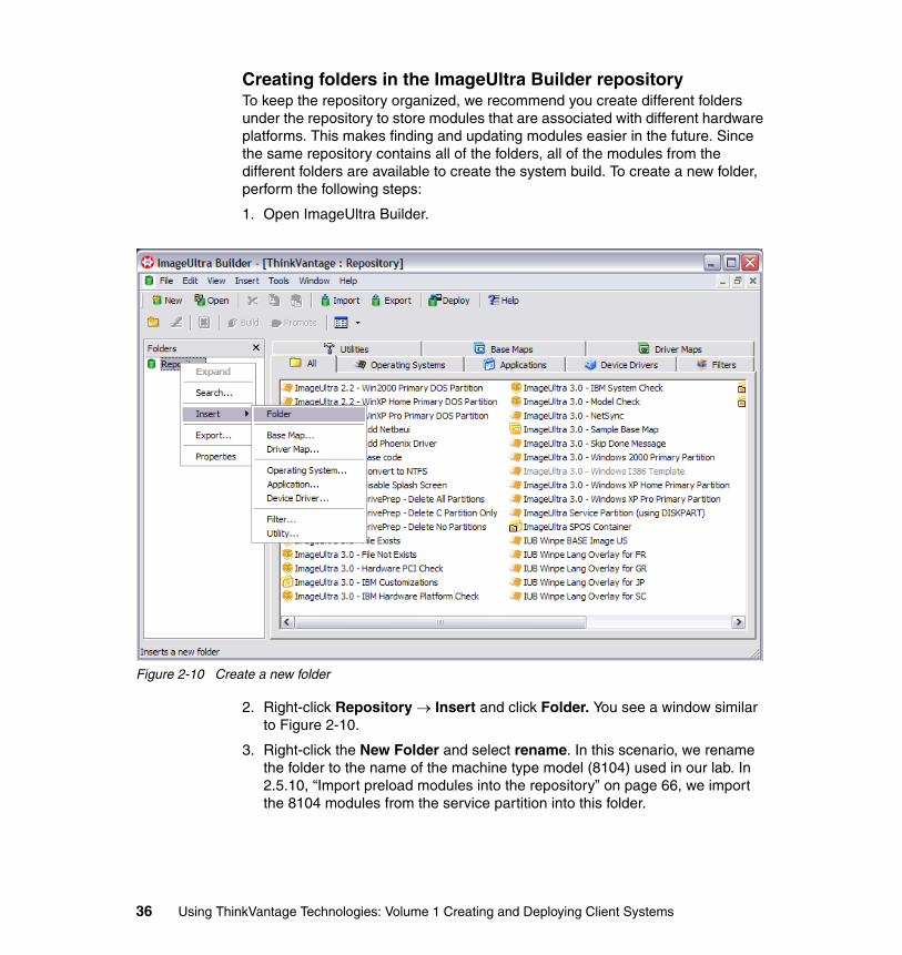
Creating folders in the ImageUltra Builder repositoryTo keep the repository organized, we recommend you create different folders under the repository to store modules that are associated with different hardware platforms. This makes finding and updating modules easier in the future. Since the same repository contains all of the folders, all of the modules from the different folders are available to create the system build. To create a new folder, perform the following steps:
1. Open ImageUltra Builder.
Figure 2-10 Create a new folder
2. Right-click Repository → Insert and click Folder. You see a window similar to Figure 2-10.
3. Right-click the New Folder and select rename. In this scenario, we rename the folder to the name of the machine type model (8104) used in our lab. In 2.5.10, “Import preload modules into the repository” on page 66, we import the 8104 modules from the service partition into this folder.
36 Using ThinkVantage Technologies: Volume 1 Creating and Deploying Client Systems
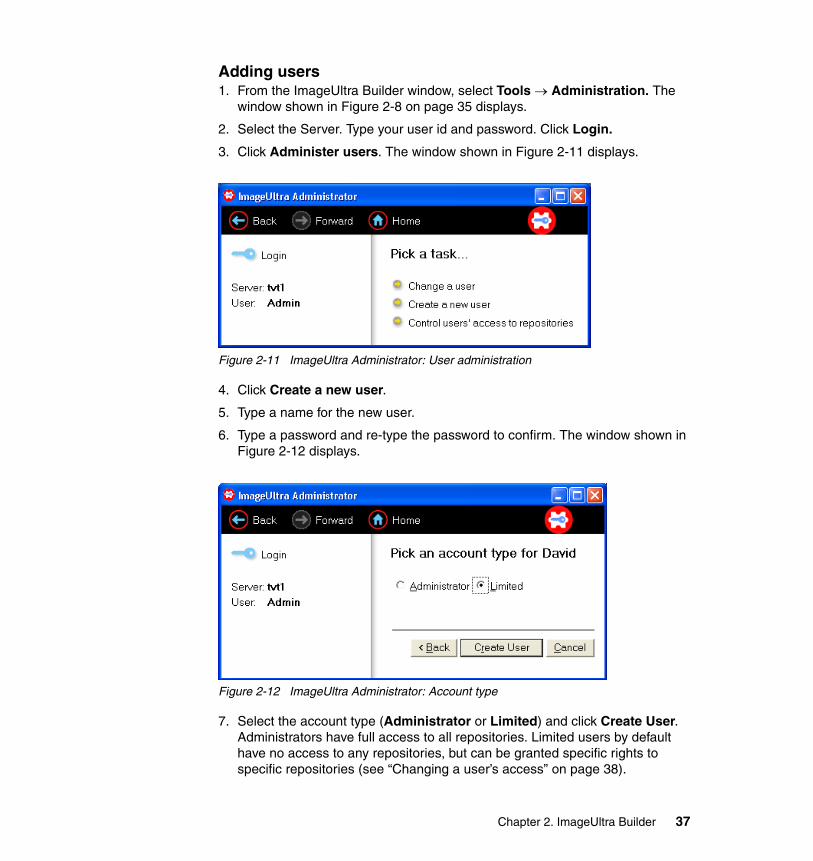
Adding users1. From the ImageUltra Builder window, select Tools → Administration. The
window shown in Figure 2-8 on page 35 displays.
2. Select the Server. Type your user id and password. Click Login.
3. Click Administer users. The window shown in Figure 2-11 displays.
Figure 2-11 ImageUltra Administrator: User administration
4. Click Create a new user.
5. Type a name for the new user.
6. Type a password and re-type the password to confirm. The window shown in Figure 2-12 displays.
Figure 2-12 ImageUltra Administrator: Account type
7. Select the account type (Administrator or Limited) and click Create User. Administrators have full access to all repositories. Limited users by default have no access to any repositories, but can be granted specific rights to specific repositories (see “Changing a user’s access” on page 38).
Chapter 2. ImageUltra Builder 37
The new user can now access the ImageUltra Builder with the credentials created during this process.
Changing a user’s accessThere are two types of users, Limited and Administrators. By default, an Administrator has full access to all repositories, while a Limited user has no access to any repositories. To control a user’s access to certain repositories, they must be a Limited user.
To change a user’s type (Limited or Administrator), perform the following steps:
1. From the ImageUltra Builder window, select Tools → Administration. The window in Figure 2-8 on page 35 displays.
2. Select the Server. Type your user id and password. Click Login.
3. Click Administer users. The window shown in Figure 2-11 on page 37 displays.
4. Click Change a user.
5. Click the user to be changed.
6. Click Change the account type.
7. Select Administrator or Limited and Click Change account type.
To control a Limited user’s access to the repositories, perform the following steps:
1. From the ImageUltra Builder window, select Tools → Administration. The window in Figure 2-8 on page 35 displays.
2. Select the Server. Type your user id and password. Click Login.
3. Click Administer users. The window shown in Figure 2-11 on page 37 displays.
4. Click Control user’s access to repositories. The window shown in Figure 2-13 displays.
38 Using ThinkVantage Technologies: Volume 1 Creating and Deploying Client Systems
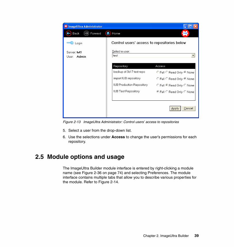
Figure 2-13 ImageUltra Administrator: Control users’ access to repositories
5. Select a user from the drop-down list.
6. Use the selections under Access to change the user’s permissions for each repository.
2.5 Module options and usage
The ImageUltra Builder module interface is entered by right-clicking a module name (see Figure 2-36 on page 74) and selecting Preferences. The module interface contains multiple tabs that allow you to describe various properties for the module. Refer to Figure 2-14.
Chapter 2. ImageUltra Builder 39
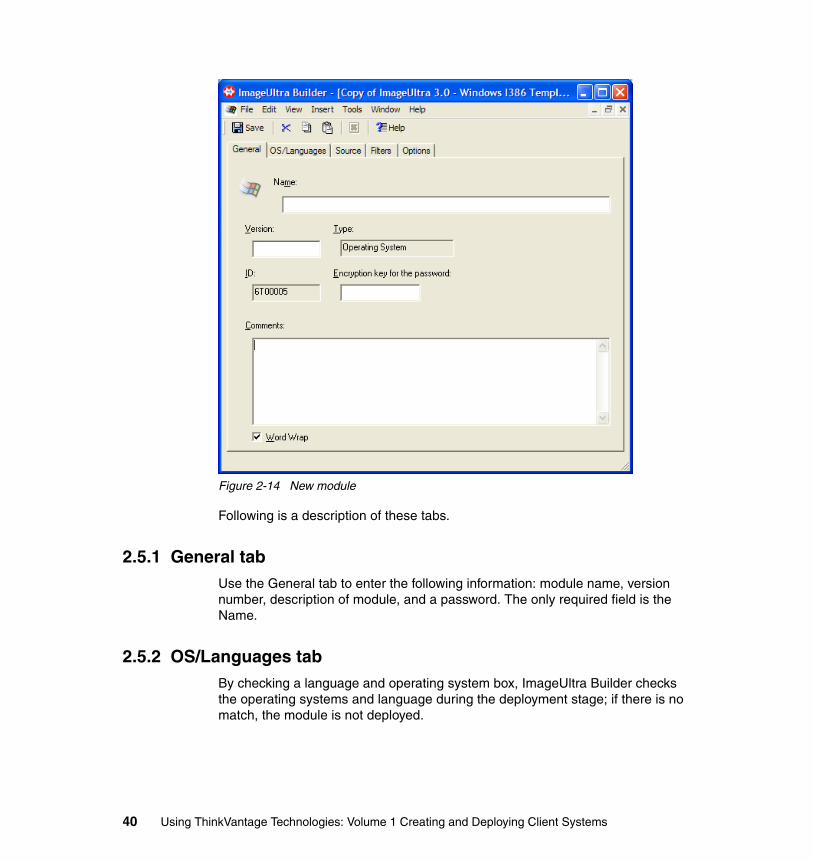
Figure 2-14 New module
Following is a description of these tabs.
2.5.1 General tabUse the General tab to enter the following information: module name, version number, description of module, and a password. The only required field is the Name.
2.5.2 OS/Languages tabBy checking a language and operating system box, ImageUltra Builder checks the operating systems and language during the deployment stage; if there is no match, the module is not deployed.
40 Using ThinkVantage Technologies: Volume 1 Creating and Deploying Client Systems
2.5.3 Source tabIn the Source tab, you detail all commands and files necessary for the execution of a module.
� In the Source directory field, browse to the directory where the source file for this application is located. Example: C:\IUB3\source\apps
� In the Silent install command field, browse to the executable file contained in your source directory. Example: C:\IUB3\source\apps\wrar280.exe
� In the Parameters field, type your silent install switch. Example: /s� Close the Properties window, and when prompted, select Yes to save.
2.5.4 Filters tabFilters are usually Win32 command-line environment-based programs. Typically, they are a .EXE or .BAT file. Once you have created your filter modules, you can then apply them to other modules.
2.5.5 Options tabThere are a number of fields on this tab that allow you to control the installation behavior of the module:
Target locationThese fields define whether the application files should be copied to the target partition.
If you type a path in this field and you also provide a silent install command on the Source tab, the files are copied to the target partition in addition to the application being installed.
If you type a path in this field and you do not provide a silent install command on the Source tab, the files are copied to the target partition, but the application is not installed automatically.
BehaviorThese fields are used to control the module installation order.
� Install hook:
Note: An example of a filter is the ISIMOBLE filter that runs a check to make sure the hardware to which this module is deployed is a ThinkPad.
Chapter 2. ImageUltra Builder 41
– Install during auditboot (Default): This selection enables the module you are creating to be installed during the first boot after the Windows setup is complete.
– Install during customer first boot: This selection enables the module you are creating to be installed after the auditboot, upon successful completion of the Windows setup.
– Install when customer chooses via desktop shortcut: This selection enables users to install the module after the image is installed by clicking a shortcut on the desktop. The ImageUltra Builder program copies the module source files to a folder on the user partition and creates an icon on the desktop that links to the installation file.
� Install slot:
The install slot number determines when a module is installed in relation to other modules that are assigned during the same boot cycle. Install slot numbers range from 1 to 9. The higher the slot number, the later the module is installed.
� Hardware Independent Imaging Technology (HIIT) behavior:
This field determines how Hardware Independent Imaging Technology behavior is implemented during the installation process. This field only applies to modules that you plan to include in a driver map. Typically, you do not want to modify this field unless there are unique circumstances regarding the module you are creating. The following are the choices associated with the HIIT behavior field:
– Normal device detection: This selection is intended for device-driver modules that are used in driver maps.
– Ignore HIIT processing: This selection is intended for unique application modules that are used in driver maps. For example, you may want to include an application that contains application files and device drivers. In this case, you can choose to put the module in both maps.
– Always install: This selection is intended for modules in a driver map that fail to install correctly during normal HIIT processing.
For INF installs only� INF installable: Mark this check box if the module you create is an INF
installable. This field is typically used for device drivers only.
� Relative location of INF files in the source: This field is activated only if the INF installable field is marked. This field requires an entry if INF files needed for this module are not located in the folder defined in the Source directory field of the Source tab. If you need to define a path, the path must be a relative path based on the root folder of the source files.
42 Using ThinkVantage Technologies: Volume 1 Creating and Deploying Client Systems
2.5.6 Modules provided with the builderThis section describe which modules are provided with the default installation of ImageUltra Builder.
When a new repository is created such as the repository described in the section titled 2.4.2, “Repository and user administration” on page 29, the following modules are pre-populated. These gold modules have been created by Lenovo. A brief description of each module is provided below.
� ImageUltra 2.2: Win2000 Primary DOS Partition
– This module installs the WinPE environment that is compatible with Windows 2000 to enable a Windows 2000 IUB solution to be deployed.
� ImageUltra 2.2: WinXP Home Primary DOS Partition
– This module installs the WinPE environment that is compatible with Windows XP Home to enable a Windows XP Home IUB solution to be deployed.
� ImageUltra 2.2: WinXP Pro Primary DOS Partition
– This module installs the WinPE environment that is compatible with Windows XP Professional to enable a Windows XP Professional IUB solution to be deployed.
� ImageUltra 3.0: Add NetBeui
– This module is used to add the NetBeui protocol during an installation for use in a network environment that needs NetBeui protocol.
� ImageUltra 3.0: Add Phoenix Driver
– This module is used to add the Phoenix driver during an ImageUltra deployment.
� ImageUltra 3.0: Base code
– This module is required in all IUB build solutions. It is incorporated automatically as needed by the IUB process.
� ImageUltra 3.0: Convert to NTFS
– This module is used to convert FAT32-formatted partitions to NTFS.– This module’s primary purpose is to provide support for legacy builds
based on FAT32-formatted OS modules.– This module was used in IUB 2.x Portable-Sysprep Image to convert
FAT32-formatted OS deployments to NTFS. The IUB 2.x process was DOS-based, therefore, it could not support NTFS directly. The ImageUltra Builder 3 process is Windows PE-based, so it supports NTFS directly.
Chapter 2. ImageUltra Builder 43
� ImageUltra 3.0: Disable Splash window
– This module is used to disable the splash screen during the ImageUltra deployment.
� ImageUltra 3.0: DrivePrep: Delete All Partitions
– This module is used to delete all visible partitions at the beginning of the ImageUltra Builder process. This module does not remove the service partition or HPA.
� ImageUltra 3.0: DrivePrep: Delete C Partition Only
– This module is used to delete just the active partition on the first hard disk drive. This is used when you have deployed to a multipartition target and you want to preserve data on partitions other than C. One typical use is for re-imaging a system using IU from the service partition where the system had all the user data stored on the D drive.
� ImageUltra 3.0: DrivePrep: Delete No Partitions
– This module is used to preserve one or more preexisting data partitions on a target computer. When this partitioning module is correctly implemented in a map, all partitions on the target computer are preserved, except for the C partition. The new image is then installed in the space previously used by the old C partition.
� ImageUltra 3.0: File Exists
– This is a filtering module used to check a system for a particular file. This can be used to check for a flag file before installing an application.
� ImageUltra 3.0: File Not Exists
– This is a filtering module used to check a system to insure that a particular file does not exist already.
� ImageUltra 3.0: Hardware PCI Check
– This module is used primarily for testing a system for a particular PCI device before installing a driver. This module can also be used to insure that a DVD player is present before installing DVD player software.
� ImageUltra 3.0: IBM Customizations
– This gold module cannot be edited. This module is required for all Ultra-Portable Images. This module enables the ImageUltra Builder process to continue after the OS module has been installed. Without this module, no driver or application modules will be applied to the build. This module provides similar functionality to the IUBCP.exe program that is used for all Portable-Sysprep Images.
44 Using ThinkVantage Technologies: Volume 1 Creating and Deploying Client Systems
� ImageUltra 3.0: IBM Hardware Platform Check
– This module tests the target system’s BIOS to insure that it is a particular MTM or series of MTM. An example is to install Access Connections 3.8 on all 2379-R9Us.
� ImageUltra 3.0: IBM System Check
– This module tests the target system type. This can be used to insure that it is a ThinkPad using the mobile option.
� ImageUltra 3.0: Model Check
– This module tests the target system’s BIOS to insure that it is a particular MTM or series of MTM, for example, installing Access Connections 3.8 on all 2379-R9U.
� ImageUltra 3.0: NetSync
– This module checks the repository for updated maps at the beginning of deployment: If a down-level map is selected, the network-sync function locates the latest map and uses it in place of the down-level map.
� ImageUltra 3.0: Sample Base Map
– This template shows the minimum requirements of a base map to insure proper deployment of a build. The use of this module is described in the section titled “Ultra-Portable Image” on page 123.
� ImageUltra 3.0: Skip Done Message
– This module skips the "Done Message" after an installation completes.
� ImageUltra 3.0: Windows 2000 Primary Partition
– This module prepares the target hard disk to accept a Windows 2000 installation. It creates the partition, formats the partition, and establishes the partition as a bootable partition.
� ImageUltra 3.0: Windows i386™ Template
– This is a module template for Windows XP Professional - English. – When using this i386 module in a Base map, make sure you also include
the IBM Customizations module, a Primary DOS Partition module, and a Windows unattend.txt module.
– If you want to make a Windows 2000 module and/or support another language version of Windows, make sure you check the appropriate Operating System and Language supported on the OS/Languages tab.
– Before building this module, you must type the Source Directory field, which should point to X:\i386 where X: is the CD-ROM drive letter.
– Contains the i386 directory from the OS source CD. This module is required for all Ultra-Portable Images. This particular module does not contain any source code. Each customer must provide a licensed copy of
Chapter 2. ImageUltra Builder 45
the Microsoft Operating System. The i386 directory is copied into this module.
� ImageUltra 3.0: Windows XP Home Primary Partition
– This module prepares the target hard disk to accept a Windows XP Home installation. It creates the partition, formats the partition, and establishes the partition as a bootable partition.
� ImageUltra 3.0: Windows XP Pro Primary Partition
– This module prepares the target hard disk to accept a Windows XP Pro installation. It creates the partition, formats the partition, and establishes the partition as a bootable partition.
� ImageUltra Service Partition (using DISKPART)
– This module creates the Service Partition for storing the modules and maps during installation and deployment.
� ImageUltra SPOS Container
– A container module that holds all of the modules required for the Service Partition's Operating System (SPOS).
� IUB Winpe BASE Image US
– Windows PE OS base module.
� IUB Winpe Lang Overlay for FR
– Windows PE language pack for French.
� IUB Winpe Lang Overlay for GR
– Windows PE language pack for German.
� IUB Winpe Lang Overlay for JP
– Windows PE language pack for Japanese.
� IUB Winpe Lang Overlay for SC
– Windows PE language pack for Simplified Chinese.
� NetSync Container
– A container module that holds all of the modules required for the NetSync feature.
� SP Container
– A container module that holds all of the modules required for the default Service Partition.
46 Using ThinkVantage Technologies: Volume 1 Creating and Deploying Client Systems
2.5.7 Creating custom modulesAny application, device driver, or add-on operating-system component that you intend to deploy as a module must be prepared to perform an unattended/silent installation. This is mandatory for all application and device driver packages that you want to install as part of an ImageUltra Builder Smart Image.
The method used to prepare an application for “silent installation” varies depending on the installation mechanism being used.
Common tools we use to generate silent install packages for your applications or device drivers are Windows Installer and InstallShield. We discuss both in the following sections.
Windows InstallerMsiexec.exe is the Windows Installer executable that runs the Windows Installer service. The Windows Installer service installs and manages installation packages written to specific standards and stored as a database in files with the .MSI extension.
The Windows Installer reads the installation database, performs the installation, and then monitors the installed software to ensure functionality. When an .MSI is opened, msiexec.exe reads the data stored in the database and builds an internal script. It then performs the actions in the script to complete the installation. Sometimes Install Packages pre-install Windows Installer as part of their installation package.
A transform is a special kind of Windows Installer file (.MST file) that customizes a Windows Installer installation package. You use it to change the installation in some way for a specific set of customers or users.
The Windows Installer service does allow an installation package to be installed silently.
You can use one of four User Interface Levels while installing a package:
� NONE (completely silent installation)
� BASIC (simple progress bar and error handling)
Note:
� An unattended installation is one which does not require any user interaction.
� A silent installation is one which does not display any indication of its progress.
Chapter 2. ImageUltra Builder 47
� REDUCED (authorized UI, wizard dialogs suppressed)
� FULL (authorized UI with wizards, progress bar, errors)
To run an installation package silently, you need to use the following command:
MSIEXEC /i Product.msi /qn
If your release settings include SETUP.EXE, you can run the following command:
SETUP.EXE /s /v"/qn"
Basic MSI projects do not create or read response files. To set installation properties for a Basic MSI project, use a command similar to the following:
MSIEXEC /i Product.msi /qn INSTALLDIR=D:\ProductFolder USERNAME="Valued Customer"
See the documentation associated with the specific installation product if you encounter any problems.
InstallShieldInstallShield is a very commonly used application packaging system. Installation packages created using InstallShield recognize commands such as /s, /SMS /r, and so on. The installer itself is the setup.exe file. To ensure the application installs silently, you need to generate a response file (.iss file) if one is not already present. Both of these files, plus any other files necessary to install your package, need to be stored in the same folder. See Figure 2-15.
48 Using ThinkVantage Technologies: Volume 1 Creating and Deploying Client Systems
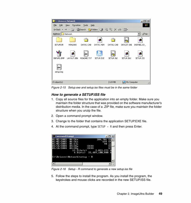
Figure 2-15 Setup.exe and setup.iss files must be in the same folder
How to generate a SETUP.ISS file1. Copy all source files for the application into an empty folder. Make sure you
maintain the folder structure that was provided on the software manufacturer’s distribution media. In the case of a .ZIP file, make sure you maintain the folder structure when you unzip the file.
2. Open a command prompt window.
3. Change to the folder that contains the application SETUP.EXE file.
4. At the command prompt, type SETUP - R and then press Enter.
Figure 2-16 Setup - R command to generate a new setup.iss file
5. Follow the steps to install the program. As you install the program, the keystrokes and mouse clicks are recorded in the new SETUP.ISS file.
Chapter 2. ImageUltra Builder 49
Because the values you type will be used on all target computers, when prompted, respond with company-related information instead of personal information.
6. When the installation is complete, the new SETUP.ISS file is in the Windows folder for Windows XP and the WINNT folder for Windows 2000.
7. Copy the new SETUP.ISS file from the Windows folder into the folder that contains the application SETUP.EXE file.
Now that you have generated all necessary files to silently install your package, you can create a module in ImageUltra Builder from these source files.
2.5.8 Creating an application module from source filesFor this example, we create an application module based on the application WinRAR. These are the steps to create an application module from your application source files:
1. Open your ImageUltra Builder repository and select the location where you want to create your new application module.
2. Select the Applications tab.
3. Right-click the space in the window, select Insert application.
4. Click Next.
5. You see a window similar to Figure 2-17.
Note: Newer versions of InstallShield may involve different steps.
50 Using ThinkVantage Technologies: Volume 1 Creating and Deploying Client Systems
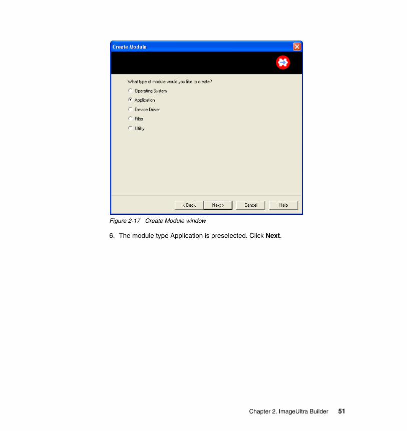
Figure 2-17 Create Module window
6. The module type Application is preselected. Click Next.
Chapter 2. ImageUltra Builder 51
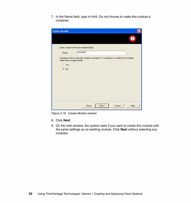
7. In the Name field, type WinRAR. Do not choose to make this module a container.
Figure 2-18 Create Module window
8. Click Next.
9. On the next window, the system asks if you want to create this module with the same settings as an existing module. Click Next without selecting any modules.
52 Using ThinkVantage Technologies: Volume 1 Creating and Deploying Client Systems
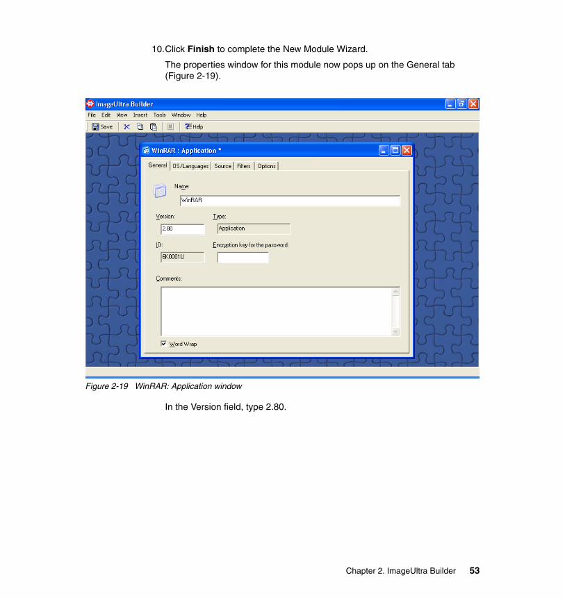
10.Click Finish to complete the New Module Wizard.
The properties window for this module now pops up on the General tab (Figure 2-19).
Figure 2-19 WinRAR: Application window
In the Version field, type 2.80.
Chapter 2. ImageUltra Builder 53
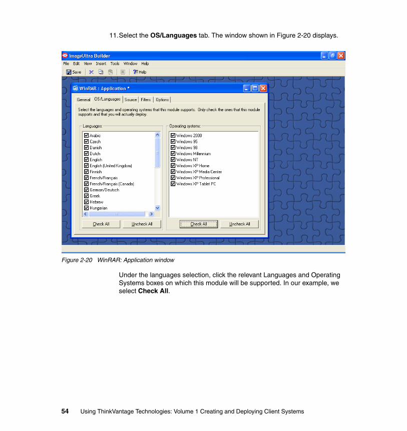
11.Select the OS/Languages tab. The window shown in Figure 2-20 displays.
Figure 2-20 WinRAR: Application window
Under the languages selection, click the relevant Languages and Operating Systems boxes on which this module will be supported. In our example, we select Check All.
54 Using ThinkVantage Technologies: Volume 1 Creating and Deploying Client Systems
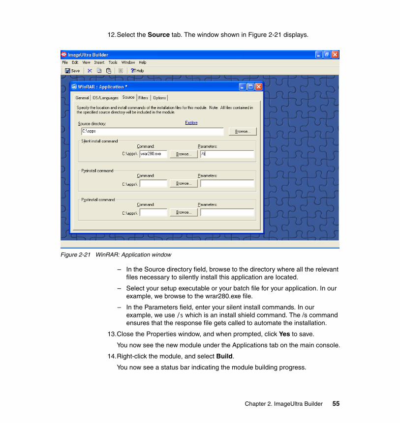
12.Select the Source tab. The window shown in Figure 2-21 displays.
Figure 2-21 WinRAR: Application window
– In the Source directory field, browse to the directory where all the relevant files necessary to silently install this application are located.
– Select your setup executable or your batch file for your application. In our example, we browse to the wrar280.exe file.
– In the Parameters field, enter your silent install commands. In our example, we use /s which is an install shield command. The /s command ensures that the response file gets called to automate the installation.
13.Close the Properties window, and when prompted, click Yes to save.
You now see the new module under the Applications tab on the main console.
14.Right-click the module, and select Build.
You now see a status bar indicating the module building progress.
Chapter 2. ImageUltra Builder 55
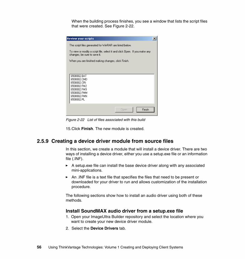
When the building process finishes, you see a window that lists the script files that were created. See Figure 2-22.
Figure 2-22 List of files associated with this build
15.Click Finish. The new module is created.
2.5.9 Creating a device driver module from source filesIn this section, we create a module that will install a device driver. There are two ways of installing a device driver, either you use a setup.exe file or an information file (.INF).
� A setup.exe file can install the base device driver along with any associated mini-applications.
� An .INF file is a text file that specifies the files that need to be present or downloaded for your driver to run and allows customization of the installation procedure.
The following sections show how to install an audio driver using both of these methods.
Install SoundMAX audio driver from a setup.exe file1. Open your ImageUltra Builder repository and select the location where you
want to create your new device driver module.
2. Select the Device Drivers tab.
56 Using ThinkVantage Technologies: Volume 1 Creating and Deploying Client Systems
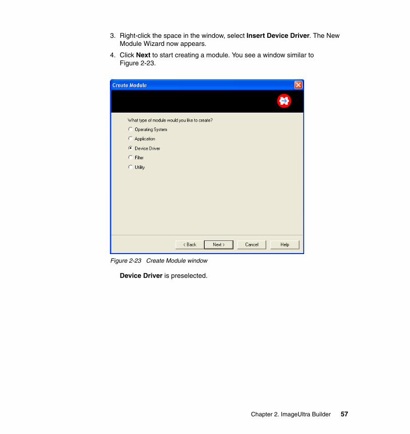
3. Right-click the space in the window, select Insert Device Driver. The New Module Wizard now appears.
4. Click Next to start creating a module. You see a window similar to Figure 2-23.
Figure 2-23 Create Module window
Device Driver is preselected.
Chapter 2. ImageUltra Builder 57
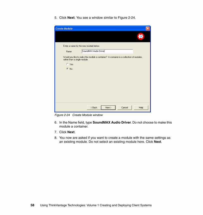
5. Click Next. You see a window similar to Figure 2-24.
Figure 2-24 Create Module window
6. In the Name field, type SoundMAX Audio Driver. Do not choose to make this module a container.
7. Click Next.
8. You now are asked if you want to create a module with the same settings as an existing module. Do not select an existing module here. Click Next.
58 Using ThinkVantage Technologies: Volume 1 Creating and Deploying Client Systems
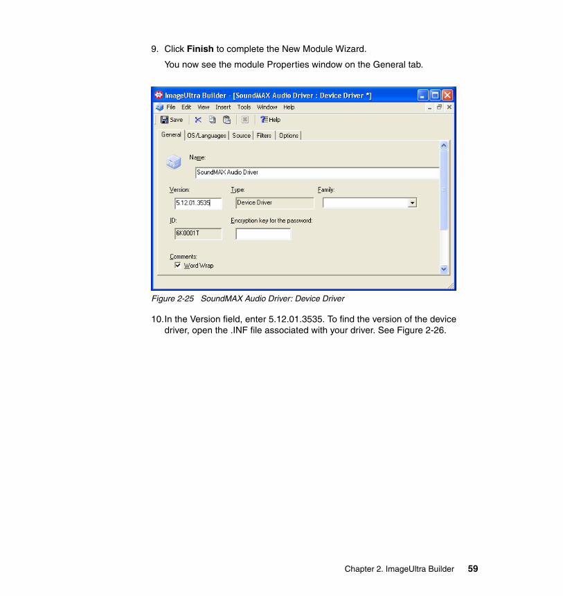
9. Click Finish to complete the New Module Wizard.
You now see the module Properties window on the General tab.
Figure 2-25 SoundMAX Audio Driver: Device Driver
10.In the Version field, enter 5.12.01.3535. To find the version of the device driver, open the .INF file associated with your driver. See Figure 2-26.
Chapter 2. ImageUltra Builder 59
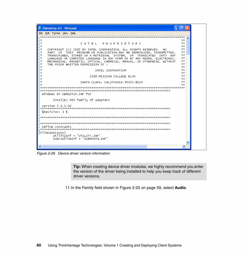
Figure 2-26 Device driver version information
11.In the Family field shown in Figure 2-25 on page 59, select Audio.
Tip: When creating device driver modules, we highly recommend you enter the version of the driver being installed to help you keep track of different driver versions.
60 Using ThinkVantage Technologies: Volume 1 Creating and Deploying Client Systems
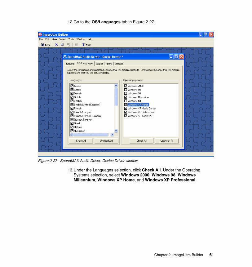
12.Go to the OS/Languages tab in Figure 2-27.
Figure 2-27 SoundMAX Audio Driver: Device Driver window
13.Under the Languages selection, click Check All. Under the Operating Systems selection, select Windows 2000, Windows 98, Windows Millennium, Windows XP Home, and Windows XP Professional.
Chapter 2. ImageUltra Builder 61
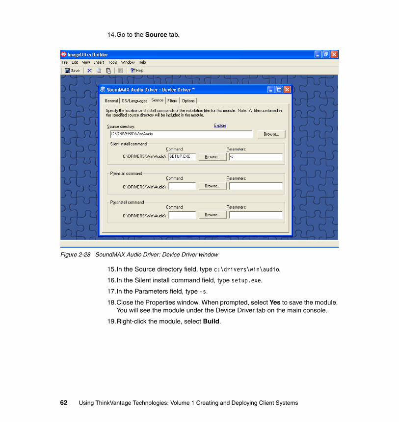
14.Go to the Source tab.
Figure 2-28 SoundMAX Audio Driver: Device Driver window
15.In the Source directory field, type c:\drivers\win\audio.
16.In the Silent install command field, type setup.exe.
17.In the Parameters field, type -s.
18.Close the Properties window. When prompted, select Yes to save the module. You will see the module under the Device Driver tab on the main console.
19.Right-click the module, select Build.
62 Using ThinkVantage Technologies: Volume 1 Creating and Deploying Client Systems
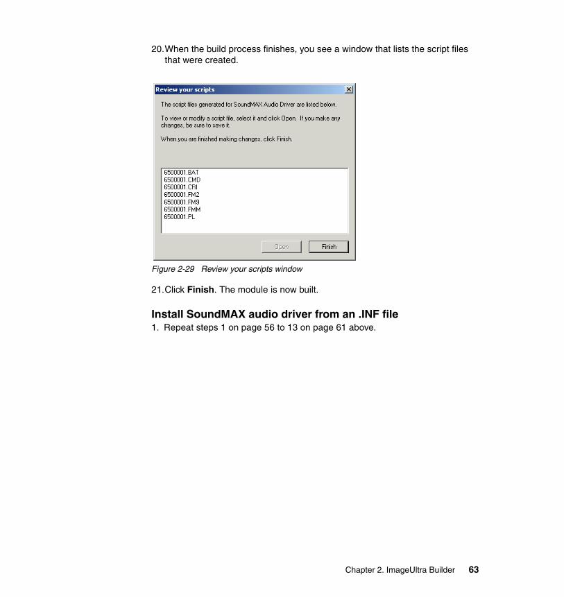
20.When the build process finishes, you see a window that lists the script files that were created.
Figure 2-29 Review your scripts window
21.Click Finish. The module is now built.
Install SoundMAX audio driver from an .INF file1. Repeat steps 1 on page 56 to 13 on page 61 above.
Chapter 2. ImageUltra Builder 63
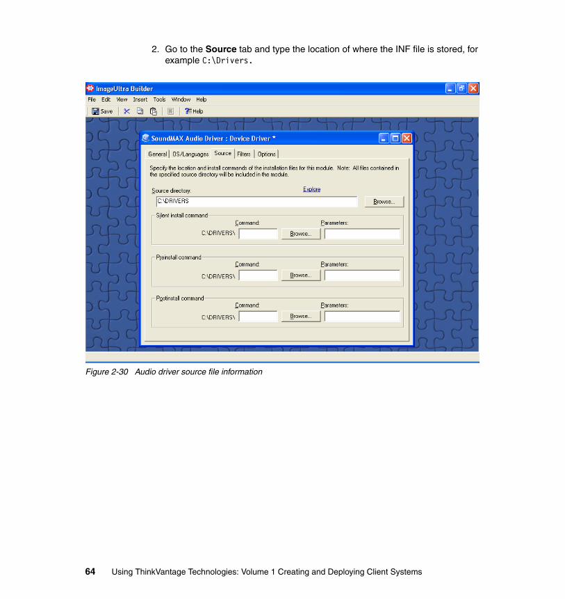
2. Go to the Source tab and type the location of where the INF file is stored, for example C:\Drivers.
Figure 2-30 Audio driver source file information
64 Using ThinkVantage Technologies: Volume 1 Creating and Deploying Client Systems
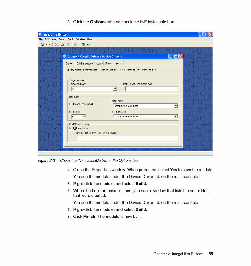
3. Click the Options tab and check the INF installable box.
Figure 2-31 Check the INF installable box in the Options tab
4. Close the Properties window. When prompted, select Yes to save the module.
You see the module under the Device Driver tab on the main console.
5. Right-click the module, and select Build.
6. When the build process finishes, you see a window that lists the script files that were created.
You see the module under the Device Driver tab on the main console.
7. Right-click the module, and select Build.
8. Click Finish. The module is now built.
Chapter 2. ImageUltra Builder 65
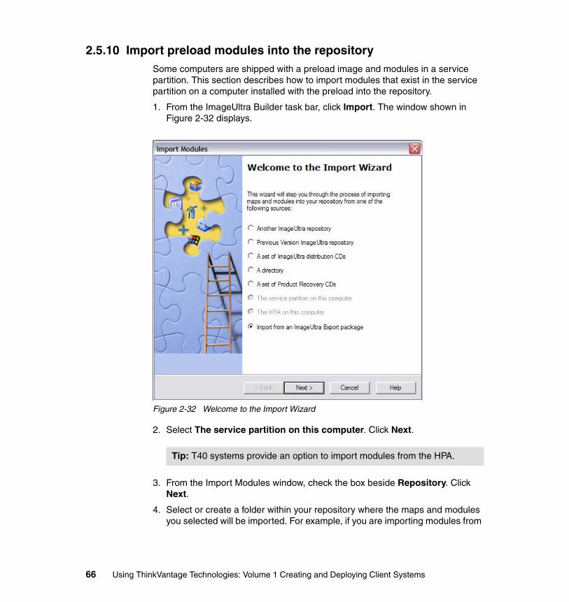
2.5.10 Import preload modules into the repositorySome computers are shipped with a preload image and modules in a service partition. This section describes how to import modules that exist in the service partition on a computer installed with the preload into the repository.
1. From the ImageUltra Builder task bar, click Import. The window shown in Figure 2-32 displays.
Figure 2-32 Welcome to the Import Wizard
2. Select The service partition on this computer. Click Next.
3. From the Import Modules window, check the box beside Repository. Click Next.
4. Select or create a folder within your repository where the maps and modules you selected will be imported. For example, if you are importing modules from
Tip: T40 systems provide an option to import modules from the HPA.
66 Using ThinkVantage Technologies: Volume 1 Creating and Deploying Client Systems
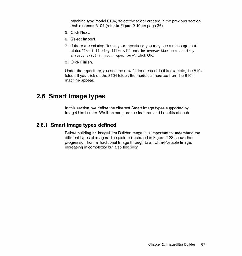
machine type model 8104, select the folder created in the previous section that is named 8104 (refer to Figure 2-10 on page 36).
5. Click Next.
6. Select Import.
7. If there are existing files in your repository, you may see a message that states “The following files will not be overwritten because they already exist in your repository”. Click OK.
8. Click Finish.
Under the repository, you see the new folder created, in this example, the 8104 folder. If you click on the 8104 folder, the modules imported from the 8104 machine appear.
2.6 Smart Image types
In this section, we define the different Smart Image types supported by ImageUltra builder. We then compare the features and benefits of each.
2.6.1 Smart Image types definedBefore building an ImageUltra Builder image, it is important to understand the different types of images. The picture illustrated in Figure 2-33 shows the progression from a Traditional Image through to an Ultra-Portable Image, increasing in complexity but also flexibility.
Chapter 2. ImageUltra Builder 67
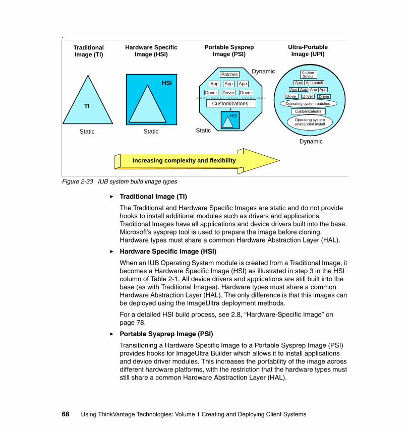
.
Figure 2-33 IUB system build image types
� Traditional Image (TI)
The Traditional and Hardware Specific Images are static and do not provide hooks to install additional modules such as drivers and applications. Traditional Images have all applications and device drivers built into the base. Microsoft’s sysprep tool is used to prepare the image before cloning. Hardware types must share a common Hardware Abstraction Layer (HAL).
� Hardware Specific Image (HSI)
When an IUB Operating System module is created from a Traditional Image, it becomes a Hardware Specific Image (HSI) as illustrated in step 3 in the HSI column of Table 2-1. All device drivers and applications are still built into the base (as with Traditional Images). Hardware types must share a common Hardware Abstraction Layer (HAL). The only difference is that this images can be deployed using the ImageUltra deployment methods.
For a detailed HSI build process, see 2.8, “Hardware-Specific Image” on page 78.
� Portable Sysprep Image (PSI)
Transitioning a Hardware Specific Image to a Portable Sysprep Image (PSI) provides hooks for ImageUltra Builder which allows it to install applications and device driver modules. This increases the portability of the image across different hardware platforms, with the restriction that the hardware types must still share a common Hardware Abstraction Layer (HAL).
TraditionalImage (TI)
Hardware SpecificImage (HSI)
Portable SysprepImage (PSI)
Ultra-PortableImage (UPI)
Increasing complexity and flexibility
TIHSI
Static Static Static
Dynamic
+
Driver Driver Driver
App AppApp
Patches CustomScripts
App patchApp
App App App App
Driver Driver Driver
Operating system patches
Customizations
Operating systemunattended install
Customizations
HSI
Dynamic
68 Using ThinkVantage Technologies: Volume 1 Creating and Deploying Client Systems

The hooks are provided by running the IUB Customization Program (IUBCP) before the client (donor) system image is captured (see step 1 in the PSI column of Table 2-1).
For details on the limitations of sysprep and an explanation of the Hardware Abstraction Layer, refer to section A.1, “Sysprep hardware limitations and HALs” on page 374.
For a detailed PSI build process, see 2.9, “Portable-Sysprep Image” on page 99.
A comparison of the steps required to create TI, HSI, and PSI image types is shown in Table 2-1. Steps required to create an Ultra-Portable Image (PSI) are listed in Table 2-2 on page 70.
Table 2-1 IUB system build image comparison
� Ultra-Portable Image (UPI)
In contrast to the previously mentioned image types, the Ultra-Portable Image (UPI) is the most complex, but provides the most flexibility. The UPI is the basis for a complex smart image that can be deployed over any Intel® based computer within an organization. However, the trade-off is that the time required to install the image is longer than for all the other image types.
The Ultra-Portable Image has two significant advantages:
Traditional Image (TI) Hardware Specific Image (HSI) Portable Sysprep Image (PSI)
1.) Build machine– Sysprep
1.) Build machine– Sysprep
1.) Build machine– IUBCP– Sysprep
2.) Capture Ghost image 2.) Capture Ghost image 2.) Capture Ghost image
3.) Create IUB OS module of Ghost image
– Add to base map
3.) Create IUB OS module of Ghost image
– Add to base map
4.) Create partitioning modules– Add to base map
4.) Create partitioning modules– Add to base map
Note: Chipset, drivers, and HAL are fixed to what is included in the Ghost image.
5.) Create driver and application modules
– Add drivers to driver map– Add apps to base map
Note: Post Install - allows you to add apps and drivers not included in the Ghost image. Still restricted to HAL.
Chapter 2. ImageUltra Builder 69
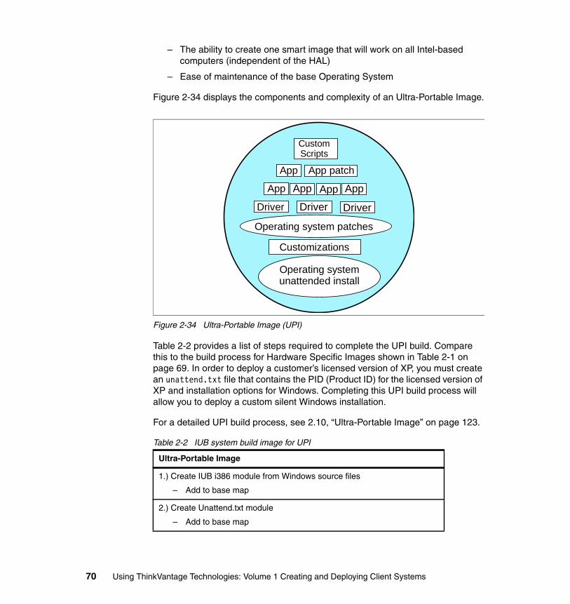
– The ability to create one smart image that will work on all Intel-based computers (independent of the HAL)
– Ease of maintenance of the base Operating System
Figure 2-34 displays the components and complexity of an Ultra-Portable Image.
Figure 2-34 Ultra-Portable Image (UPI)
Table 2-2 provides a list of steps required to complete the UPI build. Compare this to the build process for Hardware Specific Images shown in Table 2-1 on page 69. In order to deploy a customer’s licensed version of XP, you must create an unattend.txt file that contains the PID (Product ID) for the licensed version of XP and installation options for Windows. Completing this UPI build process will allow you to deploy a custom silent Windows installation.
For a detailed UPI build process, see 2.10, “Ultra-Portable Image” on page 123.
Table 2-2 IUB system build image for UPI
Ultra-Portable Image
1.) Create IUB i386 module from Windows source files
– Add to base map
2.) Create Unattend.txt module
– Add to base map
CustomScripts
App patchApp
App App App App
Driver Driver Driver
Operating system patches
Customizations
Operating systemunattended install
70 Using ThinkVantage Technologies: Volume 1 Creating and Deploying Client Systems
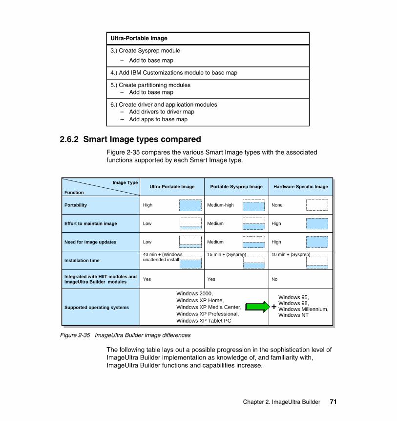
2.6.2 Smart Image types comparedFigure 2-35 compares the various Smart Image types with the associated functions supported by each Smart Image type.
Figure 2-35 ImageUltra Builder image differences
The following table lays out a possible progression in the sophistication level of ImageUltra Builder implementation as knowledge of, and familiarity with, ImageUltra Builder functions and capabilities increase.
3.) Create Sysprep module
– Add to base map
4.) Add IBM Customizations module to base map
5.) Create partitioning modules– Add to base map
6.) Create driver and application modules– Add drivers to driver map– Add apps to base map
Ultra-Portable Image
FunctionUltra-Portable Image Portable-Sysprep Image Hardware Specific Image
Portability High Medium-high None
Effort to maintain image Low Medium High
Need for image updates Low Medium High
Installation time40 min + (Windows unattended install
15 min + (Sysprep) 10 min + (Sysprep)
Integrated with HIIT modules and ImageUltra Builder modules Yes Yes No
Supported operating systems
Image Type
Windows 2000,Windows XP Home,Windows XP Media Center,Windows XP Professional,Windows XP Tablet PC
Windows 95, Windows 98, Windows Millennium, Windows NT
+
Chapter 2. ImageUltra Builder 71
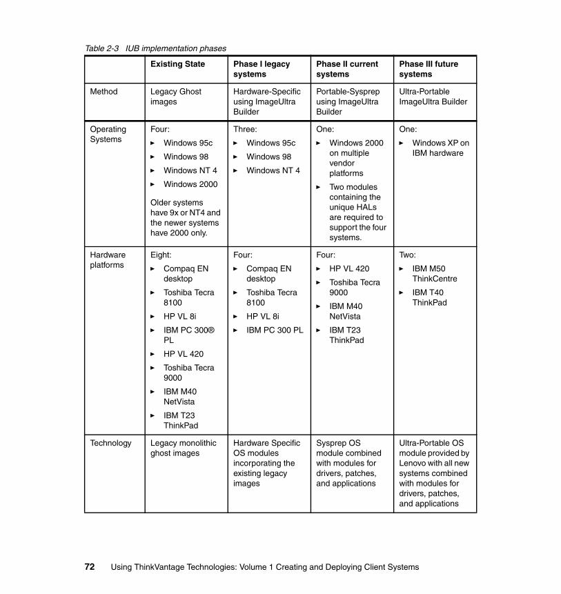
Table 2-3 IUB implementation phases
Existing State Phase I legacy systems
Phase II current systems
Phase III future systems
Method Legacy Ghost images
Hardware-Specific using ImageUltra Builder
Portable-Sysprep using ImageUltra Builder
Ultra-Portable ImageUltra Builder
Operating Systems
Four:
� Windows 95c
� Windows 98
� Windows NT 4
� Windows 2000
Older systems have 9x or NT4 and the newer systems have 2000 only.
Three:
� Windows 95c
� Windows 98
� Windows NT 4
One:
� Windows 2000 on multiple vendor platforms
� Two modules containing the unique HALs are required to support the four systems.
One:
� Windows XP on IBM hardware
Hardware platforms
Eight:
� Compaq EN desktop
� Toshiba Tecra 8100
� HP VL 8i
� IBM PC 300® PL
� HP VL 420
� Toshiba Tecra 9000
� IBM M40 NetVista
� IBM T23 ThinkPad
Four:
� Compaq EN desktop
� Toshiba Tecra 8100
� HP VL 8i
� IBM PC 300 PL
Four:
� HP VL 420
� Toshiba Tecra 9000
� IBM M40 NetVista
� IBM T23 ThinkPad
Two:
� IBM M50 ThinkCentre
� IBM T40 ThinkPad
Technology Legacy monolithic ghost images
Hardware Specific OS modules incorporating the existing legacy images
Sysprep OS module combined with modules for drivers, patches, and applications
Ultra-Portable OS module provided by Lenovo with all new systems combined with modules for drivers, patches, and applications
72 Using ThinkVantage Technologies: Volume 1 Creating and Deploying Client Systems
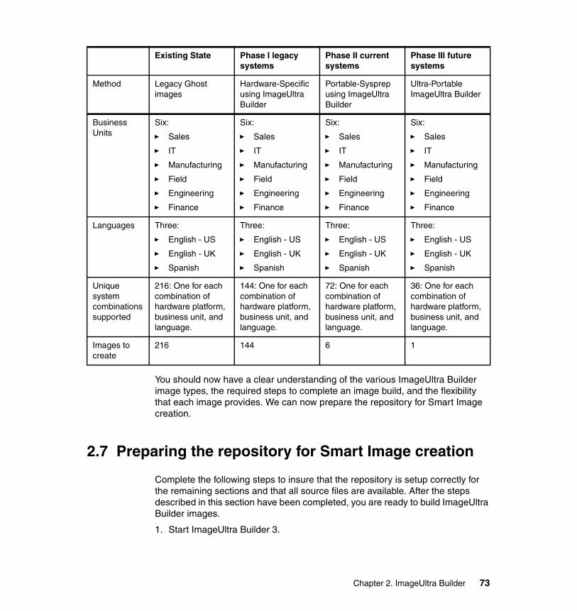
You should now have a clear understanding of the various ImageUltra Builder image types, the required steps to complete an image build, and the flexibility that each image provides. We can now prepare the repository for Smart Image creation.
2.7 Preparing the repository for Smart Image creation
Complete the following steps to insure that the repository is setup correctly for the remaining sections and that all source files are available. After the steps described in this section have been completed, you are ready to build ImageUltra Builder images.
1. Start ImageUltra Builder 3.
Business Units
Six:
� Sales
� IT
� Manufacturing
� Field
� Engineering
� Finance
Six:
� Sales
� IT
� Manufacturing
� Field
� Engineering
� Finance
Six:
� Sales
� IT
� Manufacturing
� Field
� Engineering
� Finance
Six:
� Sales
� IT
� Manufacturing
� Field
� Engineering
� Finance
Languages Three:
� English - US
� English - UK
� Spanish
Three:
� English - US
� English - UK
� Spanish
Three:
� English - US
� English - UK
� Spanish
Three:
� English - US
� English - UK
� Spanish
Unique system combinations supported
216: One for each combination of hardware platform, business unit, and language.
144: One for each combination of hardware platform, business unit, and language.
72: One for each combination of hardware platform, business unit, and language.
36: One for each combination of hardware platform, business unit, and language.
Images to create
216 144 6 1
Existing State Phase I legacy systems
Phase II current systems
Phase III future systems
Method Legacy Ghost images
Hardware-Specific using ImageUltra Builder
Portable-Sysprep using ImageUltra Builder
Ultra-Portable ImageUltra Builder
Chapter 2. ImageUltra Builder 73
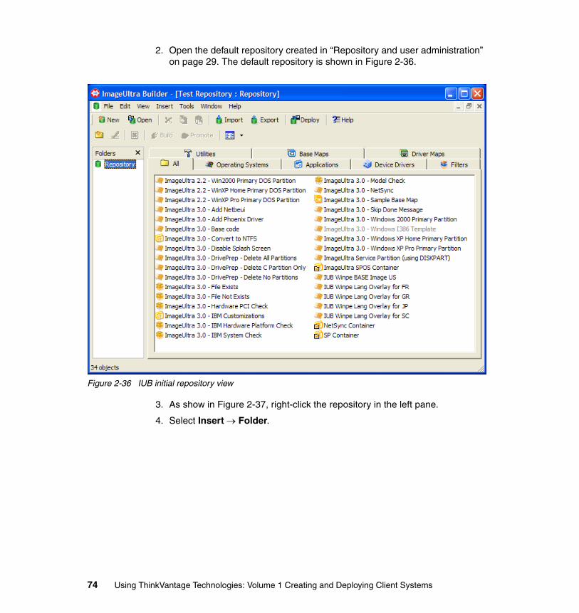
2. Open the default repository created in “Repository and user administration” on page 29. The default repository is shown in Figure 2-36.
Figure 2-36 IUB initial repository view
3. As show in Figure 2-37, right-click the repository in the left pane.
4. Select Insert → Folder.
74 Using ThinkVantage Technologies: Volume 1 Creating and Deploying Client Systems
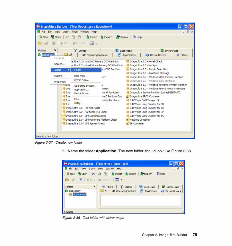
Figure 2-37 Create new folder
5. Name the folder Application. The new folder should look like Figure 2-38.
Figure 2-38 Test folder with driver maps
Chapter 2. ImageUltra Builder 75
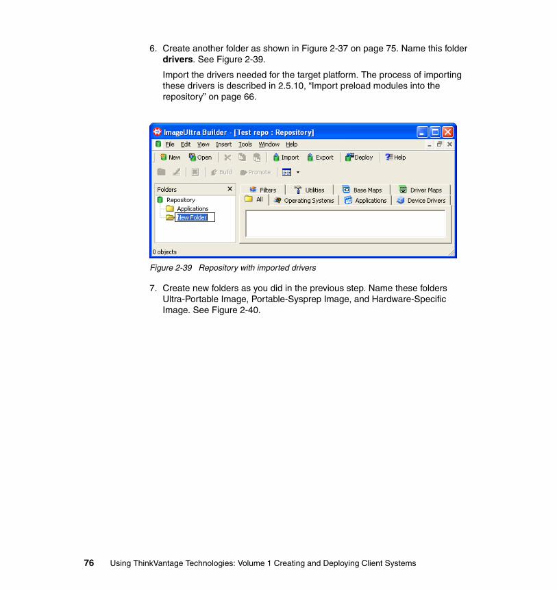
6. Create another folder as shown in Figure 2-37 on page 75. Name this folder drivers. See Figure 2-39.
Import the drivers needed for the target platform. The process of importing these drivers is described in 2.5.10, “Import preload modules into the repository” on page 66.
Figure 2-39 Repository with imported drivers
7. Create new folders as you did in the previous step. Name these folders Ultra-Portable Image, Portable-Sysprep Image, and Hardware-Specific Image. See Figure 2-40.
76 Using ThinkVantage Technologies: Volume 1 Creating and Deploying Client Systems
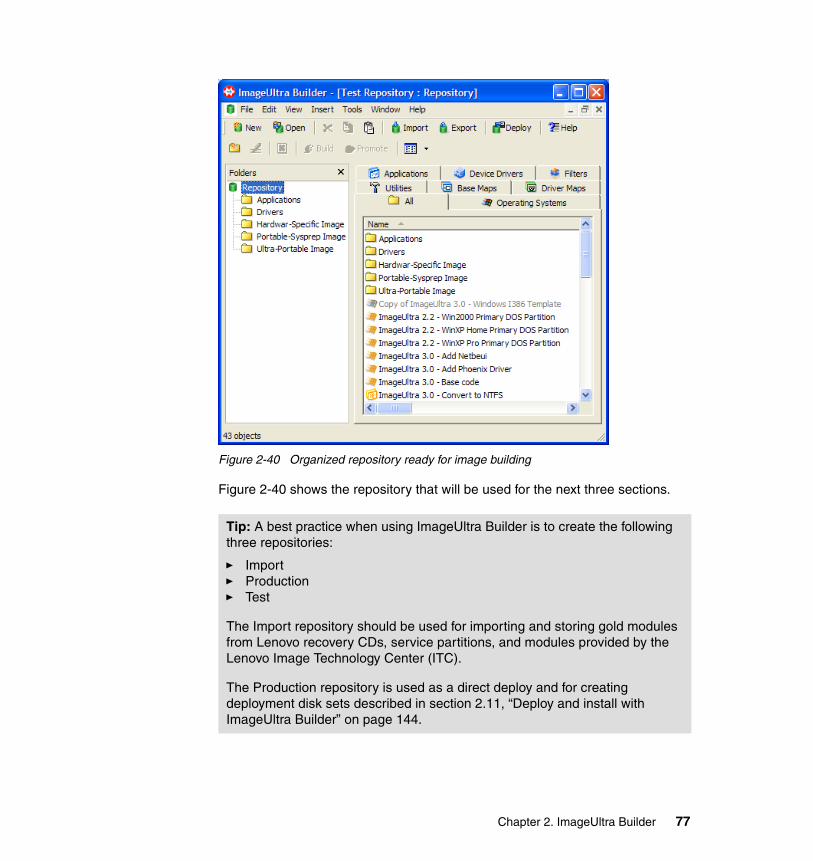
Figure 2-40 Organized repository ready for image building
Figure 2-40 shows the repository that will be used for the next three sections.
Tip: A best practice when using ImageUltra Builder is to create the following three repositories:
� Import� Production� Test
The Import repository should be used for importing and storing gold modules from Lenovo recovery CDs, service partitions, and modules provided by the Lenovo Image Technology Center (ITC).
The Production repository is used as a direct deploy and for creating deployment disk sets described in section 2.11, “Deploy and install with ImageUltra Builder” on page 144.
Chapter 2. ImageUltra Builder 77
In the following sections, the creation of a “Hardware-Specific Image” on page 78, “Portable-Sysprep Image” on page 99, and the “Ultra-Portable Image” on page 123 are described in detail. It is assumed that the reader understands all terms and concepts presented so far in this chapter. The repository shown in Figure 2-40 will be used as the starting point in each of these sections.
2.8 Hardware-Specific Image
The Hardware-Specific Image (HSI) is a Traditional Image (TI) wrapped into an ImageUltra Builder module. This enables IUB to deploy a Traditional Image. Typical use of the HSI is during transition from traditional imaging to the ImageUltra Builder solution. The other use of the HSI is for legacy systems that will not be actively updated. This enables a single system deployment interface for technicians with a mix of Hardware-Specific Images, Portable-Sysprep Images and Ultra-Portable Images.
2.8.1 Creating a seed system for use in Hardware-Specific ImageComplete the following steps to prepare a seed system before the image is taken.
1. Install a supported operating system on the seed system. The following is a list of operating systems supported by the HSI solution.
Supported operating systems
– Windows 95– Windows 98
Note: A thorough knowledge of the Microsoft sysprep tool is assumed. Portable-Sysprep Images and Hardware-Specific Images are based on images created from a source computer that has gone through a Windows setup operation. Specific user and hardware information must be removed from the source computer using the sysprep tool before the image can be deployed to other computers.
Note: System names used in this section:
� A seed or donor system is a system used to develop and customize an operating system for use as a base OS module in the Portable-Sysprep Image process.
� A target system is the computer on which the IUB process is run to rebuild that system.
78 Using ThinkVantage Technologies: Volume 1 Creating and Deploying Client Systems
– Windows Millennium– Windows NT– Windows 2000– Windows XP Home– Windows XP Media Center– Windows XP Professional– Windows XP Tablet
2. Customize the look and feel of the operating system.
3. Add applications and drivers.
4. Remove all unnecessary files from the system.
5. Close all programs and shut down any unnecessary services.
6. Run Microsoft sysprep on the system. This utility is provided by Microsoft on the Windows XP CD in the \SUPPORT\TOOLS\DEPLOY.CAB.
7. Run SYSPREP.EXE as follows using the following command in the Start Run window:
C:\SYSPREP\SYSPREP.EXE -factory -quiet
8. Create an image of the system.
Important: Hardware-Specific Images cannot be combined with any other ImageUltra Builder modules. To lessen the impact of this limitation, all drivers, applications, and any desired changes to the operating system should be performed before the Traditional Image is created.
Note: A thorough knowledge of the Microsoft sysprep tool is assumed. Portable-Sysprep Images and Hardware-Specific Images are based on images created from a source computer that has gone through a Windows setup operation. Specific user and hardware information must be removed from the source computer using the sysprep tool before the image can be deployed to other computers.
Note: Review the section in the ImageUltra Builder 3.0 User’s Guide titled “Required third party tools”. Use a cloning tool such as Symantec Ghost or Symantec DeployCenter to create a Traditional Image. Details about creating an image using Symantec Ghost are described in A.3.1, “Creating an image using Symantec Ghost” on page 382. Details about creating an image using Symantec DeployCenter are described in A.4.2, “Creating an image using DeployCenter” on page 386.
Chapter 2. ImageUltra Builder 79
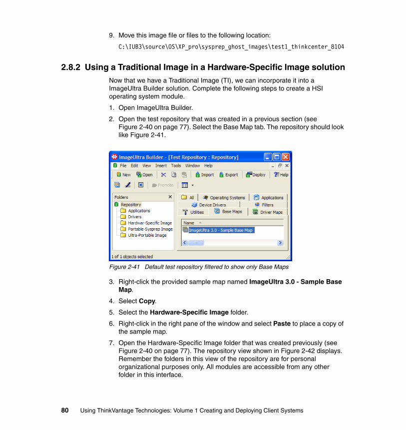
9. Move this image file or files to the following location:
C:\IUB3\source\OS\XP_pro\sysprep_ghost_images\test1_thinkcenter_8104
2.8.2 Using a Traditional Image in a Hardware-Specific Image solutionNow that we have a Traditional Image (TI), we can incorporate it into a ImageUltra Builder solution. Complete the following steps to create a HSI operating system module.
1. Open ImageUltra Builder.
2. Open the test repository that was created in a previous section (see Figure 2-40 on page 77). Select the Base Map tab. The repository should look like Figure 2-41.
Figure 2-41 Default test repository filtered to show only Base Maps
3. Right-click the provided sample map named ImageUltra 3.0 - Sample Base Map.
4. Select Copy.
5. Select the Hardware-Specific Image folder.
6. Right-click in the right pane of the window and select Paste to place a copy of the sample map.
7. Open the Hardware-Specific Image folder that was created previously (see Figure 2-40 on page 77). The repository view shown in Figure 2-42 displays. Remember the folders in this view of the repository are for personal organizational purposes only. All modules are accessible from any other folder in this interface.
80 Using ThinkVantage Technologies: Volume 1 Creating and Deploying Client Systems
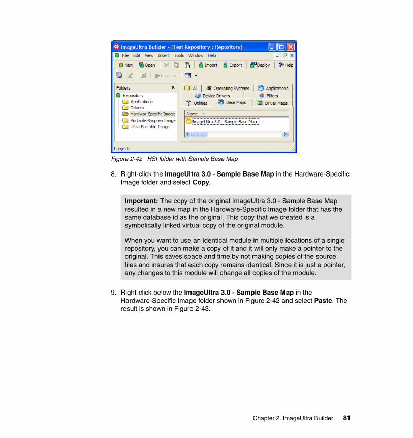
Figure 2-42 HSI folder with Sample Base Map
8. Right-click the ImageUltra 3.0 - Sample Base Map in the Hardware-Specific Image folder and select Copy.
9. Right-click below the ImageUltra 3.0 - Sample Base Map in the Hardware-Specific Image folder shown in Figure 2-42 and select Paste. The result is shown in Figure 2-43.
Important: The copy of the original ImageUltra 3.0 - Sample Base Map resulted in a new map in the Hardware-Specific Image folder that has the same database id as the original. This copy that we created is a symbolically linked virtual copy of the original module.
When you want to use an identical module in multiple locations of a single repository, you can make a copy of it and it will only make a pointer to the original. This saves space and time by not making copies of the source files and insures that each copy remains identical. Since it is just a pointer, any changes to this module will change all copies of the module.
Chapter 2. ImageUltra Builder 81
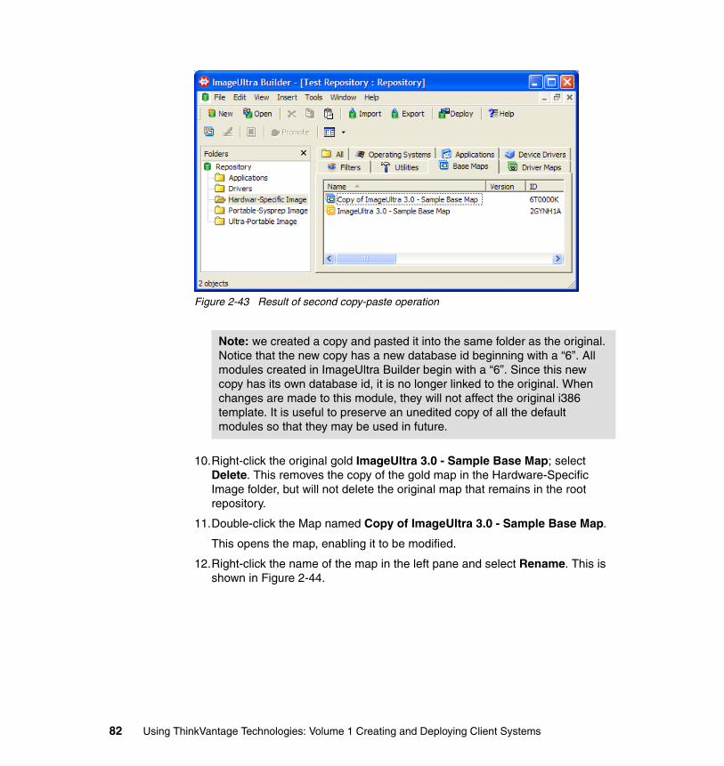
Figure 2-43 Result of second copy-paste operation
10.Right-click the original gold ImageUltra 3.0 - Sample Base Map; select Delete. This removes the copy of the gold map in the Hardware-Specific Image folder, but will not delete the original map that remains in the root repository.
11.Double-click the Map named Copy of ImageUltra 3.0 - Sample Base Map.
This opens the map, enabling it to be modified.
12.Right-click the name of the map in the left pane and select Rename. This is shown in Figure 2-44.
Note: we created a copy and pasted it into the same folder as the original. Notice that the new copy has a new database id beginning with a “6”. All modules created in ImageUltra Builder begin with a “6”. Since this new copy has its own database id, it is no longer linked to the original. When changes are made to this module, they will not affect the original i386 template. It is useful to preserve an unedited copy of all the default modules so that they may be used in future.
82 Using ThinkVantage Technologies: Volume 1 Creating and Deploying Client Systems
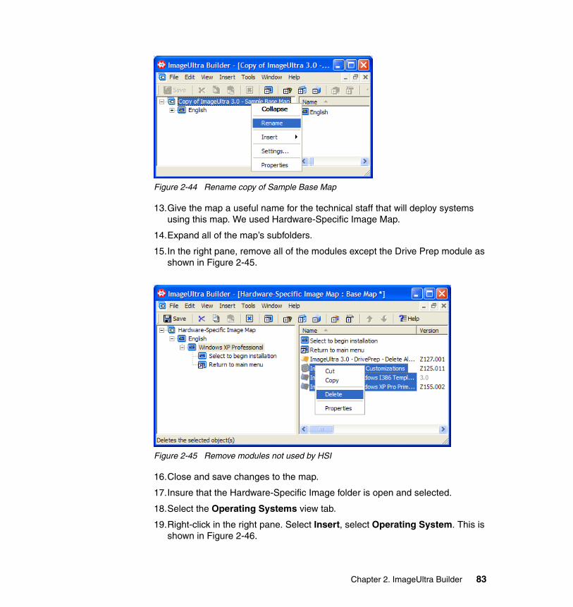
Figure 2-44 Rename copy of Sample Base Map
13.Give the map a useful name for the technical staff that will deploy systems using this map. We used Hardware-Specific Image Map.
14.Expand all of the map’s subfolders.
15.In the right pane, remove all of the modules except the Drive Prep module as shown in Figure 2-45.
Figure 2-45 Remove modules not used by HSI
16.Close and save changes to the map.
17.Insure that the Hardware-Specific Image folder is open and selected.
18.Select the Operating Systems view tab.
19.Right-click in the right pane. Select Insert, select Operating System. This is shown in Figure 2-46.
Chapter 2. ImageUltra Builder 83
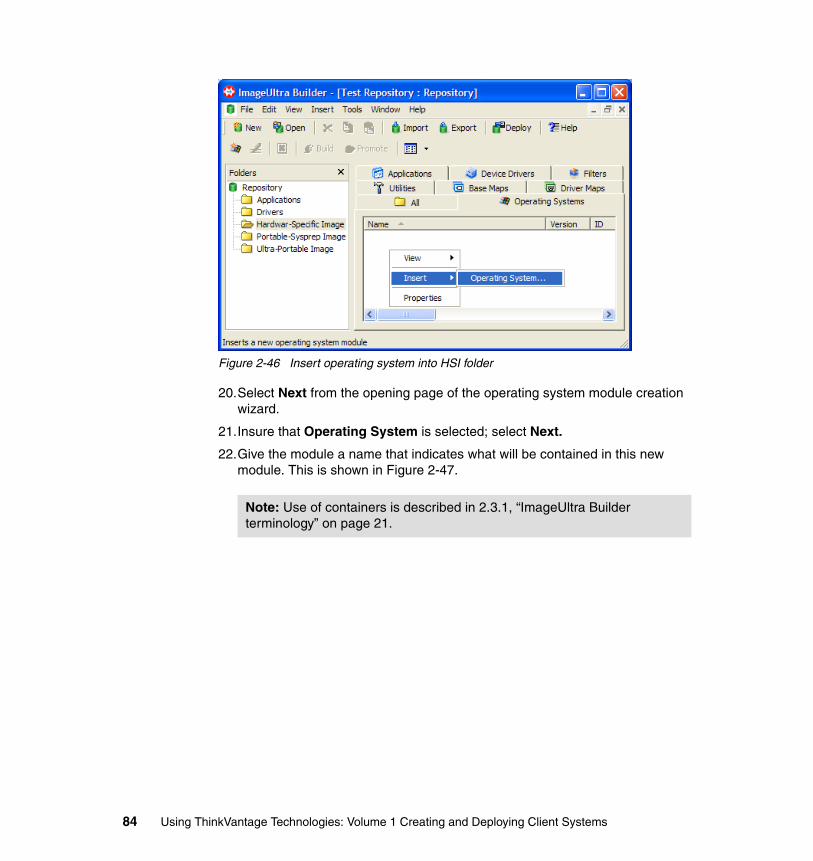
Figure 2-46 Insert operating system into HSI folder
20.Select Next from the opening page of the operating system module creation wizard.
21.Insure that Operating System is selected; select Next.
22.Give the module a name that indicates what will be contained in this new module. This is shown in Figure 2-47.
Note: Use of containers is described in 2.3.1, “ImageUltra Builder terminology” on page 21.
84 Using ThinkVantage Technologies: Volume 1 Creating and Deploying Client Systems
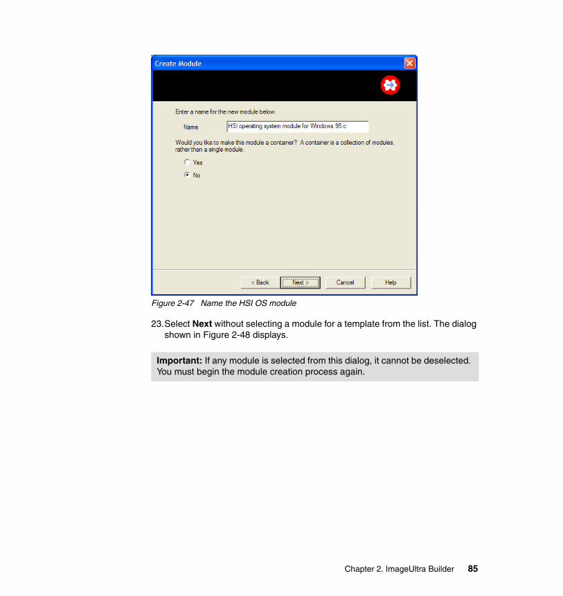
Figure 2-47 Name the HSI OS module
23.Select Next without selecting a module for a template from the list. The dialog shown in Figure 2-48 displays.
Important: If any module is selected from this dialog, it cannot be deselected. You must begin the module creation process again.
Chapter 2. ImageUltra Builder 85
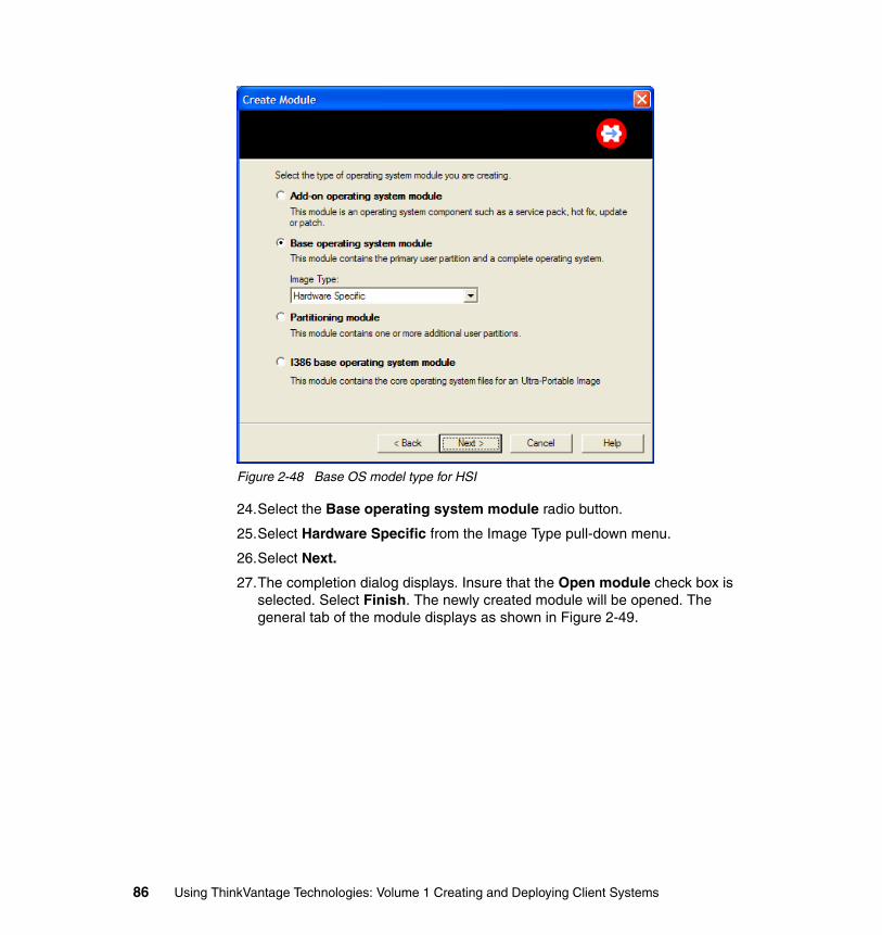
Figure 2-48 Base OS model type for HSI
24.Select the Base operating system module radio button.
25.Select Hardware Specific from the Image Type pull-down menu.
26.Select Next.
27.The completion dialog displays. Insure that the Open module check box is selected. Select Finish. The newly created module will be opened. The general tab of the module displays as shown in Figure 2-49.
86 Using ThinkVantage Technologies: Volume 1 Creating and Deploying Client Systems
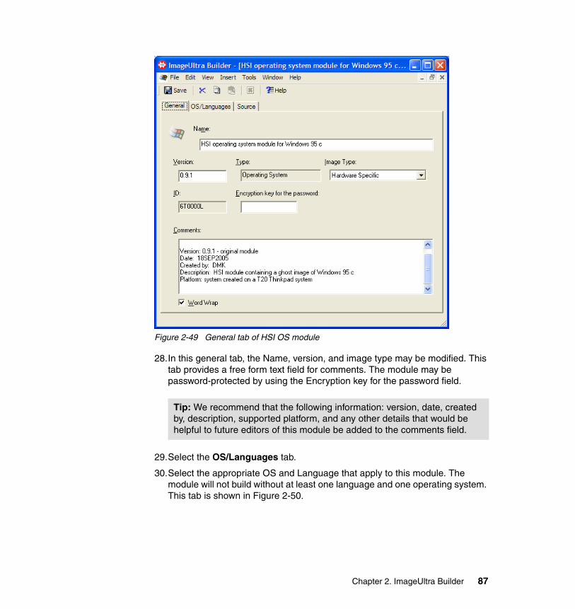
Figure 2-49 General tab of HSI OS module
28.In this general tab, the Name, version, and image type may be modified. This tab provides a free form text field for comments. The module may be password-protected by using the Encryption key for the password field.
29.Select the OS/Languages tab.
30.Select the appropriate OS and Language that apply to this module. The module will not build without at least one language and one operating system. This tab is shown in Figure 2-50.
Tip: We recommend that the following information: version, date, created by, description, supported platform, and any other details that would be helpful to future editors of this module be added to the comments field.
Chapter 2. ImageUltra Builder 87
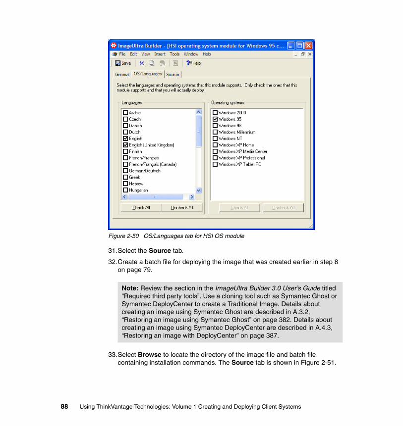
Figure 2-50 OS/Languages tab for HSI OS module
31.Select the Source tab.
32.Create a batch file for deploying the image that was created earlier in step 8 on page 79.
33.Select Browse to locate the directory of the image file and batch file containing installation commands. The Source tab is shown in Figure 2-51.
Note: Review the section in the ImageUltra Builder 3.0 User’s Guide titled “Required third party tools”. Use a cloning tool such as Symantec Ghost or Symantec DeployCenter to create a Traditional Image. Details about creating an image using Symantec Ghost are described in A.3.2, “Restoring an image using Symantec Ghost” on page 382. Details about creating an image using Symantec DeployCenter are described in A.4.3, “Restoring an image with DeployCenter” on page 387.
88 Using ThinkVantage Technologies: Volume 1 Creating and Deploying Client Systems
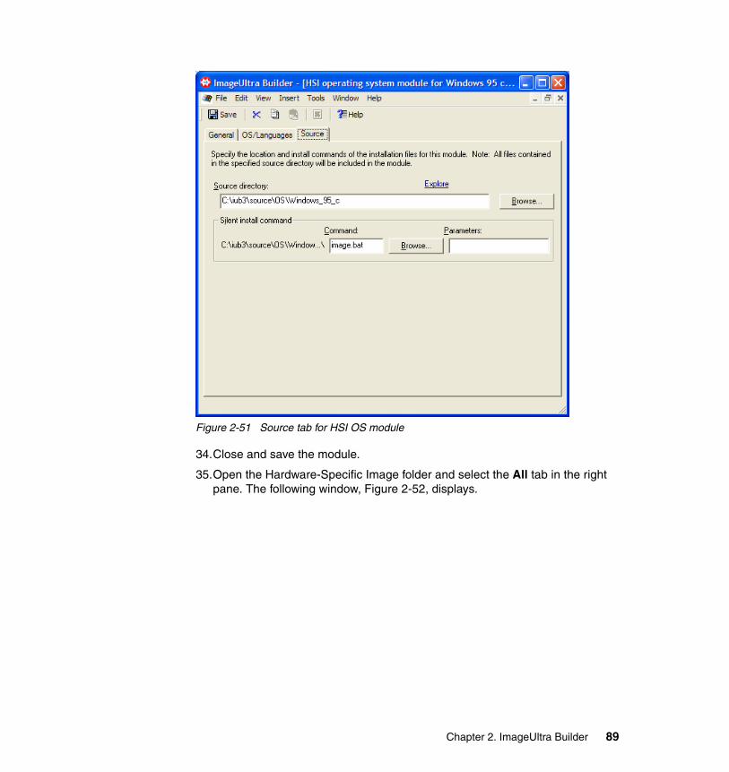
Figure 2-51 Source tab for HSI OS module
34.Close and save the module.
35.Open the Hardware-Specific Image folder and select the All tab in the right pane. The following window, Figure 2-52, displays.
Chapter 2. ImageUltra Builder 89
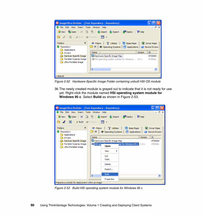
Figure 2-52 Hardware-Specific Image Folder containing unbuilt HSI OS module
36.The newly created module is grayed out to indicate that it is not ready for use yet. Right-click the module named HSI operating system module for Windows 95 c. Select Build as shown in Figure 2-53.
Figure 2-53 Build HSI operating system module for Windows 95 c
90 Using ThinkVantage Technologies: Volume 1 Creating and Deploying Client Systems
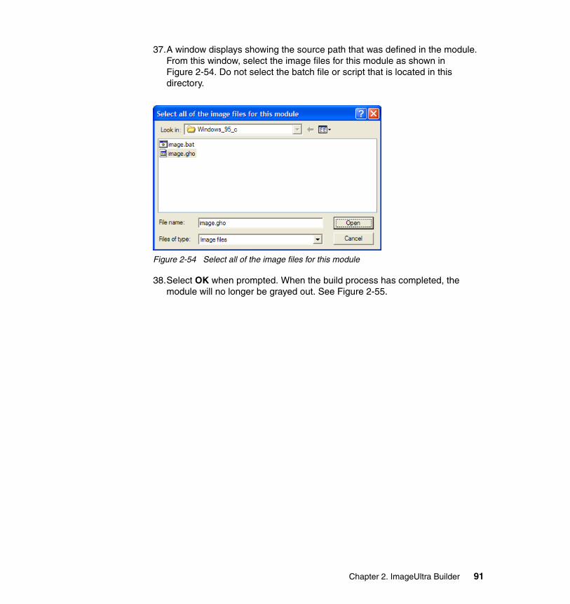
37.A window displays showing the source path that was defined in the module. From this window, select the image files for this module as shown in Figure 2-54. Do not select the batch file or script that is located in this directory.
Figure 2-54 Select all of the image files for this module
38.Select OK when prompted. When the build process has completed, the module will no longer be grayed out. See Figure 2-55.
Chapter 2. ImageUltra Builder 91
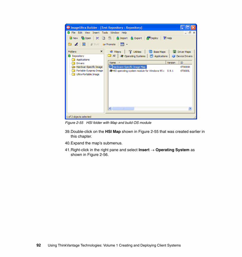
Figure 2-55 HSI folder with Map and build OS module
39.Double-click on the HSI Map shown in Figure 2-55 that was created earlier in this chapter.
40.Expand the map’s submenus.
41.Right-click in the right pane and select Insert → Operating System as shown in Figure 2-56.
92 Using ThinkVantage Technologies: Volume 1 Creating and Deploying Client Systems
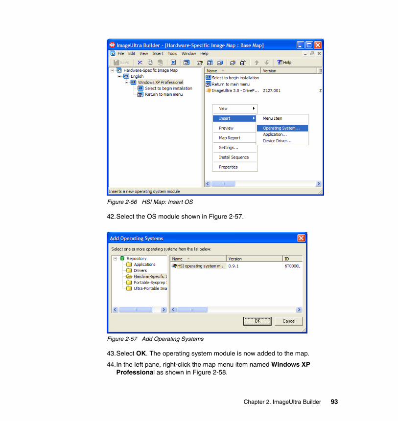
Figure 2-56 HSI Map: Insert OS
42.Select the OS module shown in Figure 2-57.
Figure 2-57 Add Operating Systems
43.Select OK. The operating system module is now added to the map.
44.In the left pane, right-click the map menu item named Windows XP Professional as shown in Figure 2-58.
Chapter 2. ImageUltra Builder 93
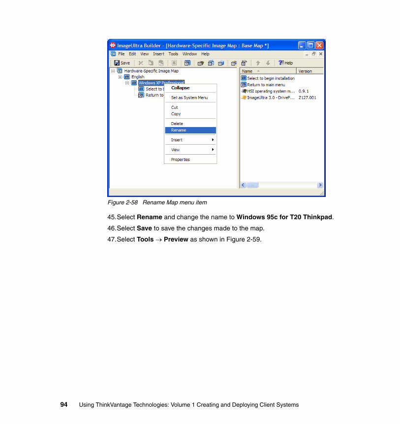
Figure 2-58 Rename Map menu item
45.Select Rename and change the name to Windows 95c for T20 Thinkpad.
46.Select Save to save the changes made to the map.
47.Select Tools → Preview as shown in Figure 2-59.
94 Using ThinkVantage Technologies: Volume 1 Creating and Deploying Client Systems
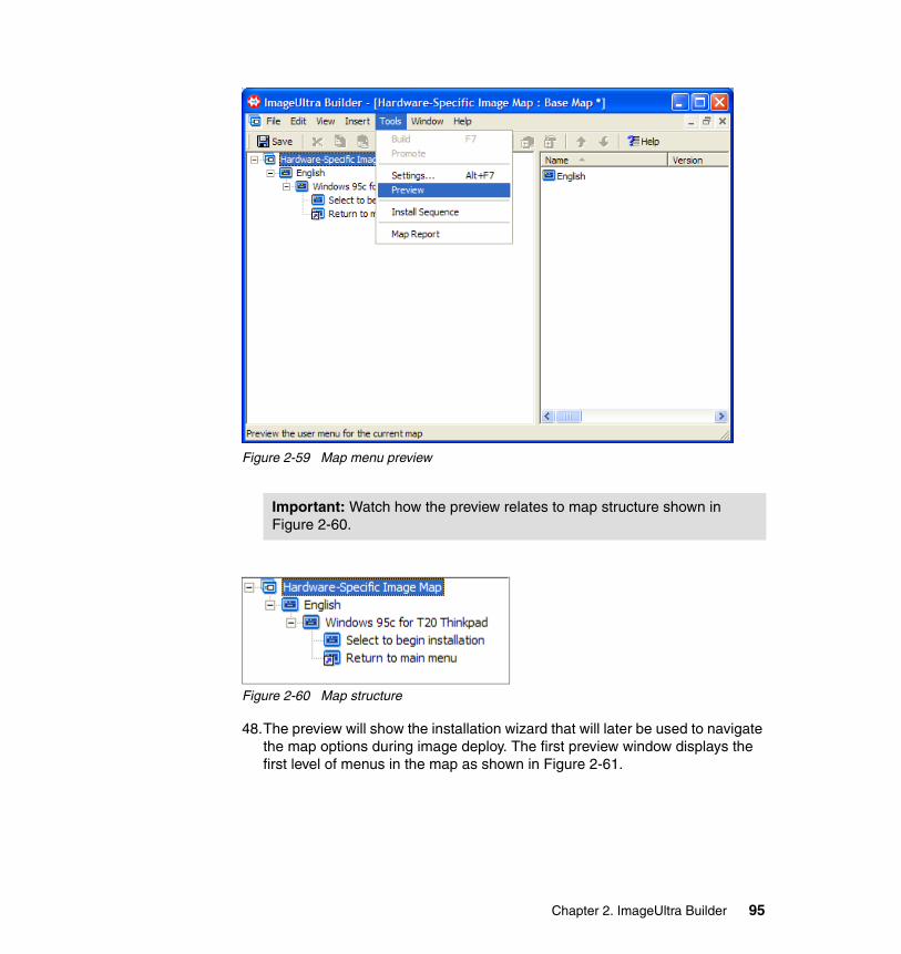
Figure 2-59 Map menu preview
Figure 2-60 Map structure
48.The preview will show the installation wizard that will later be used to navigate the map options during image deploy. The first preview window displays the first level of menus in the map as shown in Figure 2-61.
Important: Watch how the preview relates to map structure shown in Figure 2-60.
Chapter 2. ImageUltra Builder 95
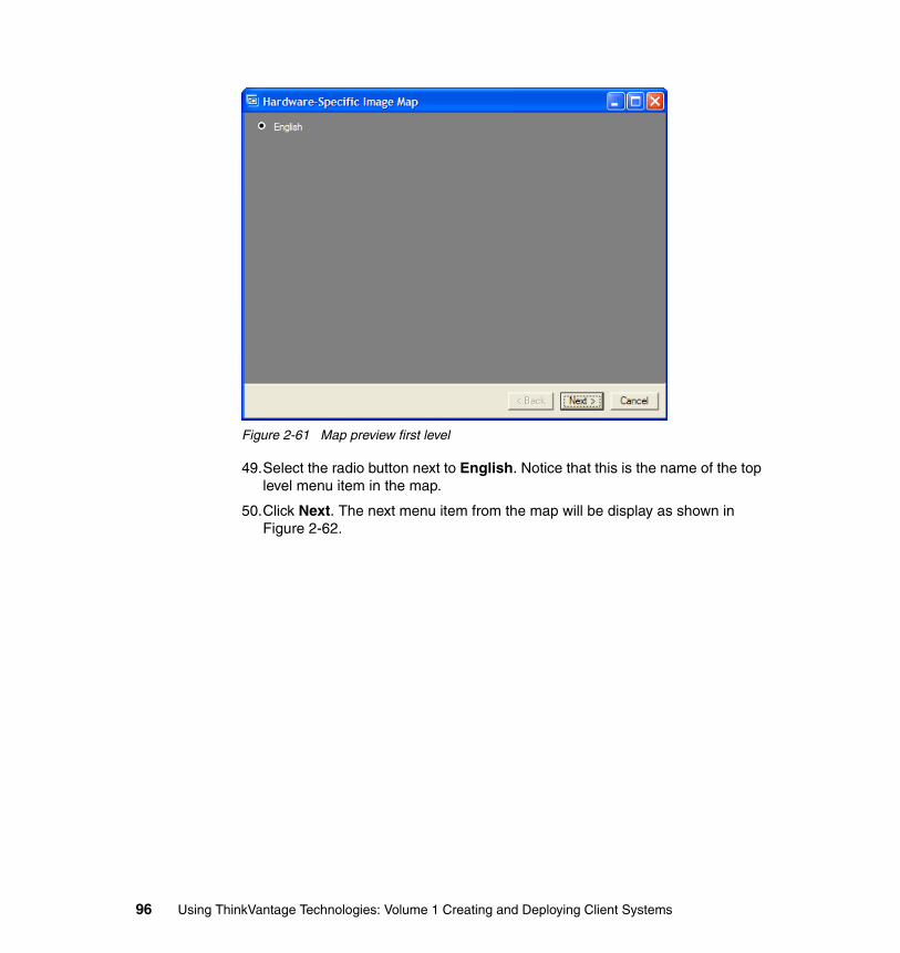
Figure 2-61 Map preview first level
49.Select the radio button next to English. Notice that this is the name of the top level menu item in the map.
50.Click Next. The next menu item from the map will be display as shown in Figure 2-62.
96 Using ThinkVantage Technologies: Volume 1 Creating and Deploying Client Systems
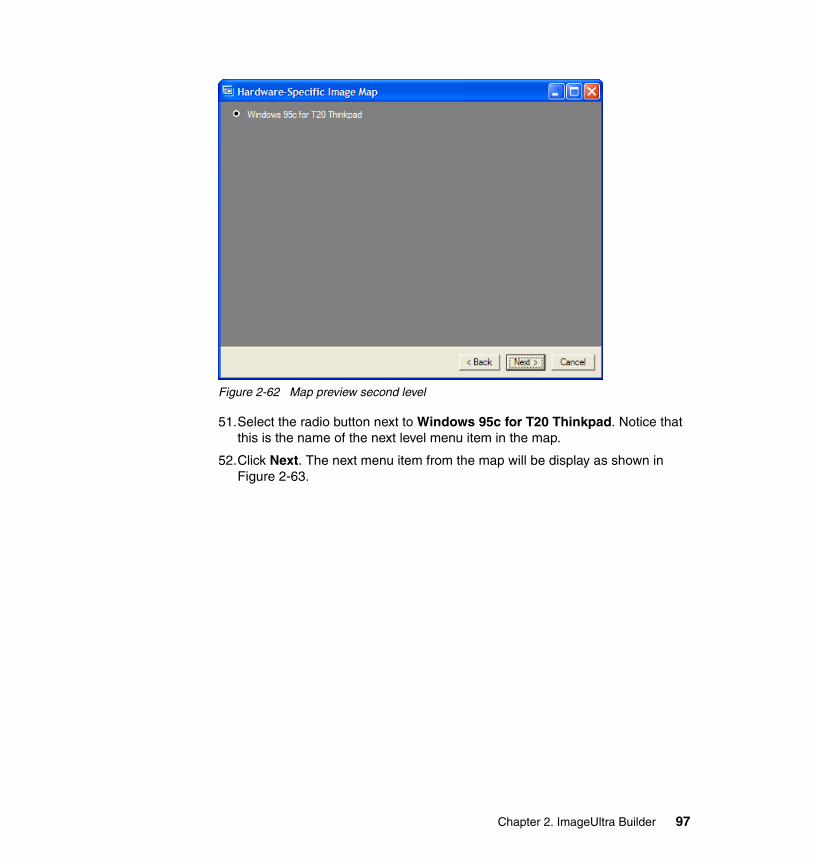
Figure 2-62 Map preview second level
51.Select the radio button next to Windows 95c for T20 Thinkpad. Notice that this is the name of the next level menu item in the map.
52.Click Next. The next menu item from the map will be display as shown in Figure 2-63.
Chapter 2. ImageUltra Builder 97
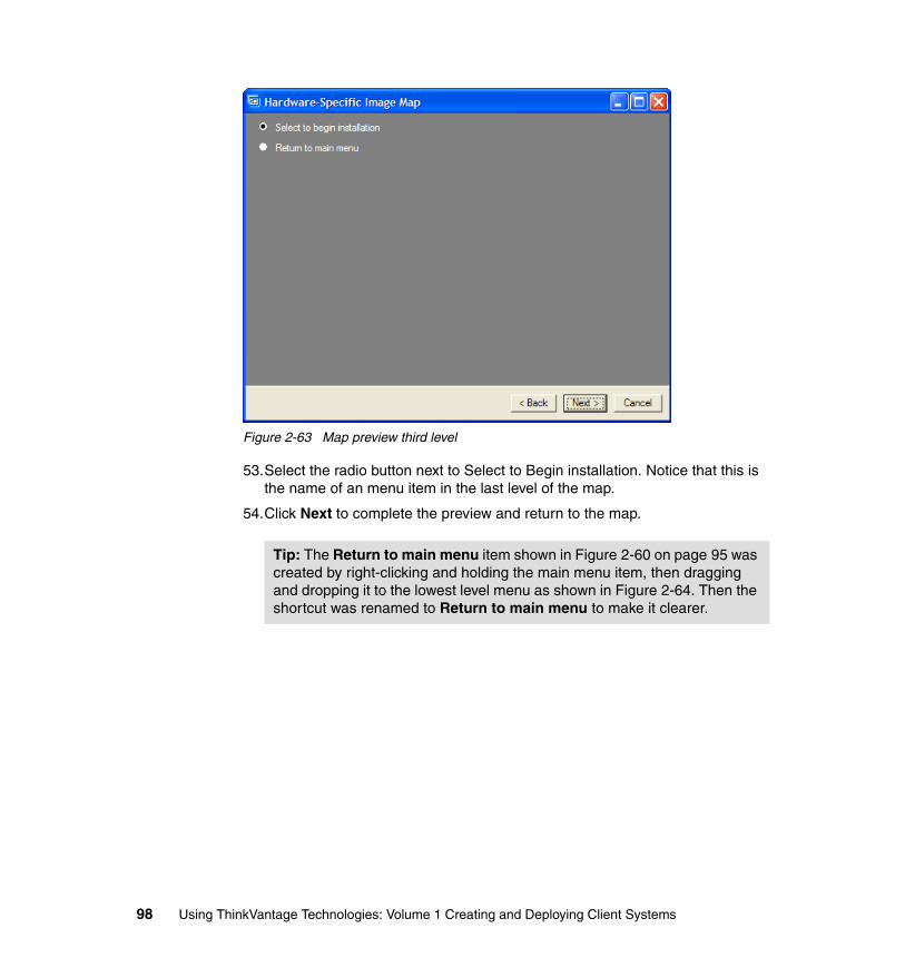
Figure 2-63 Map preview third level
53.Select the radio button next to Select to Begin installation. Notice that this is the name of an menu item in the last level of the map.
54.Click Next to complete the preview and return to the map.
Tip: The Return to main menu item shown in Figure 2-60 on page 95 was created by right-clicking and holding the main menu item, then dragging and dropping it to the lowest level menu as shown in Figure 2-64. Then the shortcut was renamed to Return to main menu to make it clearer.
98 Using ThinkVantage Technologies: Volume 1 Creating and Deploying Client Systems
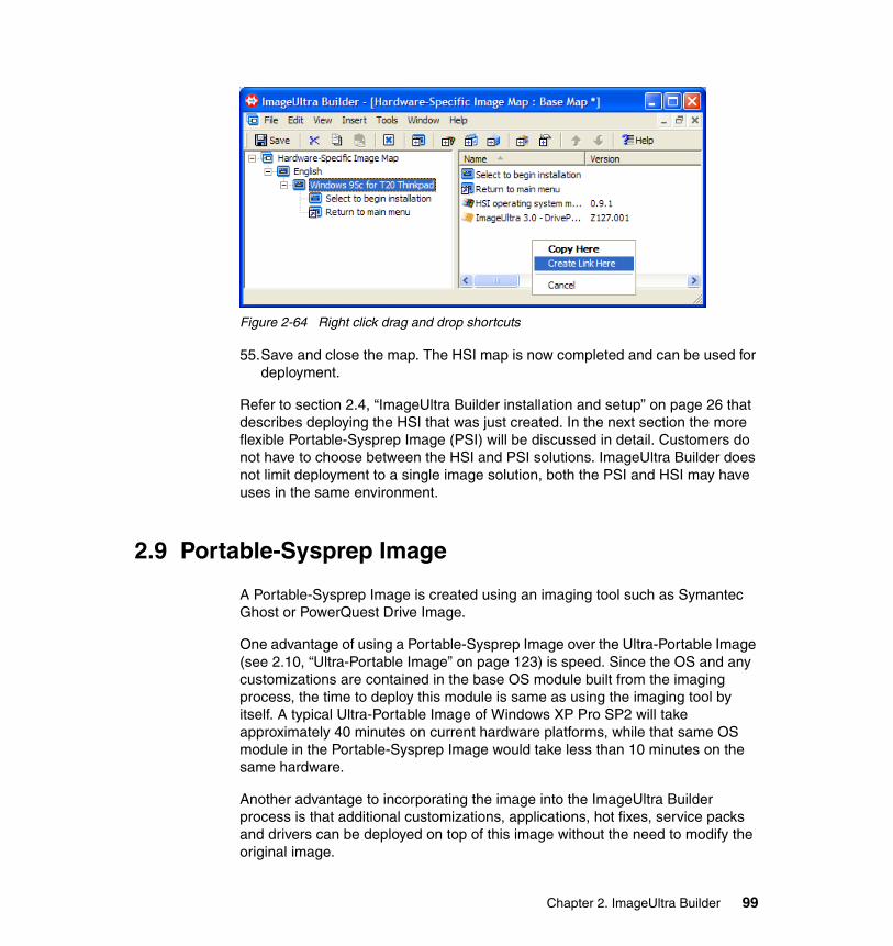
Figure 2-64 Right click drag and drop shortcuts
55.Save and close the map. The HSI map is now completed and can be used for deployment.
Refer to section 2.4, “ImageUltra Builder installation and setup” on page 26 that describes deploying the HSI that was just created. In the next section the more flexible Portable-Sysprep Image (PSI) will be discussed in detail. Customers do not have to choose between the HSI and PSI solutions. ImageUltra Builder does not limit deployment to a single image solution, both the PSI and HSI may have uses in the same environment.
2.9 Portable-Sysprep Image
A Portable-Sysprep Image is created using an imaging tool such as Symantec Ghost or PowerQuest Drive Image.
One advantage of using a Portable-Sysprep Image over the Ultra-Portable Image (see 2.10, “Ultra-Portable Image” on page 123) is speed. Since the OS and any customizations are contained in the base OS module built from the imaging process, the time to deploy this module is same as using the imaging tool by itself. A typical Ultra-Portable Image of Windows XP Pro SP2 will take approximately 40 minutes on current hardware platforms, while that same OS module in the Portable-Sysprep Image would take less than 10 minutes on the same hardware.
Another advantage to incorporating the image into the ImageUltra Builder process is that additional customizations, applications, hot fixes, service packs and drivers can be deployed on top of this image without the need to modify the original image.
Chapter 2. ImageUltra Builder 99
The limitation of the Portable-Sysprep Image is the base image hardware requirements. If the base image cannot be deployed successfully to a particular hardware platform, then any Portable-Sysprep Image created using that base image will not deploy successfully to that platform. The most common hardware limitation is caused by an incompatible Hardware Abstraction Layer (HAL) of the OS.
You must complete the following process in order for the ImageUltra Builder process to use the imaged OS for its basis for a Portable-Sysprep Image.
2.9.1 Preparing the seed system for the Portable-Sysprep Image1. Install a supported Operating System on the seed system. The following is a
list of systems supported by the PSI solution.
Supported operating systems
– Windows 2000– Windows XP Home– Windows XP Media Center– Windows XP Professional– Windows XP Tablet
2. Copy the ImageUltra Builder Customization Program (IUBCP.EXE) to a temporary folder on the seed system. This utility can be found in the IUBCP folder in the root of each repository. In our example repository, it is located in C:\IUB3\repo\iubcp.
3. Run the ImageUltra Customization Program (IUBCP.EXE).
a. Select Next.b. Select Install.c. Select Finish.
4. The Windows XP version of the sysprep program is on the Windows XP CD in the \SUPPORT\TOOLS\DEPLOY.CAB file. Extract the following three files from the deploy.cab file to the seed system in the C:\SYSPREP\ directory:
– factory.exe– setupcl.exe
Note: System names used in this section:
� A seed or donor system is a system used to develop and customize an operating system for use as a base OS module in the Portable-Sysprep Image process.
� A target system is the computer on which the IUB process is run to rebuild that system.
100 Using ThinkVantage Technologies: Volume 1 Creating and Deploying Client Systems
– sysprep.exe
5. Install any application programs that will be common across all of your target computers. If you have any applications that you cannot make into a module, now is the time to install them.
6. Make any required changes to C:\IBMWORK\SYSPREP.INF. This file is used to reenter the auditboot mode. You might change a password, set PID, and so on. Note: You may have to update PID information. In Windows XP, the easiest place to modify the PID information is in C:\IBMWORK\PROKEYP.FM.
7. Edit the OEMPNPPATH if you are using your own driver pnp path or use the default IUB OEMPNPPath.
8. Customize the look and feel of the operating system.
9. Remove all unnecessary files from the system.
10.Close all programs and shut down any unnecessary services.
11.Remove the Admin password by setting it to “(Blank)”.
12.Remove all installed hardware devices. If you have ImageUltra Builder version 2.x, copy the DDREMOVE.EXE and DMCLEAN.CMD files to the seed system. Execute the DMCLEAN.CMD. These tools will remove all devices that do not have native OS support. For example, USB mouse support will be removed during the execution of these utilities.
13.Open a command-line window.
14.Run SYSPREP.EXE using the following command:
C:\SYSPREP\SYSPREP.EXE -factory -quiet
15.Create an image of the system.
Note: This step is optional. You can include common applications as part of your operating-system module or you can build separate application modules and control them through your base map.
Note: Review the section in the ImageUltra Builder 3.0 User’s Guide titled “Required third party tools”. Use a cloning tool such as Symantec Ghost or Symantec DeployCenter to create a TI. Details about creating an image using Symantec Ghost are described in A.3.1, “Creating an image using Symantec Ghost” on page 382. Details about creating an image using Symantec DeployCenter are described in A.4.2, “Creating an image using DeployCenter” on page 386.
Chapter 2. ImageUltra Builder 101
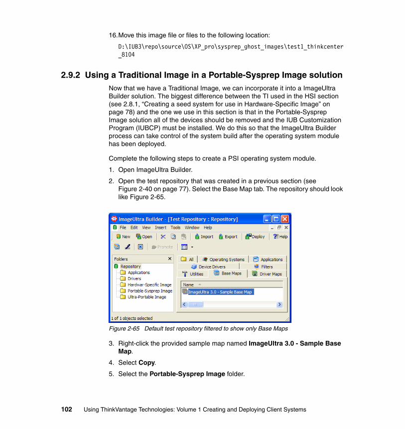
16.Move this image file or files to the following location:
D:\IUB3\repo\source\OS\XP_pro\sysprep_ghost_images\test1_thinkcenter_8104
2.9.2 Using a Traditional Image in a Portable-Sysprep Image solutionNow that we have a Traditional Image, we can incorporate it into a ImageUltra Builder solution. The biggest difference between the TI used in the HSI section (see 2.8.1, “Creating a seed system for use in Hardware-Specific Image” on page 78) and the one we use in this section is that in the Portable-Sysprep Image solution all of the devices should be removed and the IUB Customization Program (IUBCP) must be installed. We do this so that the ImageUltra Builder process can take control of the system build after the operating system module has been deployed.
Complete the following steps to create a PSI operating system module.
1. Open ImageUltra Builder.
2. Open the test repository that was created in a previous section (see Figure 2-40 on page 77). Select the Base Map tab. The repository should look like Figure 2-65.
Figure 2-65 Default test repository filtered to show only Base Maps
3. Right-click the provided sample map named ImageUltra 3.0 - Sample Base Map.
4. Select Copy.
5. Select the Portable-Sysprep Image folder.
102 Using ThinkVantage Technologies: Volume 1 Creating and Deploying Client Systems
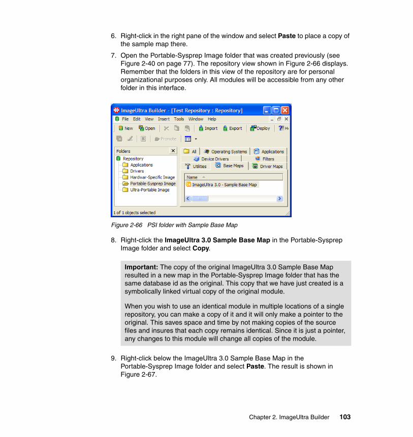
6. Right-click in the right pane of the window and select Paste to place a copy of the sample map there.
7. Open the Portable-Sysprep Image folder that was created previously (see Figure 2-40 on page 77). The repository view shown in Figure 2-66 displays. Remember that the folders in this view of the repository are for personal organizational purposes only. All modules will be accessible from any other folder in this interface.
Figure 2-66 PSI folder with Sample Base Map
8. Right-click the ImageUltra 3.0 Sample Base Map in the Portable-Sysprep Image folder and select Copy.
9. Right-click below the ImageUltra 3.0 Sample Base Map in the Portable-Sysprep Image folder and select Paste. The result is shown in Figure 2-67.
Important: The copy of the original ImageUltra 3.0 Sample Base Map resulted in a new map in the Portable-Sysprep Image folder that has the same database id as the original. This copy that we have just created is a symbolically linked virtual copy of the original module.
When you wish to use an identical module in multiple locations of a single repository, you can make a copy of it and it will only make a pointer to the original. This saves space and time by not making copies of the source files and insures that each copy remains identical. Since it is just a pointer, any changes to this module will change all copies of the module.
Chapter 2. ImageUltra Builder 103
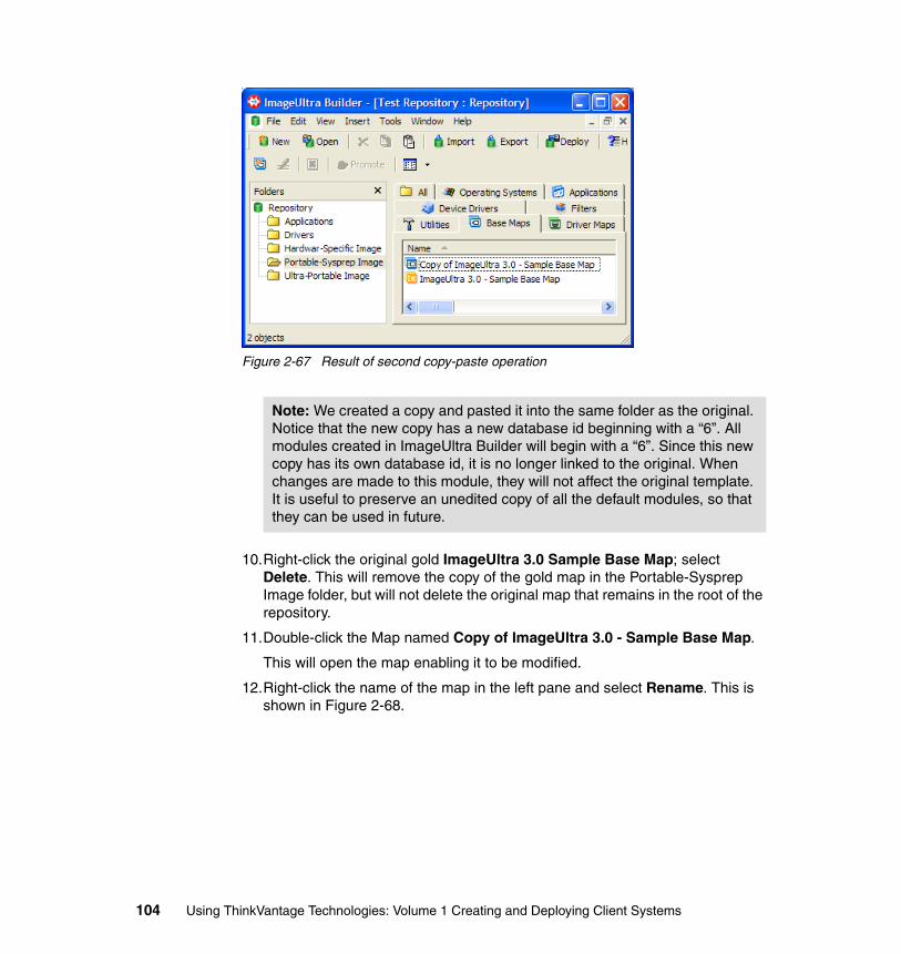
Figure 2-67 Result of second copy-paste operation
10.Right-click the original gold ImageUltra 3.0 Sample Base Map; select Delete. This will remove the copy of the gold map in the Portable-Sysprep Image folder, but will not delete the original map that remains in the root of the repository.
11.Double-click the Map named Copy of ImageUltra 3.0 - Sample Base Map.
This will open the map enabling it to be modified.
12.Right-click the name of the map in the left pane and select Rename. This is shown in Figure 2-68.
Note: We created a copy and pasted it into the same folder as the original. Notice that the new copy has a new database id beginning with a “6”. All modules created in ImageUltra Builder will begin with a “6”. Since this new copy has its own database id, it is no longer linked to the original. When changes are made to this module, they will not affect the original template. It is useful to preserve an unedited copy of all the default modules, so that they can be used in future.
104 Using ThinkVantage Technologies: Volume 1 Creating and Deploying Client Systems

Figure 2-68 Rename copy of Sample Base Map
13.Give the map a useful name for the technical staff that will deploy systems using this map. In the example, we used the name Portable-Sysprep Image for the title of the Map.
14.Expand all of the map’s subfolders. See Figure 2-69.
Figure 2-69 Remove the modules unused by PSI
15.In the right pane, delete the ImageUltra 3.0 - DrivePrep - Delete All Partitions, ImageUltra 3.0 - IBM Customizations, ImageUltra 3.0 - Windows I386 Template, and ImageUltra 3.0 - Windows XP Pro Primary Partition modules as shown in Figure 2-69.
Chapter 2. ImageUltra Builder 105
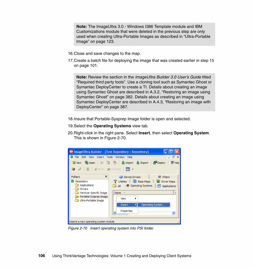
16.Close and save changes to the map.
17.Create a batch file for deploying the image that was created earlier in step 15 on page 101.
18.Insure that Portable-Sysprep Image folder is open and selected.
19.Select the Operating Systems view tab.
20.Right-click in the right pane. Select Insert, then select Operating System. This is shown in Figure 2-70.
Figure 2-70 Insert operating system into PSI folder
Note: The ImageUltra 3.0 - Windows I386 Template module and IBM Customizations module that were deleted in the previous step are only used when creating Ultra-Portable Images as described in “Ultra-Portable Image” on page 123.
Note: Review the section in the ImageUltra Builder 3.0 User’s Guide titled “Required third party tools”. Use a cloning tool such as Symantec Ghost or Symantec DeployCenter to create a TI. Details about creating an image using Symantec Ghost are described in A.3.2, “Restoring an image using Symantec Ghost” on page 382. Details about creating an image using Symantec DeployCenter are described in A.4.3, “Restoring an image with DeployCenter” on page 387.
106 Using ThinkVantage Technologies: Volume 1 Creating and Deploying Client Systems
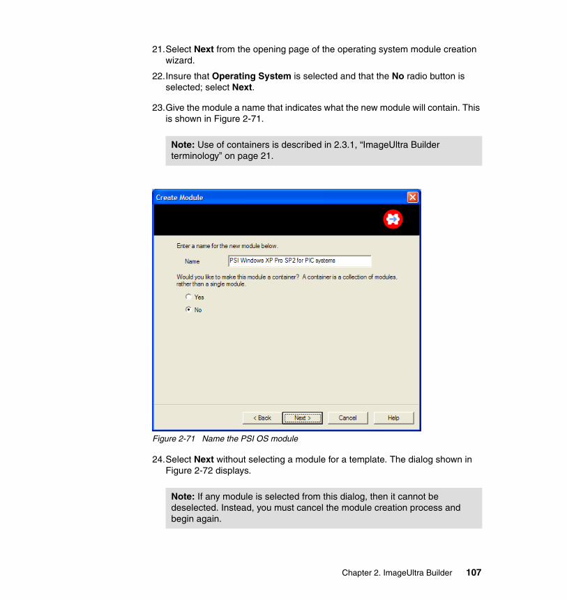
21.Select Next from the opening page of the operating system module creation wizard.
22.Insure that Operating System is selected and that the No radio button is selected; select Next.
23.Give the module a name that indicates what the new module will contain. This is shown in Figure 2-71.
Figure 2-71 Name the PSI OS module
24.Select Next without selecting a module for a template. The dialog shown in Figure 2-72 displays.
Note: Use of containers is described in 2.3.1, “ImageUltra Builder terminology” on page 21.
Note: If any module is selected from this dialog, then it cannot be deselected. Instead, you must cancel the module creation process and begin again.
Chapter 2. ImageUltra Builder 107

Figure 2-72 Base OS model type for PSI
25.Select the Base operating system module radio button.
26.Select Portable Sysprep from the pull-down menu.
27.Select Next.
28.The completion dialog displays. Insure that the Open module check box is selected. Select Finish. The newly created module will be opened. The General tab of the module displays as shown in Figure 2-73.
108 Using ThinkVantage Technologies: Volume 1 Creating and Deploying Client Systems
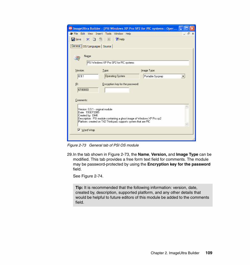
Figure 2-73 General tab of PSI OS module
29.In the tab shown in Figure 2-73, the Name, Version, and Image Type can be modified. This tab provides a free form text field for comments. The module may be password-protected by using the Encryption key for the password field.
See Figure 2-74.
Tip: It is recommended that the following information: version, date, created by, description, supported platform, and any other details that would be helpful to future editors of this module be added to the comments field.
Chapter 2. ImageUltra Builder 109
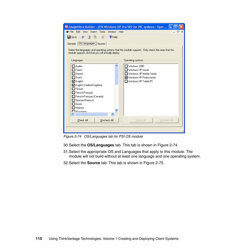
Figure 2-74 OS/Languages tab for PSI OS module
30.Select the OS/Languages tab. This tab is shown in Figure 2-74.
31.Select the appropriate OS and Languages that apply to this module. The module will not build without at least one language and one operating system.
32.Select the Source tab. This tab is shown in Figure 2-75.
110 Using ThinkVantage Technologies: Volume 1 Creating and Deploying Client Systems
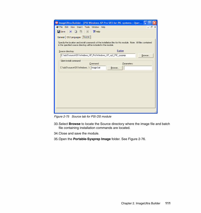
Figure 2-75 Source tab for PSI OS module
33.Select Browse to locate the Source directory where the image file and batch file containing installation commands are located.
34.Close and save the module.
35.Open the Portable-Sysprep Image folder. See Figure 2-76.
Chapter 2. ImageUltra Builder 111
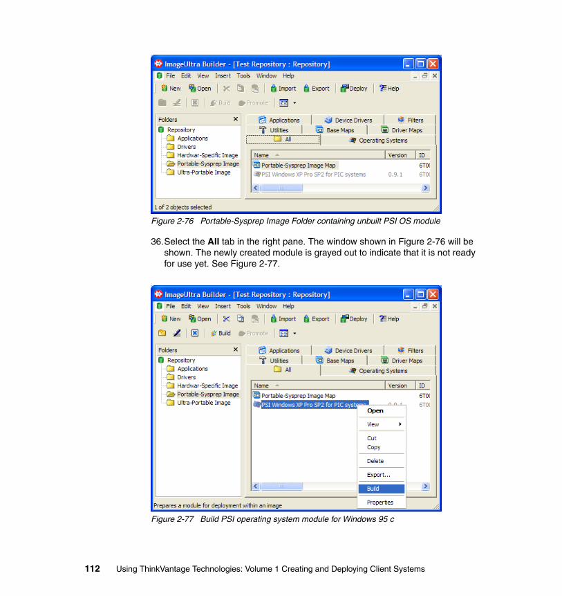
Figure 2-76 Portable-Sysprep Image Folder containing unbuilt PSI OS module
36.Select the All tab in the right pane. The window shown in Figure 2-76 will be shown. The newly created module is grayed out to indicate that it is not ready for use yet. See Figure 2-77.
Figure 2-77 Build PSI operating system module for Windows 95 c
112 Using ThinkVantage Technologies: Volume 1 Creating and Deploying Client Systems
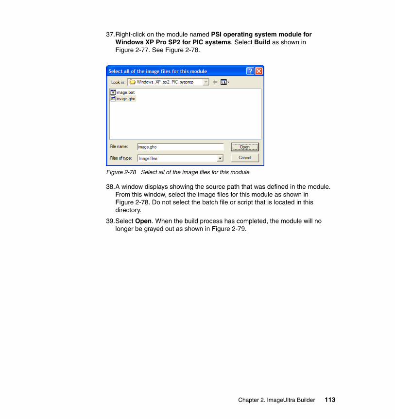
37.Right-click on the module named PSI operating system module for Windows XP Pro SP2 for PIC systems. Select Build as shown in Figure 2-77. See Figure 2-78.
Figure 2-78 Select all of the image files for this module
38.A window displays showing the source path that was defined in the module. From this window, select the image files for this module as shown in Figure 2-78. Do not select the batch file or script that is located in this directory.
39.Select Open. When the build process has completed, the module will no longer be grayed out as shown in Figure 2-79.
Chapter 2. ImageUltra Builder 113
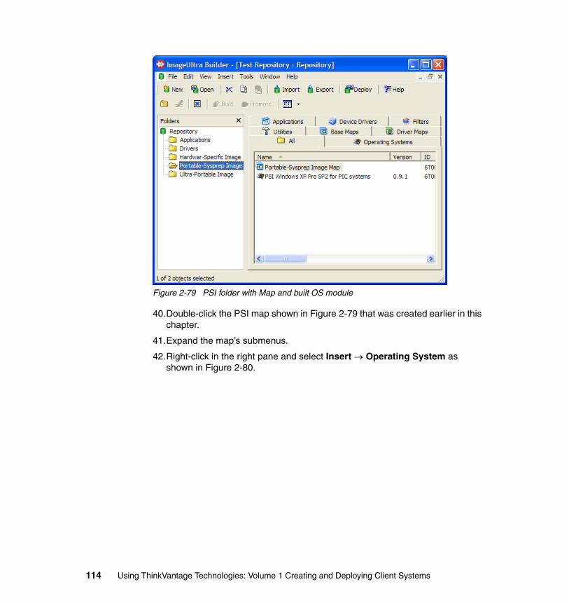
Figure 2-79 PSI folder with Map and built OS module
40.Double-click the PSI map shown in Figure 2-79 that was created earlier in this chapter.
41.Expand the map’s submenus.
42.Right-click in the right pane and select Insert → Operating System as shown in Figure 2-80.
114 Using ThinkVantage Technologies: Volume 1 Creating and Deploying Client Systems
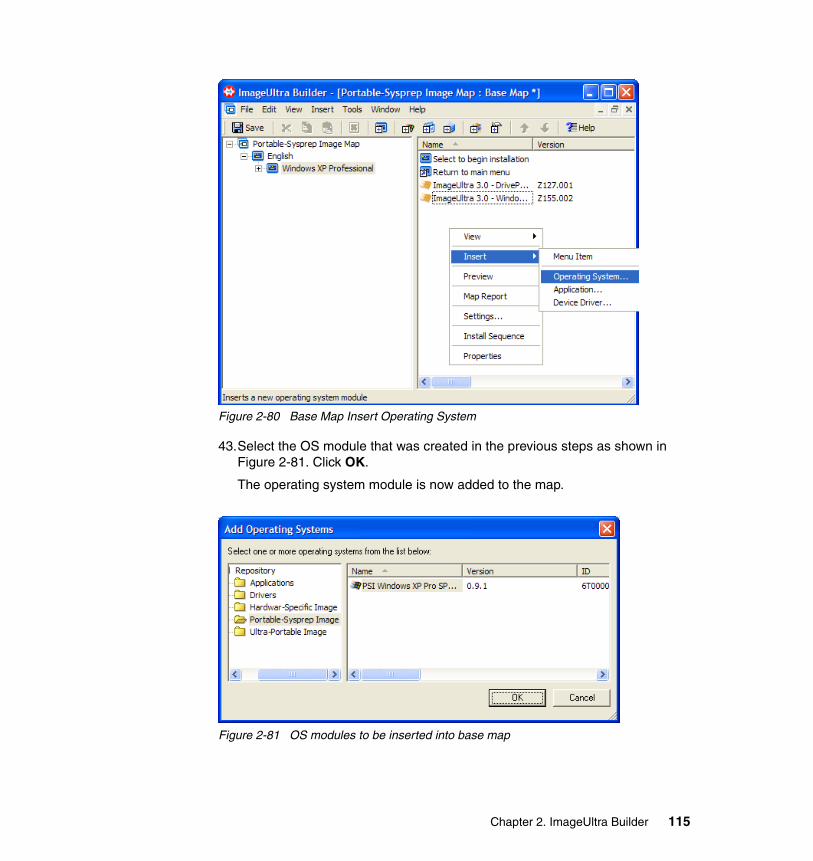
Figure 2-80 Base Map Insert Operating System
43.Select the OS module that was created in the previous steps as shown in Figure 2-81. Click OK.
The operating system module is now added to the map.
Figure 2-81 OS modules to be inserted into base map
Chapter 2. ImageUltra Builder 115
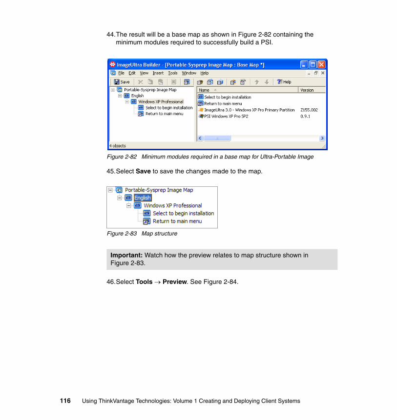
44.The result will be a base map as shown in Figure 2-82 containing the minimum modules required to successfully build a PSI.
Figure 2-82 Minimum modules required in a base map for Ultra-Portable Image
45.Select Save to save the changes made to the map.
Figure 2-83 Map structure
46.Select Tools → Preview. See Figure 2-84.
Important: Watch how the preview relates to map structure shown in Figure 2-83.
116 Using ThinkVantage Technologies: Volume 1 Creating and Deploying Client Systems

Figure 2-84 Map preview
47.The preview will show the installation wizard that will be used to navigate the map options later during image deploy. The first preview window displays the first level of menus in the map as shown in Figure 2-85.
Chapter 2. ImageUltra Builder 117
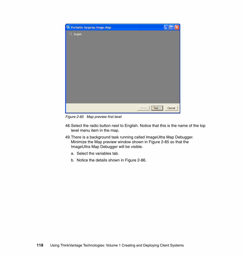
Figure 2-85 Map preview first level
48.Select the radio button next to English. Notice that this is the name of the top level menu item in the map.
49.There is a background task running called ImageUltra Map Debugger. Minimize the Map preview window shown in Figure 2-85 so that the ImageUltra Map Debugger will be visible.
a. Select the variables tab.
b. Notice the details shown in Figure 2-86.
118 Using ThinkVantage Technologies: Volume 1 Creating and Deploying Client Systems
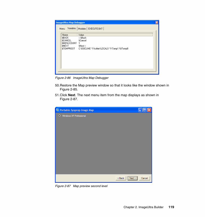
Figure 2-86 ImageUltra Map Debugger
50.Restore the Map preview window so that it looks like the window shown in Figure 2-85.
51.Click Next. The next menu item from the map displays as shown in Figure 2-87.
Figure 2-87 Map preview second level
Chapter 2. ImageUltra Builder 119
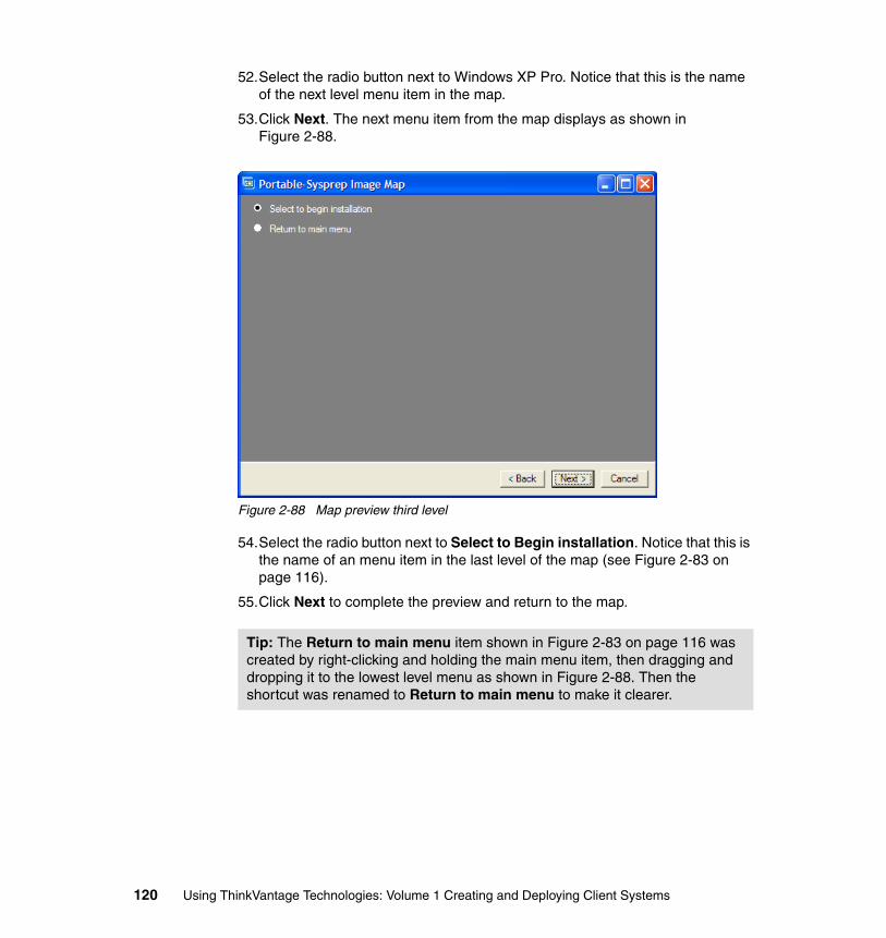
52.Select the radio button next to Windows XP Pro. Notice that this is the name of the next level menu item in the map.
53.Click Next. The next menu item from the map displays as shown in Figure 2-88.
Figure 2-88 Map preview third level
54.Select the radio button next to Select to Begin installation. Notice that this is the name of an menu item in the last level of the map (see Figure 2-83 on page 116).
55.Click Next to complete the preview and return to the map.
Tip: The Return to main menu item shown in Figure 2-83 on page 116 was created by right-clicking and holding the main menu item, then dragging and dropping it to the lowest level menu as shown in Figure 2-88. Then the shortcut was renamed to Return to main menu to make it clearer.
120 Using ThinkVantage Technologies: Volume 1 Creating and Deploying Client Systems
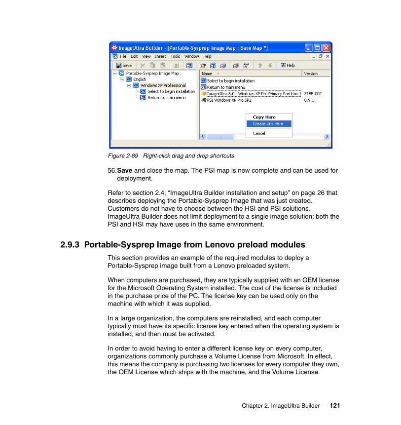
Figure 2-89 Right-click drag and drop shortcuts
56.Save and close the map. The PSI map is now complete and can be used for deployment.
Refer to section 2.4, “ImageUltra Builder installation and setup” on page 26 that describes deploying the Portable-Sysprep Image that was just created. Customers do not have to choose between the HSI and PSI solutions. ImageUltra Builder does not limit deployment to a single image solution; both the PSI and HSI may have uses in the same environment.
2.9.3 Portable-Sysprep Image from Lenovo preload modulesThis section provides an example of the required modules to deploy a Portable-Sysprep image built from a Lenovo preloaded system.
When computers are purchased, they are typically supplied with an OEM license for the Microsoft Operating System installed. The cost of the license is included in the purchase price of the PC. The license key can be used only on the machine with which it was supplied.
In a large organization, the computers are reinstalled, and each computer typically must have its specific license key entered when the operating system is installed, and then must be activated.
In order to avoid having to enter a different license key on every computer, organizations commonly purchase a Volume License from Microsoft. In effect, this means the company is purchasing two licenses for every computer they own, the OEM License which ships with the machine, and the Volume License.
Chapter 2. ImageUltra Builder 121
Prebuilt ImageUltra Builder modules are available on Lenovo preloaded systems and can be used to create new ImageUltra Builder system build images. The existing OS, applications, and driver modules can be imported from the service partition of a Lenovo PC. The process for importing modules is described in 2.5.10, “Import preload modules into the repository” on page 66.
There is a Base OS module, among the modules in the service partition, that is preconfigured with an OEM license key that can be used on only Lenovo or IBM systems. This Base Operating System module, in combination with a System Locked Preinstallation (SLP) module, provides a way to create an image using an OEM license that can be distributed to many computers.
The base map in Figure 2-90 lists the required modules to deploy the Portable Sysprep Image. The Windows XP sysprep image in this example utilizes the sysprep module “US XP PRO SP1a SYSPREP PIC BASE OS Module A GOLD” imported from the Lenovo preload. The name of this module will vary between different preloads (for information about PIC and APIC, refer to Appendix A.1, “Sysprep hardware limitations and HALs” on page 374).
122 Using ThinkVantage Technologies: Volume 1 Creating and Deploying Client Systems
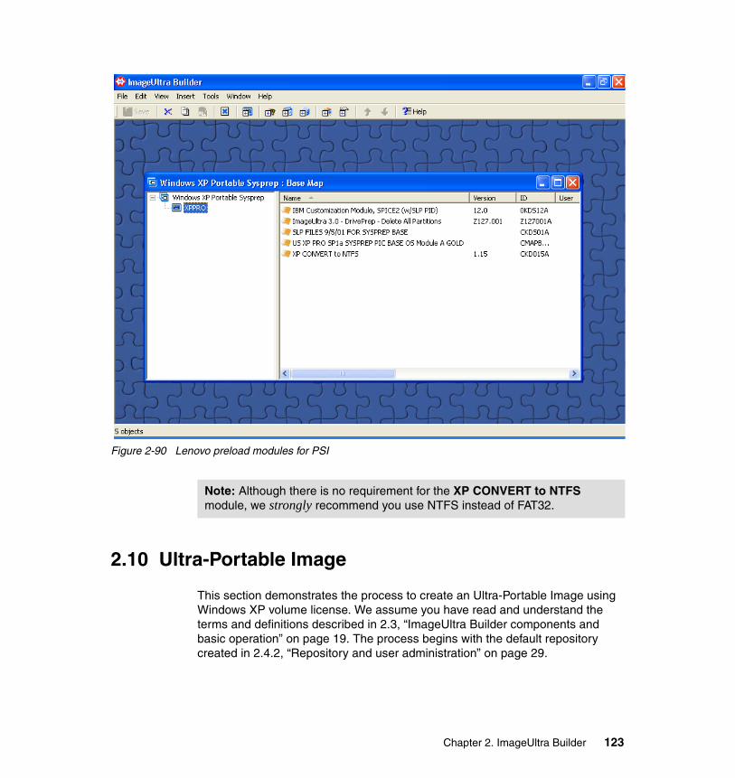
Figure 2-90 Lenovo preload modules for PSI
2.10 Ultra-Portable Image
This section demonstrates the process to create an Ultra-Portable Image using Windows XP volume license. We assume you have read and understand the terms and definitions described in 2.3, “ImageUltra Builder components and basic operation” on page 19. The process begins with the default repository created in 2.4.2, “Repository and user administration” on page 29.
Note: Although there is no requirement for the XP CONVERT to NTFS module, we strongly recommend you use NTFS instead of FAT32.
Chapter 2. ImageUltra Builder 123
PrerequisitesThis process requires the following software and keys:
1. Windows XP Pro installation CD.
2. Valid license for the Operating System. We recommend that you use a volume license due to the requirement we list in the above note.
3. Hardware drivers for any hardware that needs drivers that the OS installation does not supply.
4. Open Windows Explorer. Create the folder structure shown in Figure 2-91.
Note: You can use an OEM copy of the OS along with any valid license key from the license sticker on a PC or Laptop. Using an OEM version requires activation within 30 days of building the new system.
124 Using ThinkVantage Technologies: Volume 1 Creating and Deploying Client Systems
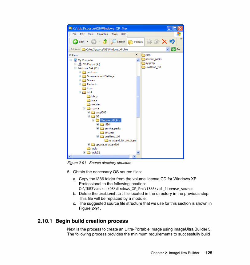
Figure 2-91 Source directory structure
5. Obtain the necessary OS source files:
a. Copy the i386 folder from the volume license CD for Windows XP Professional to the following location: C:\IUB3\source\OS\Windows_XP_Pro\i386\vol_license_source
b. Delete the unattend.txt file located in the directory in the previous step. This file will be replaced by a module.
c. The suggested source file structure that we use for this section is shown in Figure 2-91.
2.10.1 Begin build creation processNext is the process to create an Ultra-Portable Image using ImageUltra Builder 3. The following process provides the minimum requirements to successfully build
Chapter 2. ImageUltra Builder 125
an Ultra-Portable Image. We describe driver and application modules in detail in other sections and we do not require them for the successful deployment of this minimal build. When testing the build created by the following process, we recommend that you test the build without drivers first to insure that bugs in a driver module do not prevent the IUB process from completing. Then, you can add the required driver modules along with any additional application modules desired to make the build more useful.
1. We create the i386 OS module in this step. Complete the following steps to create the i386 OS module:
a. Copy the ImageUltra 3.0 - Windows I386 Template from the root directory of the repository and paste it into the Ultra-Portable Image folder.
b. Open the Ultra-Portable Image folder. Copy the ImageUltra 3.0 - Windows I386 Template and paste it into the same Ultra-Portable Image folder. The result is in Figure 2-92.
Tip: The copy of the original I386 module resulted in new module in the Ultra-Portable Image folder that has the same database id as the original. This copy that we created is a symbolically linked virtual copy of the original module.
When you want to use an identical module in multiple locations of a single repository, you can make a copy of it and it only makes a pointer to the original. This saves space and time by not making copies of the source files and insures that each copy remains identical. Since it is just a pointer, any changes to this module will change all copies of the module.
126 Using ThinkVantage Technologies: Volume 1 Creating and Deploying Client Systems
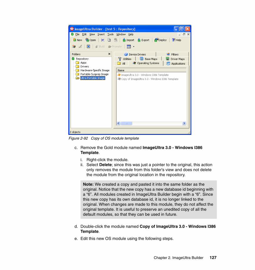
Figure 2-92 Copy of OS module template
c. Remove the Gold module named ImageUltra 3.0 - Windows I386 Template.
i. Right-click the module.ii. Select Delete; since this was just a pointer to the original, this action
only removes the module from this folder’s view and does not delete the module from the original location in the repository.
d. Double-click the module named Copy of ImageUltra 3.0 - Windows I386 Template.
e. Edit this new OS module using the following steps.
Note: We created a copy and pasted it into the same folder as the original. Notice that the new copy has a new database id beginning with a “6”. All modules created in ImageUltra Builder begin with a “6”. Since this new copy has its own database id, it is no longer linked to the original. When changes are made to this module, they do not affect the original template. It is useful to preserve an unedited copy of all the default modules, so that they can be used in future.
Chapter 2. ImageUltra Builder 127
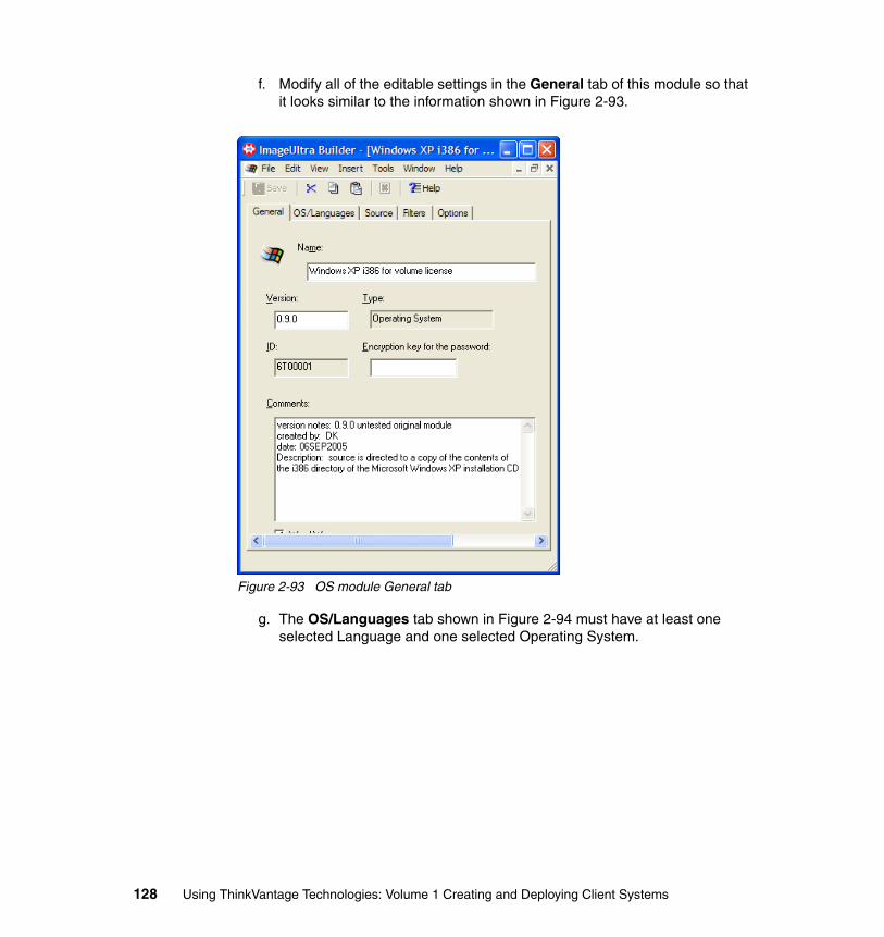
f. Modify all of the editable settings in the General tab of this module so that it looks similar to the information shown in Figure 2-93.
Figure 2-93 OS module General tab
g. The OS/Languages tab shown in Figure 2-94 must have at least one selected Language and one selected Operating System.
128 Using ThinkVantage Technologies: Volume 1 Creating and Deploying Client Systems
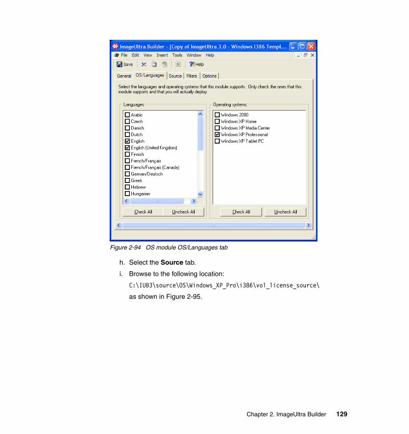
Figure 2-94 OS module OS/Languages tab
h. Select the Source tab.
i. Browse to the following location:
C:\IUB3\source\OS\Windows_XP_Pro\i386\vol_license_source\
as shown in Figure 2-95.
Chapter 2. ImageUltra Builder 129
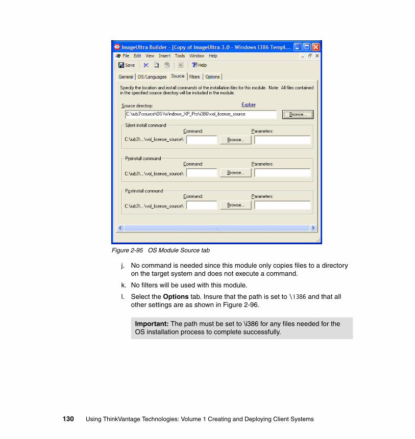
Figure 2-95 OS Module Source tab
j. No command is needed since this module only copies files to a directory on the target system and does not execute a command.
k. No filters will be used with this module.
l. Select the Options tab. Insure that the path is set to \i386 and that all other settings are as shown in Figure 2-96.
Important: The path must be set to \i386 for any files needed for the OS installation process to complete successfully.
130 Using ThinkVantage Technologies: Volume 1 Creating and Deploying Client Systems
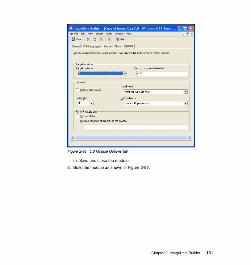
Figure 2-96 OS Module Options tab
m. Save and close the module.
2. Build the module as shown in Figure 2-97.
Chapter 2. ImageUltra Builder 131
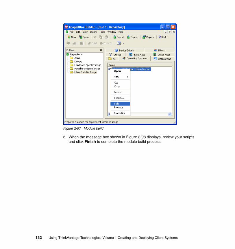
Figure 2-97 Module build
3. When the message box shown in Figure 2-98 displays, review your scripts and click Finish to complete the module build process.
132 Using ThinkVantage Technologies: Volume 1 Creating and Deploying Client Systems
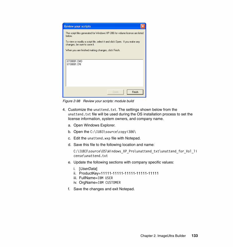
Figure 2-98 Review your scripts: module build
4. Customize the unattend.txt. The settings shown below from the unattend.txt file will be used during the OS installation process to set the license information, system owners, and company name.
a. Open Windows Explorer.
b. Open the C:\IUB3\source\copyi386\
c. Edit the unattend.wxp file with Notepad.
d. Save this file to the following location and name:
C:\IUB3\source\OS\Windows_XP_Pro\unattend_txt\unattend_for_Vol_license\unattend.txt
e. Update the following sections with company specific values:
i. [UserData]ii. ProductKey=11111-11111-11111-11111-11111iii. FullName=IBM USERiv. OrgName=IBM CUSTOMER
f. Save the changes and exit Notepad.
Chapter 2. ImageUltra Builder 133
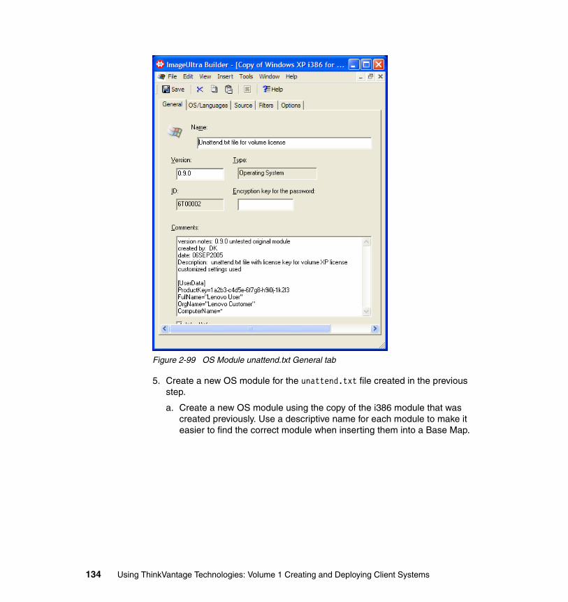
Figure 2-99 OS Module unattend.txt General tab
5. Create a new OS module for the unattend.txt file created in the previous step.
a. Create a new OS module using the copy of the i386 module that was created previously. Use a descriptive name for each module to make it easier to find the correct module when inserting them into a Base Map.
134 Using ThinkVantage Technologies: Volume 1 Creating and Deploying Client Systems
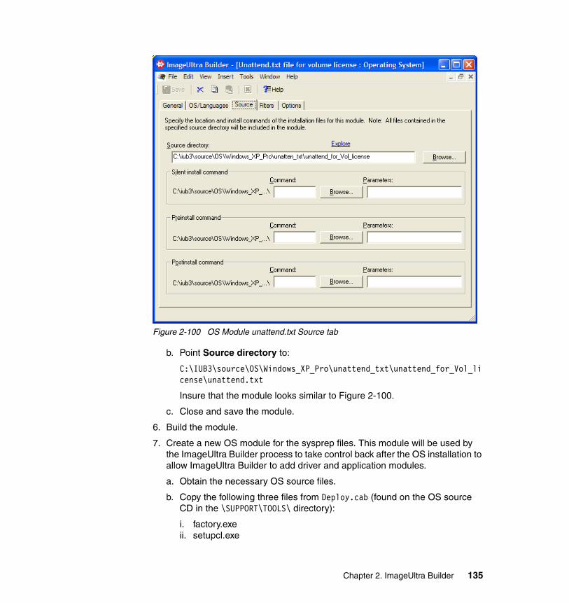
Figure 2-100 OS Module unattend.txt Source tab
b. Point Source directory to:
C:\IUB3\source\OS\Windows_XP_Pro\unattend_txt\unattend_for_Vol_license\unattend.txt
Insure that the module looks similar to Figure 2-100.
c. Close and save the module.
6. Build the module.
7. Create a new OS module for the sysprep files. This module will be used by the ImageUltra Builder process to take control back after the OS installation to allow ImageUltra Builder to add driver and application modules.
a. Obtain the necessary OS source files.
b. Copy the following three files from Deploy.cab (found on the OS source CD in the \SUPPORT\TOOLS\ directory):
i. factory.exeii. setupcl.exe
Chapter 2. ImageUltra Builder 135
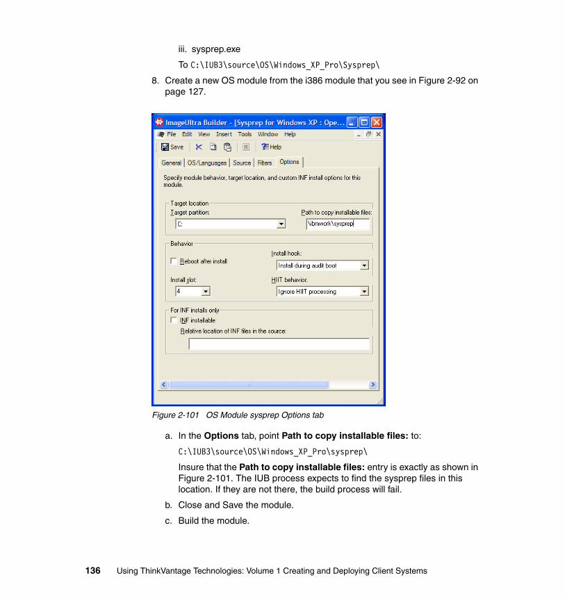
iii. sysprep.exe
To C:\IUB3\source\OS\Windows_XP_Pro\Sysprep\
8. Create a new OS module from the i386 module that you see in Figure 2-92 on page 127.
Figure 2-101 OS Module sysprep Options tab
a. In the Options tab, point Path to copy installable files: to:
C:\IUB3\source\OS\Windows_XP_Pro\sysprep\
Insure that the Path to copy installable files: entry is exactly as shown in Figure 2-101. The IUB process expects to find the sysprep files in this location. If they are not there, the build process will fail.
b. Close and Save the module.
c. Build the module.
136 Using ThinkVantage Technologies: Volume 1 Creating and Deploying Client Systems
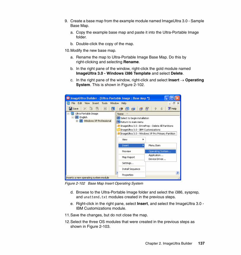
9. Create a base map from the example module named ImageUltra 3.0 - Sample Base Map.
a. Copy the example base map and paste it into the Ultra-Portable Image folder.
b. Double-click the copy of the map.
10.Modify the new base map.
a. Rename the map to Ultra-Portable Image Base Map. Do this by right-clicking and selecting Rename.
b. In the right pane of the window, right-click the gold module named ImageUltra 3.0 - Windows i386 Template and select Delete.
c. In the right pane of the window, right-click and select Insert → Operating System. This is shown in Figure 2-102.
Figure 2-102 Base Map Insert Operating System
d. Browse to the Ultra-Portable Image folder and select the i386, sysprep, and unattend.txt modules created in the previous steps.
e. Right-click in the right pane, select Insert, and select the ImageUltra 3.0 - IBM Customizations module.
11.Save the changes, but do not close the map.
12.Select the three OS modules that were created in the previous steps as shown in Figure 2-103.
Chapter 2. ImageUltra Builder 137
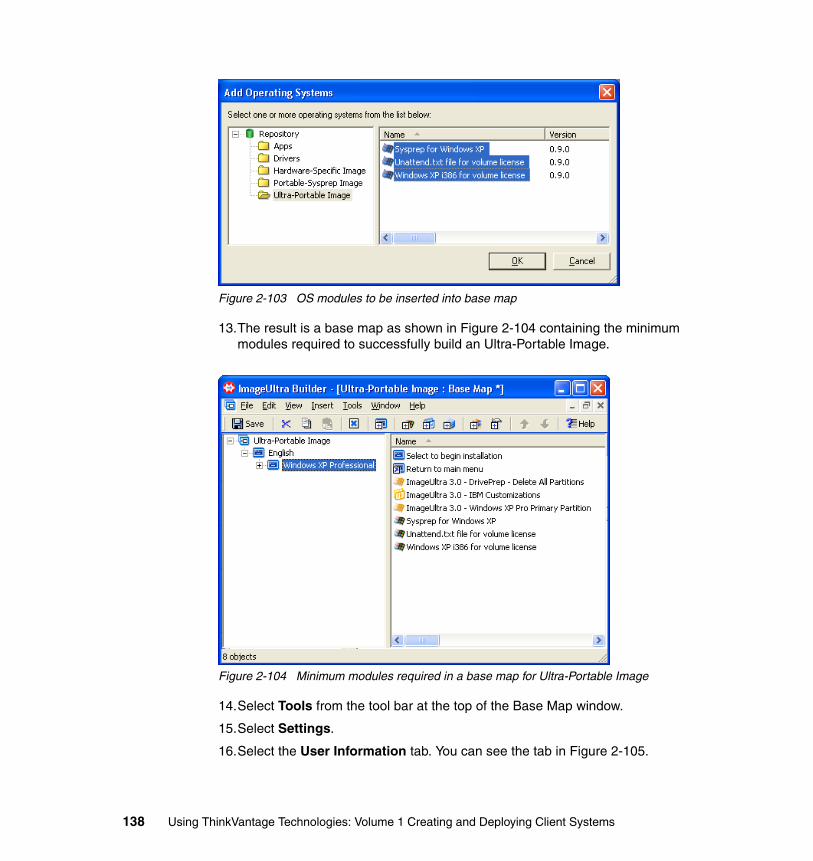
Figure 2-103 OS modules to be inserted into base map
13.The result is a base map as shown in Figure 2-104 containing the minimum modules required to successfully build an Ultra-Portable Image.
Figure 2-104 Minimum modules required in a base map for Ultra-Portable Image
14.Select Tools from the tool bar at the top of the Base Map window.
15.Select Settings.
16.Select the User Information tab. You can see the tab in Figure 2-105.
138 Using ThinkVantage Technologies: Volume 1 Creating and Deploying Client Systems
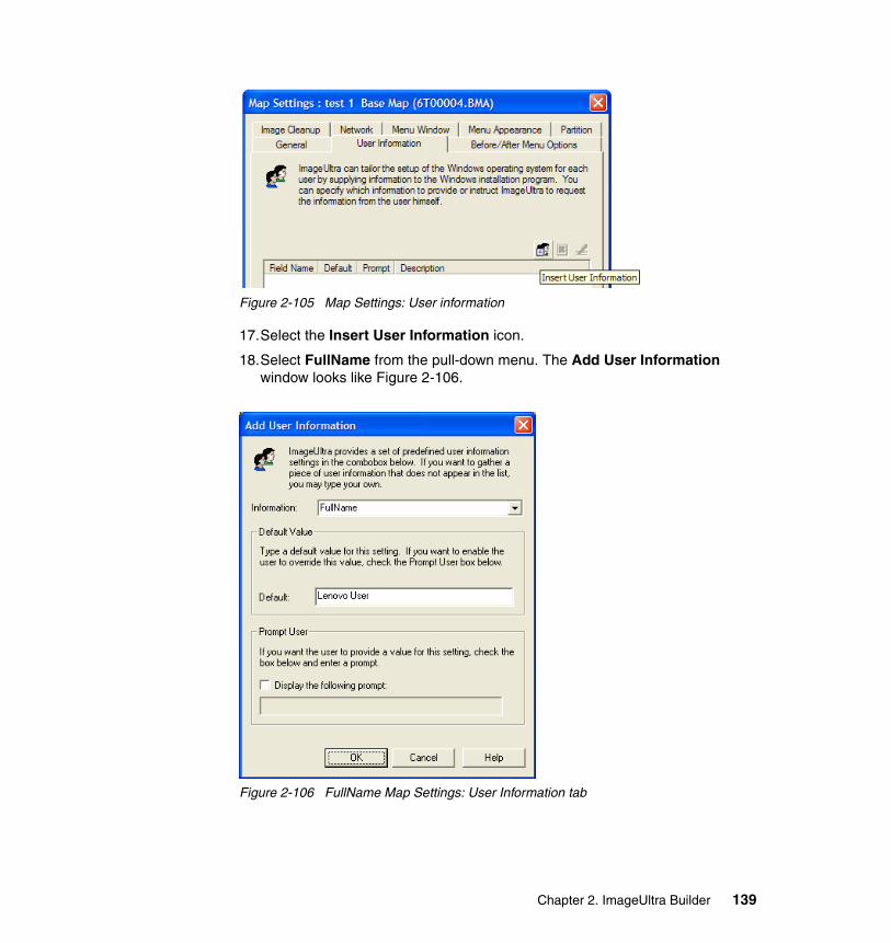
Figure 2-105 Map Settings: User information
17.Select the Insert User Information icon.
18.Select FullName from the pull-down menu. The Add User Information window looks like Figure 2-106.
Figure 2-106 FullName Map Settings: User Information tab
Chapter 2. ImageUltra Builder 139
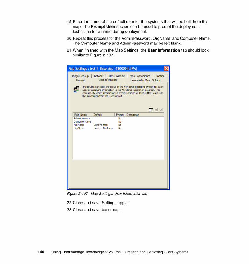
19.Enter the name of the default user for the systems that will be built from this map. The Prompt User section can be used to prompt the deployment technician for a name during deployment.
20.Repeat this process for the AdminPassword, OrgName, and Computer Name. The Computer Name and AdminPassword may be left blank.
21.When finished with the Map Settings, the User Information tab should look similar to Figure 2-107.
Figure 2-107 Map Settings: User Information tab
22.Close and save Settings applet.
23.Close and save base map.
140 Using ThinkVantage Technologies: Volume 1 Creating and Deploying Client Systems
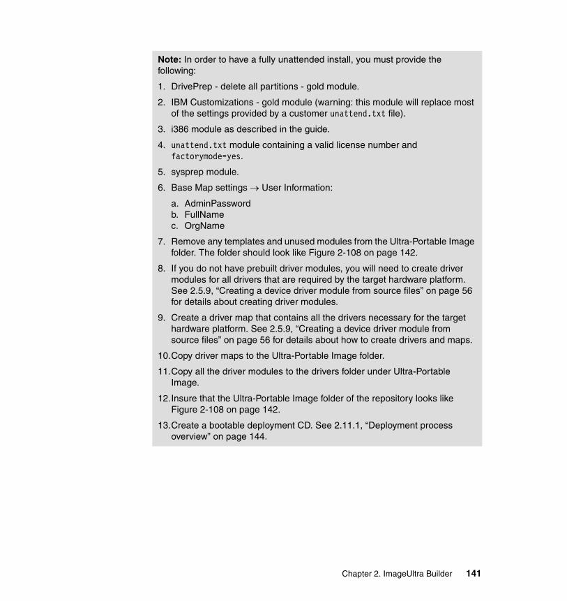
Note: In order to have a fully unattended install, you must provide the following:
1. DrivePrep - delete all partitions - gold module.
2. IBM Customizations - gold module (warning: this module will replace most of the settings provided by a customer unattend.txt file).
3. i386 module as described in the guide.
4. unattend.txt module containing a valid license number and factorymode=yes.
5. sysprep module.
6. Base Map settings → User Information:
a. AdminPasswordb. FullNamec. OrgName
7. Remove any templates and unused modules from the Ultra-Portable Image folder. The folder should look like Figure 2-108 on page 142.
8. If you do not have prebuilt driver modules, you will need to create driver modules for all drivers that are required by the target hardware platform. See 2.5.9, “Creating a device driver module from source files” on page 56 for details about creating driver modules.
9. Create a driver map that contains all the drivers necessary for the target hardware platform. See 2.5.9, “Creating a device driver module from source files” on page 56 for details about how to create drivers and maps.
10.Copy driver maps to the Ultra-Portable Image folder.
11.Copy all the driver modules to the drivers folder under Ultra-Portable Image.
12.Insure that the Ultra-Portable Image folder of the repository looks like Figure 2-108 on page 142.
13.Create a bootable deployment CD. See 2.11.1, “Deployment process overview” on page 144.
Chapter 2. ImageUltra Builder 141
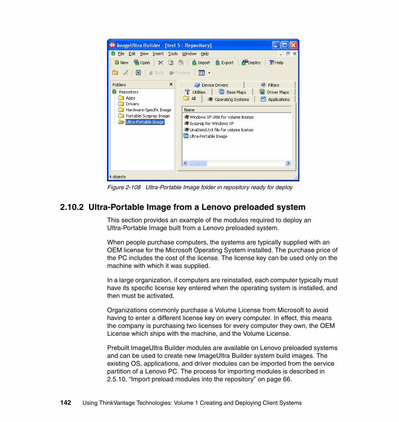
Figure 2-108 Ultra-Portable Image folder in repository ready for deploy
2.10.2 Ultra-Portable Image from a Lenovo preloaded systemThis section provides an example of the modules required to deploy an Ultra-Portable Image built from a Lenovo preloaded system.
When people purchase computers, the systems are typically supplied with an OEM license for the Microsoft Operating System installed. The purchase price of the PC includes the cost of the license. The license key can be used only on the machine with which it was supplied.
In a large organization, if computers are reinstalled, each computer typically must have its specific license key entered when the operating system is installed, and then must be activated.
Organizations commonly purchase a Volume License from Microsoft to avoid having to enter a different license key on every computer. In effect, this means the company is purchasing two licenses for every computer they own, the OEM License which ships with the machine, and the Volume License.
Prebuilt ImageUltra Builder modules are available on Lenovo preloaded systems and can be used to create new ImageUltra Builder system build images. The existing OS, applications, and driver modules can be imported from the service partition of a Lenovo PC. The process for importing modules is described in 2.5.10, “Import preload modules into the repository” on page 66.
142 Using ThinkVantage Technologies: Volume 1 Creating and Deploying Client Systems
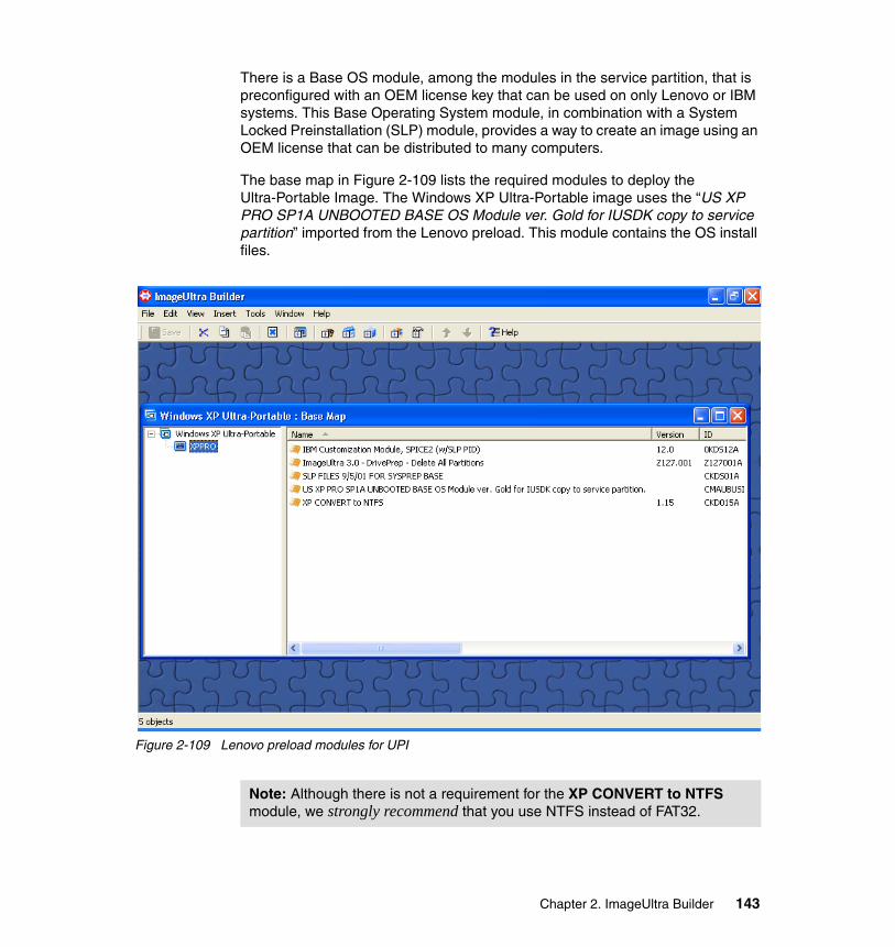
There is a Base OS module, among the modules in the service partition, that is preconfigured with an OEM license key that can be used on only Lenovo or IBM systems. This Base Operating System module, in combination with a System Locked Preinstallation (SLP) module, provides a way to create an image using an OEM license that can be distributed to many computers.
The base map in Figure 2-109 lists the required modules to deploy the Ultra-Portable Image. The Windows XP Ultra-Portable image uses the “US XP PRO SP1A UNBOOTED BASE OS Module ver. Gold for IUSDK copy to service partition” imported from the Lenovo preload. This module contains the OS install files.
Figure 2-109 Lenovo preload modules for UPI
Note: Although there is not a requirement for the XP CONVERT to NTFS module, we strongly recommend that you use NTFS instead of FAT32.
Chapter 2. ImageUltra Builder 143
2.11 Deploy and install with ImageUltra Builder
Once an image has been created using ImageUltra Builder, it is time to consider how the image is to be deployed and installed.
While there are a wide variety of image deployment methods, they fall into two fundamental categories:
� Offline deployment (requiring no network connection)� Network deployment
Natively, ImageUltra Builder’s Deploy Wizard supports offline deployment using CD-ROM or DVD media and network deployment from a Microsoft Network Share (either over NetBeui or TCP/IP). In both cases, a CD-ROM is required for the initial boot of the computer.
In Appendix A, “Smart Image deployment using third party tools” on page 373, we explore the use of other deployment options using third party cloning tools and Microsoft Remote Installation Services (RIS).
It is important that the appropriate deployment method be chosen for each situation. This section will detail a number of deployment options and suggest situations for their use.
2.11.1 Deployment process overviewFigure 2-110 provides an overview of the deploy and install phases of an ImageUltra Builder install.
Note: In the context of ImageUltra Builder, deploy is the process of copying selected maps and modules from the repository to the target computer’s service partition in preparation for installation. Install is the process of installing the operating system using the maps and modules from the service partition. See 2.11.1, “Deployment process overview” on page 144.
144 Using ThinkVantage Technologies: Volume 1 Creating and Deploying Client Systems
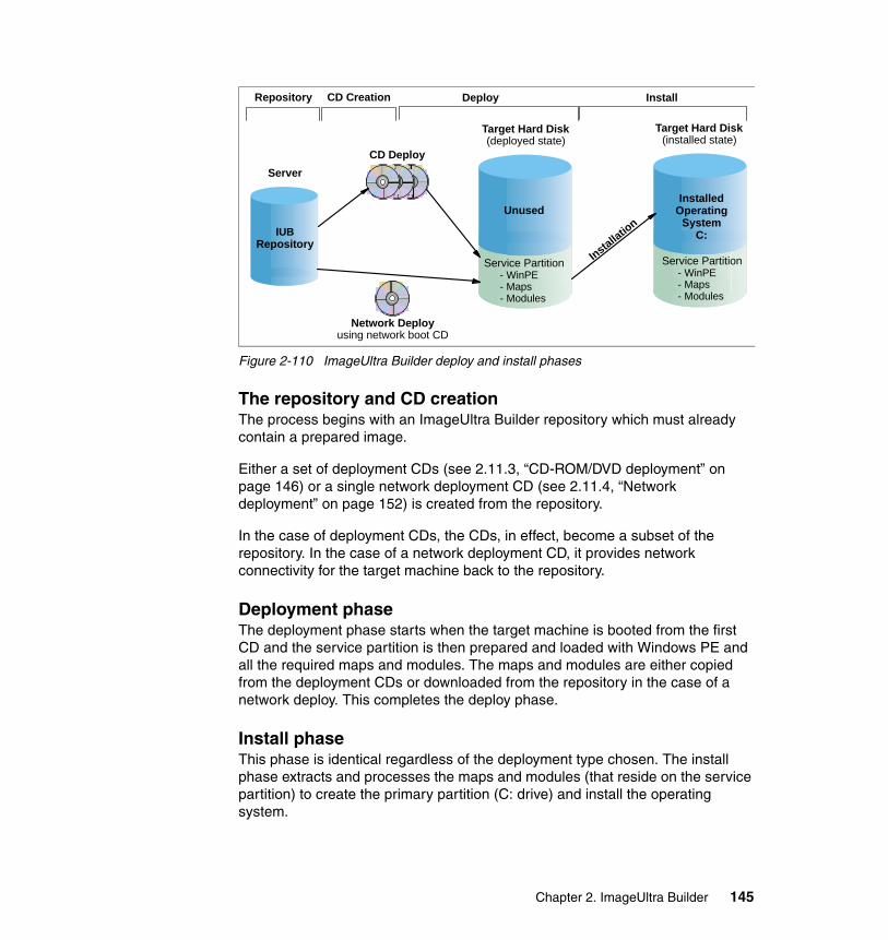
Figure 2-110 ImageUltra Builder deploy and install phases
The repository and CD creationThe process begins with an ImageUltra Builder repository which must already contain a prepared image.
Either a set of deployment CDs (see 2.11.3, “CD-ROM/DVD deployment” on page 146) or a single network deployment CD (see 2.11.4, “Network deployment” on page 152) is created from the repository.
In the case of deployment CDs, the CDs, in effect, become a subset of the repository. In the case of a network deployment CD, it provides network connectivity for the target machine back to the repository.
Deployment phaseThe deployment phase starts when the target machine is booted from the first CD and the service partition is then prepared and loaded with Windows PE and all the required maps and modules. The maps and modules are either copied from the deployment CDs or downloaded from the repository in the case of a network deploy. This completes the deploy phase.
Install phaseThis phase is identical regardless of the deployment type chosen. The install phase extracts and processes the maps and modules (that reside on the service partition) to create the primary partition (C: drive) and install the operating system.
IUBRepository
CD Deploy
Target Hard Disk(deployed state)
Target Hard Disk(installed state)
Unused
Service Partition- WinPE- Maps- Modules
InstalledOperating
SystemC:
Service Partition- WinPE- Maps- Modules
Network Deployusing network boot CD
Server
Installation
Repository Deploy InstallCD Creation
Chapter 2. ImageUltra Builder 145
2.11.2 The deployment environment (Windows PE)The deployment environment has changed significantly in ImageUltra Builder 3.0. In previous versions, all deployments were initiated via DOS (usually a DOS boot disk). In ImageUltra Builder 3.0, the DOS environment has been replaced by Microsoft Windows PE (Preinstallation Environment). Windows PE is a 32-bit Windows environment which can be booted and run from removable media, such as a CD-ROM and requires no files to be installed on the computer’s local hard disk.
The benefits that Windows PE provides include:
� Support for Windows XP drivers (including network and hard disk)
� Improved performance for network and hard disk through the use of 32-bit drivers which support more advanced features of the hardware
� The ability to run simple 32-bit applications
� The ability to create menus using the standard Windows interface
� Ability to create and format NTFS partitions with none of the DOS partition size limitations
Windows PE can take significantly longer to boot than a DOS diskette, but this is outweighed by its flexibility and many other benefits.
2.11.3 CD-ROM/DVD deploymentCD-ROM or DVD deployment methods are ideal for situations where machines cannot be connected to a network. CD-ROM installs usually require more user interaction because CDs have to be swapped (less so with DVDs), but no additional infrastructure is required making it the practical choice for many small scale situations.
CD-ROM or DVD deployment is not recommended for situations where large numbers of machines need to be rebuilt. CD-ROM or DVD deployment would be better suited for use by technicians and support staff who travel to remote sites and perform one-off installs or rebuilds in situations where using a network deployment is impractical.
CD-ROM or DVD-based deployments are not suited to situations where the image content changes frequently. Each time there are updates to an image, the CD-ROM or DVD set will need to be recreated, rendering the previous set obsolete. Not having a network connection also means that you cannot take advantage of the network sync process (see Network Sync definition in 2.3.1, “ImageUltra Builder terminology” on page 21).
146 Using ThinkVantage Technologies: Volume 1 Creating and Deploying Client Systems
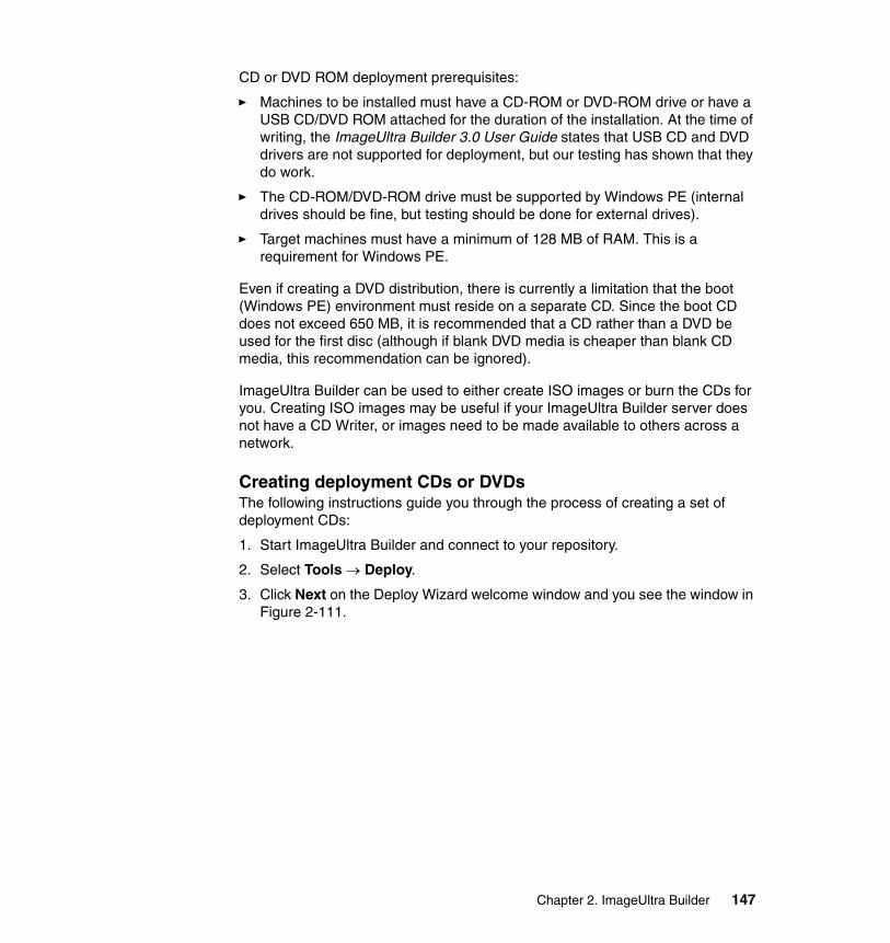
CD or DVD ROM deployment prerequisites:
� Machines to be installed must have a CD-ROM or DVD-ROM drive or have a USB CD/DVD ROM attached for the duration of the installation. At the time of writing, the ImageUltra Builder 3.0 User Guide states that USB CD and DVD drivers are not supported for deployment, but our testing has shown that they do work.
� The CD-ROM/DVD-ROM drive must be supported by Windows PE (internal drives should be fine, but testing should be done for external drives).
� Target machines must have a minimum of 128 MB of RAM. This is a requirement for Windows PE.
Even if creating a DVD distribution, there is currently a limitation that the boot (Windows PE) environment must reside on a separate CD. Since the boot CD does not exceed 650 MB, it is recommended that a CD rather than a DVD be used for the first disc (although if blank DVD media is cheaper than blank CD media, this recommendation can be ignored).
ImageUltra Builder can be used to either create ISO images or burn the CDs for you. Creating ISO images may be useful if your ImageUltra Builder server does not have a CD Writer, or images need to be made available to others across a network.
Creating deployment CDs or DVDsThe following instructions guide you through the process of creating a set of deployment CDs:
1. Start ImageUltra Builder and connect to your repository.
2. Select Tools → Deploy.
3. Click Next on the Deploy Wizard welcome window and you see the window in Figure 2-111.
Chapter 2. ImageUltra Builder 147
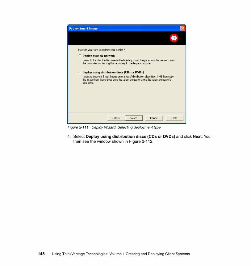
Figure 2-111 Deploy Wizard: Selecting deployment type
4. Select Deploy using distribution discs (CDs or DVDs) and click Next. You l then see the window shown in Figure 2-112.
148 Using ThinkVantage Technologies: Volume 1 Creating and Deploying Client Systems
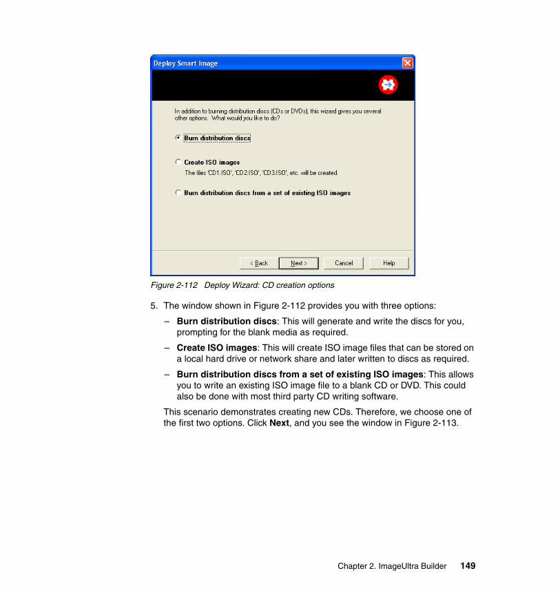
Figure 2-112 Deploy Wizard: CD creation options
5. The window shown in Figure 2-112 provides you with three options:
– Burn distribution discs: This will generate and write the discs for you, prompting for the blank media as required.
– Create ISO images: This will create ISO image files that can be stored on a local hard drive or network share and later written to discs as required.
– Burn distribution discs from a set of existing ISO images: This allows you to write an existing ISO image file to a blank CD or DVD. This could also be done with most third party CD writing software.
This scenario demonstrates creating new CDs. Therefore, we choose one of the first two options. Click Next, and you see the window in Figure 2-113.
Chapter 2. ImageUltra Builder 149
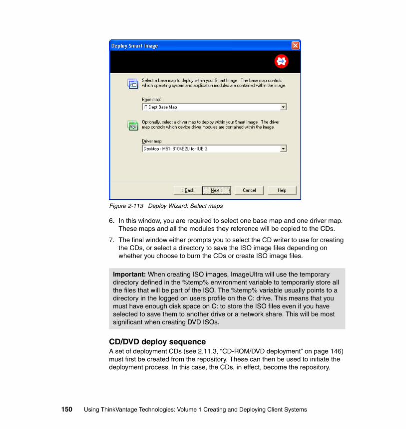
Figure 2-113 Deploy Wizard: Select maps
6. In this window, you are required to select one base map and one driver map. These maps and all the modules they reference will be copied to the CDs.
7. The final window either prompts you to select the CD writer to use for creating the CDs, or select a directory to save the ISO image files depending on whether you choose to burn the CDs or create ISO image files.
CD/DVD deploy sequenceA set of deployment CDs (see 2.11.3, “CD-ROM/DVD deployment” on page 146) must first be created from the repository. These can then be used to initiate the deployment process. In this case, the CDs, in effect, become the repository.
Important: When creating ISO images, ImageUltra will use the temporary directory defined in the %temp% environment variable to temporarily store all the files that will be part of the ISO. The %temp% variable usually points to a directory in the logged on users profile on the C: drive. This means that you must have enough disk space on C: to store the ISO files even if you have selected to save them to another drive or a network share. This will be most significant when creating DVD ISOs.
150 Using ThinkVantage Technologies: Volume 1 Creating and Deploying Client Systems

The process then follows these steps:
1. The process is started by booting the target computer from the first CD. This can be done by temporarily changing the computer’s boot sequence (using the F12 key on IBM hardware), or by changing the boot sequence in the BIOS and placing the CD-ROM before the internal hard disk drive.
2. When the computer starts to boot from the CD, a message prompts you to
Press any key to boot from CD.
A key must be pressed within 5 seconds to initiate the CD boot and begin the deployment process; otherwise, the computer will boot from the hard disk.
3. The boot environment will start and the ImageUltra Deploy Center Wizard window will appear.
4. Click Next and a window will appear showing the name of the base map that will be installed. At the bottom of this window, there is a check box entitled Create new SP. Checking this box will cause an existing service partition to be deleted, and a new one created. Leaving this box unchecked will cause the build to use the existing service partition, which will be resized and cleaned as required. If no service partition is present on the computer, this check box has no effect.
5. Click Finish.
6. The deployment process now prepares the service partition and copies all the required modules to the service partition. Once this is done, the deployment process is complete (see 2.11.1, “Deployment process overview” on page 144), and a prompt will appear warning you not to remove the CD until the machine has powered off. Unfortunately, it is a little difficult to remove the CD after the machine has powered off and we do not recommend using a paper clip to force open the CD drive. Once the machine has powered off, power it on again and quickly remove the CD. If the machine is to be left in the deployed but not installed state, then quickly turn the machine off again before it begins to boot.
Proceed to section 2.11.5, “Install phase” on page 162 for details about the installation phase.
Note: At this point, the machine has completed the deployment phase. This means that all the files required for the install are now located on the service partition. The machine can either be rebooted immediately to continue the install, or shipped to another location where the install will be performed.
Chapter 2. ImageUltra Builder 151
2.11.4 Network deploymentNetwork deployments are recommended for lab or store room environments where many machines need to be built concurrently, or for one-off rebuilds of machines attached to robust networks and in proximity to the ImageUltra Builder server.
Network builds still require a CD or DVD ROM to boot Windows PE to establish a network connection. Once connected, the installation can proceed with less user interaction than with CDs, and the same installation source can be used over the network by many machines simultaneously. The number of machines that can be done at one time is limited by the network speed, and the capacity of the Image Ultra Builder server.
Prerequisites:
� Machines to be installed must have a CD-ROM or DVD-ROM drive or have a USB CD/DVD ROM attached for the duration of the installation.
� The CD-ROM or DVD-ROM drive must be supported by Windows PE (internal drives should be fine, but testing should be done for external drives).
� Machines must have a minimum of 128 MB of RAM. This is the minimum amount of RAM required to run Windows PE from a CD-ROM.
� Machines must have a network card that is supported by Windows PE. See “Adding network device drivers to Windows PE” on page 172 for details about adding network drivers to Windows PE.
� An ImageUltra Builder server must be attached to the same network as the machine to be built.
Creating a network deployment CDThe following steps describe how to create a network deployment CD:
1. Start ImageUltra Builder.
2. Connect to your repository.
3. Select Tools → Deploy.
4. Click Next on the Deploy Wizard welcome window and you see the window in Figure 2-114.
152 Using ThinkVantage Technologies: Volume 1 Creating and Deploying Client Systems
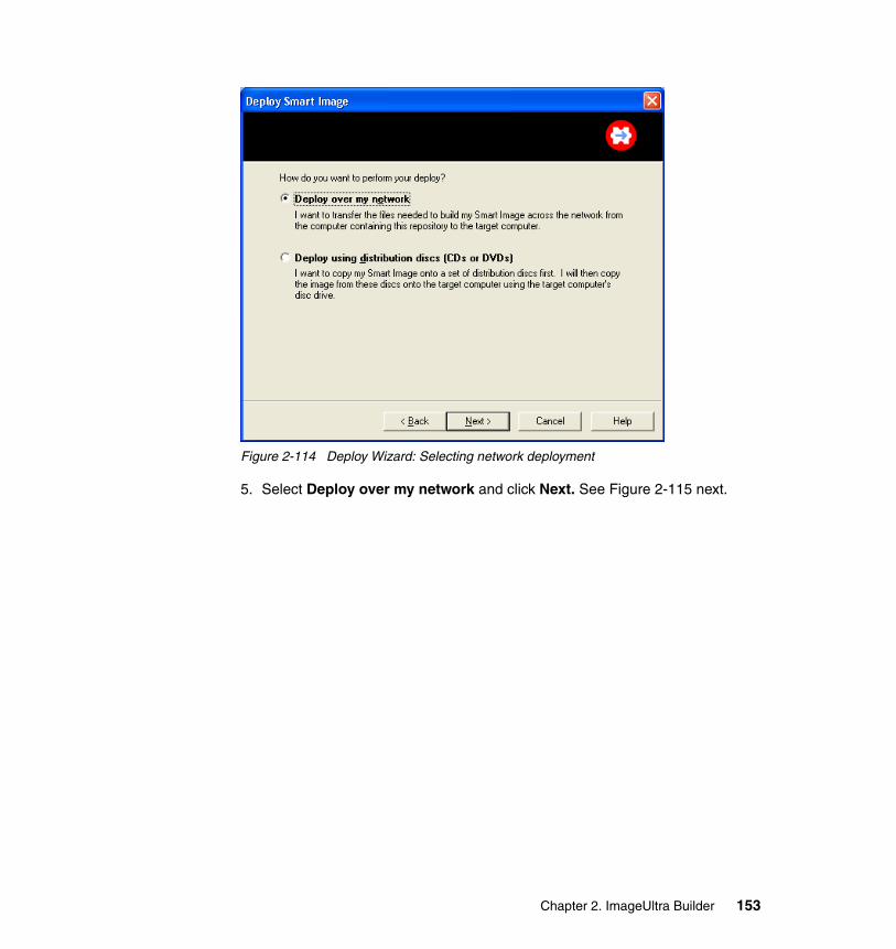
Figure 2-114 Deploy Wizard: Selecting network deployment
5. Select Deploy over my network and click Next. See Figure 2-115 next.
Chapter 2. ImageUltra Builder 153
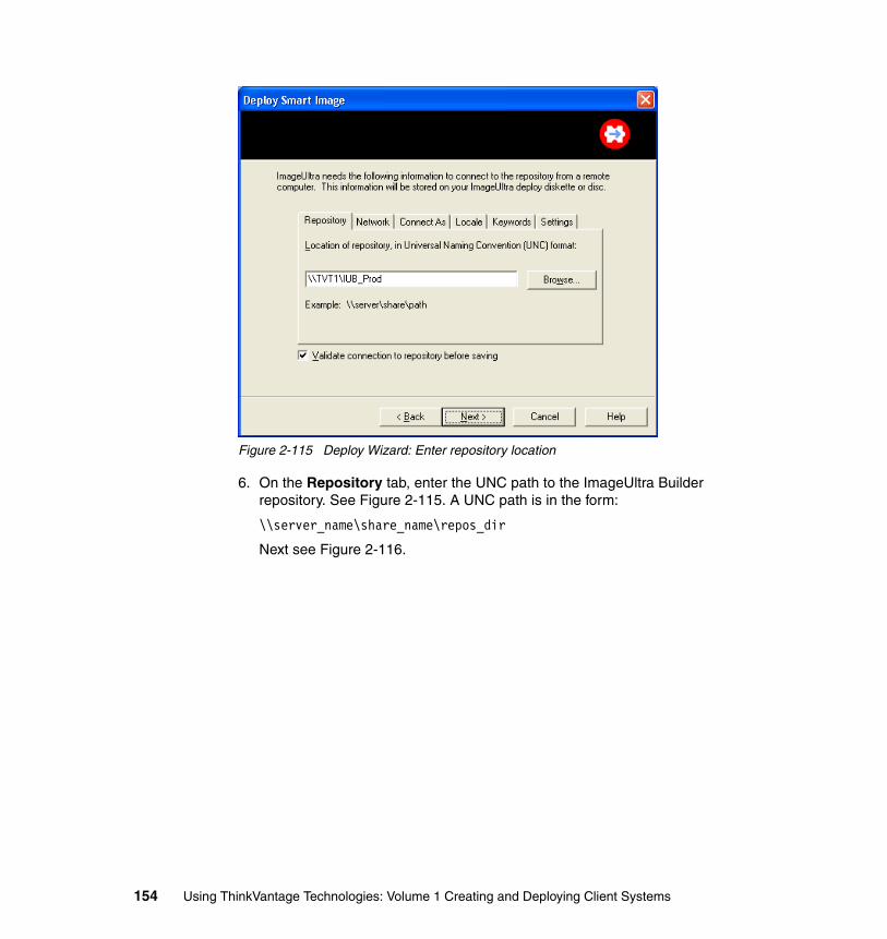
Figure 2-115 Deploy Wizard: Enter repository location
6. On the Repository tab, enter the UNC path to the ImageUltra Builder repository. See Figure 2-115. A UNC path is in the form:
\\server_name\share_name\repos_dir
Next see Figure 2-116.
154 Using ThinkVantage Technologies: Volume 1 Creating and Deploying Client Systems
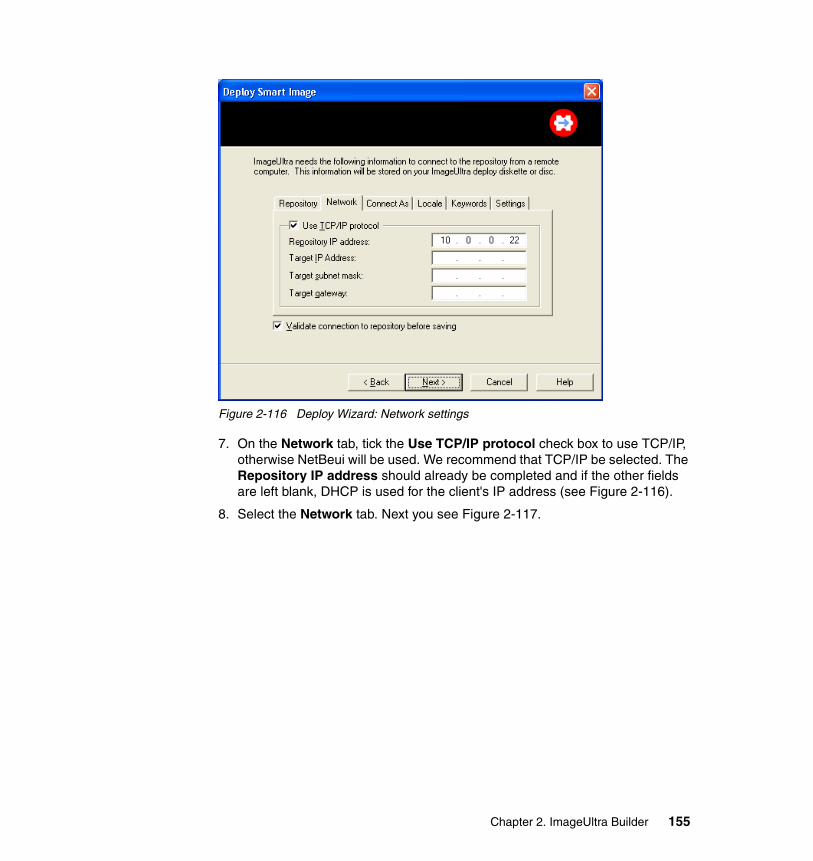
Figure 2-116 Deploy Wizard: Network settings
7. On the Network tab, tick the Use TCP/IP protocol check box to use TCP/IP, otherwise NetBeui will be used. We recommend that TCP/IP be selected. The Repository IP address should already be completed and if the other fields are left blank, DHCP is used for the client's IP address (see Figure 2-116).
8. Select the Network tab. Next you see Figure 2-117.
Chapter 2. ImageUltra Builder 155
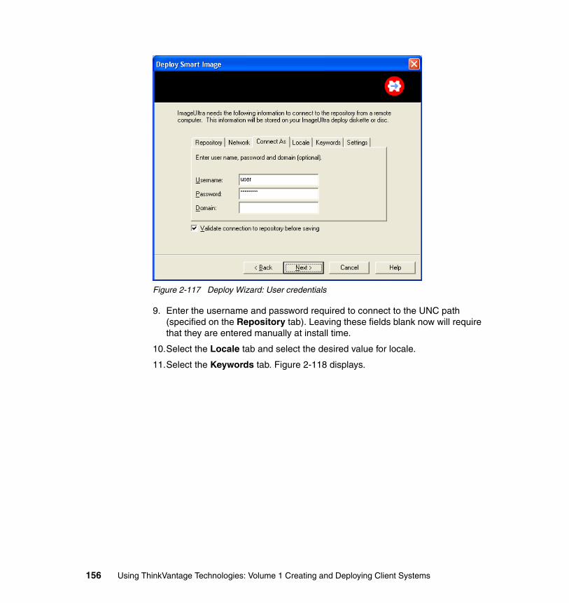
Figure 2-117 Deploy Wizard: User credentials
9. Enter the username and password required to connect to the UNC path (specified on the Repository tab). Leaving these fields blank now will require that they are entered manually at install time.
10.Select the Locale tab and select the desired value for locale.
11.Select the Keywords tab. Figure 2-118 displays.
156 Using ThinkVantage Technologies: Volume 1 Creating and Deploying Client Systems
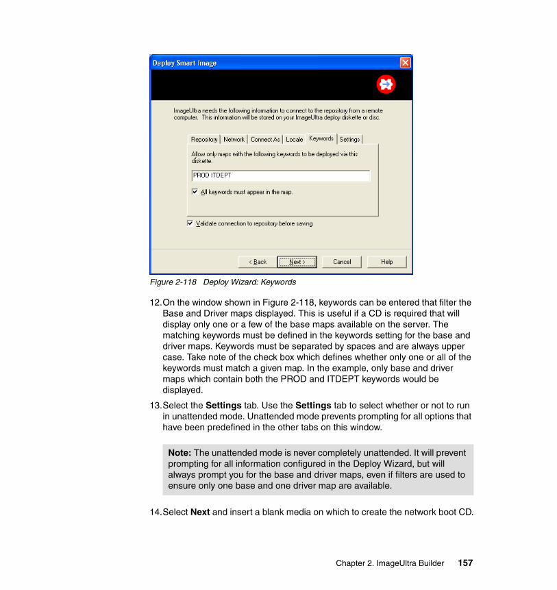
Figure 2-118 Deploy Wizard: Keywords
12.On the window shown in Figure 2-118, keywords can be entered that filter the Base and Driver maps displayed. This is useful if a CD is required that will display only one or a few of the base maps available on the server. The matching keywords must be defined in the keywords setting for the base and driver maps. Keywords must be separated by spaces and are always upper case. Take note of the check box which defines whether only one or all of the keywords must match a given map. In the example, only base and driver maps which contain both the PROD and ITDEPT keywords would be displayed.
13.Select the Settings tab. Use the Settings tab to select whether or not to run in unattended mode. Unattended mode prevents prompting for all options that have been predefined in the other tabs on this window.
14.Select Next and insert a blank media on which to create the network boot CD.
Note: The unattended mode is never completely unattended. It will prevent prompting for all information configured in the Deploy Wizard, but will always prompt you for the base and driver maps, even if filters are used to ensure only one base and one driver map are available.
Chapter 2. ImageUltra Builder 157
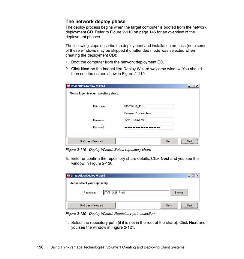
The network deploy phaseThe deploy process begins when the target computer is booted from the network deployment CD. Refer to Figure 2-110 on page 145 for an overview of the deployment phases.
The following steps describe the deployment and installation process (note some of these windows may be skipped if unattended mode was selected when creating the deployment CD):
1. Boot the computer from the network deployment CD.
2. Click Next on the ImageUltra Deploy Wizard welcome window. You should then see the screen show in Figure 2-119.
Figure 2-119 Deploy Wizard: Select repository share
3. Enter or confirm the repository share details. Click Next and you see the window in Figure 2-120.
Figure 2-120 Deploy Wizard: Repository path selection
4. Select the repository path (if it is not in the root of the share). Click Next and you see the window in Figure 2-121.
158 Using ThinkVantage Technologies: Volume 1 Creating and Deploying Client Systems
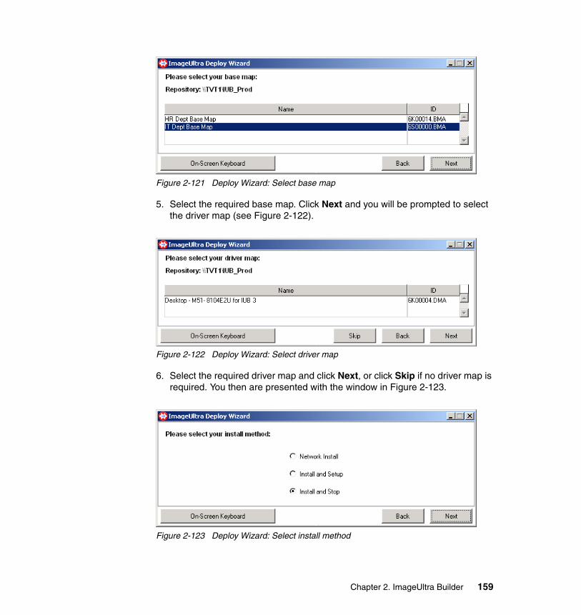
Figure 2-121 Deploy Wizard: Select base map
5. Select the required base map. Click Next and you will be prompted to select the driver map (see Figure 2-122).
Figure 2-122 Deploy Wizard: Select driver map
6. Select the required driver map and click Next, or click Skip if no driver map is required. You then are presented with the window in Figure 2-123.
Figure 2-123 Deploy Wizard: Select install method
Chapter 2. ImageUltra Builder 159
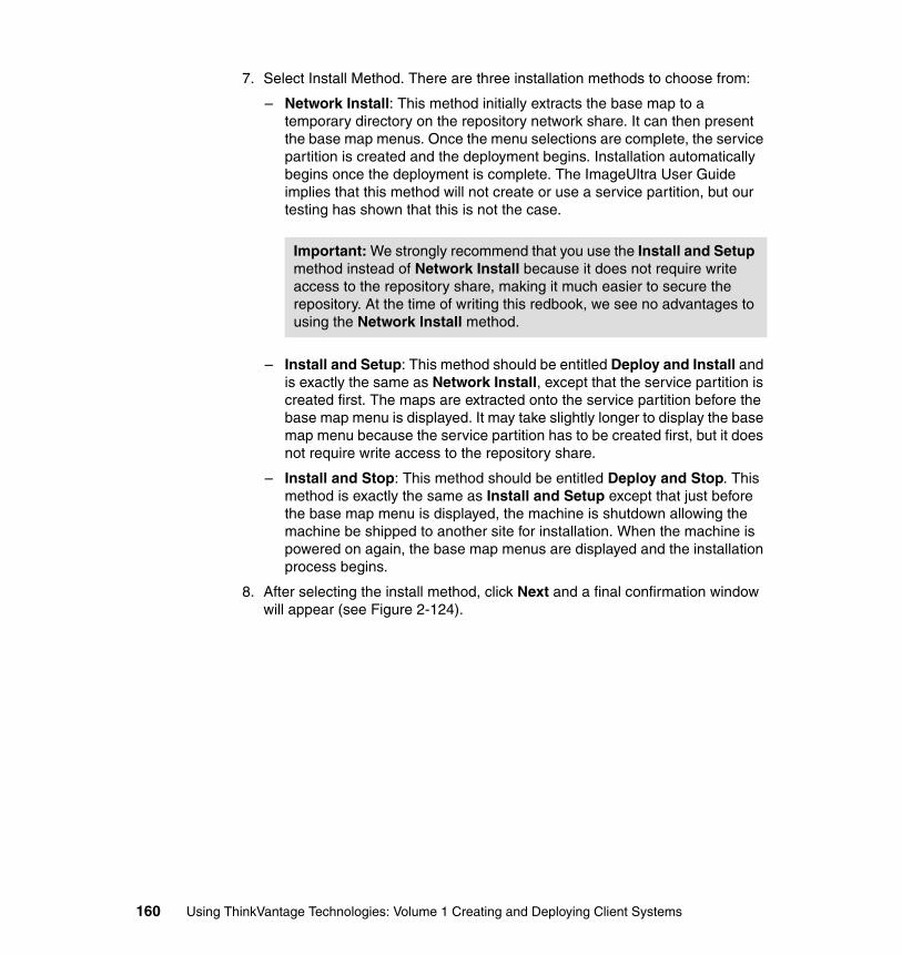
7. Select Install Method. There are three installation methods to choose from:
– Network Install: This method initially extracts the base map to a temporary directory on the repository network share. It can then present the base map menus. Once the menu selections are complete, the service partition is created and the deployment begins. Installation automatically begins once the deployment is complete. The ImageUltra User Guide implies that this method will not create or use a service partition, but our testing has shown that this is not the case.
– Install and Setup: This method should be entitled Deploy and Install and is exactly the same as Network Install, except that the service partition is created first. The maps are extracted onto the service partition before the base map menu is displayed. It may take slightly longer to display the base map menu because the service partition has to be created first, but it does not require write access to the repository share.
– Install and Stop: This method should be entitled Deploy and Stop. This method is exactly the same as Install and Setup except that just before the base map menu is displayed, the machine is shutdown allowing the machine be shipped to another site for installation. When the machine is powered on again, the base map menus are displayed and the installation process begins.
8. After selecting the install method, click Next and a final confirmation window will appear (see Figure 2-124).
Important: We strongly recommend that you use the Install and Setup method instead of Network Install because it does not require write access to the repository share, making it much easier to secure the repository. At the time of writing this redbook, we see no advantages to using the Network Install method.
160 Using ThinkVantage Technologies: Volume 1 Creating and Deploying Client Systems
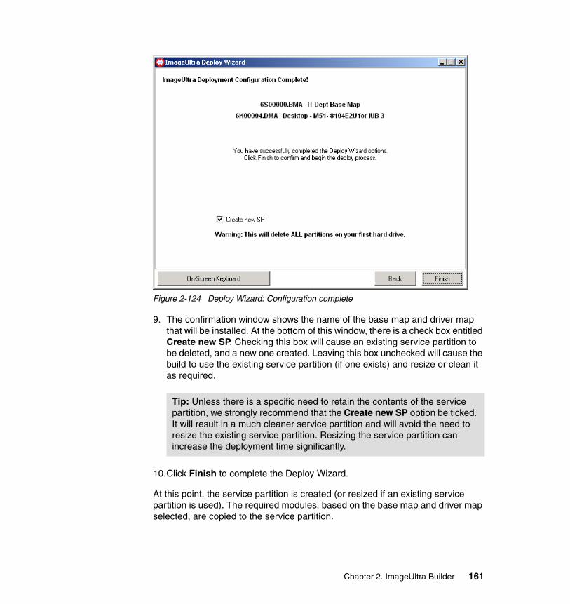
Figure 2-124 Deploy Wizard: Configuration complete
9. The confirmation window shows the name of the base map and driver map that will be installed. At the bottom of this window, there is a check box entitled Create new SP. Checking this box will cause an existing service partition to be deleted, and a new one created. Leaving this box unchecked will cause the build to use the existing service partition (if one exists) and resize or clean it as required.
10.Click Finish to complete the Deploy Wizard.
At this point, the service partition is created (or resized if an existing service partition is used). The required modules, based on the base map and driver map selected, are copied to the service partition.
Tip: Unless there is a specific need to retain the contents of the service partition, we strongly recommend that the Create new SP option be ticked. It will result in a much cleaner service partition and will avoid the need to resize the existing service partition. Resizing the service partition can increase the deployment time significantly.
Chapter 2. ImageUltra Builder 161
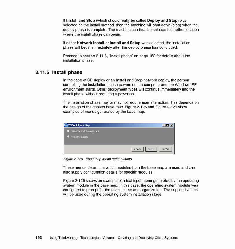
If Install and Stop (which should really be called Deploy and Stop) was selected as the install method, then the machine will shut down (stop) when the deploy phase is complete. The machine can then be shipped to another location where the install phase can begin.
If either Network Install or Install and Setup was selected, the installation phase will begin immediately after the deploy phase has concluded.
Proceed to section 2.11.5, “Install phase” on page 162 for details about the installation phase.
2.11.5 Install phaseIn the case of CD deploy or an Install and Stop network deploy, the person controlling the installation phase powers on the computer and the Windows PE environment starts. Other deployment types will continue immediately into the install phase without requiring a power on.
The installation phase may or may not require user interaction. This depends on the design of the chosen base map. Figure 2-125 and Figure 2-126 show examples of menus generated by the base map.
Figure 2-125 Base map menu radio buttons
These menus determine which modules from the base map are used and can also supply configuration details for specific modules.
Figure 2-126 shows an example of a text input menu generated by the operating system module in the base map. In this case, the operating system module was configured to prompt for the user’s name and organization. The supplied values will be used during the operating system installation stage.
162 Using ThinkVantage Technologies: Volume 1 Creating and Deploying Client Systems
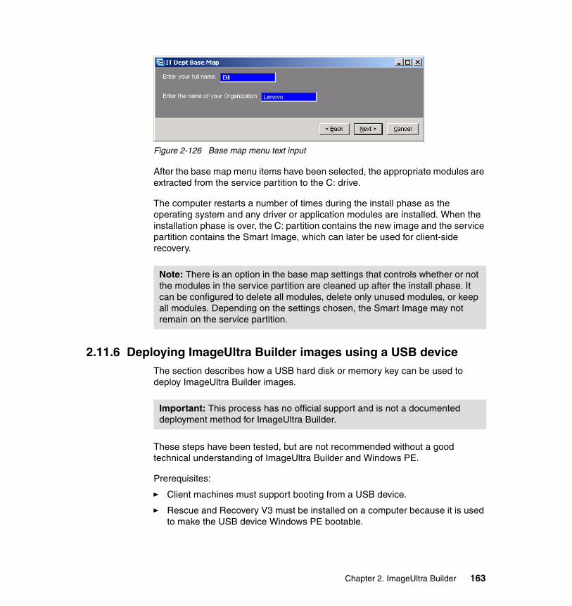
Figure 2-126 Base map menu text input
After the base map menu items have been selected, the appropriate modules are extracted from the service partition to the C: drive.
The computer restarts a number of times during the install phase as the operating system and any driver or application modules are installed. When the installation phase is over, the C: partition contains the new image and the service partition contains the Smart Image, which can later be used for client-side recovery.
2.11.6 Deploying ImageUltra Builder images using a USB deviceThe section describes how a USB hard disk or memory key can be used to deploy ImageUltra Builder images.
These steps have been tested, but are not recommended without a good technical understanding of ImageUltra Builder and Windows PE.
Prerequisites:
� Client machines must support booting from a USB device.
� Rescue and Recovery V3 must be installed on a computer because it is used to make the USB device Windows PE bootable.
Note: There is an option in the base map settings that controls whether or not the modules in the service partition are cleaned up after the install phase. It can be configured to delete all modules, delete only unused modules, or keep all modules. Depending on the settings chosen, the Smart Image may not remain on the service partition.
Important: This process has no official support and is not a documented deployment method for ImageUltra Builder.
Chapter 2. ImageUltra Builder 163
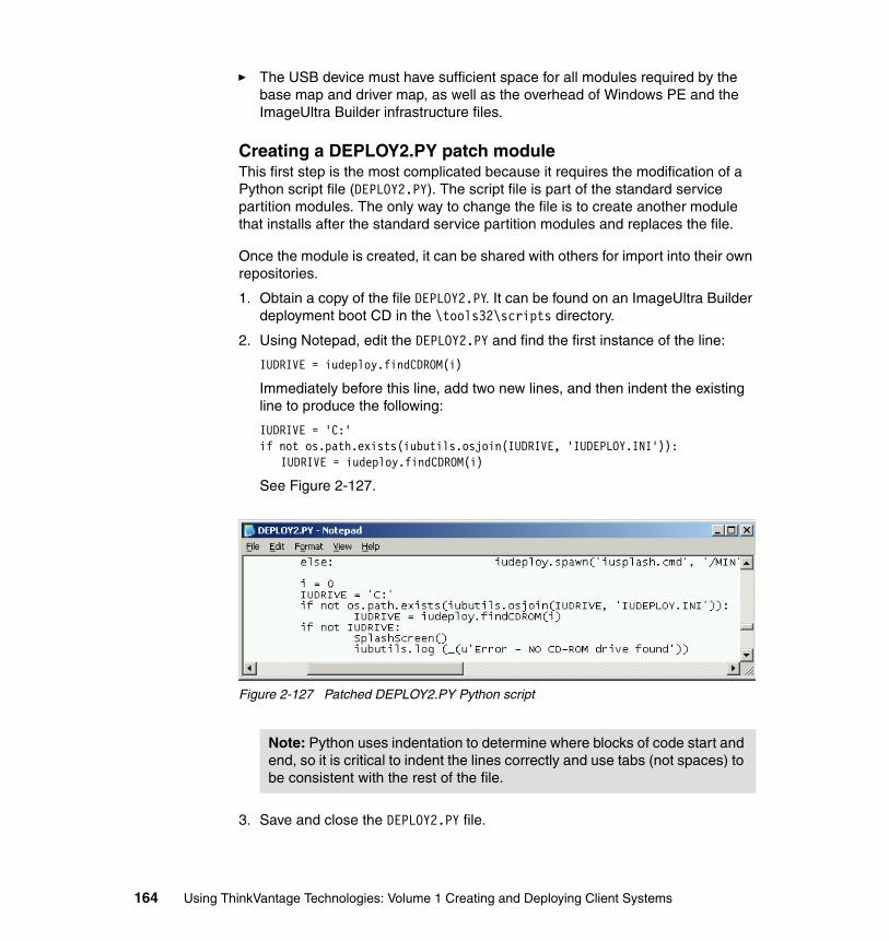
� The USB device must have sufficient space for all modules required by the base map and driver map, as well as the overhead of Windows PE and the ImageUltra Builder infrastructure files.
Creating a DEPLOY2.PY patch moduleThis first step is the most complicated because it requires the modification of a Python script file (DEPLOY2.PY). The script file is part of the standard service partition modules. The only way to change the file is to create another module that installs after the standard service partition modules and replaces the file.
Once the module is created, it can be shared with others for import into their own repositories.
1. Obtain a copy of the file DEPLOY2.PY. It can be found on an ImageUltra Builder deployment boot CD in the \tools32\scripts directory.
2. Using Notepad, edit the DEPLOY2.PY and find the first instance of the line:
IUDRIVE = iudeploy.findCDROM(i)
Immediately before this line, add two new lines, and then indent the existing line to produce the following:
IUDRIVE = 'C:'if not os.path.exists(iubutils.osjoin(IUDRIVE, 'IUDEPLOY.INI')):
IUDRIVE = iudeploy.findCDROM(i)
See Figure 2-127.
Figure 2-127 Patched DEPLOY2.PY Python script
3. Save and close the DEPLOY2.PY file.
Note: Python uses indentation to determine where blocks of code start and end, so it is critical to indent the lines correctly and use tabs (not spaces) to be consistent with the rest of the file.
164 Using ThinkVantage Technologies: Volume 1 Creating and Deploying Client Systems
The change above is the simplest change to make to make the process work, but it is not an ideal solution. It assumes that if you are using a USB CD or USB memory key that it will be assigned as C: drive (which should be the case in most situations). If it does not find the IUDEPLOY.INI file on the C: drive, it will revert to its standard CD-ROM check, which means that the patched file can be used for CD or USB deployments.
4. Create a new ImageUltra Builder OS module called DEPLOY2 USB Patch and point the source to the a directory that contains only the patched DEPLOY2.PY file. The target should be set to “Service Partition” and the target path should be \recovery\iub\tools32\scripts.
5. Add this module to your Base Map. It will overwrite the DEPLOY2.PY that is contained within one of the base modules.
Prepare the USB device1. On a computer with Rescue and Recovery 3 installed, launch the Create
Recovery Media tool.
2. Under Select rescue medium, choose USB hard disk drive.
3. Select the Target drive, and whether or not to Destroy existing data on the drive.
4. Click OK. This will install Windows PE on the USB drive and make it bootable.
5. Once the recovery media step is complete, delete the following files from the USB device:
MinintPrebootfcopy.iniformatted.tag
Rescue and Recovery was really only used to install the appropriate boot loader and make the USB device bootable.
6. Use IUB's Deploy Wizard to create a set of ISO images for CD/DVD deployment. The maps selected here will be the only ones available on the USB device. Make sure that the map chosen contains the DEPLOY2 USB patch module created previously.
7. Either burn the ISO images to CDs or use an ISO file manager to extract all the files from the ISO images.
8. From the contents of the first ImageUltra Builder CD, copy the following directories and files onto the USB device:
i386mapsmodulespreboot
Chapter 2. ImageUltra Builder 165
recoverytools32IUDEPLOY.INI
9. From the contents of all other ImageUltra Builder CDs, copy the following folders onto the USB device (some modules appear on all CDs, you can overwrite or skip when copying them):
mapsmodules
10.On the USB device, rename i386 to minint.
11.On the USB device, create a file in the root directory called iubcd.tag. Right-click the iubcd.tag file and tick the Read-only check box (this ensures one of the batch files detects the USB device as a CD).
12.Edit the IUDEPLOY.INI file, and change the TotalCDs line to TotalCDs=1.
The USB device is now ready to be used to deploy and install the Smart Image selected. Simply boot the target computer from the USB device, and install exactly as if you were installing from a set of CDs. After the deploy phase, you will receive a prompt telling you not to remove the CD until the computer has shut down. Click OK on the message, and when the machine has shut down, you can detach the USB device because it is not required for the install phase.
2.11.7 Deployment and installation troubleshootingDuring the deploy and install phases (see Figure 2-110 on page 145), ImageUltra Builder maintains a log file called stamp.log. This log file is displayed during the deploy phase and parts of the install phase by a tool called splash. Figure 2-128 shows the stamp.log file displayed by splash.
166 Using ThinkVantage Technologies: Volume 1 Creating and Deploying Client Systems
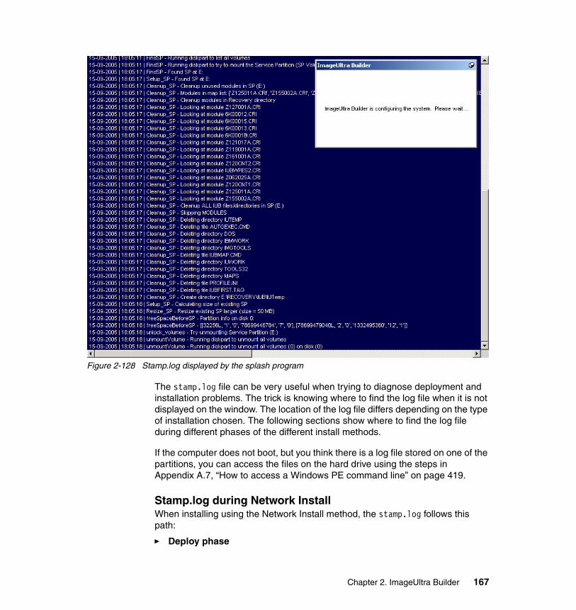
Figure 2-128 Stamp.log displayed by the splash program
The stamp.log file can be very useful when trying to diagnose deployment and installation problems. The trick is knowing where to find the log file when it is not displayed on the window. The location of the log file differs depending on the type of installation chosen. The following sections show where to find the log file during different phases of the different install methods.
If the computer does not boot, but you think there is a log file stored on one of the partitions, you can access the files on the hard drive using the steps in Appendix A.7, “How to access a Windows PE command line” on page 419.
Stamp.log during Network InstallWhen installing using the Network Install method, the stamp.log follows this path:
� Deploy phase
Chapter 2. ImageUltra Builder 167
During the deploy phase, stamp.log can be found in the repository share in the following directory (where y: is mapped to the repository share):
y:\NetDepl\{MAC}\recovery\iub\IUTemp\Stamp.log
Where {MAC} is the MAC address of the computer’s network card. The log file can be viewed on the repository server during this phase, but it is deleted as soon as the install phase begins.
� Install phase
Once the install phase begins, the stamp.log is copied onto the new C: partition (which is commonly assigned to T: within Windows PE) and can be found here:
c:\iuwork\IUTemp\Stamp.log
The very last step of the install phase moves the stamp.log file to the following directory:
c:\windows\LASTCFG\Stamp.log
Stamp.log during Install and Setup or Install and StopWhen installing using the Install and Setup or Install and Stop methods, the stamp.log follows this path:
� Deploy phase
During the deploy phase, stamp.log can be found in the root directory of the RAM drive, which is usually assigned a drive letter of Z:
z:\Stamp.log
If the computer is restarted or hangs at any point during this phase, the log file will be lost.
� Install phase
Once the install phase begins, the stamp.log is briefly copied to a different directory on the service partition:
z:\IUTemp\stamp.log
and then is copied to the service partition (W:), and the new C: drive:
W:\Recovery\iub\LASTCFG\Stamp.logC:\iuwork\IUTemp\Stamp.log
The very last step of the install phase moves the stamp.log file to the following directory:
c:\windows\LASTCFG\Stamp.log
168 Using ThinkVantage Technologies: Volume 1 Creating and Deploying Client Systems
2.11.8 Creating an ISO image of the network boot CDIn some cases, it may be useful to create an ISO image of the network deployment boot CD. The ISO image can then be transferred via the network to remote sites to allow network builds to be initiated by those without direct access to the ImageUltra Builder console. Unfortunately, the Image Ultra graphical interface currently does not provide an option to create an ISO image of the network boot CD. Nevertheless, the steps below describe two ways to create an ISO image, and, 2.11.9, “Windows PE and boot CD customization” on page 170 describes yet another.
Using third party CD writing software to create an ISO imageIf you have access to third party CD writing software which includes a virtual CD writer, it can be configured to write to the virtual device, then simply insert the network boot CD and perform a disc copy. When prompted, select to save the virtual writer file as an ISO.
Using ImageUltra Builder to create the ISO imageImageUltra Builder creates an ISO image before writing it to the CD, so we can grab this ISO before it gets deleted. The following steps guide you through the process:
1. Run the deployment wizard and select Deploy over my network. Click Next.
2. Insert a blank CD (it can be a rewritable CD).
3. Select the correct CD recorder and click Next.
4. If prompted for a blank CD, click OK.
5. Once the file copy process starts, remove the blank CD from the drive. The process will continue to copy files and then build an ISO image.
6. It takes some time after the file copy is completed for the ISO file to be generated. When it is complete, an error message appears stating:
There is no disc in drive X:
Click OK.
7. A dialog appears asking Would you like to retry disc 1? Leave the prompt on the window. Do not click OK or Retry.
8. Click Start → Run and in the Open field, type in %temp% then click OK.
9. An explorer window opens displaying the temp directory. Locate the newest folder called ~IUTempX (where X is a number) and double-click the folder.
10.You should find an ISO file in that folder. Copy this file to wherever you intend to store the ISO image.
Chapter 2. ImageUltra Builder 169

11.Return to the ImageUltra Builder CD prompt and either reinsert the CD and click Retry to generate the CD, or click Cancel if a physical CD is not required at this time.
2.11.9 Windows PE and boot CD customizationThis procedure is not officially supported by ImageUltra Builder, but may prove useful or even essential in some cases. The most likely requirement will be to add mass storage (hard disk controller) drivers, network drivers, or to remove the “Press any key to boot from CD” message.
In order to create modified boot CDs, the process for copying, modifying, and recreating the CD needs to be understood. The following steps can be used to make a new bootable Windows PE CD with any required changes:
1. Create a directory on a computer (for example c:\temp\WinPECD) and copy the entire contents of an existing Windows PE boot CD into the newly created directory.
2. Make the required modifications to the files (see below for details about modifications of common tasks).
3. Locate the oscdimg.exe and etfsboot.com files which can be found under C:\Program Files\ThinkVantage\ImageUltra Builder 3.0\repositoryfiles\Tools32\ on any machine with ImageUltra Builder installed.
4. To simplify the command line, copy these same two files to the directory above the one into which you copied all the Windows PE files in step 1 (for example c:\temp).
5. Open a command prompt, and change to the directory where you copied the oscdimg.exe program. Then run the oscdimg.exe program with the following command:
oscdimg -lWinPE -g -h -os -n --bc:\temp\etfsboot.com c:\temp\WinPECD c:\temp\WinPECD.ISO
6. The previous command will create an ISO file called WinPECD.ISO in the C:\TEMP directory. The content of the ISO image will be taken from the c:\temp\WinPECD directory and it will be made bootable using the etfsboot.com file. This ISO image can then be used to create a CD using most CD writing software.
170 Using ThinkVantage Technologies: Volume 1 Creating and Deploying Client Systems

Removing the “Press any key to boot from CD” promptBy default, the Windows PE boot CD created by ImageUltra builder will prompt for a key to be pressed before it will begin booting from the CD. If a key is not pressed within the required time (approximately 5 seconds), the machine will skip the CD boot and boot from the hard disk instead. Unfortunately, Microsoft provides no way to change the duration of the timeout, but it is possible to remove the message altogether and create a CD which boots every time. This will be acceptable in cases where the CD-ROM driver is not the first boot device. In this case, you would press F12 (or the appropriate boot device selection key) at startup and select the CD-ROM as the boot device to start the installation process. Subsequent reboots will not boot from the CD-ROM allowing the build to continue without user intervention. If, however, the CD-ROM precedes the hard disk in the startup sequence, disabling the “Press any key to boot from CD” message will cause the machine to boot from CD on every reboot. This means that the CD will have to be manually removed at the first reboot of the build, which is definitely not an ideal situation, as it is prone to error.
To remove the “Press any key to boot from CD” prompt, simply follow the procedures at the beginning of section 2.11.9, “Windows PE and boot CD customization” on page 170 and remove the i386\bootfix.bin file before running oscdimg.exe to generate the new ISO file.
Customizing the Windows PE wallpaperAlthough Windows PE does not contain a Windows Explorer style interface, it does run in a graphical video mode. During the startup, it switches from text mode to graphical mode, and displays a bitmap as the background wallpaper.
By default, Windows PE operates with a video resolution of 800 x 600 pixels, 16-bit color.
To modify the wallpaper, simply replace the file \i386\system32\winpe.bmp with a customized 800 x 600 bitmap of your choice. For details about how to modify files on the boot CD, refer to section 2.11.9, “Windows PE and boot CD customization” on page 170.
Tip: As a rule of thumb, when Windows PE is installed on a CD, DVD, or RIS server, it can be found in a directory called i386. When it is installed on a hard disk, it resides in a directory called minint. The instructions in this section can be applied to a hard disk install of Windows PE by simply replacing i386 with minint.
Chapter 2. ImageUltra Builder 171
Adding network device drivers to Windows PEAdding additional network device drivers to the boot CD may be required for new network hardware or OEM hardware that has not been tested and integrated into the ImageUltra Builder boot CD.
The following steps describe the process of adding a new network device driver to the boot CD:
� The boot CD environment is based on Windows XP Service Pack 2, so Windows XP drivers must be used. Download the drivers for the network device from the vendor’s Web site, or locate the drivers on the CD-ROM shipped with the device if applicable.
� Drivers are often bundled with a utility or other software which is not required for the predesktop area. If this is the case, try to locate only the required driver files by searching for the driver’s .inf file. Usually you will only need the files located in the same directory as the .inf file.
� Copy the driver’s .inf file to the \i386\inf directory.
� Copy the driver .sys file to the \i386\system32\drivers directory.
� Copy all the other driver files (such as .dll, .bin, and .din) into the \i386\system32 directory (.cat files are not necessary as Windows PE does not require signed drivers).
It is useful to note that the .inf file defines all the other files required by the driver, so to determine exactly which files are required, search the .inf file for all sections which contain CopyFiles in the name and review the files listed within those sections. The sections may not always contain the words CopyFiles, but most vendors adhere to this standard.
Adding mass storage drivers to the Windows PEAdding mass storage drivers to the boot CD is similar to adding network drivers, but requires a few extra steps. There is a simpler way to add mass storage drivers documented by Microsoft using the winpeoem.sif file, but testing has shown that it does not work in all cases (perhaps this is why at the time of writing, the KB article 319214 is not available on the Microsoft Web site). The following steps have worked for all mass storage drivers tested:
� Obtain the Windows XP drivers for the mass storage device, if available. If Windows XP drivers are not available (commonly only with server hardware), you can try using the Windows 2003 drivers, and if those do not work, then try the Windows 2000 drivers, though these will often not work under Windows XP. Ensure that the driver package includes a txtsetup.oem file.
� Copy the driver’s .inf file into the \i386\inf directory.
� Copy the driver .sys file into the \i386\system32\drivers directory.
172 Using ThinkVantage Technologies: Volume 1 Creating and Deploying Client Systems
� Copy any other files required by the driver to \i386\system32 (.cat files are not necessary as the predesktop environment does not require signed drivers).
� Edit the file \i386\txtsetup.sif and locate the [HardwareIdsDatabase] section. Copy all the lines from the HardwareIds section of the drivers txtsetup.oem file and paste them into the [HardwareIdsDatabase] section of the txtsetup.sif. Reformat the new lines in the txtsetup.sif to match the other lines in that section. For example, the following line copied from the txtsetup.oem file:
id = “PCI\VEN_4545&DEV_0123”, “drvname”
Would be converted to the following line in the txtsetup.sif file:
PCI\VEN_4545&DEV_0123 = “drvname”
� Edit the file \i386\txtsetup.sif and locate the [SCSI.Load] section. In this section, add a new line that will be used to match the drvname above with the drivers .sys file. For example:
drvname = drvname.sys,4
� Save and close the txtsetup.sif file.
2.12 ThinkVantage integration considerations
This section discusses ways in which ImageUltra Builder can integrate with other tools. ImageUltra Builder is capable of deploying applications as part of the install process, making it an ideal method for deploying other ThinkVantage Technologies. This section covers:
� 2.12.1, “Integration with IBM Software Delivery Center (SDC)” on page 173
� 2.12.2, “Integration with System Migration Assistant (SMA)” on page 174
� 2.12.3, “Integration with Rescue and Recovery” on page 175
� 2.12.4, “Integration with LANDesk” on page 175
Integration with third party tools such as Symantec DeployCenter, Symantec Ghost, and Microsoft Remote Installation Services can be found in Appendix A., “Smart Image deployment using third party tools” on page 373.
2.12.1 Integration with IBM Software Delivery Center (SDC)To enable Software Delivery Center for software distribution, ImageUltra Builder can be used to enable the agent. One problem that always comes up during the deployment of any software distribution tool is getting the agent installed on the
Chapter 2. ImageUltra Builder 173
clients. This is best accomplished by including the agent with the image. An application module can be created easily which will install the Software Delivery Center agent. The Software Delivery Center agent is installed using a program called esdsetup.exe. This setup can be included as part of the image and run silently using the following command:
esdsetup.exe /s
2.12.2 Integration with System Migration Assistant (SMA)SMA can be deployed easily as a module during an image load. This will allow for immediate restoration of user settings that may have been captured before a PC cascade or new system rollout. Create a silent install for the SMA tool as outlined below and create a module. Use the ImageUltra Builder tool to deploy the SMA module during your image installations. Once the image load is complete, run the SMA application and apply all of the saved user settings. The user will have the same look, feel, and data as with their previous system, saving valuable reconfiguration and down time.
To create a silent install of SMA, follow these steps:
1. For Windows NT 4.0 Workstation, Windows NT 4.0 Server, Windows 2000 Professional, Windows 2000 Server, Windows 2000 Advanced Server, or Windows XP Professional, log on to your computer as the administrator or as a user with local administrative rights.
2. Download SMA code and documentation from:
http://www.lenovo.com/think/support/site.wss/document.do?lndocid=MIGR-50889
Follow the instructions on the Web page to download this file.
3. Make sure there are no other setup programs running.
4. Launch the SMAsetup_<lang>.EXE program that you downloaded from the Internet, where <lang> stands for the language variation you are using. For instance, the English version of the executable is SMAsetup_en.exe.
5. Wait until you see the Welcome window. Then minimize the SMA setup window, or bring up the command or Explorer window without exiting the SMA setup.
6. Locate the pft*~tmp folder, where * stands for one or more random characters. If you are running Windows 95, Windows 98, or Windows ME, you will find this directory in the C:\Windows\TEMP directory. On Windows NT 4.0 Workstation or Windows NT 4.0 Server, you will find this directory in the C:\Temp directory. On Windows 2000 Professional, Windows 2000 Server, Windows 2000 Advanced Server, or Windows XP Professional, you will find it in the C:\Document and Settings\<user name>\Local Settings\Temp\ directory.
174 Using ThinkVantage Technologies: Volume 1 Creating and Deploying Client Systems
7. Copy the folder to the location where you want to keep the install files and rename it if you want to do so (this folder location will be used in the next steps), then cancel SMA InstallShield setup.
8. From the command line, run setup -r on a system which has the same configuration as the system for which you are creating the silent install. The executable setup.exe is located in the setup directory you just copied in the Disk1 folder. This will create an InstallShield response file named setup.iss in the C:\windows or C:\winnt directory (depending on your operating system). For more information on the setup command, see various articles about silent installation at:
http://support.installshield.com/
9. Now you are ready to install SMA in silent mode. To do so, copy the setup.iss file to the setup directory you created previously and from the command line, run setup –s –SMS. Alternatively, you can run setup.exe -s –SMS –f1<path>\setup.iss, where the f1 parameter denotes the location of the setup.iss file.
10.When the install has completed, open the setup.log file located in the setup directory and locate the ResultCode variable in the [ResponseResult] field. If Resultcode = 0, the installation completed successfully. Common error values are:
-3 Required data not found in setup.iss file
-5 File does not exist
-8 Invalid path to the InstallShield response file
-12 Dialogs are out of order
2.12.3 Integration with Rescue and RecoveryFor details about how to prepare and create a silent install module for Rescue and Recovery, refer to “Silent Installation” in Using ThinkVantage Technologies: Volume 2 Maintaining and Recovering Client Systems, SG24-7107.
2.12.4 Integration with LANDeskA new version of LANDesk is available called “LANDesk Management Suite 8.6 for ThinkVantage Technologies”. See Figure 2-129. In addition to providing the
Note: The Local Settings Folder may be hidden by default. To show hidden folders in Windows Explorer, select Tools → Folder Options → View and select Show hidden files and folders.
Chapter 2. ImageUltra Builder 175
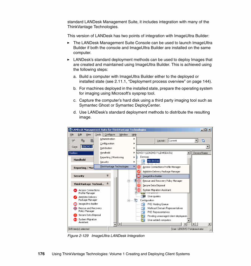
standard LANDesk Management Suite, it includes integration with many of the ThinkVantage Technologies.
This version of LANDesk has two points of integration with ImageUltra Builder:
� The LANDesk Management Suite Console can be used to launch ImageUltra Builder if both the console and ImageUltra Builder are installed on the same computer.
� LANDesk’s standard deployment methods can be used to deploy Images that are created and maintained using ImageUltra Builder. This is achieved using the following steps:
a. Build a computer with ImageUltra Builder either to the deployed or installed state (see 2.11.1, “Deployment process overview” on page 144).
b. For machines deployed in the installed state, prepare the operating system for imaging using Microsoft’s sysprep tool.
c. Capture the computer’s hard disk using a third party imaging tool such as Symantec Ghost or Symantec DeployCenter.
d. Use LANDesk’s standard deployment methods to distribute the resulting image.
Figure 2-129 ImageUltra LANDesk Integration
176 Using ThinkVantage Technologies: Volume 1 Creating and Deploying Client Systems

Figure 2-129 shows how to access ImageUltra Builder on the Tools → ThinkVantage Technologies menu or from the toolbox on the left hand side of the window.
Chapter 2. ImageUltra Builder 177

178 Using ThinkVantage Technologies: Volume 1 Creating and Deploying Client Systems
Chapter 3. System Migration Assistant
As corporations transition to new operating systems and platforms, one of the most time consuming tasks is the migration of user-specific information to a new workstation. How can an IT organization move information to a new PC without spending hours, if not days, to get a user to an operational state? Migration to Windows 2000 and Windows XP can present many challenges to an IT organization. What is the best way to get users functional in the least amount of time? Will the solution provide adequate flexibility for users to decide what information will be moved to the new PC? How can a complete solution be delivered while reducing costs?
System Migration Assistant (SMA) is a software tool that copies (or migrates) the look, feel, and personalization settings of one computer to another. The look and feel, also known as the user’s work environment, is the way the user or company has set up various computer preferences such as desktop and network connectivity settings. System Migration Assistant can also migrate files, folders, and application settings.
System Migration Assistant is a valuable tool used to upgrade from an old computer to a new system. SMA can be used with a company’s standard PC work environment for a quick and efficient migration. This standardization helps reduce the time spent deploying new computers, minimizes time spent solving problems, automates IT processes, and reduces the total cost of ownership. System Migration Assistant provides significant savings in time for system administrators. The provided functionality nearly eliminates the need to
3
© Copyright IBM Corp. 2005. All rights reserved. 179
physically configure each individual computer's desktop and working environment when deploying new machines.
System Migration Assistant excels at assisting in the migration from one PC to another or from one operating system to another, or a combination of both. System Migration Assistant has the ability to migrate user data, application settings, and operating system settings in an automated fashion.
This chapter discusses:
� 3.1, “System migration and its effects on the organization” on page 181
� 3.2, “Installation considerations” on page 182
� 3.3, “System Migration Assistant installation” on page 185
� 3.4, “Migration scenarios and types” on page 191
� 3.5, “Using System Migration Assistant” on page 193
� 3.6, “Customizing the standard migration” on page 220
� 3.7, “Creating a command file template” on page 226
� 3.8, “Customizing the command file” on page 228
� 3.9, “Performing a SMA administrative installation” on page 240
� 3.10, “Using SMA in batch mode” on page 245
� 3.11, “System Migration Assistant migration scenario” on page 248
� 3.12, “ThinkVantage integration considerations” on page 257
180 Using ThinkVantage Technologies: Volume 1 Creating and Deploying Client Systems
3.1 System migration and its effects on the organizationThe first things most people typically do when they receive a new PC are to transfer data and customize the look and feel of the PC to their preferences. A good business plan for migration needs to be created before any migration can take place. This is true regardless who does the migration. If a standardized plan is not used to execute system migrations, user productivity will drop, data loss can occur, and the total cost of ownership of the PC will increase. The organization benefits most if the system migration is done completely, quickly, and accurately. A best practice approach to system migration starts with a corporate-wide standard location for user data. This will eliminate many of the inconsistencies of user-defined data storage directories. This small step will greatly increase the success rate of any migration solution. Standardizing which files and formats are to be migrated will improve the accuracy and speed of the migration.
The length of time it takes to properly migrate an old system to a new system will be affected by two important factors.
� The first factor is the number of machines that can be migrated in any given time period. The quicker and more automated the process is, the more machines per staff hour can be migrated.
� The second point is cost. Hard costs are involved when internal IT staff or third parties are tasked to assist in the upgrade/rollout/migration. To maximize Return On Investment, a migration solution needs to minimize your migration costs. There are less tangible soft costs such as loss of productivity of users while they customize new systems and the cost of recreating data if data loss occurs during migration.
From a business standpoint, it only makes sense to have migrations completed in a standardized, comprehensive, quick, and accurate manner. This is where System Migration Assistant excels.
3.1.1 When is system migration required?In most scenarios, system migration is necessary to reduce downtime and make the user productive.
Most organizations fall into a category of networked or standalone PCs. The PCs have an operating system and local applications. The personal data is stored locally, on a network, or both. A customized SMA graphical user interface (GUI) or a batch migration can be used to do these migrations.
Chapter 3. System Migration Assistant 181
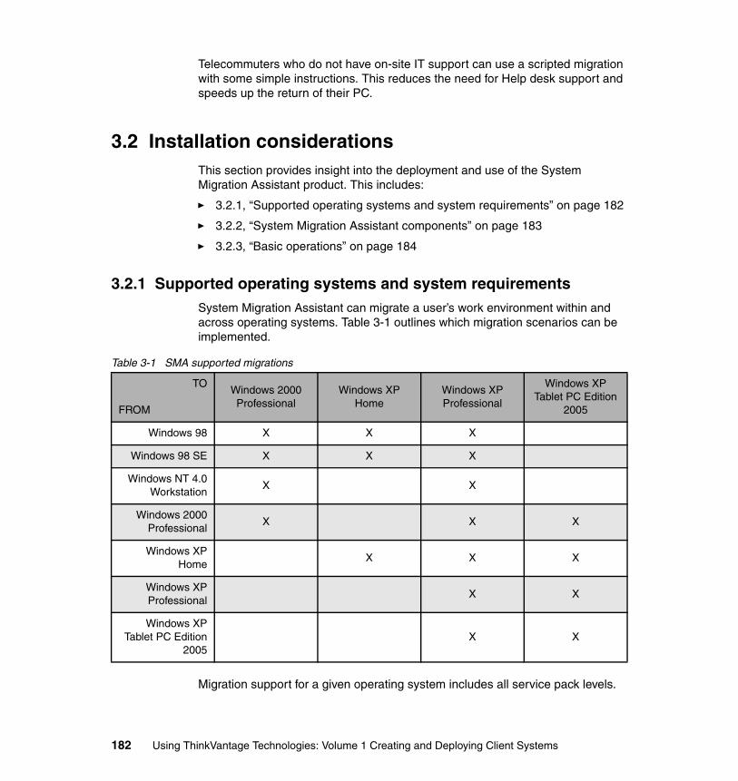
Telecommuters who do not have on-site IT support can use a scripted migration with some simple instructions. This reduces the need for Help desk support and speeds up the return of their PC.
3.2 Installation considerationsThis section provides insight into the deployment and use of the System Migration Assistant product. This includes:
� 3.2.1, “Supported operating systems and system requirements” on page 182
� 3.2.2, “System Migration Assistant components” on page 183
� 3.2.3, “Basic operations” on page 184
3.2.1 Supported operating systems and system requirementsSystem Migration Assistant can migrate a user’s work environment within and across operating systems. Table 3-1 outlines which migration scenarios can be implemented.
Table 3-1 SMA supported migrations
Migration support for a given operating system includes all service pack levels.
TO
FROM
Windows 2000 Professional
Windows XP Home
Windows XP Professional
Windows XP Tablet PC Edition
2005
Windows 98 X X X
Windows 98 SE X X X
Windows NT 4.0Workstation
X X
Windows 2000Professional
X X X
Windows XPHome
X X X
Windows XPProfessional
X X
Windows XPTablet PC Edition
2005X X
182 Using ThinkVantage Technologies: Volume 1 Creating and Deploying Client Systems
Be aware that you cannot migrate profiles between systems with different languages (for example, from an English system to a Japanese system). Also, there are a number of additional restrictions due to operating system incompatibilities. For details, see “Introducing System Migration Assistant” in the ThinkVantage System Migration Assistant 5.0 User’s Guide, or refer to:
http://www.ibm.com/pc/support/site.wss/document.do?lndocid=TVAN-SMAUG
The following requirements apply to both source and target computers unless otherwise noted. A supported Windows operating system must be installed.
� There must be about 30 MB of hard drive space to install SMA. In addition, there must be adequate drive space for temporary files.
� In general, connectivity between target and source computer is assumed for these examples. In particular, the target computer must have access to the profile file on the source computer. It is also possible to copy an SMA profile onto a removable medium, such as a USB 2.0 hard drive, and to apply the profile to a target computer that is either standalone or a client of a network that cannot be connected to the source computer.
� Certain scenarios require adequate space to store the profile and apply the profile to the target PC. The size of a profile depends on the amount of settings and data you are migrating.
3.2.2 System Migration Assistant componentsDuring a migration, System Migration Assistant takes a snapshot of the work environment. It then uses the snapshot as a blueprint to duplicate your environment on another computer. The computer on which the snapshot is taken is called the source computer. The computer to which you are migrating is called the target computer. The source and target computers can be in different physical locations. Alternatively, the source and target computer can be the same computer, with System Migration Assistant 5.0 and Rescue and Recovery 3.0 used to back up and restore settings and files.
The System Migration Assistant tool contains the following files:
� SMA.EXE An executable that captures a variety of settings and files on a source computer, and copies these to a migration file. The same executable is also used to apply the migration file to a target computer.
� CONFIG.INI A configuration file used to customize the SMA.EXE executable, in particular its graphical user interface.
� SMABAT.EXE A command line interface executable for use in batch mode that is functionally equivalent to SMA.EXE.
� COMMANDS.XML A command file used to drive the capture and migrate process in a batch.
Chapter 3. System Migration Assistant 183
� <APPLICATION NAME>.XML An application file used to define how to capture and apply application settings by system migration assistant.
3.2.3 Basic operationsThis section describes the basic procedures you are likely to run with System Migration Assistant after you have installed the software. Later sections describe this functionality in detail.
SMA migrates the work environment of one computer to another in two steps:
1. Customize System Migration Assistant to capture the desired settings and data. Then SMA copies these settings and files to a migration file also known as a profile. This is called the capture phase.
2. System Migration Assistant uses the profile to copy the settings and files to the target computer. This is called the apply phase.
During the capture phase, you need to tell System Migration Assistant what to migrate from the source computer. This is the first step during any standard migration, including when it is run in batch mode. You can capture the following settings:
� Desktop settings: Examples are the active desktop, colors, desktop icons, display, icon font, pattern, screen saver, and wallpaper.
� Printer settings: This includes local and network printer settings.
� Network settings: Examples are the computer description, computer name, TCP/IP configuration, mapped drives, dial-up networking settings, and shared folders and drives.
� Application settings: Customization and configuration settings of various supported applications.
� Files: There is no limit to the number of files that you can capture as long as there is sufficient disk space to store the captured data. You can copy these files to the same location on the target computer or relocate them to a different directory.
� User profiles: Both local and domain user profiles.
During the apply phase, SMA copies the profile to the target computer. Apply the entire profile or just selected components of the profile before copying it. This is the second step during any standard migration, including when it is run in batch mode.
Restriction: The data format of a SMA V5.0 migration file is not compatible with SMA V4.x and earlier.
184 Using ThinkVantage Technologies: Volume 1 Creating and Deploying Client Systems
3.3 System Migration Assistant installation You can install System Migration Assistant (SMA) V5.0 over previous versions of System Migration Assistant 4.1 and 4.2 without the need to remove the older version.
There are two types of SMA installation:
� Standard installation: To perform a standard installation of SMA, you must first log on locally to the computer, using an operating system account with administrative privileges and running the installation from that computer.
� Silent installation: To install SMA without any interaction with a user, you log on to the networked environment and remotely install SMA on one or more computers. Silent installations are usually done remotely. We discuss administrative installation with a customized config.ini and commands.xml later.
Note: If the information you migrate is data, you may not need the application. However, if you migrate the configuration files of an application, then you should install the application for the settings to be useful on the new machine.
Chapter 3. System Migration Assistant 185
Figure 3-1 System Migration Assistant 5.0
3.3.1 Extracting the System Migration Assistant executable1. Log on to the computer, using an operating system account with
administrative privileges.
2. Download the current version of the SMA compressed file from:
http://www.ibm.com/pc/support/site.wss/document.do?lndocid=MIGR-50889&sitestyle=lenovo
3. Run the sa5048.EXE that you downloaded from the internet.
4. Click Next on InstallShield Wizard window.
5. To accept the SMA License Agreement, select I accept the terms in the license agreement. Click Next to continue.
6. Choose where you want the program to be extracted. Click Next to accept the default or Browse to select a different location. See Figure 3-2.
186 Using ThinkVantage Technologies: Volume 1 Creating and Deploying Client Systems
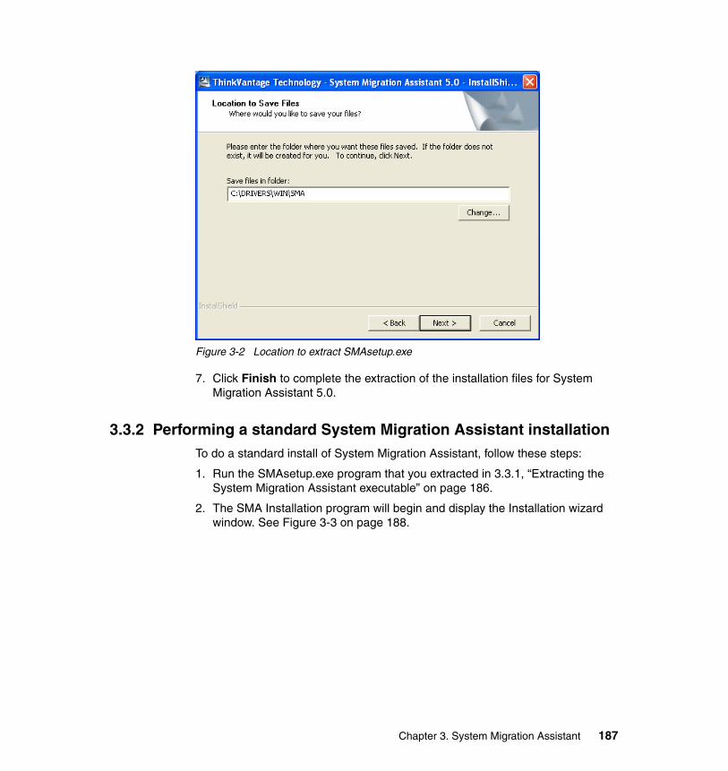
Figure 3-2 Location to extract SMAsetup.exe
7. Click Finish to complete the extraction of the installation files for System Migration Assistant 5.0.
3.3.2 Performing a standard System Migration Assistant installationTo do a standard install of System Migration Assistant, follow these steps:
1. Run the SMAsetup.exe program that you extracted in 3.3.1, “Extracting the System Migration Assistant executable” on page 186.
2. The SMA Installation program will begin and display the Installation wizard window. See Figure 3-3 on page 188.
Chapter 3. System Migration Assistant 187
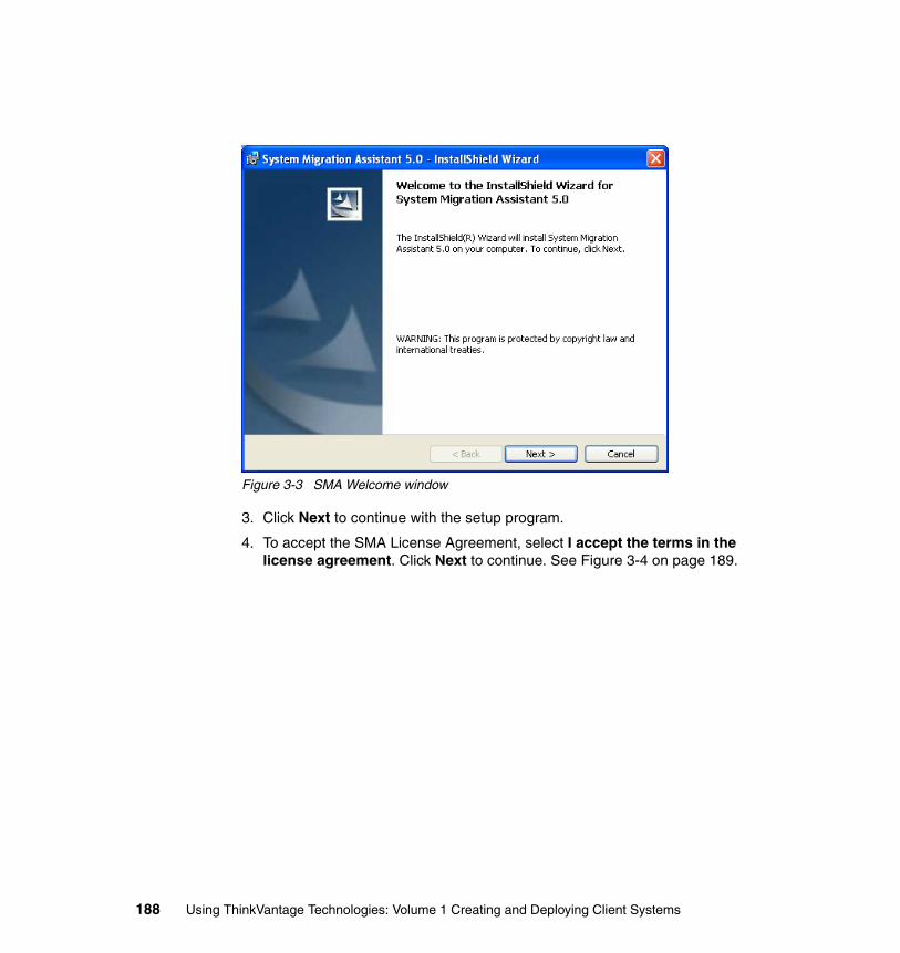
Figure 3-3 SMA Welcome window
3. Click Next to continue with the setup program.
4. To accept the SMA License Agreement, select I accept the terms in the license agreement. Click Next to continue. See Figure 3-4 on page 189.
188 Using ThinkVantage Technologies: Volume 1 Creating and Deploying Client Systems
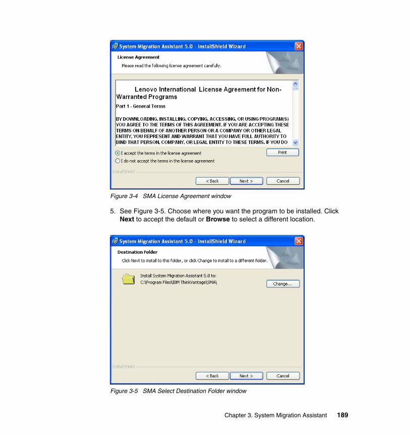
Figure 3-4 SMA License Agreement window
5. See Figure 3-5. Choose where you want the program to be installed. Click Next to accept the default or Browse to select a different location.
Figure 3-5 SMA Select Destination Folder window
Chapter 3. System Migration Assistant 189
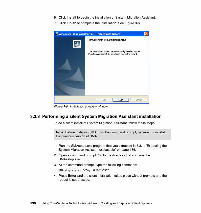
6. Click Install to begin the installation of System Migration Assistant.
7. Click Finish to complete the installation. See Figure 3-6.
Figure 3-6 Installation complete window
3.3.3 Performing a silent System Migration Assistant installationTo do a silent install of System Migration Assistant, follow these steps:
1. Run the SMAsetup.exe program that you extracted in 3.3.1, “Extracting the System Migration Assistant executable” on page 186.
2. Open a command prompt. Go to the directory that contains the SMAsetup.exe.
3. At the command prompt, type the following command:
SMAsetup.exe /s /v”/qn REBOOT=”R””
4. Press Enter and the silent installation takes place without prompts and the reboot is suppressed.
Note: Before installing SMA from the command prompt, be sure to uninstall the previous version of SMA.
190 Using ThinkVantage Technologies: Volume 1 Creating and Deploying Client Systems
3.3.4 Uninstalling System Migration Assistant The following procedure permanently removes the SMA program files:
1. Select Control Panel.
2. Select Add/Remove Programs.
3. Select System Migration Assistant 5.0.
4. Click Remove.
5. Click Yes to confirm removal of SMA. The uninstall process will now start.
6. During the uninstall, it may prompt to remove unused shared files. Click either button depending on whether you want to preserve files or not.
Uninstalling System Migration Assistant does not delete all files. You need to manually remove these files if desired.
� SMA log files generated whenever SMA is run. These files are located at the root of the C: drive unless the default copy location was changed.
� Temporary files specific to SMA. By default, these files are in the d:\Install location\etc\data, where d is the drive letter of the hard disk drive.
� SMA migration files (for example, files with an .sma extension).
3.4 Migration scenarios and typesSystem Migration Assistant V5.0 supports two basic migration scenarios:
1. Target initiated migration
If you have SMA installed on the target computer, you can start migration without installing SMA on the source computer. On the target computer, SMA will copy the SMA installation package to a removable media or memory, install SMA on the source computer, and then start the migration.
2. Standard migration
You need to install SMA on both computers separately, and then you can start the migration process on the source computer.
For each of the migration scenarios, two types of migration are supported:
1. Typical migration
Note: Type SMAsetup.exe /? in the command prompt to view the command line parameters for the SMA installation executable.
Chapter 3. System Migration Assistant 191
You have to select the files you are going to migrate; then all of your application data, settings, and your selected files will be migrated. This is a simple and quick way to migrate.
You can run the typical migration from the GUI and we recommend this type of migration for all users.
2. Custom migration
You have to select all of your data, settings, and files for migration. Several windows display during the selection process allowing you to make specific selections of settings to migrate.
Run the custom migration either from the GUI or from a command-line prompt. It requires advanced knowledge of SMA, and we recommend this custom migration for users such as IT administrators.
System Migration Assistant migrates the custom working environment of one computer to another in two or three phases:
1. Capture phase (see 3.2.3, “Basic operations” on page 184) for all users
2. Apply phase (see 3.2.3, “Basic operations” on page 184) for the user logged on to the computer as a local administrator
3. Delayed apply phase for users without administrator privileges
Typical migrationCapture phaseIn the capture phase of the typical migration for a single user logged on as an administrator, the following items, which are preselected and cannot be deselected, can be copied from the source computer:
� Desktop settings� Printer settings� Network settings� Application settings
You can then select files and folders to migrate. These settings and files are stored in an SMA migration file.
Apply phaseDuring the apply phase, SMA applies the migration file to the administrator user of the target computer. A typical migration applies the entire migration file. A custom migration allows you to specify the components of the migration file that you want to apply.
192 Using ThinkVantage Technologies: Volume 1 Creating and Deploying Client Systems
Custom migrationCapture phaseIn the capture phase of a custom migration for a user logged on as an administrator and other background users not logged at the time of migration, the following items can be selected and copied from the source computer:
� Desktop settings� Printer settings� Network settings� Application settings� Files and folders� User profiles for background users
The files and settings are stored in the SMA migration file.
Apply phaseDuring the apply phase, SMA performs two tasks:
� SMA applies the migration file to the administrator user of the target computer. You can apply the entire migration file, or you can specify the components of the migration file that you want to apply.
� SMA prepares the delayed apply tasks for other users.
A custom migration allows you to specify the components of the migration file that you want to apply.
When users without the administrative privilege log on to the computer for the first time, the settings for their profiles are applied automatically.
3.5 Using System Migration AssistantThe following example migration is a standard migration (SMA installed on both computers, migration initiated on the source computer) using a migration file (no physical connection between the source and target computer is required). A custom migration is selected, allowing specific selection of settings to be migrated.
3.5.1 Capturing settings and filesThe profile or migration file is the basis of a migration and is the main output of the capture phase. The profile contains all the settings and files to be applied to one or more target computers. During the capture phase, you specify which settings and files to migrate. Before selecting the settings on the source computer, make sure that all the settings you want to capture are correct. Before
Chapter 3. System Migration Assistant 193
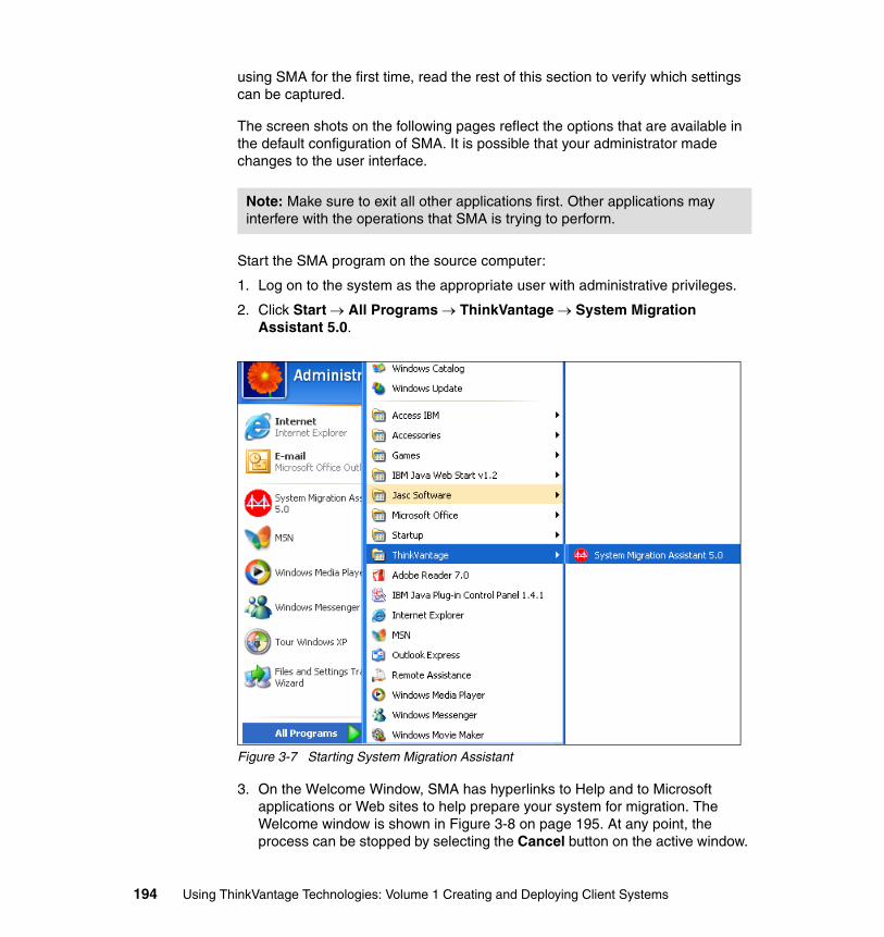
using SMA for the first time, read the rest of this section to verify which settings can be captured.
The screen shots on the following pages reflect the options that are available in the default configuration of SMA. It is possible that your administrator made changes to the user interface.
Start the SMA program on the source computer:
1. Log on to the system as the appropriate user with administrative privileges.
2. Click Start → All Programs → ThinkVantage → System Migration Assistant 5.0.
Figure 3-7 Starting System Migration Assistant
3. On the Welcome Window, SMA has hyperlinks to Help and to Microsoft applications or Web sites to help prepare your system for migration. The Welcome window is shown in Figure 3-8 on page 195. At any point, the process can be stopped by selecting the Cancel button on the active window.
Note: Make sure to exit all other applications first. Other applications may interfere with the operations that SMA is trying to perform.
194 Using ThinkVantage Technologies: Volume 1 Creating and Deploying Client Systems
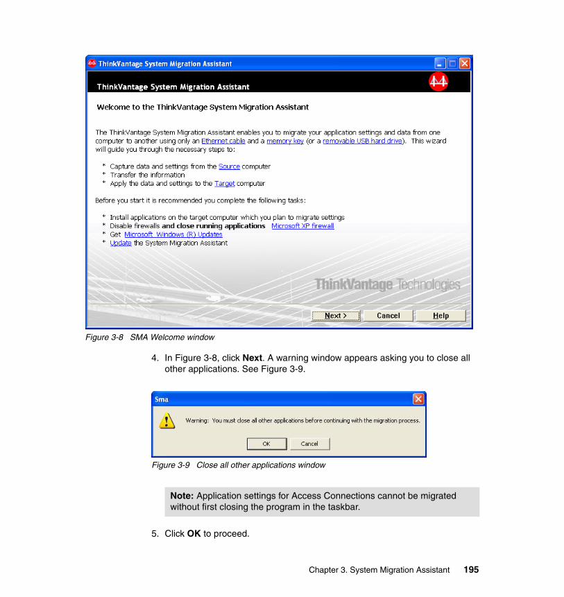
Figure 3-8 SMA Welcome window
4. In Figure 3-8, click Next. A warning window appears asking you to close all other applications. See Figure 3-9.
Figure 3-9 Close all other applications window
5. Click OK to proceed.
Note: Application settings for Access Connections cannot be migrated without first closing the program in the taskbar.
Chapter 3. System Migration Assistant 195
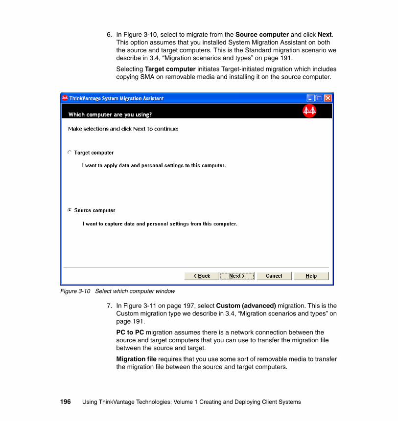
6. In Figure 3-10, select to migrate from the Source computer and click Next. This option assumes that you installed System Migration Assistant on both the source and target computers. This is the Standard migration scenario we describe in 3.4, “Migration scenarios and types” on page 191.
Selecting Target computer initiates Target-initiated migration which includes copying SMA on removable media and installing it on the source computer.
Figure 3-10 Select which computer window
7. In Figure 3-11 on page 197, select Custom (advanced) migration. This is the Custom migration type we describe in 3.4, “Migration scenarios and types” on page 191.
PC to PC migration assumes there is a network connection between the source and target computers that you can use to transfer the migration file between the source and target.
Migration file requires that you use some sort of removable media to transfer the migration file between the source and target computers.
196 Using ThinkVantage Technologies: Volume 1 Creating and Deploying Client Systems
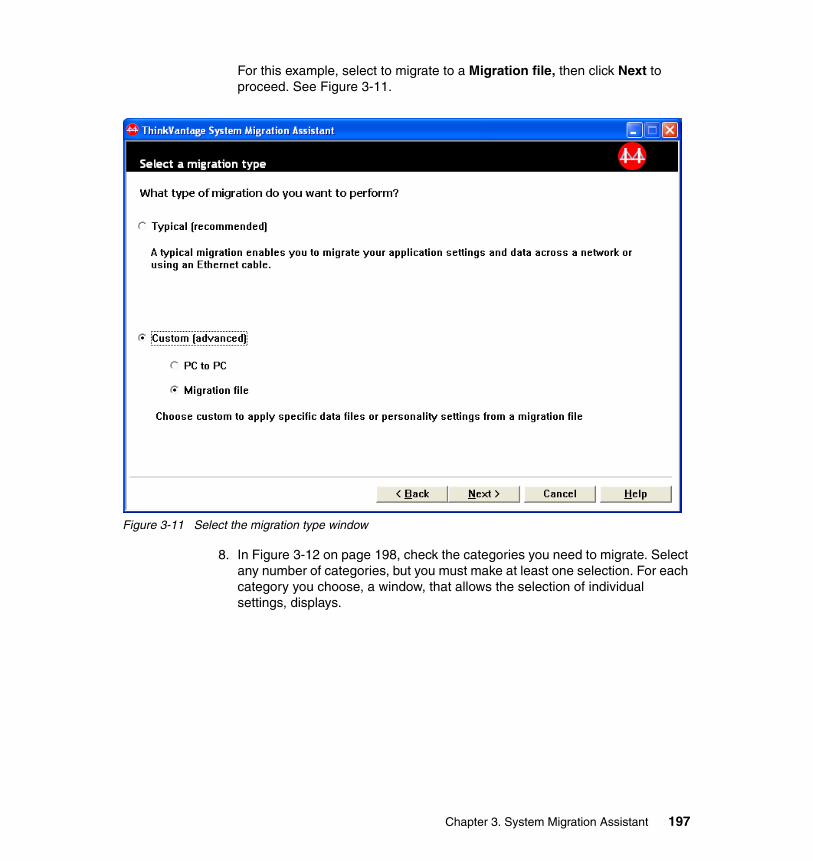
For this example, select to migrate to a Migration file, then click Next to proceed. See Figure 3-11.
Figure 3-11 Select the migration type window
8. In Figure 3-12 on page 198, check the categories you need to migrate. Select any number of categories, but you must make at least one selection. For each category you choose, a window, that allows the selection of individual settings, displays.
Chapter 3. System Migration Assistant 197
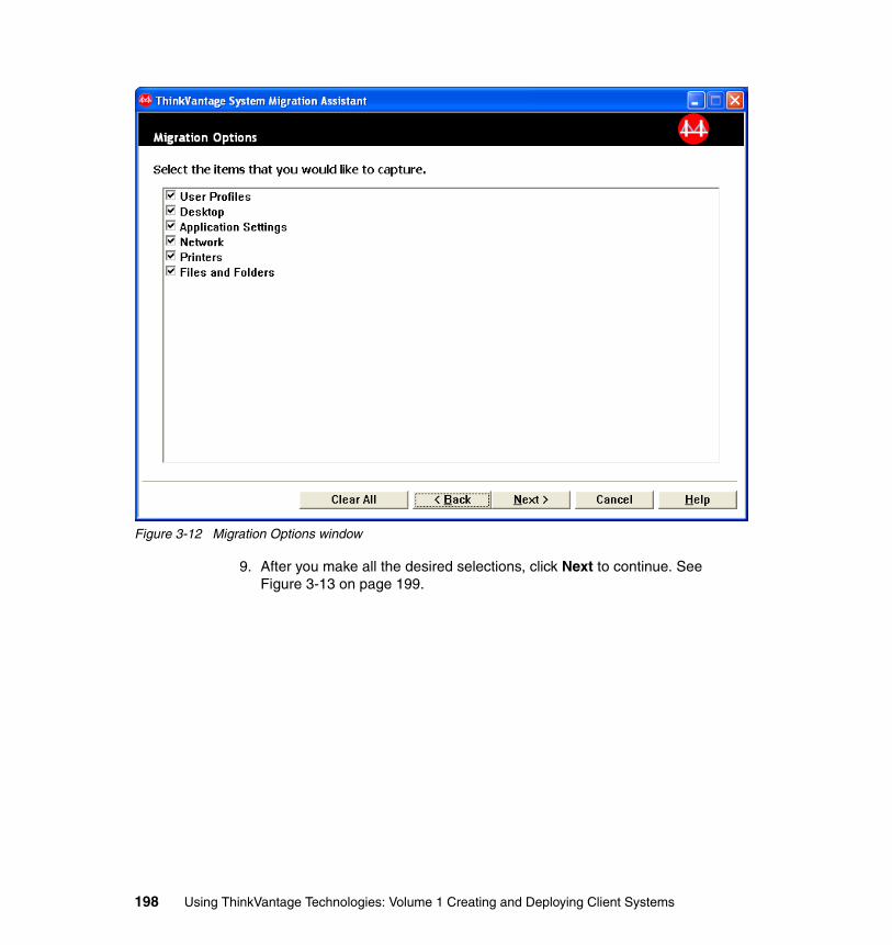
Figure 3-12 Migration Options window
9. After you make all the desired selections, click Next to continue. See Figure 3-13 on page 199.
198 Using ThinkVantage Technologies: Volume 1 Creating and Deploying Client Systems
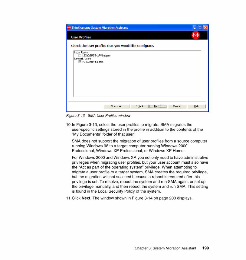
Figure 3-13 SMA User Profiles window
10.In Figure 3-13, select the user profiles to migrate. SMA migrates the user-specific settings stored in the profile in addition to the contents of the “My Documents” folder of that user.
SMA does not support the migration of user profiles from a source computer running Windows 98 to a target computer running Windows 2000 Professional, Windows XP Professional, or Windows XP Home.
For Windows 2000 and Windows XP, you not only need to have administrative privileges when migrating user profiles, but your user account must also have the “Act as part of the operating system” privilege. When attempting to migrate a user profile to a target system, SMA creates the required privilege, but the migration will not succeed because a reboot is required after this privilege is set. To resolve, reboot the system and run SMA again, or set up the privilege manually, and then reboot the system and run SMA. This setting is found in the Local Security Policy of the system.
11.Click Next. The window shown in Figure 3-14 on page 200 displays.
Chapter 3. System Migration Assistant 199
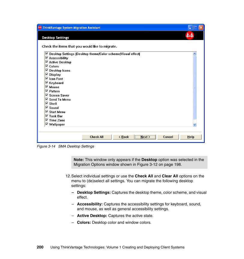
Figure 3-14 SMA Desktop Settings
12.Select individual settings or use the Check All and Clear All options on the menu to (de)select all settings. You can migrate the following desktop settings:
– Desktop Settings: Captures the desktop theme, color scheme, and visual effect.
– Accessibility: Captures the accessibility settings for keyboard, sound, and mouse, as well as general accessibility settings.
– Active Desktop: Captures the active state.
– Colors: Desktop color and window colors.
Note: This window only appears if the Desktop option was selected in the Migration Options window shown in Figure 3-12 on page 198.
200 Using ThinkVantage Technologies: Volume 1 Creating and Deploying Client Systems
– Desktop Icons: All desktop contents, including folders and file shortcuts, icons, and icon positions.
– Display: Desktop width, height, and color depth.
– Icon Font: Captures the icon font.
– Keyboard: Keyboard repeat rate, cursor blink rate, and delay.
– Mouse: Left- or right-handed mouse settings, speed, and double-click time.
– Pattern: Desktop pattern.
– Screen Saver: Current screen saver settings.
– Send To Menu: Send To menu settings.
– Shell: View sort order, view type (larger icon, small icon), show/hide status bar/toolbar.
– Sound: Sound settings.
– Start Menu: Start menu commands.
– Task Bar: Docking edge, size, always-on-top, auto hide, show clock, and show small icons in Start menu.
– Time Zone: Clock time zone.
– Wallpaper: Desktop wallpaper.
– Window Metrics: Spacing and arrangement order of minimized windows, message dialog font, menu size, and scroll bar sizes.
The following migration restrictions apply to the desktop settings:
– Accessibility: If migrating from Windows 98 to Windows 2000 Professional/Server, the ShowSounds, SoundSentry, and Stickykeys settings cannot be migrated.
– Active Desktop: To migrate the Active Desktop, including the wallpaper, the wallpaper setting must be selected. Active Desktop is not supported for Windows XP Professional.
– Pattern: Pattern settings cannot be migrated from any operating system to a computer running Windows XP Professional.
– Screen Saver: Cannot migrate the screen saver if migrating from Windows 95/98 to Windows 2000 Professional.
Note: Desktop icons that do not link to an application or file will not be migrated.
Chapter 3. System Migration Assistant 201

– Shell: In order for the Windows Explorer shell settings to migrate properly, both shell desktop settings and the Microsoft Internet Explorer application settings must be migrated to migrate the shell settings. If Windows XP is the target system, the folder view settings (Large Icons, Tiles, Details, and so on) fail to migrate.
– Sound: To migrate sounds, at least one sound must be selected in the Sounds and Multimedia window located in the Control Panel. If no sounds were used, for instance, by selecting the No Sounds scheme in this window, these settings will not migrate successfully. In addition, sound files (for example: .WAV files) are not migrated when the sound option is selected. In most cases, this will not cause an issue since the operating systems use many of the same sound schemes. If custom-created sounds were created, or you are using a sound scheme not known on the other operating system, then these sound files need to be migrated as well.
– Taskbar: The taskbar settings are not migrated for background users. Only the foreground user’s taskbar is captured.
– Wallpaper: To migrate the wallpaper file that is .jpg type, the Active Desktop setting must be captured in source in order to activate it on the desktop. Note that it is not necessary to capture the Active desktop® setting when migrating wallpaper that is .bmp file type.
13.Click Next. The window shown in Figure 3-15 on page 203 displays.
202 Using ThinkVantage Technologies: Volume 1 Creating and Deploying Client Systems
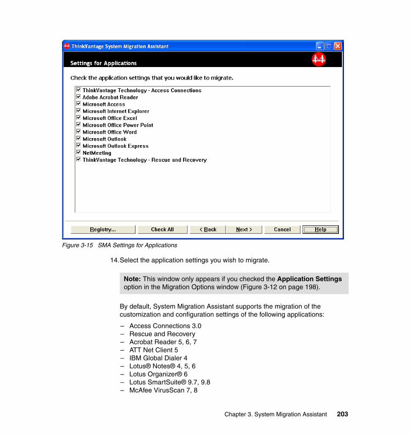
Figure 3-15 SMA Settings for Applications
14.Select the application settings you wish to migrate.
By default, System Migration Assistant supports the migration of the customization and configuration settings of the following applications:
– Access Connections 3.0– Rescue and Recovery– Acrobat Reader 5, 6, 7– ATT Net Client 5– IBM Global Dialer 4– Lotus® Notes® 4, 5, 6– Lotus Organizer® 6– Lotus SmartSuite® 9.7, 9.8– McAfee VirusScan 7, 8
Note: This window only appears if you checked the Application Settings option in the Migration Options window (Figure 3-12 on page 198).
Chapter 3. System Migration Assistant 203
– Microsoft Access 2000, XP, 2003– Microsoft Internet Explorer 5.0, 5.5, 6.0– Microsoft Office 97, 2000, XP, 2003– Microsoft Outlook® 98, 2000, XP, 2003– Microsoft Outlook Express 4.x, 5.x, 6.x– Microsoft Project 98, 2000, 2002– Microsoft Visio® 2000, 2002– MSN® Messenger 5.x, 6.x– NetMeeting® 2.x, 3.x– Netscape 6.x, 7.x– NortonAntiVirus 7.x– Symantec Antivirus 9.x– WinZip 8.x
For Internet Explorer and Netscape Navigator, SMA migrates the customizations that the user has made to the browser. These include Bookmarks, Cookies, Favorites, History Folder, and AutoComplete. Similarly for the other applications, SMA captures all customizations that will enable the same look and feel on the target computer. This includes the address book and locally stored e-mail for Lotus Notes and Microsoft Outlook, but does not include separate data files such as spreadsheets and word documents in Microsoft Office 2000. Also, note that the application itself is not migrated.
The following migration restrictions apply to the application settings:
– One of the application settings that can be migrated is the most recently used files (or history of files). In order for this setting to work, the corresponding files must be migrated and placed in the same directory path on the target computer as the directory path on the source computer used in 3.5.1, “Capturing settings and files” on page 193.
– Some applications do not support cross-version migration. Most settings will not transfer in the following scenarios:
• Office 97 to Office 2000/XP (no settings migrate) • Office 2000 to Office XP (partial settings migrate) • Visio 2000 to Visio 2002 (partial settings migrate) • AT&T Net Client 4 to AT&T Net Client 5 (no settings migrate) • Lotus Notes 4 to Lotus Notes 5 (partial settings migrate) • Outlook 98 to Outlook 2000/XP (partial settings migrate) • Outlook 2000 to Outlook XP (partial settings migrate); for Outlook,
most key settings (mail file, address book, and so on) do migrate successfully.
Note: For more information about migrating application settings, refer to the ThinkVantage System Migration Assistant 5.0 User’s Guide at:
http://www.ibm.com/pc/support/site.wss/document.do?lndocid=TVAN-SMAUG
204 Using ThinkVantage Technologies: Volume 1 Creating and Deploying Client Systems
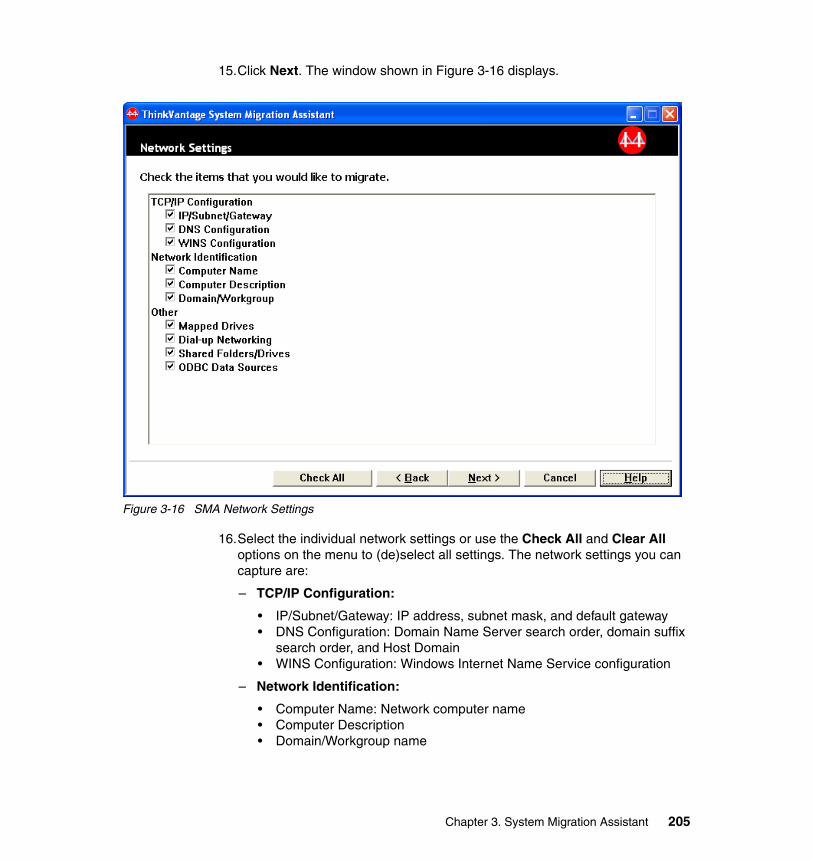
15.Click Next. The window shown in Figure 3-16 displays.
Figure 3-16 SMA Network Settings
16.Select the individual network settings or use the Check All and Clear All options on the menu to (de)select all settings. The network settings you can capture are:
– TCP/IP Configuration:
• IP/Subnet/Gateway: IP address, subnet mask, and default gateway • DNS Configuration: Domain Name Server search order, domain suffix
search order, and Host Domain • WINS Configuration: Windows Internet Name Service configuration
– Network Identification:
• Computer Name: Network computer name • Computer Description • Domain/Workgroup name
Chapter 3. System Migration Assistant 205
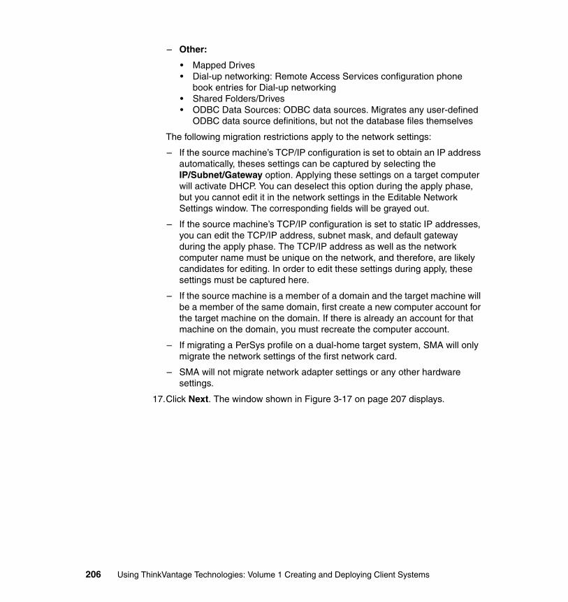
– Other:
• Mapped Drives • Dial-up networking: Remote Access Services configuration phone
book entries for Dial-up networking • Shared Folders/Drives • ODBC Data Sources: ODBC data sources. Migrates any user-defined
ODBC data source definitions, but not the database files themselves
The following migration restrictions apply to the network settings:
– If the source machine’s TCP/IP configuration is set to obtain an IP address automatically, theses settings can be captured by selecting the IP/Subnet/Gateway option. Applying these settings on a target computer will activate DHCP. You can deselect this option during the apply phase, but you cannot edit it in the network settings in the Editable Network Settings window. The corresponding fields will be grayed out.
– If the source machine’s TCP/IP configuration is set to static IP addresses, you can edit the TCP/IP address, subnet mask, and default gateway during the apply phase. The TCP/IP address as well as the network computer name must be unique on the network, and therefore, are likely candidates for editing. In order to edit these settings during apply, these settings must be captured here.
– If the source machine is a member of a domain and the target machine will be a member of the same domain, first create a new computer account for the target machine on the domain. If there is already an account for that machine on the domain, you must recreate the computer account.
– If migrating a PerSys profile on a dual-home target system, SMA will only migrate the network settings of the first network card.
– SMA will not migrate network adapter settings or any other hardware settings.
17.Click Next. The window shown in Figure 3-17 on page 207 displays.
206 Using ThinkVantage Technologies: Volume 1 Creating and Deploying Client Systems
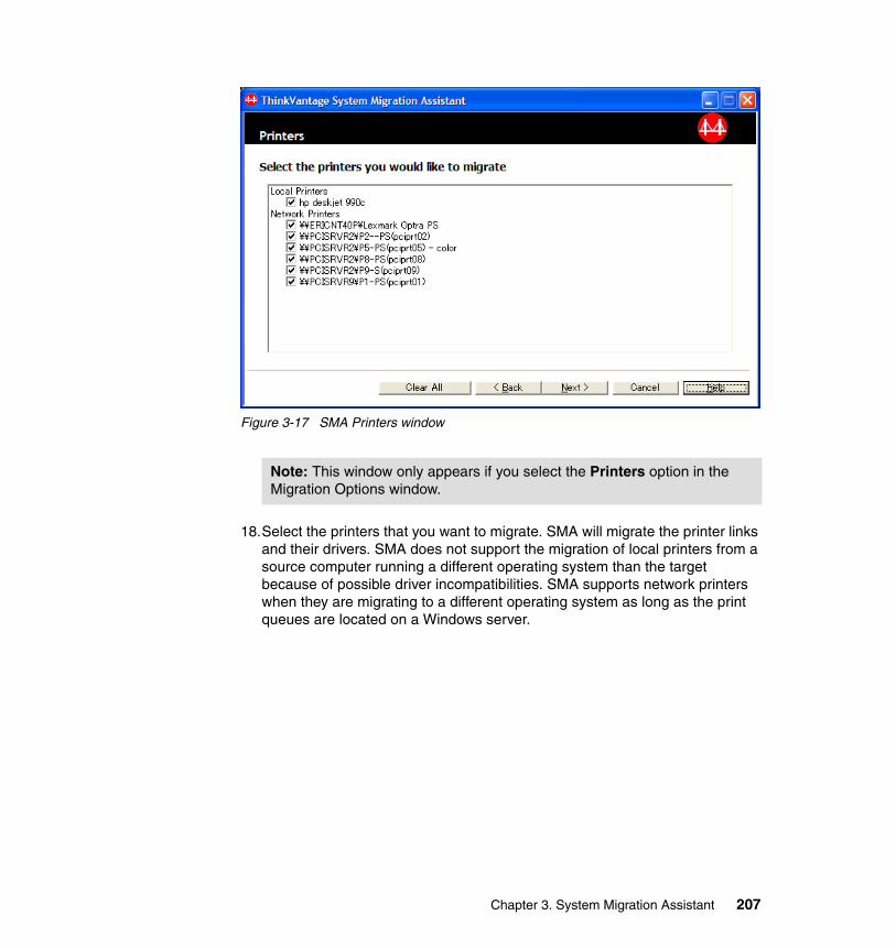
Figure 3-17 SMA Printers window
18.Select the printers that you want to migrate. SMA will migrate the printer links and their drivers. SMA does not support the migration of local printers from a source computer running a different operating system than the target because of possible driver incompatibilities. SMA supports network printers when they are migrating to a different operating system as long as the print queues are located on a Windows server.
Note: This window only appears if you select the Printers option in the Migration Options window.
Chapter 3. System Migration Assistant 207
19.Click Next. The window shown in Figure 3-18 displays.
Figure 3-18 SMA File Selection window
SMA needs to scan the hard drives on the source machine before this window can become fully available. While SMA is scanning, the window indicates the scanning status. Wait until this process has finished.
In the File Selection window, SMA can transfer any selection of files and folders. If you check a folder for migration, its entire contents are selected, including files and the content of subfolders.
As you select files or folders, a message similar to the one shown in Figure 3-19 on page 209 may display.
Note: This window only appears if you selected the Files and Folders option in the Migration Options window.
208 Using ThinkVantage Technologies: Volume 1 Creating and Deploying Client Systems
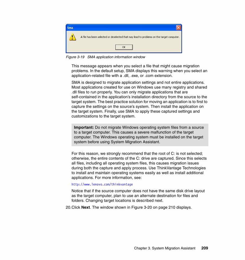
Figure 3-19 SMA application information window
This message appears when you select a file that might cause migration problems. In the default setup, SMA displays this warning when you select an application-related file with a .dll, .exe, or .com extension.
SMA is designed to migrate application settings and not entire applications. Most applications created for use on Windows use many registry and shared .dll files to run properly. You can only migrate applications that are self-contained in the application’s installation directory from the source to the target system. The best practice solution for moving an application is to first to capture the settings on the source’s system. Then install the application on the target system. Finally, use SMA to apply these captured settings and customizations to the target system.
For this reason, we strongly recommend that the root of C: is not selected; otherwise, the entire contents of the C: drive are captured. Since this selects all files, including all operating system files, this causes migration issues during both the capture and apply process. Use ThinkVantage Technologies to install and maintain operating systems easily as well as install additional applications. For more information, see:
http://www.lenovo.com/thinkvantage
Notice that if the source computer does not have the same disk drive layout as the target computer, plan to use an alternate destination for files and folders. Changing target locations is described next.
20.Click Next. The window shown in Figure 3-20 on page 210 displays.
Important: Do not migrate Windows operating system files from a source to a target computer. This causes a severe malfunction of the target computer. The Windows operating system must be installed on the target system before using System Migration Assistant.
Chapter 3. System Migration Assistant 209
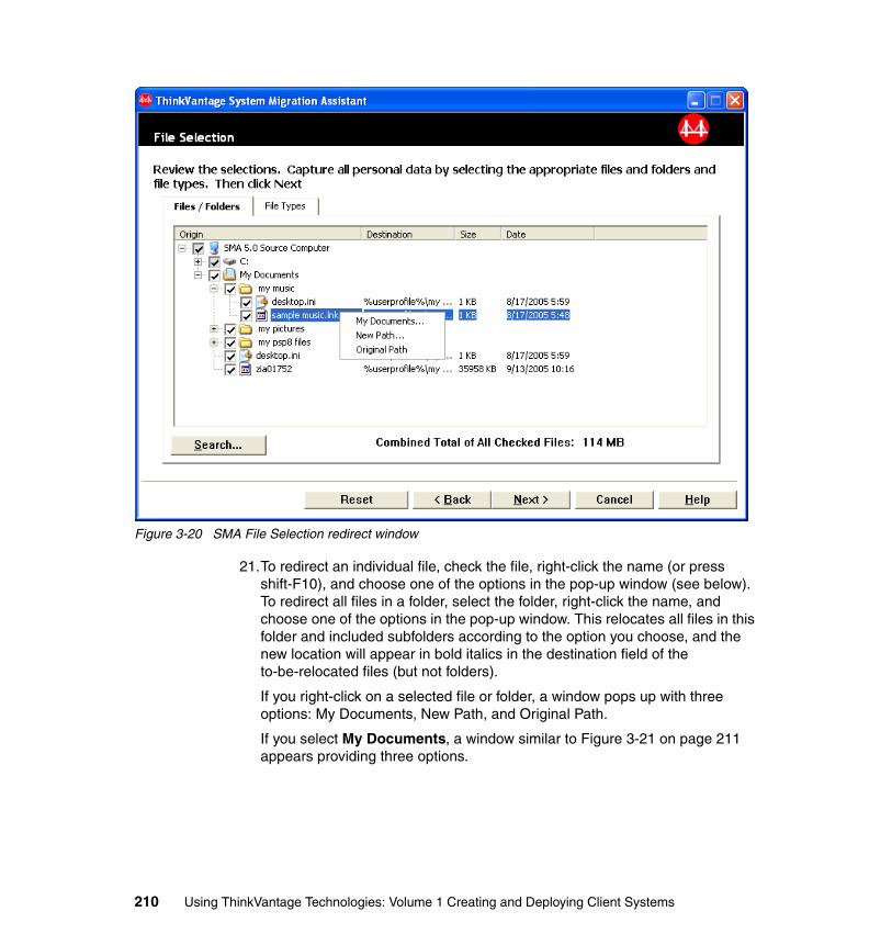
Figure 3-20 SMA File Selection redirect window
21.To redirect an individual file, check the file, right-click the name (or press shift-F10), and choose one of the options in the pop-up window (see below). To redirect all files in a folder, select the folder, right-click the name, and choose one of the options in the pop-up window. This relocates all files in this folder and included subfolders according to the option you choose, and the new location will appear in bold italics in the destination field of the to-be-relocated files (but not folders).
If you right-click on a selected file or folder, a window pops up with three options: My Documents, New Path, and Original Path.
If you select My Documents, a window similar to Figure 3-21 on page 211 appears providing three options.
210 Using ThinkVantage Technologies: Volume 1 Creating and Deploying Client Systems
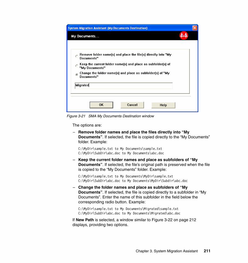
Figure 3-21 SMA My Documents Destination window
The options are:
– Remove folder names and place the files directly into “My Documents”. If selected, the file is copied directly to the “My Documents” folder. Example:
C:\MyDir\sample.txt to My Documents\sample.txt C:\MyDir\SubDir\abc.doc to My Documents\abc.doc
– Keep the current folder names and place as subfolders of “My Documents”. If selected, the file’s original path is preserved when the file is copied to the “My Documents” folder. Example:
C:\MyDir\sample.txt to My Documents\MyDir\sample.txt C:\MyDir\SubDir\abc.doc to My Documents\MyDir\Subdir\abc.doc
– Change the folder names and place as subfolders of “My Documents”. If selected, the file is copied directly to a subfolder in “My Documents”. Enter the name of this subfolder in the field below the corresponding radio button. Example:
C:\MyDir\sample.txt to My Documents\Migrated\sample.txt C:\MyDir\SubDir\abc.doc to My Documents\Migrated\abc.doc
If New Path is selected, a window similar to Figure 3-22 on page 212 displays, providing two options.
Chapter 3. System Migration Assistant 211
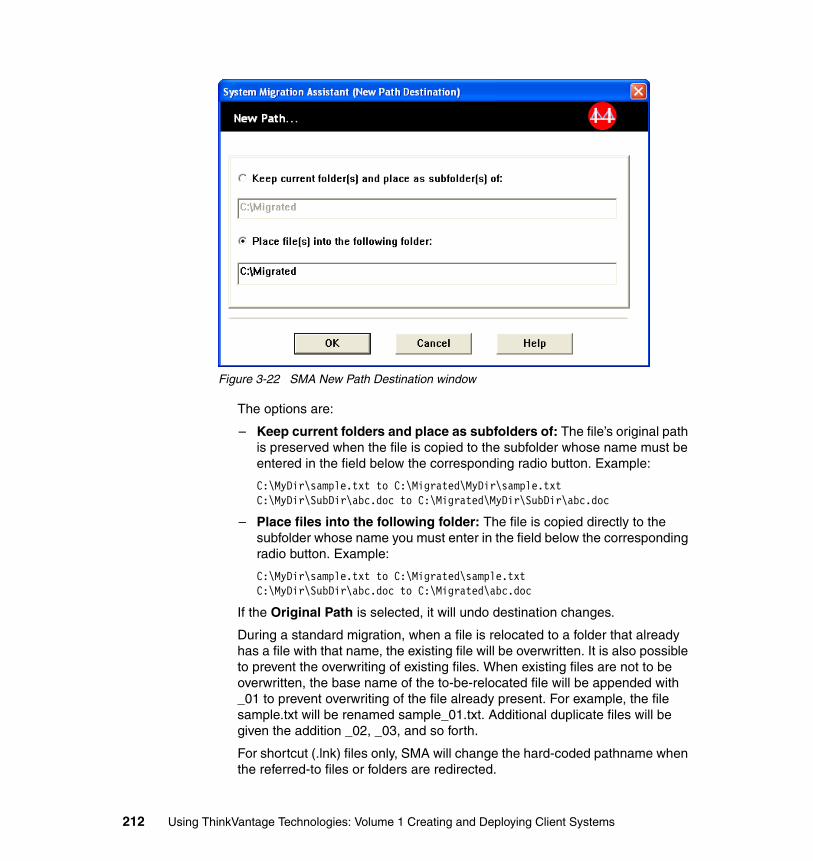
Figure 3-22 SMA New Path Destination window
The options are:
– Keep current folders and place as subfolders of: The file’s original path is preserved when the file is copied to the subfolder whose name must be entered in the field below the corresponding radio button. Example:
C:\MyDir\sample.txt to C:\Migrated\MyDir\sample.txt C:\MyDir\SubDir\abc.doc to C:\Migrated\MyDir\SubDir\abc.doc
– Place files into the following folder: The file is copied directly to the subfolder whose name you must enter in the field below the corresponding radio button. Example:
C:\MyDir\sample.txt to C:\Migrated\sample.txt C:\MyDir\SubDir\abc.doc to C:\Migrated\abc.doc
If the Original Path is selected, it will undo destination changes.
During a standard migration, when a file is relocated to a folder that already has a file with that name, the existing file will be overwritten. It is also possible to prevent the overwriting of existing files. When existing files are not to be overwritten, the base name of the to-be-relocated file will be appended with _01 to prevent overwriting of the file already present. For example, the file sample.txt will be renamed sample_01.txt. Additional duplicate files will be given the addition _02, _03, and so forth.
For shortcut (.lnk) files only, SMA will change the hard-coded pathname when the referred-to files or folders are redirected.
212 Using ThinkVantage Technologies: Volume 1 Creating and Deploying Client Systems
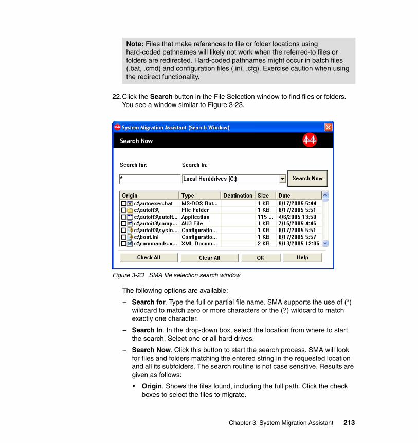
22.Click the Search button in the File Selection window to find files or folders. You see a window similar to Figure 3-23.
Figure 3-23 SMA file selection search window
The following options are available:
– Search for. Type the full or partial file name. SMA supports the use of (*) wildcard to match zero or more characters or the (?) wildcard to match exactly one character.
– Search In. In the drop-down box, select the location from where to start the search. Select one or all hard drives.
– Search Now. Click this button to start the search process. SMA will look for files and folders matching the entered string in the requested location and all its subfolders. The search routine is not case sensitive. Results are given as follows:
• Origin. Shows the files found, including the full path. Click the check boxes to select the files to migrate.
Note: Files that make references to file or folder locations using hard-coded pathnames will likely not work when the referred-to files or folders are redirected. Hard-coded pathnames might occur in batch files (.bat, .cmd) and configuration files (.ini, .cfg). Exercise caution when using the redirect functionality.
Chapter 3. System Migration Assistant 213
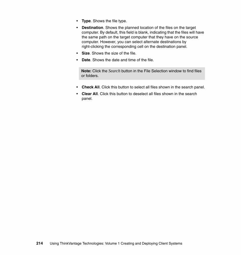
• Type. Shows the file type.
• Destination. Shows the planned location of the files on the target computer. By default, this field is blank, indicating that the files will have the same path on the target computer that they have on the source computer. However, you can select alternate destinations by right-clicking the corresponding cell on the destination panel.
• Size. Shows the size of the file.
• Date. Shows the date and time of the file.
• Check All. Click this button to select all files shown in the search panel.
• Clear All. Click this button to deselect all files shown in the search panel.
Note: Click the Search button in the File Selection window to find files or folders.
214 Using ThinkVantage Technologies: Volume 1 Creating and Deploying Client Systems
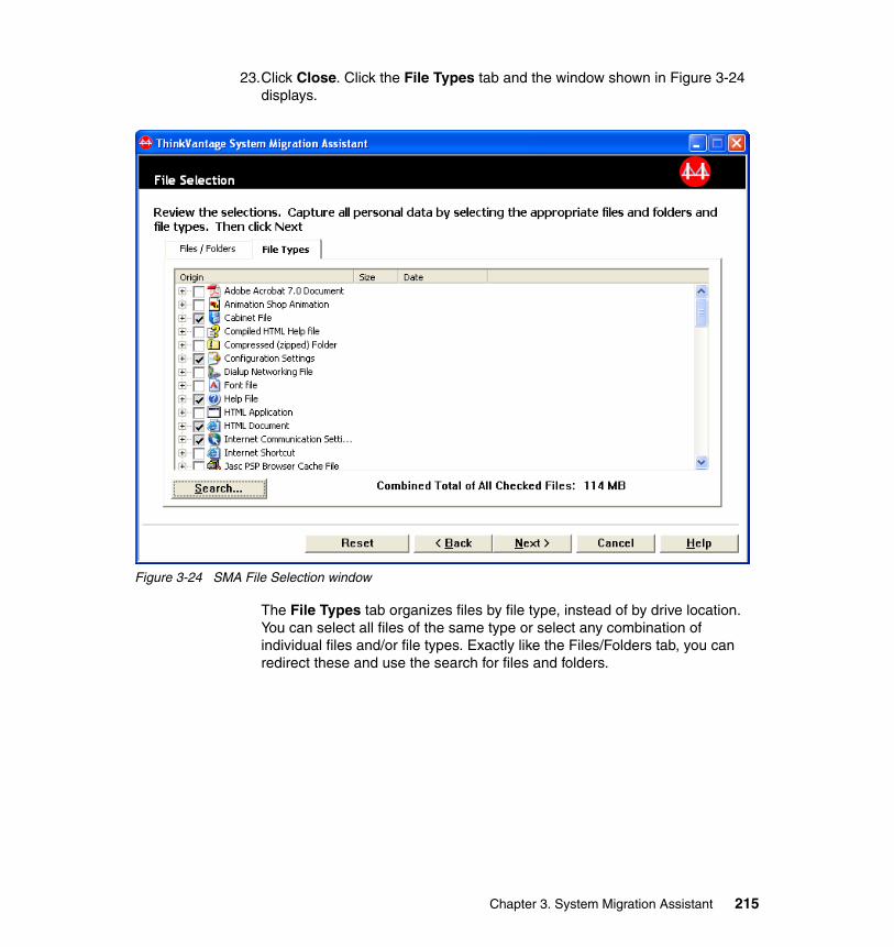
23.Click Close. Click the File Types tab and the window shown in Figure 3-24 displays.
Figure 3-24 SMA File Selection window
The File Types tab organizes files by file type, instead of by drive location. You can select all files of the same type or select any combination of individual files and/or file types. Exactly like the Files/Folders tab, you can redirect these and use the search for files and folders.
Chapter 3. System Migration Assistant 215
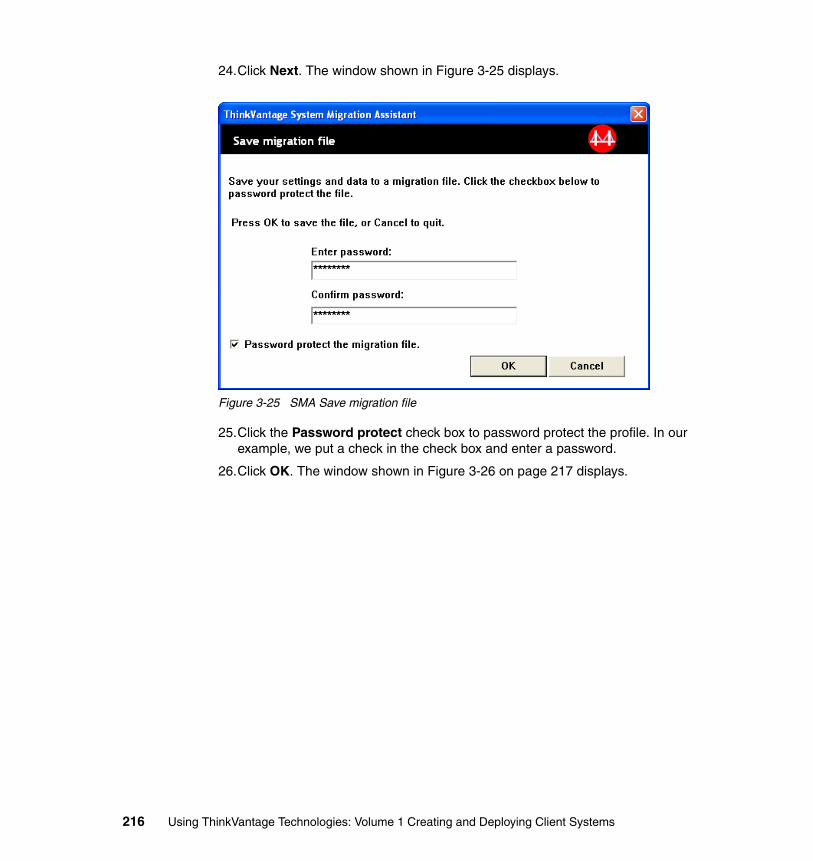
24.Click Next. The window shown in Figure 3-25 displays.
Figure 3-25 SMA Save migration file
25.Click the Password protect check box to password protect the profile. In our example, we put a check in the check box and enter a password.
26.Click OK. The window shown in Figure 3-26 on page 217 displays.
216 Using ThinkVantage Technologies: Volume 1 Creating and Deploying Client Systems
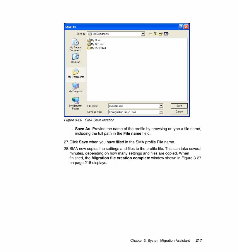
Figure 3-26 SMA Save location
– Save As. Provide the name of the profile by browsing or type a file name, including the full path in the File name field.
27.Click Save when you have filled in the SMA profile File name.
28.SMA now copies the settings and files to the profile file. This can take several minutes, depending on how many settings and files are copied. When finished, the Migration file creation complete window shown in Figure 3-27 on page 218 displays.
Chapter 3. System Migration Assistant 217
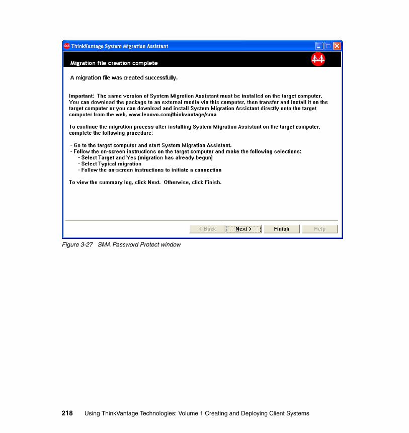
Figure 3-27 SMA Password Protect window
218 Using ThinkVantage Technologies: Volume 1 Creating and Deploying Client Systems
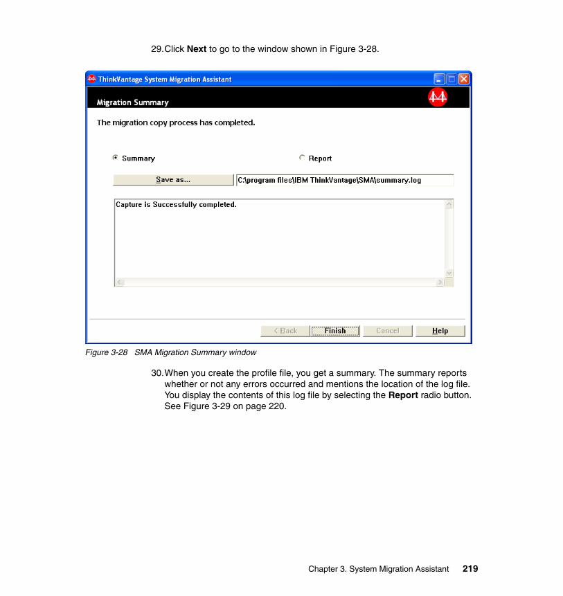
29.Click Next to go to the window shown in Figure 3-28.
Figure 3-28 SMA Migration Summary window
30.When you create the profile file, you get a summary. The summary reports whether or not any errors occurred and mentions the location of the log file. You display the contents of this log file by selecting the Report radio button. See Figure 3-29 on page 220.
Chapter 3. System Migration Assistant 219
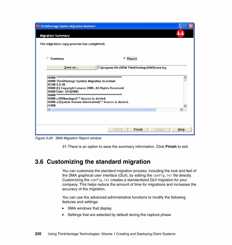
Figure 3-29 SMA Migration Report window
31.There is an option to save the summary information. Click Finish to exit.
3.6 Customizing the standard migrationYou can customize the standard migration process, including the look and feel of the SMA graphical user interface (GUI), by editing the config.ini file directly. Customizing the config.ini creates a standardized GUI migration for your company. This helps reduce the amount of time for migrations and increases the accuracy of the migration.
You can use the advanced administrative functions to modify the following features and settings:
� SMA windows that display
� Settings that are selected by default during the capture phase
220 Using ThinkVantage Technologies: Volume 1 Creating and Deploying Client Systems
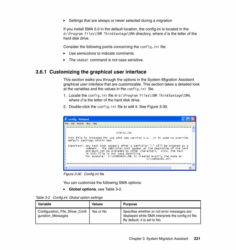
� Settings that are always or never selected during a migration
If you install SMA 5.0 in the default location, the config.ini is located in the d:\Program Files\IBM ThinkVantage\SMA directory, where d is the letter of the hard disk drive.
Consider the following points concerning the config.ini file:
� Use semicolons to indicate comments.
� The smabat command is not case sensitive.
3.6.1 Customizing the graphical user interfaceThis section walks you through the options in the System Migration Assistant graphical user interface that are customizable. This section takes a detailed look at the variables and the values in the config.ini file.
1. Locate the config.ini file in d:\Program Files\IBM ThinkVantage\SMA, where d is the letter of the hard disk drive.
2. Double-click the config.ini file to edit it. See Figure 3-30.
Figure 3-30 Config.ini file
You can customize the following SMA options:
� Global options, see Table 3-2.
Table 3-2 Config.ini: Global option settings
Variable Values Purpose
Configuration_File_Show_Configuration_Messages
Yes or No Specifies whether or not error messages are displayed while SMA interprets the config.ini file. By default, it is set to No.
Chapter 3. System Migration Assistant 221
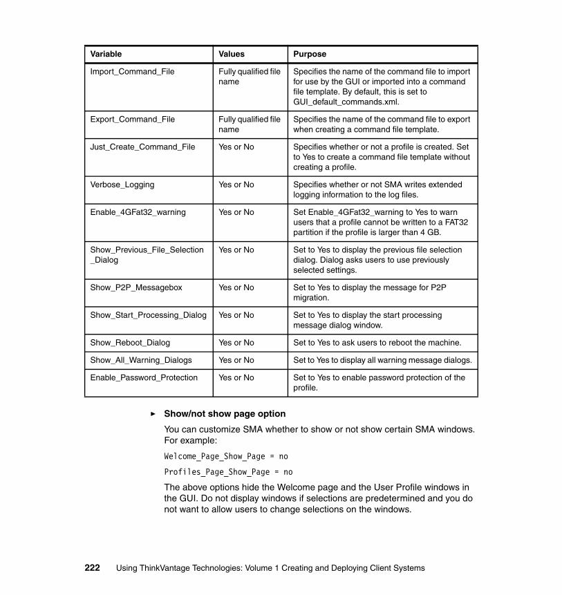
� Show/not show page option
You can customize SMA whether to show or not show certain SMA windows. For example:
Welcome_Page_Show_Page = no
Profiles_Page_Show_Page = no
The above options hide the Welcome page and the User Profile windows in the GUI. Do not display windows if selections are predetermined and you do not want to allow users to change selections on the windows.
Import_Command_File Fully qualified file name
Specifies the name of the command file to import for use by the GUI or imported into a command file template. By default, this is set to GUI_default_commands.xml.
Export_Command_File Fully qualified file name
Specifies the name of the command file to export when creating a command file template.
Just_Create_Command_File Yes or No Specifies whether or not a profile is created. Set to Yes to create a command file template without creating a profile.
Verbose_Logging Yes or No Specifies whether or not SMA writes extended logging information to the log files.
Enable_4GFat32_warning Yes or No Set Enable_4GFat32_warning to Yes to warn users that a profile cannot be written to a FAT32 partition if the profile is larger than 4 GB.
Show_Previous_File_Selection_Dialog
Yes or No Set to Yes to display the previous file selection dialog. Dialog asks users to use previously selected settings.
Show_P2P_Messagebox Yes or No Set to Yes to display the message for P2P migration.
Show_Start_Processing_Dialog Yes or No Set to Yes to display the start processing message dialog window.
Show_Reboot_Dialog Yes or No Set to Yes to ask users to reboot the machine.
Show_All_Warning_Dialogs Yes or No Set to Yes to display all warning message dialogs.
Enable_Password_Protection Yes or No Set to Yes to enable password protection of the profile.
Variable Values Purpose
222 Using ThinkVantage Technologies: Volume 1 Creating and Deploying Client Systems
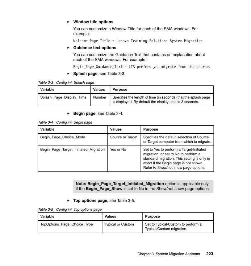
� Window title options
You can customize a Window Title for each of the SMA windows. For example:
Welcome_Page_Title = Lenovo Training Solutions System Migration
� Guidance text options
You can customize the Guidance Text that contains an explanation about each of the SMA windows. For example:
Begin_Page_Guidance_Text = LTS prefers you migrate from the source.
� Splash page, see Table 3-3.
Table 3-3 Config.ini: Splash page
� Begin page, see Table 3-4.
Table 3-4 Config.ini: Begin page
� Top options page, see Table 3-5.
Table 3-5 Config.ini: Top options page
Variable Values Purpose
Splash_Page_Display_Time Number Specifies the length of time (in seconds) that the splash page is displayed. By default the display time is 3 seconds.
Variable Values Purpose
Begin_Page_Choice_Mode Source or Target Specifies the default selection of Source or Target computer from which to migrate.
Begin_Page_Target_Initiated_Migration Yes or No Set to Yes to perform a Target-Initiated migration, or set to No to perform a standard migration. This setting is only in effect if the Begin page is not shown. Refer to Show/not show page options.
Note: Begin_Page_Target_Initiated_Migration option is applicable only if the Begin_Page_Show is set to No in the Show/not show page options.
Variable Values Purpose
TopOptions_Page_Choice_Type Typical or Custom Set to Typical/Custom to perform a Typical/Custom migration.
Chapter 3. System Migration Assistant 223
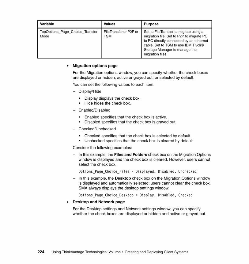
� Migration options page
For the Migration options window, you can specify whether the check boxes are displayed or hidden, active or grayed out, or selected by default.
You can set the following values to each item:
– Display/Hide
• Display displays the check box.• Hide hides the check box.
– Enabled/Disabled
• Enabled specifies that the check box is active.• Disabled specifies that the check box is grayed out.
– Checked/Unchecked
• Checked specifies that the check box is selected by default.• Unchecked specifies that the check box is cleared by default.
Consider the following examples:
– In this example, the Files and Folders check box on the Migration Options window is displayed and the check box is cleared. However, users cannot select the check box.
Options_Page_Choice_Files = Displayed, Disabled, Unchecked
– In this example, the Desktop check box on the Migration Options window is displayed and automatically selected; users cannot clear the check box. SMA always displays the desktop settings window.
Options_Page_Choice_Desktop = Display, Disabled, Checked
� Desktop and Network page
For the Desktop settings and Network settings window, you can specify whether the check boxes are displayed or hidden and active or grayed out.
TopOptions_Page_Choice_TransferMode
FileTransfer or P2P or TSM
Set to FileTransfer to migrate using a migration file. Set to P2P to migrate PC to PC directly connected by an ethernet cable. Set to TSM to use IBM Tivoli® Storage Manager to manage the migration files.
Variable Values Purpose
224 Using ThinkVantage Technologies: Volume 1 Creating and Deploying Client Systems
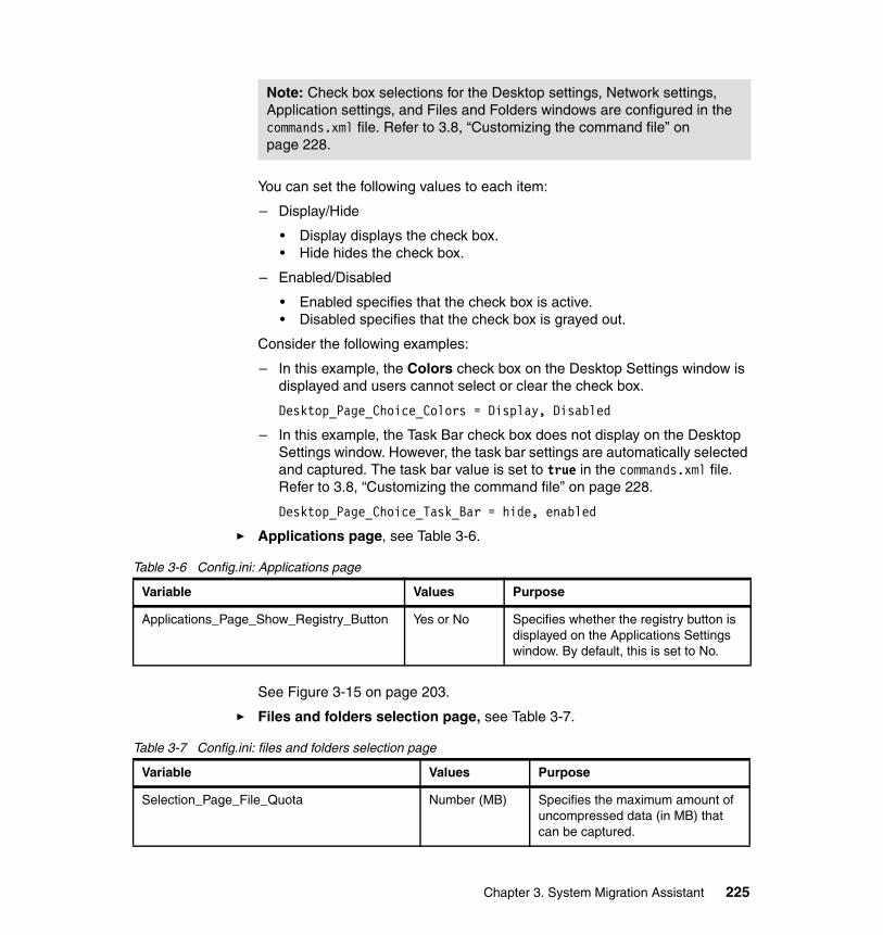
You can set the following values to each item:
– Display/Hide
• Display displays the check box.• Hide hides the check box.
– Enabled/Disabled
• Enabled specifies that the check box is active.• Disabled specifies that the check box is grayed out.
Consider the following examples:
– In this example, the Colors check box on the Desktop Settings window is displayed and users cannot select or clear the check box.
Desktop_Page_Choice_Colors = Display, Disabled
– In this example, the Task Bar check box does not display on the Desktop Settings window. However, the task bar settings are automatically selected and captured. The task bar value is set to true in the commands.xml file. Refer to 3.8, “Customizing the command file” on page 228.
Desktop_Page_Choice_Task_Bar = hide, enabled
� Applications page, see Table 3-6.
Table 3-6 Config.ini: Applications page
See Figure 3-15 on page 203.
� Files and folders selection page, see Table 3-7.
Table 3-7 Config.ini: files and folders selection page
Note: Check box selections for the Desktop settings, Network settings, Application settings, and Files and Folders windows are configured in the commands.xml file. Refer to 3.8, “Customizing the command file” on page 228.
Variable Values Purpose
Applications_Page_Show_Registry_Button Yes or No Specifies whether the registry button is displayed on the Applications Settings window. By default, this is set to No.
Variable Values Purpose
Selection_Page_File_Quota Number (MB) Specifies the maximum amount of uncompressed data (in MB) that can be captured.
Chapter 3. System Migration Assistant 225
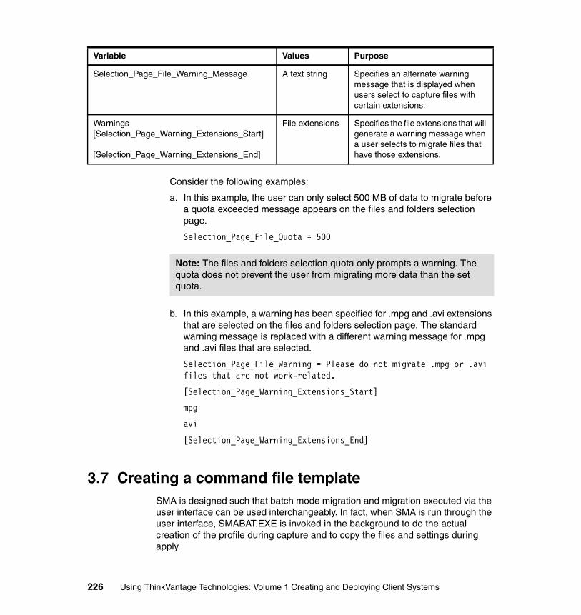
Consider the following examples:
a. In this example, the user can only select 500 MB of data to migrate before a quota exceeded message appears on the files and folders selection page.
Selection_Page_File_Quota = 500
b. In this example, a warning has been specified for .mpg and .avi extensions that are selected on the files and folders selection page. The standard warning message is replaced with a different warning message for .mpg and .avi files that are selected.
Selection_Page_File_Warning = Please do not migrate .mpg or .avi files that are not work-related.
[Selection_Page_Warning_Extensions_Start]
mpg
avi
[Selection_Page_Warning_Extensions_End]
3.7 Creating a command file template SMA is designed such that batch mode migration and migration executed via the user interface can be used interchangeably. In fact, when SMA is run through the user interface, SMABAT.EXE is invoked in the background to do the actual creation of the profile during capture and to copy the files and settings during apply.
Selection_Page_File_Warning_Message A text string Specifies an alternate warning message that is displayed when users select to capture files with certain extensions.
Warnings[Selection_Page_Warning_Extensions_Start]
[Selection_Page_Warning_Extensions_End]
File extensions Specifies the file extensions that will generate a warning message when a user selects to migrate files that have those extensions.
Variable Values Purpose
Note: The files and folders selection quota only prompts a warning. The quota does not prevent the user from migrating more data than the set quota.
226 Using ThinkVantage Technologies: Volume 1 Creating and Deploying Client Systems
One advantage of this design is that the profiles produced in either mode are the same. For instance, if you at one point created a profile in batch mode but at a later time are uncertain about the settings and files captured, you can open the profile and examine its contents through the user interface.
Another advantage of this design is that you can use the user interface to create a command file template for use in batch mode. Rather than creating an actual profile, SMA is run through the user interface to capture the types of settings you want to capture. This information is written to a command file, which you can then use to capture a profile in batch mode. In other words, you can create this template file once, and then use it repeatedly to capture actual settings of different source computers. Although the specific settings that you migrate depend on the source computers’ environment, the kind of settings that you migrate will be the same across your entire organization. File migration information is not written to this template, because file handling is driven differently in the two modes. To create a command file template, follow these steps:
1. Log on to the system as the appropriate user with administrative privileges.
2. Click Start → Run, enter:
d:\Program Files\IBM ThinkVantage\SMA\config.ini and click OK, where d is the letter of the hard disk drive.
3. Scroll down in the config.ini to the Global Options section and change the following to match the below settings:
Export_Command_File = C:\commands.xml
Just_Create_Command_File = yes
4. The Export_Command_File option creates a command file template in the location you specify.
5. Close and save the new config.ini file.
6. Start SMA.EXE and run the capture phase. Make the selections for each page as you want them to appear in the command file template.
7. The Save Migration File window captures the location and name of the profile in the template file, although no actual profile is created.
8. Edit the d:\Program Files\IBM ThinkVantage\SMA\config.ini file and change the Export_Command_File and Just_Create_Command_File
Note: The Import_Command_File option imports the data from another command file into the command file template you create. This is beneficial if an existing command file already has files and folders selections that the new template needs.
Chapter 3. System Migration Assistant 227
variable back to unspecified. This prevents your template file from being overwritten the next time you run SMA.
9. Now you are ready to add specific file inclusion and exclusion routines by editing your template file. Find more information about editing the command file in the next subject, Customizing the command file.
3.8 Customizing the command fileDuring the capture phase, SMA reads the contents of the command file and archives settings and data. This section contains information about command files, the statements they contain, and examples you can use. You can find an implementation scenario in 3.11, “System Migration Assistant migration scenario” on page 248.
System Migration Assistant provides a default command file for you to use (GUI_default_commands.xml) as a template to create a customized command file. Also, you can create your own template by following the steps in 3.7, “Creating a command file template” on page 226.
Consider the following points concerning SMA 5.0 command files:
� The command file follows XML version 1.0 syntax.
� The command file is case sensitive.
� Each command and parameter section must start with <TagName> and end with </TagName>, and its value must be described between those tags.
� Syntax errors may cause an error when you run SMA. If SMA encounters an error, it writes the error to the log file and continues the operation. Depending on the severity of the error, this can cause flawed results.
3.8.1 Command file parametersThe following contains information about the commands and several examples, with the exception of those concerning file migration or the registry, that you can use in a command file. For more information about the settings that the command file migrates, refer to 3.5.1, “Capturing settings and files” on page 193.
Note: System Migration Assistant 5.0 uses XML technology to describe its command file commands.
228 Using ThinkVantage Technologies: Volume 1 Creating and Deploying Client Systems
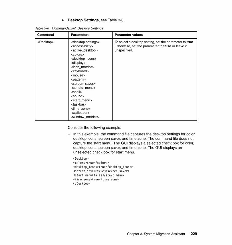
� Desktop Settings, see Table 3-8.
Table 3-8 Commands.xml: Desktop Settings
Consider the following example:
– In this example, the command file captures the desktop settings for color, desktop icons, screen saver, and time zone. The command file does not capture the start menu. The GUI displays a selected check box for color, desktop icons, screen saver, and time zone. The GUI displays an unselected check box for start menu.
<Desktop><colors>true</colors><desktop_icons>true</desktop_icons><screen_saver>true</screen_saver><start_menu>false</start_menu><time_zone>true</time_zone></Desktop>
Command Parameters Parameter values
<Desktop> <desktop settings><accessibility><active_desktop><colors><desktop_icons><display><icon_metrics><keyboard><mouse><pattern><screen_saver><sendto_menu><shell><sound><start_menu><taskbar><time_zone><wallpaper><window_metrics>
To select a desktop setting, set the parameter to true. Otherwise, set the parameter to false or leave it unspecified.
Chapter 3. System Migration Assistant 229
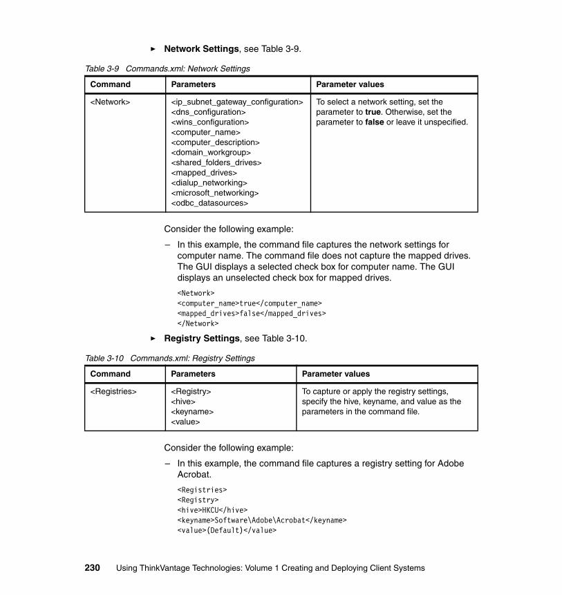
� Network Settings, see Table 3-9.
Table 3-9 Commands.xml: Network Settings
Consider the following example:
– In this example, the command file captures the network settings for computer name. The command file does not capture the mapped drives. The GUI displays a selected check box for computer name. The GUI displays an unselected check box for mapped drives.
<Network><computer_name>true</computer_name><mapped_drives>false</mapped_drives></Network>
� Registry Settings, see Table 3-10.
Table 3-10 Commands.xml: Registry Settings
Consider the following example:
– In this example, the command file captures a registry setting for Adobe Acrobat.
<Registries><Registry><hive>HKCU</hive><keyname>Software\Adobe\Acrobat</keyname><value>(Default)</value>
Command Parameters Parameter values
<Network> <ip_subnet_gateway_configuration><dns_configuration><wins_configuration><computer_name><computer_description><domain_workgroup><shared_folders_drives><mapped_drives><dialup_networking><microsoft_networking><odbc_datasources>
To select a network setting, set the parameter to true. Otherwise, set the parameter to false or leave it unspecified.
Command Parameters Parameter values
<Registries> <Registry><hive><keyname><value>
To capture or apply the registry settings, specify the hive, keyname, and value as the parameters in the command file.
230 Using ThinkVantage Technologies: Volume 1 Creating and Deploying Client Systems
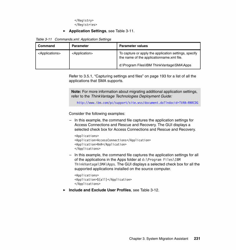
</Registry></Registries>
� Application Settings, see Table 3-11.
Table 3-11 Commands.xml: Application Settings
Refer to 3.5.1, “Capturing settings and files” on page 193 for a list of all the applications that SMA supports.
Consider the following examples:
– In this example, the command file captures the application settings for Access Connections and Rescue and Recovery. The GUI displays a selected check box for Access Connections and Rescue and Recovery.
<Applications><Application>AccessConnections</Application><Application>RnR</Application></Applications>
– In this example, the command file captures the application settings for all of the applications in the Apps folder at d:\Program Files\IBM ThinkVantage\SMA\Apps. The GUI displays a selected check box for all the supported applications installed on the source computer.
<Applications><Application>$(all)</Application></Applications>
� Include and Exclude User Profiles, see Table 3-12.
Command Parameter Parameter values
<Applications> <Application> To capture or apply the application settings, specify the name of the applicationname.xml file.
d:\Program Files\IBM ThinkVantage\SMA\Apps
Note: For more information about migrating additional application settings, refer to the ThinkVantage Technologies Deployment Guide:
http://www.ibm.com/pc/support/site.wss/document.do?lndocid=TVAN-RNRCDG
Chapter 3. System Migration Assistant 231
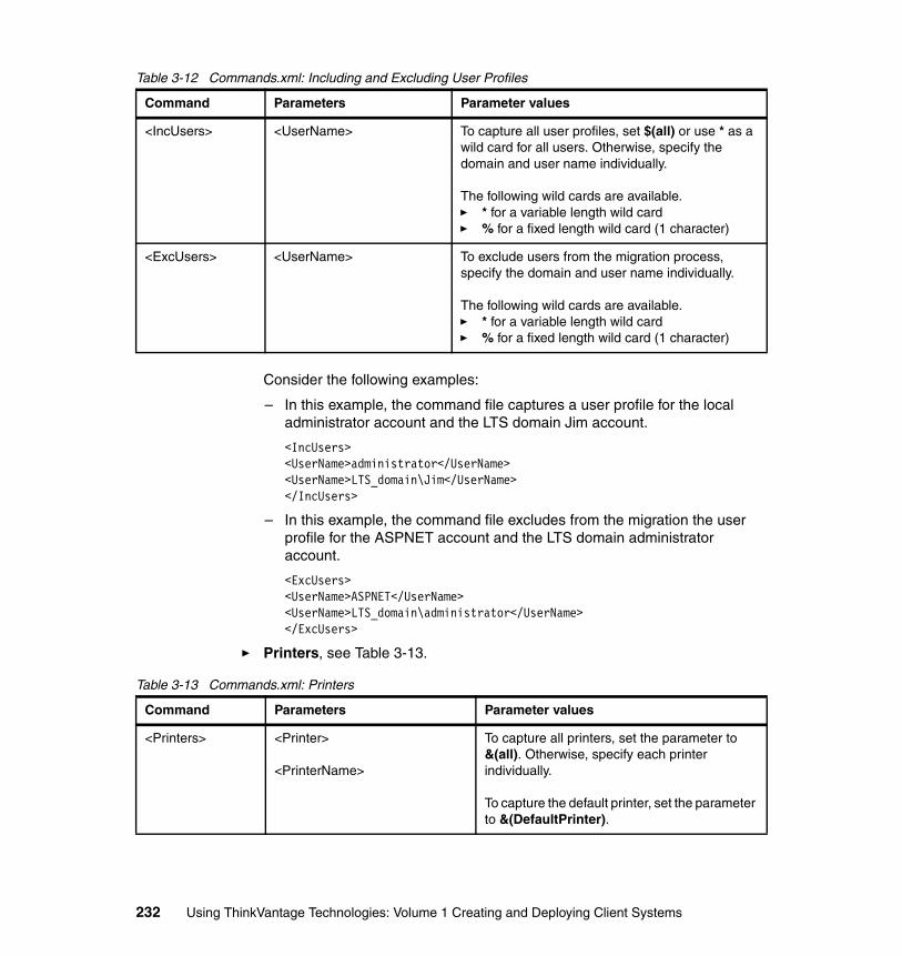
Table 3-12 Commands.xml: Including and Excluding User Profiles
Consider the following examples:
– In this example, the command file captures a user profile for the local administrator account and the LTS domain Jim account.
<IncUsers><UserName>administrator</UserName><UserName>LTS_domain\Jim</UserName></IncUsers>
– In this example, the command file excludes from the migration the user profile for the ASPNET account and the LTS domain administrator account.
<ExcUsers><UserName>ASPNET</UserName><UserName>LTS_domain\administrator</UserName></ExcUsers>
� Printers, see Table 3-13.
Table 3-13 Commands.xml: Printers
Command Parameters Parameter values
<IncUsers> <UserName> To capture all user profiles, set $(all) or use * as a wild card for all users. Otherwise, specify the domain and user name individually.
The following wild cards are available.� * for a variable length wild card� % for a fixed length wild card (1 character)
<ExcUsers> <UserName> To exclude users from the migration process, specify the domain and user name individually.
The following wild cards are available.� * for a variable length wild card� % for a fixed length wild card (1 character)
Command Parameters Parameter values
<Printers> <Printer>
<PrinterName>
To capture all printers, set the parameter to &(all). Otherwise, specify each printer individually.
To capture the default printer, set the parameter to &(DefaultPrinter).
232 Using ThinkVantage Technologies: Volume 1 Creating and Deploying Client Systems
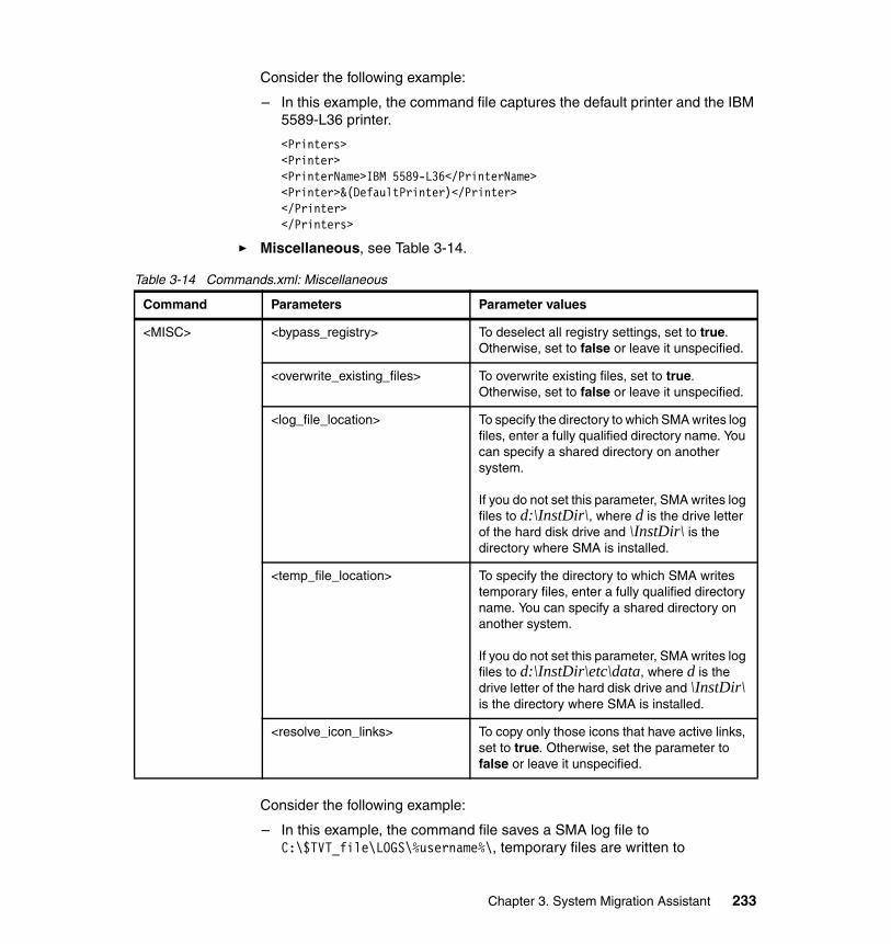
Consider the following example:
– In this example, the command file captures the default printer and the IBM 5589-L36 printer.
<Printers><Printer><PrinterName>IBM 5589-L36</PrinterName><Printer>&(DefaultPrinter)</Printer></Printer></Printers>
� Miscellaneous, see Table 3-14.
Table 3-14 Commands.xml: Miscellaneous
Consider the following example:
– In this example, the command file saves a SMA log file to C:\$TVT_file\LOGS\%username%\, temporary files are written to
Command Parameters Parameter values
<MISC> <bypass_registry> To deselect all registry settings, set to true. Otherwise, set to false or leave it unspecified.
<overwrite_existing_files> To overwrite existing files, set to true. Otherwise, set to false or leave it unspecified.
<log_file_location> To specify the directory to which SMA writes log files, enter a fully qualified directory name. You can specify a shared directory on another system.
If you do not set this parameter, SMA writes log files to d:\InstDir\, where d is the drive letter of the hard disk drive and \InstDir\ is the directory where SMA is installed.
<temp_file_location> To specify the directory to which SMA writes temporary files, enter a fully qualified directory name. You can specify a shared directory on another system.
If you do not set this parameter, SMA writes log files to d:\InstDir\etc\data, where d is the drive letter of the hard disk drive and \InstDir\ is the directory where SMA is installed.
<resolve_icon_links> To copy only those icons that have active links, set to true. Otherwise, set the parameter to false or leave it unspecified.
Chapter 3. System Migration Assistant 233
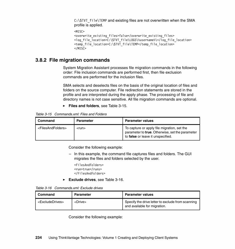
C:\$TVT_file\TEMP and existing files are not overwritten when the SMA profile is applied.
<MISC><overwrite_existing_files>false</overwrite_existing_files><log_file_location>C:\$TVT_file\LOGS\%username%\</log_file_location><temp_file_location>C:\$TVT_file\TEMP</temp_file_location></MISC>
3.8.2 File migration commandsSystem Migration Assistant processes file migration commands in the following order: File inclusion commands are performed first, then file exclusion commands are performed for the inclusion files.
SMA selects and deselects files on the basis of the original location of files and folders on the source computer. File redirection statements are stored in the profile and are interpreted during the apply phase. The processing of file and directory names is not case sensitive. All file migration commands are optional.
� Files and folders, see Table 3-15.
Table 3-15 Commands.xml: Files and Folders
Consider the following example:
– In this example, the command file captures files and folders. The GUI migrates the files and folders selected by the user.
<FilesAndFolders><run>true</runs></FilesAndFolders>
� Exclude drives, see Table 3-16.
Table 3-16 Commands.xml: Exclude drives
Consider the following example:
Command Parameter Parameter values
<FilesAndFolders> <run> To capture or apply file migration, set the parameter to true. Otherwise, set the parameter to false or leave it unspecified.
Command Parameter Parameter values
<ExcludeDrives> <Drive> Specify the drive letter to exclude from scanning and available for migration.
234 Using ThinkVantage Technologies: Volume 1 Creating and Deploying Client Systems
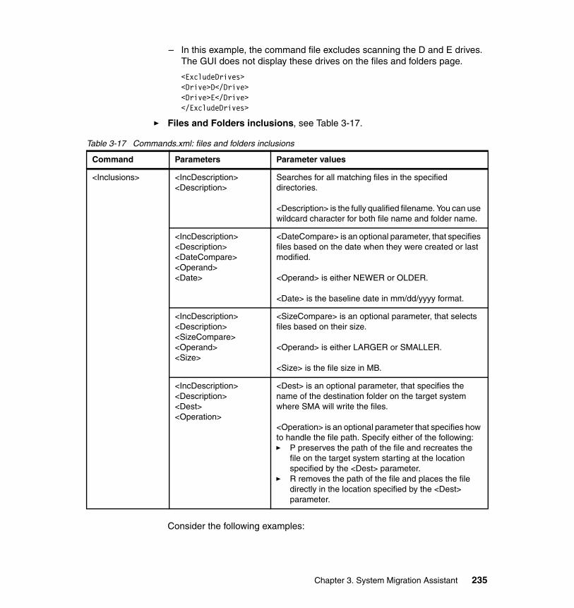
– In this example, the command file excludes scanning the D and E drives. The GUI does not display these drives on the files and folders page.
<ExcludeDrives><Drive>D</Drive><Drive>E</Drive></ExcludeDrives>
� Files and Folders inclusions, see Table 3-17.
Table 3-17 Commands.xml: files and folders inclusions
Consider the following examples:
Command Parameters Parameter values
<Inclusions> <IncDescription><Description>
Searches for all matching files in the specified directories.
<Description> is the fully qualified filename. You can use wildcard character for both file name and folder name.
<IncDescription><Description><DateCompare><Operand><Date>
<DateCompare> is an optional parameter, that specifies files based on the date when they were created or last modified.
<Operand> is either NEWER or OLDER.
<Date> is the baseline date in mm/dd/yyyy format.
<IncDescription><Description><SizeCompare><Operand><Size>
<SizeCompare> is an optional parameter, that selects files based on their size.
<Operand> is either LARGER or SMALLER.
<Size> is the file size in MB.
<IncDescription><Description><Dest><Operation>
<Dest> is an optional parameter, that specifies the name of the destination folder on the target system where SMA will write the files.
<Operation> is an optional parameter that specifies how to handle the file path. Specify either of the following:� P preserves the path of the file and recreates the
file on the target system starting at the location specified by the <Dest> parameter.
� R removes the path of the file and places the file directly in the location specified by the <Dest> parameter.
Chapter 3. System Migration Assistant 235
– In this example, the command file includes all Microsoft Word .doc files in the MyWorkFolder folder. SMA will migrate all of the files to the $Migrate folder. SMA removes the path of the files and places the files directly into the $Migrate folder.
<Inclusions><IncDescription><Description>C:\MyWorkFolder\*.doc</Description><Dest>C:\$Migrate</Dest><Operation>r</Operation></IncDescription></Inclusions>
– In this example, the command file includes all of the files in the MyWorkFolder folder. To be included in the migration, these files must have been created after 07/31/2005.
<Inclusions><IncDescription><Description>C:\MyWorkFolder\*.*</Description><DateCompare><Operand>NEWER</Operand><Date>07/31/2005</Date></DateCompare></IncDescription></Inclusions>
� files and folders exclusions, see Table 3-18 on page 237.
236 Using ThinkVantage Technologies: Volume 1 Creating and Deploying Client Systems
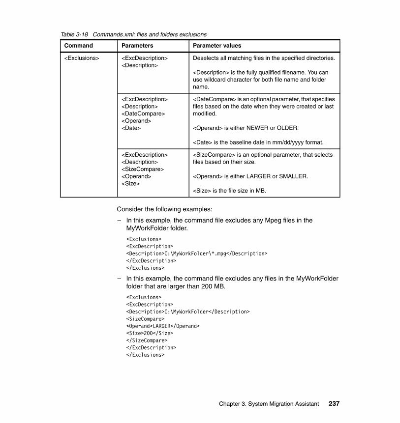
Table 3-18 Commands.xml: files and folders exclusions
Consider the following examples:
– In this example, the command file excludes any Mpeg files in the MyWorkFolder folder.
<Exclusions><ExcDescription><Description>C:\MyWorkFolder\*.mpg</Description></ExcDescription></Exclusions>
– In this example, the command file excludes any files in the MyWorkFolder folder that are larger than 200 MB.
<Exclusions><ExcDescription><Description>C:\MyWorkFolder</Description><SizeCompare><Operand>LARGER</Operand><Size>200</Size></SizeCompare></ExcDescription></Exclusions>
Command Parameters Parameter values
<Exclusions> <ExcDescription><Description>
Deselects all matching files in the specified directories.
<Description> is the fully qualified filename. You can use wildcard character for both file name and folder name.
<ExcDescription><Description><DateCompare><Operand><Date>
<DateCompare> is an optional parameter, that specifies files based on the date when they were created or last modified.
<Operand> is either NEWER or OLDER.
<Date> is the baseline date in mm/dd/yyyy format.
<ExcDescription><Description><SizeCompare><Operand><Size>
<SizeCompare> is an optional parameter, that selects files based on their size.
<Operand> is either LARGER or SMALLER.
<Size> is the file size in MB.
Chapter 3. System Migration Assistant 237
3.8.3 Examples of file migration commandsThis section contains three examples of code used to select files during the capture phase.
Example one The following code example selects all files with a .pdf extension (Adobe Acrobat documents) and relocates them in the D:\My Work directory. It then excludes all files that are in the D:\No_Longer_Used directory.
<Inclusions><IncDescription><Description>*:\*.pdf /s</Description><Dest>D:\My Work</Dest><Operation>r</Operation></IncDescription></Inclusions><Exclusions><ExcDescription><Description>D:\No_Longer_Used\</Description></ExcDescription></Exclusions>
Example twoThe following code example selects the contents of the D drive, excluding the Personal Files folder and all files with a .tmp extension.
<Inclusions><IncDescription><Description>D:\*.* /s</Description></IncDescription></Inclusions><Exclusions><ExcDescription><Description>D:\Personal Files</Description></ExcDescription><ExcDescription><Description>*:\*.tmp /s</Description></ExcDescription></Exclusions>
Example threeThe following code example selects the contents of My Documents for the user profile paths on the system. The code also selects the contents of C:\My Documents. The code then deselects all .vol (Utimaco Private Disk volumes) in My Documents for the user profile paths on the system.
238 Using ThinkVantage Technologies: Volume 1 Creating and Deploying Client Systems
<Inclusions><IncDescription><Description>%userprofile%\My Documents\ /s</Description></IncDescription><IncDescription><Description>c:\My Documents\ /s</Description></IncDescription></Inclusions><Exclusions><ExcDescription><Description>%userprofile%\My Documents\*.vol /s</Description></ExcDescription></Exclusions>
3.8.4 Command file behavior during the apply phaseThe command file that is used during the apply phase has the same syntax as the file used during the capture phase, although some of the commands behave differently. During the apply phase, you can only make changes to a given profile. For instance, if your profile includes all desktop settings but you do not want to apply the active desktop to a given target computer, you can deselect that option by typing <active_desktop>false</active_desktop> in the desktop settings section of the command file. However, if your profile does not include printer settings, you cannot include printer settings by entering <printer>$(all)</printer> in the printer settings section of the command file. In order for deselection to be successful, you must know which settings were stored in the profile.
Similarly, when the profile includes a selection of files, you can exclude some or all, but you cannot select a file that is not included in the profile. In order for deselection to be successful, you must know which files are in the profile, because this information is not readily available in the original command file. Remember that SMA processes file exclusion commands assuming the original location of files and folders on the source computer prior to interpreting redirection statements.
During copying, when SMA relocates a file to a folder that already has a file with that name, the base name of the to-be-relocated file is appended with _01 if the <overwrite_existing_files> parameter in the command file is set to not overwriting. For example, the file sample.txt will be renamed sample_01.txt. Additional duplicate files will be given the addition _02, _03, and so forth.
During the apply phase, these commands exhibit special behavior:
� <ExcludeDrives> This command is ignored.
� <Misc>
Chapter 3. System Migration Assistant 239

<bypass_registry> Enter true to deselect all registry settings. Otherwise, enter false or leave it unspecified.
3.9 Performing a SMA administrative installationThis section describes how to perform an administrative installation of SMA. An IT person can create a standardized migration using the administrative installation with customized System Migration Assistant files.
� An administrative installation involves extracting the SMA program files and the Microsoft InstallShield package (MSI).
� Next, inserting the customized config.ini, commands.xml, and any application.xml files in the appropriate location.
� Finally, an unattended installation of the SMA files with the customized GUI and command file.
3.9.1 Extracting SMAsetup.exeTo do an administrative extraction of SMAsetup.exe, follow these steps:
1. Log on to the computer, using an operating system account with administrative privileges.
2. Open a command prompt. Go to the directory that contains the SMAsetup.exe. To find this file, refer to 3.3.1, “Extracting the System Migration Assistant executable” on page 186.
3. At the command prompt, type the following command:
SMAsetup.exe /a
4. Press Enter to prepare for an administrative installation via a Microsoft InstallShield package (MSI). See Figure 3-32 on page 241.
240 Using ThinkVantage Technologies: Volume 1 Creating and Deploying Client Systems
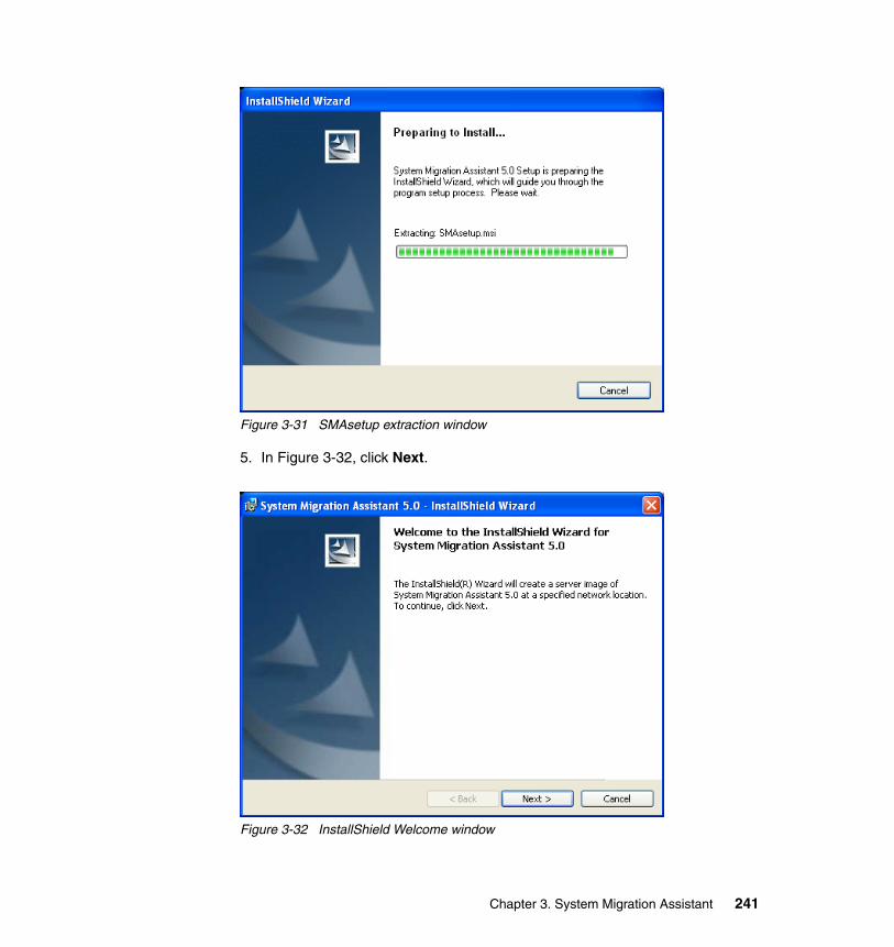
Figure 3-31 SMAsetup extraction window
5. In Figure 3-32, click Next.
Figure 3-32 InstallShield Welcome window
Chapter 3. System Migration Assistant 241
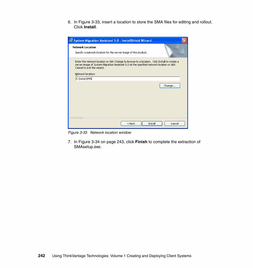
6. In Figure 3-33, insert a location to store the SMA files for editing and rollout. Click Install.
Figure 3-33 Network location window
7. In Figure 3-34 on page 243, click Finish to complete the extraction of SMAsetup.exe.
242 Using ThinkVantage Technologies: Volume 1 Creating and Deploying Client Systems
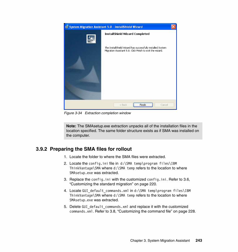
Figure 3-34 Extraction completion window
3.9.2 Preparing the SMA files for rollout1. Locate the folder to where the SMA files were extracted.
2. Locate the config.ini file in d:\SMA temp\program files\IBM ThinkVantage\SMA where d:\SMA temp refers to the location to where SMAsetup.exe was extracted.
3. Replace the config.ini with the customized config.ini. Refer to 3.6, “Customizing the standard migration” on page 220.
4. Locate GUI_default_commands.xml in d:\SMA temp\program files\IBM ThinkVantage\SMA where d:\SMA temp refers to the location to where SMAsetup.exe was extracted.
5. Delete GUI_default_commands.xml and replace it with the customized commands.xml. Refer to 3.8, “Customizing the command file” on page 228.
Note: The SMAsetup.exe extraction unpacks all of the installation files in the location specified. The same folder structure exists as if SMA was installed on the computer.
Chapter 3. System Migration Assistant 243
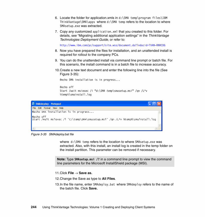
6. Locate the folder for application.xmls in d:\SMA temp\program files\IBM ThinkVantage\SMA\apps where d:\SMA temp refers to the location to where SMAsetup.exe was extracted.
7. Copy any customized application.xml that you created to this folder. For details, see “Migrating additional application settings” in the ThinkVantage Technologies Deployment Guide, or refer to:
http://www.ibm.com/pc/support/site.wss/document.do?lndocid=TVAN-RNRCDG
8. Now you have prepared the files for installation, and an unattended install is required for rollout to the company PCs.
9. You can do the unattended install via command line prompt or batch file. For this scenario, the install command is in a batch file to increase accuracy.
10.Create a new text document and enter the following line into the file (See Figure 3-35):
@echo SMA installation is in progress...
@echo offStart /wait msiexec /i “d:\SMA temp\smasetup.msi” /qn /L*v %temp%\smainstall.log
Figure 3-35 SMAdeploy.bat file
where d:\SMA temp refers to the location to where SMAsetup.exe was extracted. Also, with this install, an install log is created in the temp folder on the install partition. This parameter can be removed if necessary.
11.Click File → Save as.
12.Change the Save as type to All Files.
13.In the file name, enter SMAdeploy.bat where SMAdeploy refers to the name of the batch file. Click Save.
Note: Type SMAsetup.msi /? in a command line prompt to view the command line parameters for the Microsoft InstallShield package (MSI).
244 Using ThinkVantage Technologies: Volume 1 Creating and Deploying Client Systems
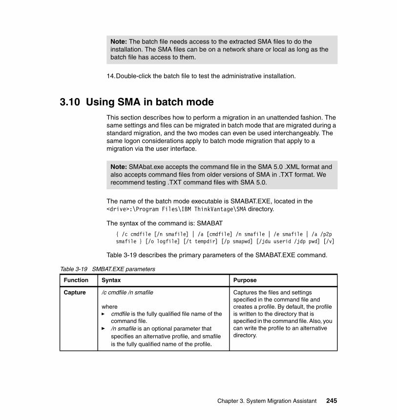
14.Double-click the batch file to test the administrative installation.
3.10 Using SMA in batch modeThis section describes how to perform a migration in an unattended fashion. The same settings and files can be migrated in batch mode that are migrated during a standard migration, and the two modes can even be used interchangeably. The same logon considerations apply to batch mode migration that apply to a migration via the user interface.
The name of the batch mode executable is SMABAT.EXE, located in the <drive>:\Program Files\IBM ThinkVantage\SMA directory.
The syntax of the command is: SMABAT
{ /c cmdfile [/n smafile] | /a [cmdfile] /n smafile | /e smafile | /a /p2p smafile } [/o logfile] [/t tempdir] [/p smapwd] [/jdu userid /jdp pwd] [/v]
Table 3-19 describes the primary parameters of the SMABAT.EXE command.
Table 3-19 SMBAT.EXE parameters
Note: The batch file needs access to the extracted SMA files to do the installation. The SMA files can be on a network share or local as long as the batch file has access to them.
Note: SMAbat.exe accepts the command file in the SMA 5.0 .XML format and also accepts command files from older versions of SMA in .TXT format. We recommend testing .TXT command files with SMA 5.0.
Function Syntax Purpose
Capture /c cmdfile /n smafile
where� cmdfile is the fully qualified file name of the
command file.� /n smafile is an optional parameter that
specifies an alternative profile, and smafile is the fully qualified name of the profile.
Captures the files and settings specified in the command file and creates a profile. By default, the profile is written to the directory that is specified in the command file. Also, you can write the profile to an alternative directory.
Chapter 3. System Migration Assistant 245
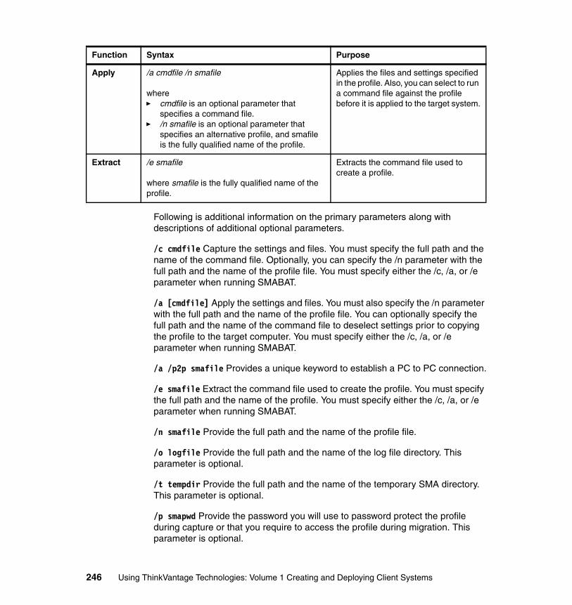
Following is additional information on the primary parameters along with descriptions of additional optional parameters.
/c cmdfile Capture the settings and files. You must specify the full path and the name of the command file. Optionally, you can specify the /n parameter with the full path and the name of the profile file. You must specify either the /c, /a, or /e parameter when running SMABAT.
/a [cmdfile] Apply the settings and files. You must also specify the /n parameter with the full path and the name of the profile file. You can optionally specify the full path and the name of the command file to deselect settings prior to copying the profile to the target computer. You must specify either the /c, /a, or /e parameter when running SMABAT.
/a /p2p smafile Provides a unique keyword to establish a PC to PC connection.
/e smafile Extract the command file used to create the profile. You must specify the full path and the name of the profile. You must specify either the /c, /a, or /e parameter when running SMABAT.
/n smafile Provide the full path and the name of the profile file.
/o logfile Provide the full path and the name of the log file directory. This parameter is optional.
/t tempdir Provide the full path and the name of the temporary SMA directory. This parameter is optional.
/p smapwd Provide the password you will use to password protect the profile during capture or that you require to access the profile during migration. This parameter is optional.
Apply /a cmdfile /n smafile
where� cmdfile is an optional parameter that
specifies a command file.� /n smafile is an optional parameter that
specifies an alternative profile, and smafile is the fully qualified name of the profile.
Applies the files and settings specified in the profile. Also, you can select to run a command file against the profile before it is applied to the target system.
Extract /e smafile
where smafile is the fully qualified name of the profile.
Extracts the command file used to create a profile.
Function Syntax Purpose
246 Using ThinkVantage Technologies: Volume 1 Creating and Deploying Client Systems
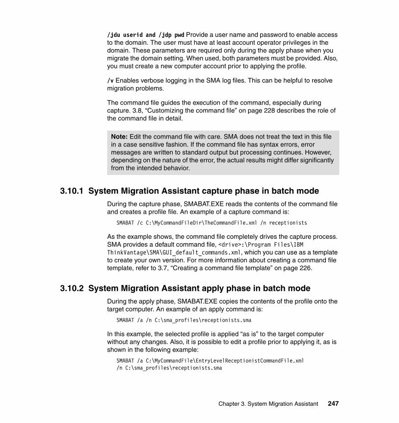
/jdu userid and /jdp pwd Provide a user name and password to enable access to the domain. The user must have at least account operator privileges in the domain. These parameters are required only during the apply phase when you migrate the domain setting. When used, both parameters must be provided. Also, you must create a new computer account prior to applying the profile.
/v Enables verbose logging in the SMA log files. This can be helpful to resolve migration problems.
The command file guides the execution of the command, especially during capture. 3.8, “Customizing the command file” on page 228 describes the role of the command file in detail.
3.10.1 System Migration Assistant capture phase in batch modeDuring the capture phase, SMABAT.EXE reads the contents of the command file and creates a profile file. An example of a capture command is:
SMABAT /c C:\MyCommandFileDir\TheCommandFile.xml /n receptionists
As the example shows, the command file completely drives the capture process. SMA provides a default command file, <drive>:\Program Files\IBM ThinkVantage\SMA\GUI_default_commands.xml, which you can use as a template to create your own version. For more information about creating a command file template, refer to 3.7, “Creating a command file template” on page 226.
3.10.2 System Migration Assistant apply phase in batch mode During the apply phase, SMABAT.EXE copies the contents of the profile onto the target computer. An example of an apply command is:
SMABAT /a /n C:\sma_profiles\receptionists.sma
In this example, the selected profile is applied “as is” to the target computer without any changes. Also, it is possible to edit a profile prior to applying it, as is shown in the following example:
SMABAT /a C:\MyCommandFile\EntryLevelReceptionistCommandFile.xml /n C:\sma_profiles\receptionists.sma
Note: Edit the command file with care. SMA does not treat the text in this file in a case sensitive fashion. If the command file has syntax errors, error messages are written to standard output but processing continues. However, depending on the nature of the error, the actual results might differ significantly from the intended behavior.
Chapter 3. System Migration Assistant 247
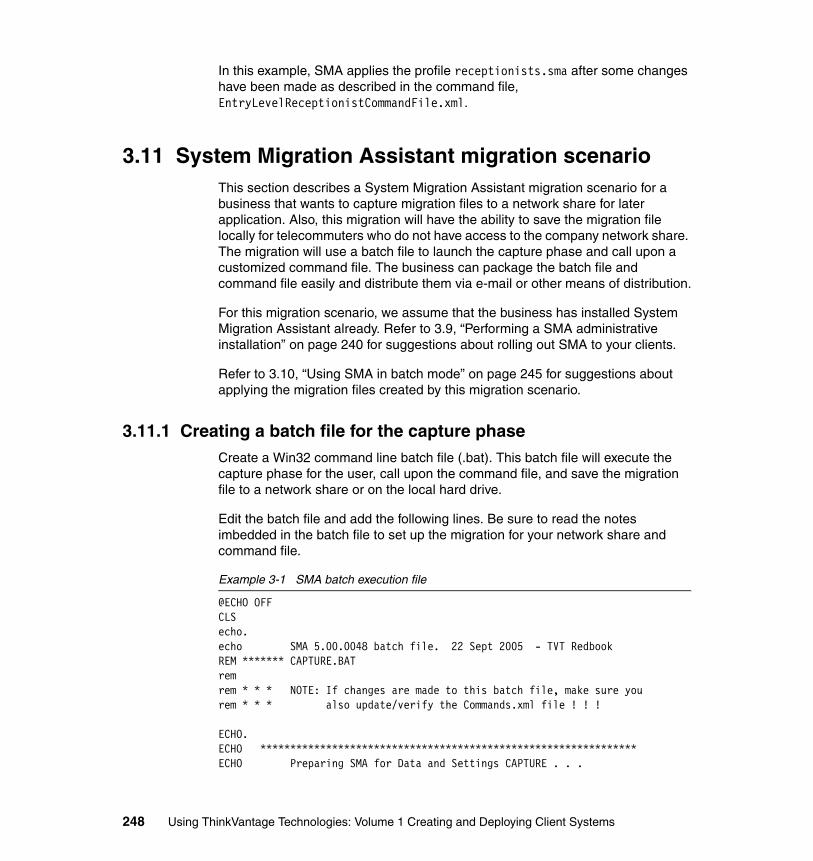
In this example, SMA applies the profile receptionists.sma after some changes have been made as described in the command file, EntryLevelReceptionistCommandFile.xml.
3.11 System Migration Assistant migration scenarioThis section describes a System Migration Assistant migration scenario for a business that wants to capture migration files to a network share for later application. Also, this migration will have the ability to save the migration file locally for telecommuters who do not have access to the company network share. The migration will use a batch file to launch the capture phase and call upon a customized command file. The business can package the batch file and command file easily and distribute them via e-mail or other means of distribution.
For this migration scenario, we assume that the business has installed System Migration Assistant already. Refer to 3.9, “Performing a SMA administrative installation” on page 240 for suggestions about rolling out SMA to your clients.
Refer to 3.10, “Using SMA in batch mode” on page 245 for suggestions about applying the migration files created by this migration scenario.
3.11.1 Creating a batch file for the capture phaseCreate a Win32 command line batch file (.bat). This batch file will execute the capture phase for the user, call upon the command file, and save the migration file to a network share or on the local hard drive.
Edit the batch file and add the following lines. Be sure to read the notes imbedded in the batch file to set up the migration for your network share and command file.
Example 3-1 SMA batch execution file
@ECHO OFFCLSecho.echo SMA 5.00.0048 batch file. 22 Sept 2005 - TVT RedbookREM ******* CAPTURE.BATremrem * * * NOTE: If changes are made to this batch file, make sure yourem * * * also update/verify the Commands.xml file ! ! !
ECHO.ECHO ***************************************************************ECHO Preparing SMA for Data and Settings CAPTURE . . .
248 Using ThinkVantage Technologies: Volume 1 Creating and Deploying Client Systems
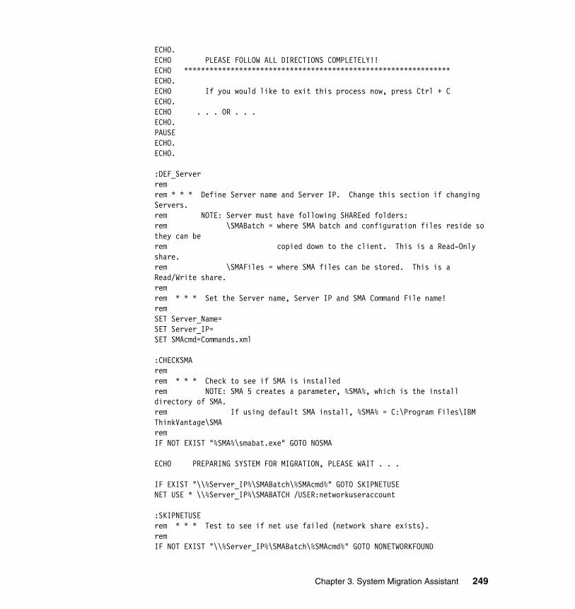
ECHO.ECHO PLEASE FOLLOW ALL DIRECTIONS COMPLETELY!!ECHO ***************************************************************ECHO.ECHO If you would like to exit this process now, press Ctrl + CECHO.ECHO . . . OR . . .ECHO.PAUSEECHO.ECHO.
:DEF_Serverremrem * * * Define Server name and Server IP. Change this section if changing Servers.rem NOTE: Server must have following SHAREed folders:rem \SMABatch = where SMA batch and configuration files reside so they can be rem copied down to the client. This is a Read-Only share.rem \SMAFiles = where SMA files can be stored. This is a Read/Write share.remrem * * * Set the Server name, Server IP and SMA Command File name!remSET Server_Name=SET Server_IP=SET SMAcmd=Commands.xml
:CHECKSMAremrem * * * Check to see if SMA is installedrem NOTE: SMA 5 creates a parameter, %SMA%, which is the install directory of SMA.rem If using default SMA install, %SMA% = C:\Program Files\IBM ThinkVantage\SMAremIF NOT EXIST "%SMA%\smabat.exe" GOTO NOSMA
ECHO PREPARING SYSTEM FOR MIGRATION, PLEASE WAIT . . .
IF EXIST "\\%Server_IP%\SMABatch\%SMAcmd%" GOTO SKIPNETUSENET USE * \\%Server_IP%\SMABATCH /USER:networkuseraccount
:SKIPNETUSErem * * * Test to see if net use failed (network share exists).remIF NOT EXIST "\\%Server_IP%\SMABatch\%SMAcmd%" GOTO NONETWORKFOUND
Chapter 3. System Migration Assistant 249
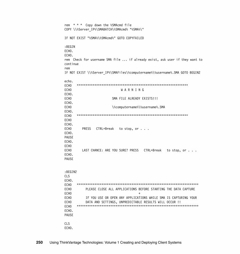
rem * * * Copy down the %SMAcmd fileCOPY \\%Server_IP%\SMABATCH\%SMAcmd% "%SMA%\"
IF NOT EXIST "%SMA%\%SMAcmd%" GOTO COPYFAILED
:BEGINECHO.ECHO.rem Check for username SMA file ... if already exist, ask user if they want to continuerem IF NOT EXIST \\%Server_IP%\SMAFiles\%computername%\%username%.SMA GOTO BEGIN2
echo.ECHO ***************************************************************ECHO W A R N I N GECHO.ECHO SMA FILE ALREADY EXISTS!!!ECHO.ECHO \%computername%\%username%.SMAECHO.ECHO ***************************************************************ECHO ECHO.ECHO PRESS CTRL+Break to stop, or . . .ECHO.PAUSEECHO.ECHO ECHO LAST CHANCE: ARE YOU SURE? PRESS CTRL+Break to stop, or . . .ECHO.PAUSE
:BEGIN2CLSECHO.ECHO *********************************************************************ECHO PLEASE CLOSE ALL APPLICATIONS BEFORE STARTING THE DATA CAPTUREECHO +ECHO IF YOU USE OR OPEN ANY APPLICATIONS WHILE SMA IS CAPTURING YOURECHO DATA AND SETTINGS, UNPREDICTABLE RESULTS WILL OCCUR !!ECHO *********************************************************************ECHO.PAUSE
CLSECHO.
250 Using ThinkVantage Technologies: Volume 1 Creating and Deploying Client Systems
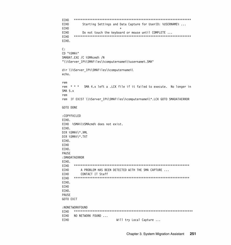
ECHO *********************************************************************ECHO Starting Settings and Data Capture for UserID: %USERNAME% ...ECHO + ECHO Do not touch the keyboard or mouse until COMPLETE ...ECHO *********************************************************************ECHO.
C:CD "%SMA%"SMABAT.EXE /C %SMAcmd% /N "\\%Server_IP%\SMAFiles\%computername%\%username%.SMA"
dir \\%Server_IP%\SMAFiles\%computername%\echo.
remrem * * * SMA 4.x left a .LCK file if it failed to execute. No longer in SMA 5.xremrem IF EXIST \\%Server_IP%\SMAFiles\%computername%\*.LCK GOTO SMADATAERROR
GOTO DONE
:COPYFAILEDECHO.ECHO %SMA%\%SMAcmd% does not exist.ECHO.DIR %SMA%\*.XMLDIR %SMA%\*.TXTECHO.ECHO ECHO.PAUSE:SMADATAERRORECHO.ECHO ********************************************************************ECHO A PROBLEM HAS BEEN DETECTED WITH THE SMA CAPTURE ...ECHO CONTACT IT StaffECHO ********************************************************************ECHO.ECHO ECHO.PAUSEGOTO EXIT
:NONETWORKFOUNDECHO **********************************************************************ECHO NO NETWORK FOUND ... ECHO Will try Local Capture ...
Chapter 3. System Migration Assistant 251
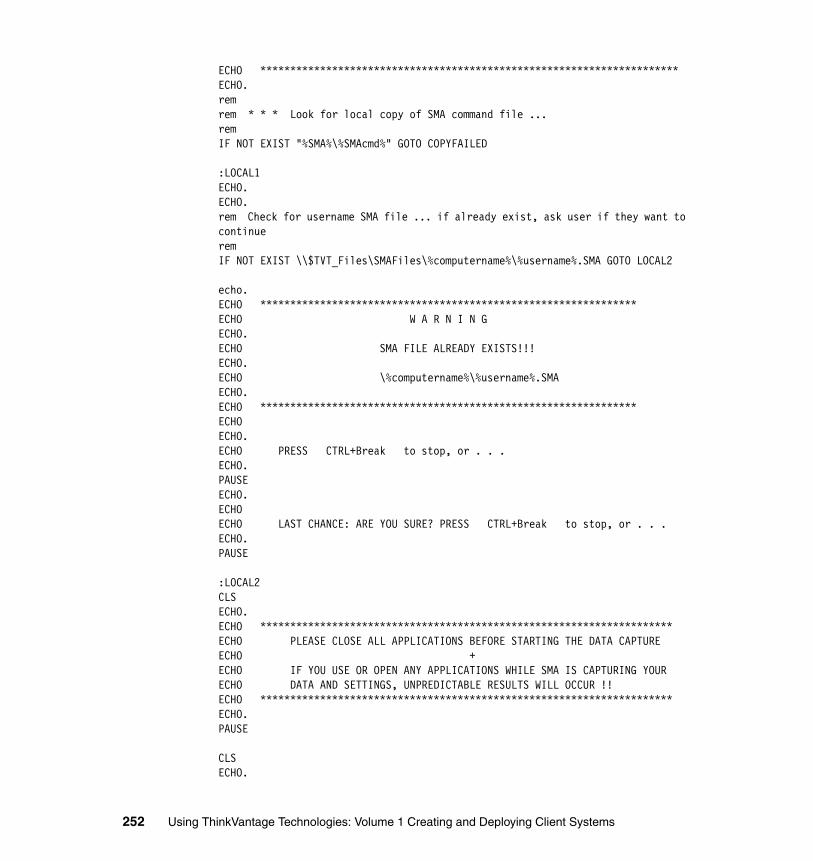
ECHO **********************************************************************ECHO.remrem * * * Look for local copy of SMA command file ...remIF NOT EXIST "%SMA%\%SMAcmd%" GOTO COPYFAILED
:LOCAL1ECHO.ECHO.rem Check for username SMA file ... if already exist, ask user if they want to continuerem IF NOT EXIST \\$TVT_Files\SMAFiles\%computername%\%username%.SMA GOTO LOCAL2
echo.ECHO ***************************************************************ECHO W A R N I N GECHO.ECHO SMA FILE ALREADY EXISTS!!!ECHO.ECHO \%computername%\%username%.SMAECHO.ECHO ***************************************************************ECHO ECHO.ECHO PRESS CTRL+Break to stop, or . . .ECHO.PAUSEECHO.ECHO ECHO LAST CHANCE: ARE YOU SURE? PRESS CTRL+Break to stop, or . . .ECHO.PAUSE
:LOCAL2CLSECHO.ECHO *********************************************************************ECHO PLEASE CLOSE ALL APPLICATIONS BEFORE STARTING THE DATA CAPTUREECHO +ECHO IF YOU USE OR OPEN ANY APPLICATIONS WHILE SMA IS CAPTURING YOURECHO DATA AND SETTINGS, UNPREDICTABLE RESULTS WILL OCCUR !!ECHO *********************************************************************ECHO.PAUSE
CLSECHO.
252 Using ThinkVantage Technologies: Volume 1 Creating and Deploying Client Systems
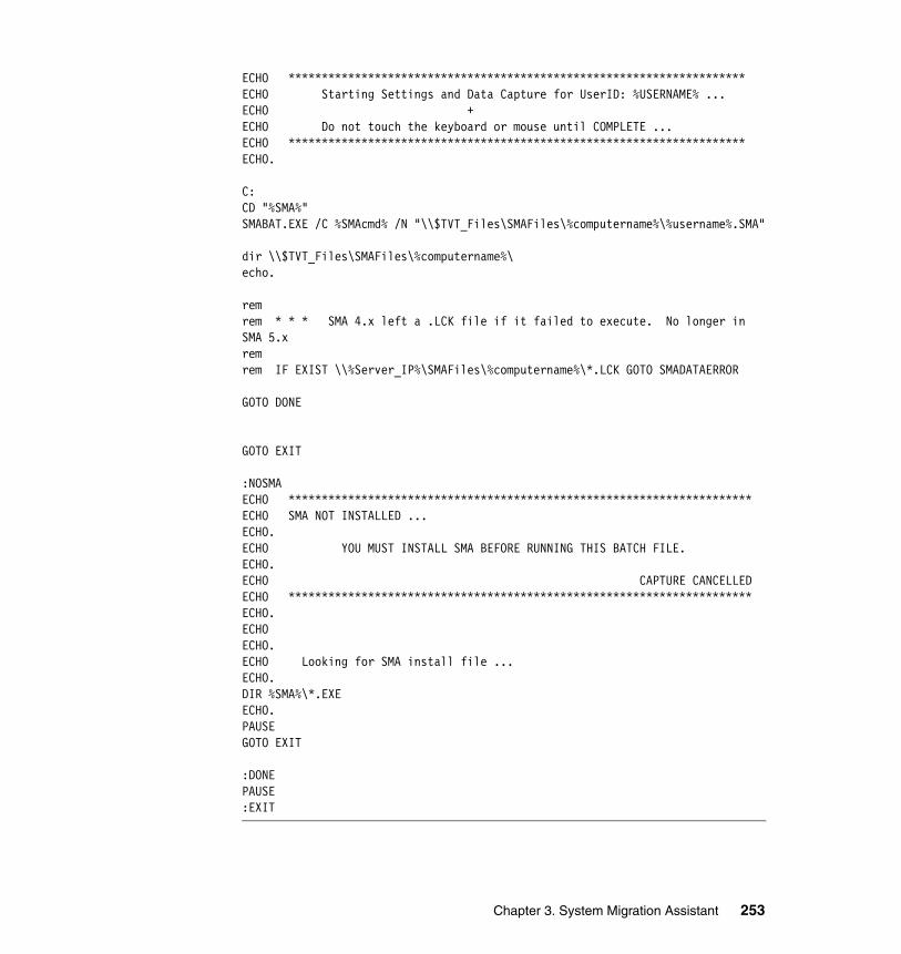
ECHO *********************************************************************ECHO Starting Settings and Data Capture for UserID: %USERNAME% ...ECHO + ECHO Do not touch the keyboard or mouse until COMPLETE ...ECHO *********************************************************************ECHO.
C:CD "%SMA%"SMABAT.EXE /C %SMAcmd% /N "\\$TVT_Files\SMAFiles\%computername%\%username%.SMA"
dir \\$TVT_Files\SMAFiles\%computername%\echo.
remrem * * * SMA 4.x left a .LCK file if it failed to execute. No longer in SMA 5.xremrem IF EXIST \\%Server_IP%\SMAFiles\%computername%\*.LCK GOTO SMADATAERROR
GOTO DONE
GOTO EXIT
:NOSMAECHO **********************************************************************ECHO SMA NOT INSTALLED ... ECHO.ECHO YOU MUST INSTALL SMA BEFORE RUNNING THIS BATCH FILE.ECHO.ECHO CAPTURE CANCELLEDECHO **********************************************************************ECHO.ECHO ECHO.ECHO Looking for SMA install file ...ECHO.DIR %SMA%\*.EXEECHO.PAUSEGOTO EXIT
:DONEPAUSE:EXIT
Chapter 3. System Migration Assistant 253
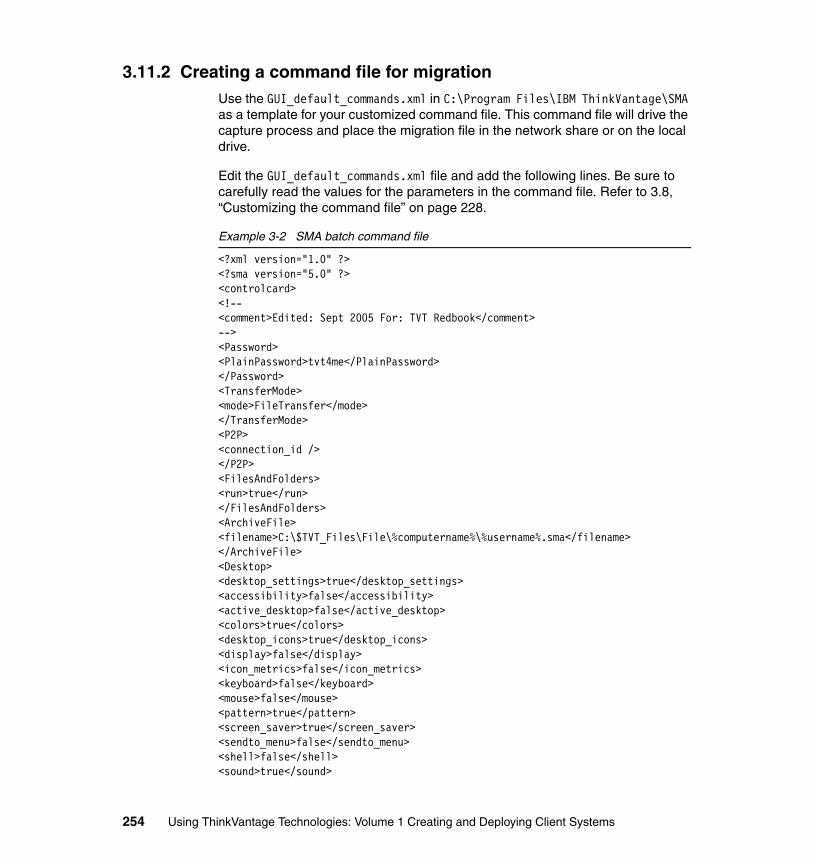
3.11.2 Creating a command file for migrationUse the GUI_default_commands.xml in C:\Program Files\IBM ThinkVantage\SMA as a template for your customized command file. This command file will drive the capture process and place the migration file in the network share or on the local drive.
Edit the GUI_default_commands.xml file and add the following lines. Be sure to carefully read the values for the parameters in the command file. Refer to 3.8, “Customizing the command file” on page 228.
Example 3-2 SMA batch command file
<?xml version="1.0" ?> <?sma version="5.0" ?> <controlcard> <!-- <comment>Edited: Sept 2005 For: TVT Redbook</comment>--> <Password> <PlainPassword>tvt4me</PlainPassword> </Password> <TransferMode> <mode>FileTransfer</mode> </TransferMode> <P2P> <connection_id /> </P2P> <FilesAndFolders> <run>true</run> </FilesAndFolders> <ArchiveFile> <filename>C:\$TVT_Files\File\%computername%\%username%.sma</filename> </ArchiveFile> <Desktop> <desktop_settings>true</desktop_settings> <accessibility>false</accessibility> <active_desktop>false</active_desktop> <colors>true</colors> <desktop_icons>true</desktop_icons> <display>false</display> <icon_metrics>false</icon_metrics> <keyboard>false</keyboard> <mouse>false</mouse> <pattern>true</pattern> <screen_saver>true</screen_saver> <sendto_menu>false</sendto_menu> <shell>false</shell> <sound>true</sound>
254 Using ThinkVantage Technologies: Volume 1 Creating and Deploying Client Systems
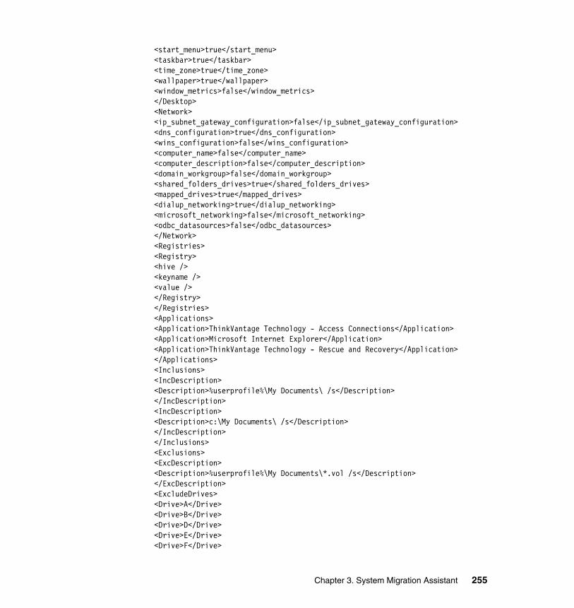
<start_menu>true</start_menu> <taskbar>true</taskbar> <time_zone>true</time_zone> <wallpaper>true</wallpaper> <window_metrics>false</window_metrics> </Desktop> <Network> <ip_subnet_gateway_configuration>false</ip_subnet_gateway_configuration> <dns_configuration>true</dns_configuration> <wins_configuration>false</wins_configuration> <computer_name>false</computer_name> <computer_description>false</computer_description> <domain_workgroup>false</domain_workgroup> <shared_folders_drives>true</shared_folders_drives> <mapped_drives>true</mapped_drives> <dialup_networking>true</dialup_networking> <microsoft_networking>false</microsoft_networking> <odbc_datasources>false</odbc_datasources> </Network> <Registries> <Registry> <hive /> <keyname /> <value /> </Registry> </Registries> <Applications> <Application>ThinkVantage Technology - Access Connections</Application> <Application>Microsoft Internet Explorer</Application> <Application>ThinkVantage Technology - Rescue and Recovery</Application> </Applications> <Inclusions> <IncDescription> <Description>%userprofile%\My Documents\ /s</Description> </IncDescription> <IncDescription> <Description>c:\My Documents\ /s</Description> </IncDescription> </Inclusions> <Exclusions> <ExcDescription> <Description>%userprofile%\My Documents\*.vol /s</Description> </ExcDescription> <ExcludeDrives> <Drive>A</Drive> <Drive>B</Drive> <Drive>D</Drive> <Drive>E</Drive> <Drive>F</Drive>
Chapter 3. System Migration Assistant 255
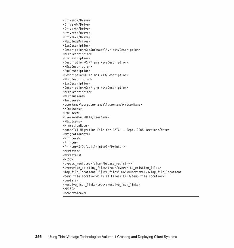
<Drive>S</Drive> <Drive>W</Drive> <Drive>X</Drive> <Drive>Y</Drive> <Drive>Z</Drive> </ExcludeDrives> <ExcDescription> <Description>C:\Software\*.* /s</Description> </ExcDescription> <ExcDescription> <Description>C:\*.sma /s</Description> </ExcDescription> <ExcDescription> <Description>C:\*.mp3 /s</Description> </ExcDescription> <ExcDescription> <Description>C:\*.gho /s</Description> </ExcDescription> </Exclusions> <IncUsers> <UserName>%computername%\%username%</UserName> </IncUsers> <ExcUsers> <UserName>ASPNET</UserName> </ExcUsers> <MigrationNote> <Note>TVT Migration File for BATCH - Sept. 2005 Version</Note> </MigrationNote> <Printers> <Printer> <Printer>$(DefaultPrinter)</Printer> </Printer> </Printers> <MISC> <bypass_registry>false</bypass_registry> <overwrite_existing_files>true</overwrite_existing_files> <log_file_location>C:\$TVT_files\LOGS\%username%\</log_file_location> <temp_file_location>C:\$TVT_Files\TEMP</temp_file_location> <quota /> <resolve_icon_links>true</resolve_icon_links> </MISC> </controlcard>
256 Using ThinkVantage Technologies: Volume 1 Creating and Deploying Client Systems
3.12 ThinkVantage integration considerationsThis section discusses ways in which System Migration Assistant can integrate with other tools. System Migration Assistant is capable of migrating PC settings and data, making it ideal for deployment by other ThinkVantage Technologies.
� 3.12.1, “Integration with ImageUltra Builder” on page 257
� 3.12.2, “Integration with LANDesk” on page 257
3.12.1 Integration with ImageUltra BuilderFor details about how to deploy System Migration Assistant as a module during an image load, refer to 2.11, “Deploy and install with ImageUltra Builder” on page 144. This allows for immediate restoration of user settings that may have been captures before a PC cascade or new system rollout.
3.12.2 Integration with LANDeskA new version of LANDesk has been released recently called LANDesk Management Suite 8.6 for ThinkVantage Technologies. In addition to providing the standard LANDesk Management Suite, it includes integration with many of the ThinkVantage Technologies.
LANDesk Management Suite 8.6 for ThinkVantage Technologies is a co-branded, co-developed, comprehensive suite of desktop management tools tightly integrated into a centrally-located management console. The suite is divided into several high-level components or modules, each representing a different grouping of functionality. System Migration Assistant is one of the ThinkVantage Technologies that is integrated into LANDesk.
This version of LANDesk includes System Migration Assistant to provide an ideal solution for a large corporation moving hundreds of users’ data over an enterprise network with a centrally managed console.
� You can use the LANDesk Management Suite Console to launch SMA scripts and command files. See Figure 3-36.
Chapter 3. System Migration Assistant 257
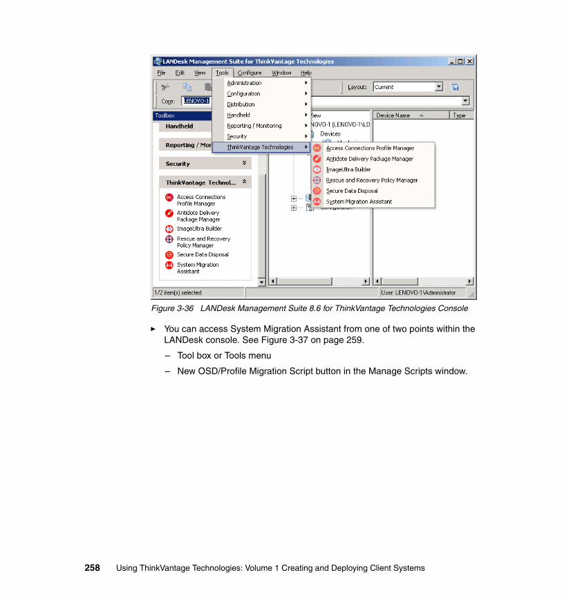
Figure 3-36 LANDesk Management Suite 8.6 for ThinkVantage Technologies Console
� You can access System Migration Assistant from one of two points within the LANDesk console. See Figure 3-37 on page 259.
– Tool box or Tools menu
– New OSD/Profile Migration Script button in the Manage Scripts window.
258 Using ThinkVantage Technologies: Volume 1 Creating and Deploying Client Systems
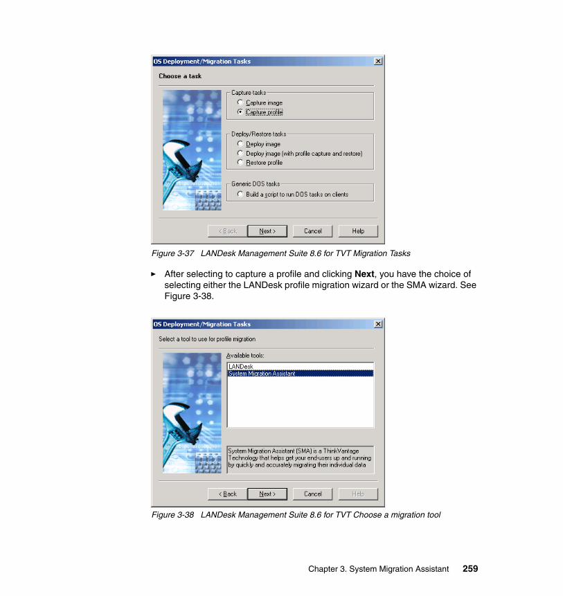
Figure 3-37 LANDesk Management Suite 8.6 for TVT Migration Tasks
� After selecting to capture a profile and clicking Next, you have the choice of selecting either the LANDesk profile migration wizard or the SMA wizard. See Figure 3-38.
Figure 3-38 LANDesk Management Suite 8.6 for TVT Choose a migration tool
Chapter 3. System Migration Assistant 259
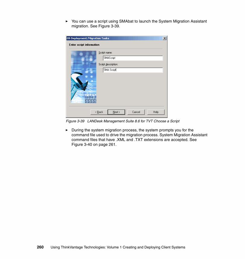
� You can use a script using SMAbat to launch the System Migration Assistant migration. See Figure 3-39.
Figure 3-39 LANDesk Management Suite 8.6 for TVT Choose a Script
� During the system migration process, the system prompts you for the command file used to drive the migration process. System Migration Assistant command files that have .XML and .TXT extensions are accepted. See Figure 3-40 on page 261.
260 Using ThinkVantage Technologies: Volume 1 Creating and Deploying Client Systems
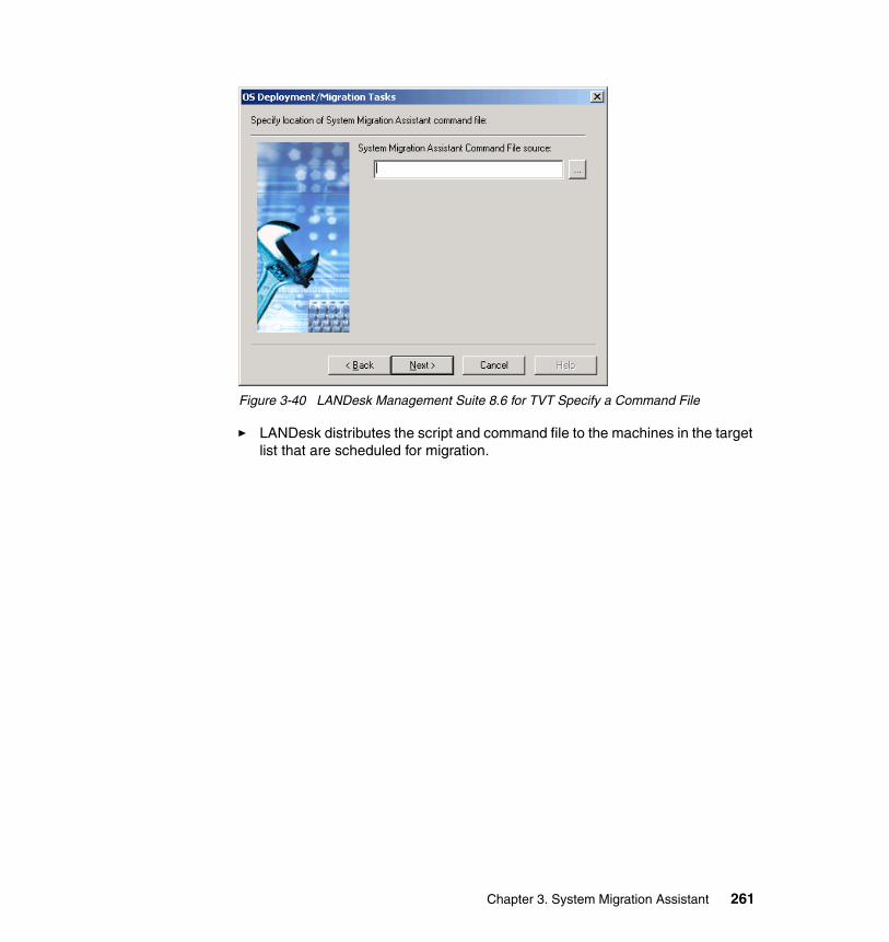
Figure 3-40 LANDesk Management Suite 8.6 for TVT Specify a Command File
� LANDesk distributes the script and command file to the machines in the target list that are scheduled for migration.
Chapter 3. System Migration Assistant 261

262 Using ThinkVantage Technologies: Volume 1 Creating and Deploying Client Systems
Chapter 4. Secure Data Disposal
During the retirement phase of the PC life cycle, many companies dispose of their PCs without proper removal of confidential data. This causes a serious concern because unauthorized people can retrieve information on the hard disks. What does this mean? Many companies think that formatting a hard disk removes and destroys the data on hard disks. They are unaware that others can still retrieve confidential data from these systems.
In most operating systems (Windows XP, Windows 2000, Windows 95, Windows NT, Windows 98, Linux®, and so on), deleted files are not necessarily erased. In many cases, the only thing erased is the logical link to the file. The IBM tool for Secure Data Disposal is known as SCRUB3. SCRUB3 is indifferent with respect to the operating system on a hard disk. SCRUB3 ensures it permanently removes any critical data from a PC before you discard the PC.
Whether you are cascading a PC in your organization or retiring the PC, your IT organization, using SCRUB3, benefits from the following:
� Data, programs, and possible viruses are destroyed on a PC before you load a new image.
� Sensitive and/or confidential information is destroyed permanently.
This chapter provides information regarding the use of this tool and how you can implement several practical applications of SCRUB3.
4
© Copyright IBM Corp. 2005. All rights reserved. 263
4.1 Secure Data Disposal: OverviewSecure Data Disposal is a Windows program used to create a DOS bootable floppy needed to run the SCRUB3 utility that wipes sensitive data from hard drives. Secure Data Disposal allows the technical staff to define the level of disposal, add custom information to the client report file, and override the pattern with a customer-defined pattern.
IBM’s SCRUB3 utility permanently erases information on a hard disk so it is not be retrievable by anyone else. The utility allows for different levels of security depending on the nature of the data that is on the hard disk.
Various organizations use this tool in either the retirement phase or when they need to cascade machines within an organization to ensure confidential information is kept secure.
This is a DOS-based utility that can be executed through the RDM console or from a DOS command prompt.
4.1.1 System Requirements
System requirements for Secure Data Disposal program� Intel x86-compatible processor � 32 MB RAM � Microsoft Windows 2000, Windows XP, or Windows 2003 Server � 15 MB of available hard drive space � Third Party CD Burning Software (to burn optional bootable ISO image to
CD-ROM)
System requirements for SDD DOS tools� Intel x86-compatible processor (must be able to run PC-DOS 7.1)� 8 MB RAM � 1.44 MB floppy drive or (optional) bootable CD-ROM BIOS support� 16-color VGA video� Hard drive controllers of type: IDE, EIDE, SCSI, or SATA � Hard drives with Int13 or Interrupt 13 extensions BIOS support� Windows 2000, Windows XP, or Windows 2003 Server installation (to create
DOS bootable diskette)
4.1.2 Considerations� Secure Data Disposal does not support USB hard drives.
264 Using ThinkVantage Technologies: Volume 1 Creating and Deploying Client Systems
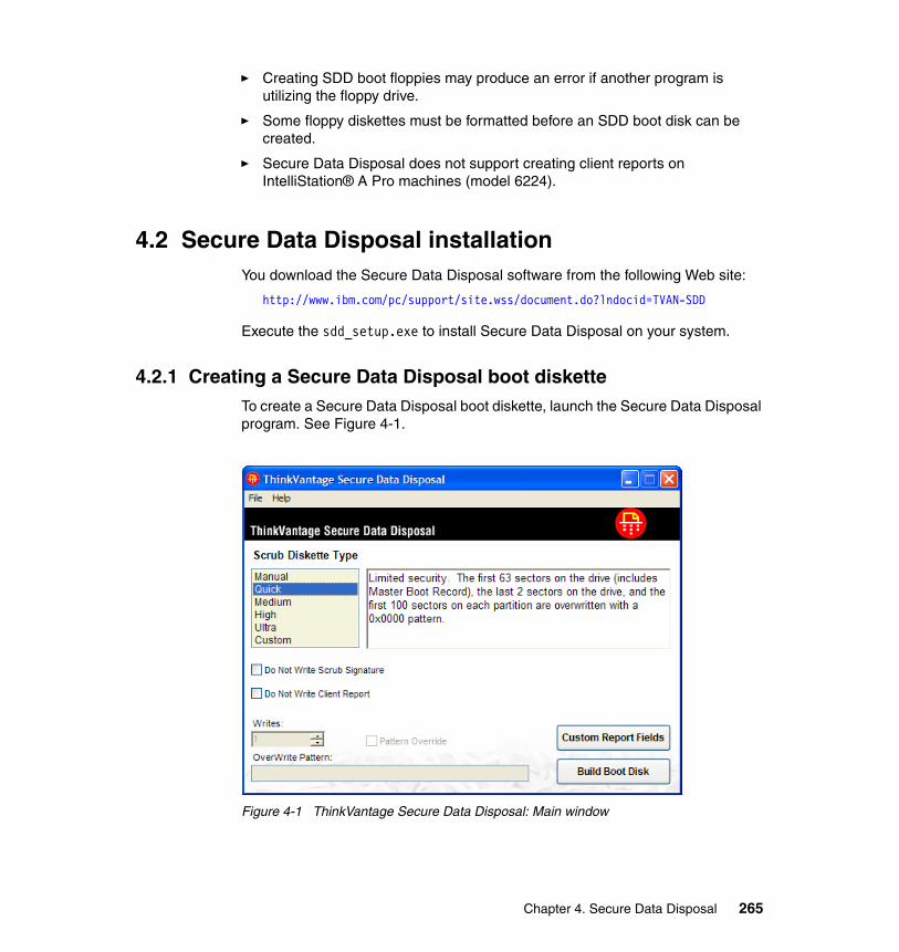
� Creating SDD boot floppies may produce an error if another program is utilizing the floppy drive.
� Some floppy diskettes must be formatted before an SDD boot disk can be created.
� Secure Data Disposal does not support creating client reports on IntelliStation® A Pro machines (model 6224).
4.2 Secure Data Disposal installationYou download the Secure Data Disposal software from the following Web site:
http://www.ibm.com/pc/support/site.wss/document.do?lndocid=TVAN-SDD
Execute the sdd_setup.exe to install Secure Data Disposal on your system.
4.2.1 Creating a Secure Data Disposal boot disketteTo create a Secure Data Disposal boot diskette, launch the Secure Data Disposal program. See Figure 4-1.
Figure 4-1 ThinkVantage Secure Data Disposal: Main window
Chapter 4. Secure Data Disposal 265
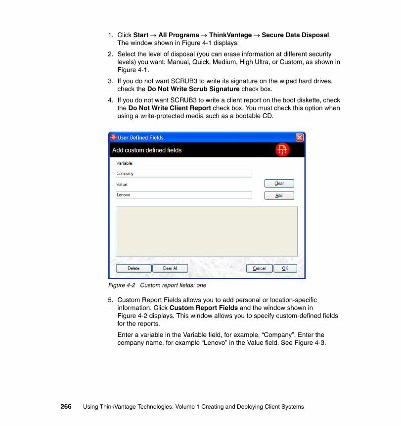
1. Click Start → All Programs → ThinkVantage → Secure Data Disposal. The window shown in Figure 4-1 displays.
2. Select the level of disposal (you can erase information at different security levels) you want: Manual, Quick, Medium, High Ultra, or Custom, as shown in Figure 4-1.
3. If you do not want SCRUB3 to write its signature on the wiped hard drives, check the Do Not Write Scrub Signature check box.
4. If you do not want SCRUB3 to write a client report on the boot diskette, check the Do Not Write Client Report check box. You must check this option when using a write-protected media such as a bootable CD.
Figure 4-2 Custom report fields: one
5. Custom Report Fields allows you to add personal or location-specific information. Click Custom Report Fields and the window shown in Figure 4-2 displays. This window allows you to specify custom-defined fields for the reports.
Enter a variable in the Variable field, for example, “Company”. Enter the company name, for example “Lenovo” in the Value field. See Figure 4-3.
266 Using ThinkVantage Technologies: Volume 1 Creating and Deploying Client Systems
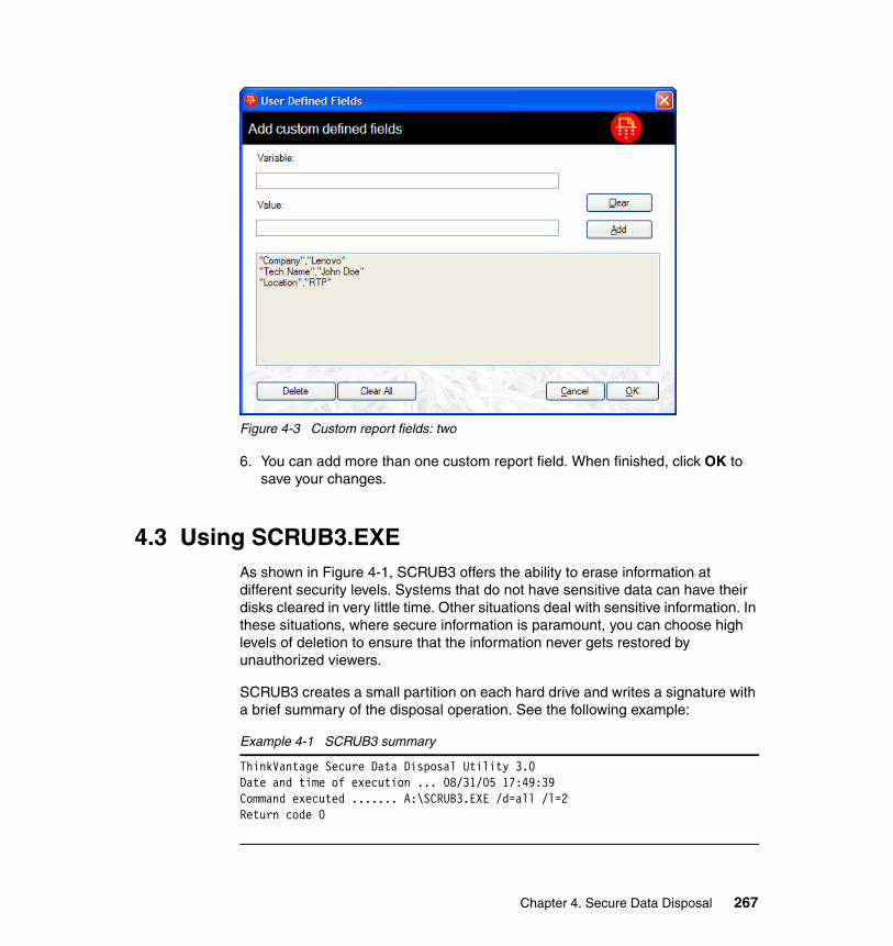
Figure 4-3 Custom report fields: two
6. You can add more than one custom report field. When finished, click OK to save your changes.
4.3 Using SCRUB3.EXEAs shown in Figure 4-1, SCRUB3 offers the ability to erase information at different security levels. Systems that do not have sensitive data can have their disks cleared in very little time. Other situations deal with sensitive information. In these situations, where secure information is paramount, you can choose high levels of deletion to ensure that the information never gets restored by unauthorized viewers.
SCRUB3 creates a small partition on each hard drive and writes a signature with a brief summary of the disposal operation. See the following example:
Example 4-1 SCRUB3 summary
ThinkVantage Secure Data Disposal Utility 3.0Date and time of execution ... 08/31/05 17:49:39Command executed ....... A:\SCRUB3.EXE /d=all /l=2Return code 0
Chapter 4. Secure Data Disposal 267
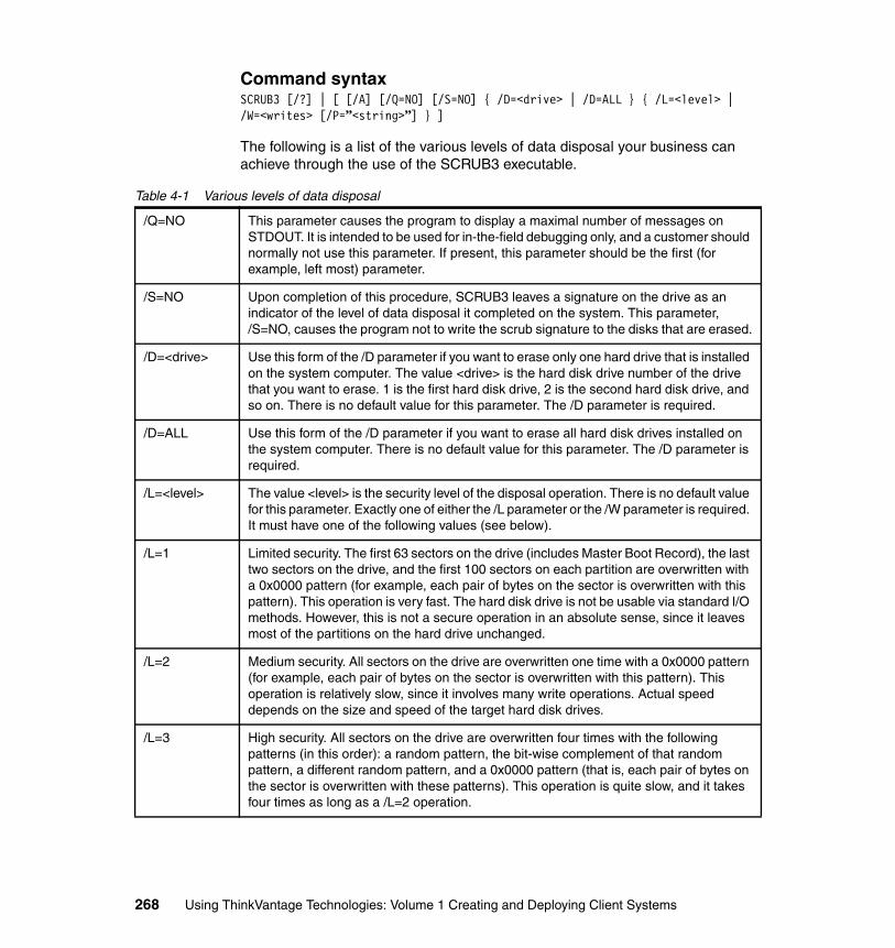
Command syntaxSCRUB3 [/?] | [ [/A] [/Q=NO] [/S=NO] { /D=<drive> | /D=ALL } { /L=<level> | /W=<writes> [/P=”<string>”] } ]
The following is a list of the various levels of data disposal your business can achieve through the use of the SCRUB3 executable.
Table 4-1 Various levels of data disposal
/Q=NO This parameter causes the program to display a maximal number of messages on STDOUT. It is intended to be used for in-the-field debugging only, and a customer should normally not use this parameter. If present, this parameter should be the first (for example, left most) parameter.
/S=NO Upon completion of this procedure, SCRUB3 leaves a signature on the drive as an indicator of the level of data disposal it completed on the system. This parameter, /S=NO, causes the program not to write the scrub signature to the disks that are erased.
/D=<drive> Use this form of the /D parameter if you want to erase only one hard drive that is installed on the system computer. The value <drive> is the hard disk drive number of the drive that you want to erase. 1 is the first hard disk drive, 2 is the second hard disk drive, and so on. There is no default value for this parameter. The /D parameter is required.
/D=ALL Use this form of the /D parameter if you want to erase all hard disk drives installed on the system computer. There is no default value for this parameter. The /D parameter is required.
/L=<level> The value <level> is the security level of the disposal operation. There is no default value for this parameter. Exactly one of either the /L parameter or the /W parameter is required. It must have one of the following values (see below).
/L=1 Limited security. The first 63 sectors on the drive (includes Master Boot Record), the last two sectors on the drive, and the first 100 sectors on each partition are overwritten with a 0x0000 pattern (for example, each pair of bytes on the sector is overwritten with this pattern). This operation is very fast. The hard disk drive is not be usable via standard I/O methods. However, this is not a secure operation in an absolute sense, since it leaves most of the partitions on the hard drive unchanged.
/L=2 Medium security. All sectors on the drive are overwritten one time with a 0x0000 pattern (for example, each pair of bytes on the sector is overwritten with this pattern). This operation is relatively slow, since it involves many write operations. Actual speed depends on the size and speed of the target hard disk drives.
/L=3 High security. All sectors on the drive are overwritten four times with the following patterns (in this order): a random pattern, the bit-wise complement of that random pattern, a different random pattern, and a 0x0000 pattern (that is, each pair of bytes on the sector is overwritten with these patterns). This operation is quite slow, and it takes four times as long as a /L=2 operation.
268 Using ThinkVantage Technologies: Volume 1 Creating and Deploying Client Systems
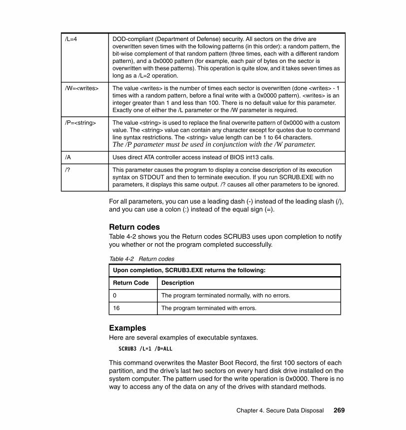
For all parameters, you can use a leading dash (-) instead of the leading slash (/), and you can use a colon (:) instead of the equal sign (=).
Return codesTable 4-2 shows you the Return codes SCRUB3 uses upon completion to notify you whether or not the program completed successfully.
Table 4-2 Return codes
ExamplesHere are several examples of executable syntaxes.
SCRUB3 /L=1 /D=ALL
This command overwrites the Master Boot Record, the first 100 sectors of each partition, and the drive’s last two sectors on every hard disk drive installed on the system computer. The pattern used for the write operation is 0x0000. There is no way to access any of the data on any of the drives with standard methods.
/L=4 DOD-compliant (Department of Defense) security. All sectors on the drive are overwritten seven times with the following patterns (in this order): a random pattern, the bit-wise complement of that random pattern (three times, each with a different random pattern), and a 0x0000 pattern (for example, each pair of bytes on the sector is overwritten with these patterns). This operation is quite slow, and it takes seven times as long as a /L=2 operation.
/W=<writes> The value <writes> is the number of times each sector is overwritten (done <writes> - 1 times with a random pattern, before a final write with a 0x0000 pattern). <writes> is an integer greater than 1 and less than 100. There is no default value for this parameter. Exactly one of either the /L parameter or the /W parameter is required.
/P=<string> The value <string> is used to replace the final overwrite pattern of 0x0000 with a custom value. The <string> value can contain any character except for quotes due to command line syntax restrictions. The <string> value length can be 1 to 64 characters.The /P parameter must be used in conjunction with the /W parameter.
/A Uses direct ATA controller access instead of BIOS int13 calls.
/? This parameter causes the program to display a concise description of its execution syntax on STDOUT and then to terminate execution. If you run SCRUB.EXE with no parameters, it displays this same output. /? causes all other parameters to be ignored.
Upon completion, SCRUB3.EXE returns the following:
Return Code Description
0 The program terminated normally, with no errors.
16 The program terminated with errors.
Chapter 4. Secure Data Disposal 269
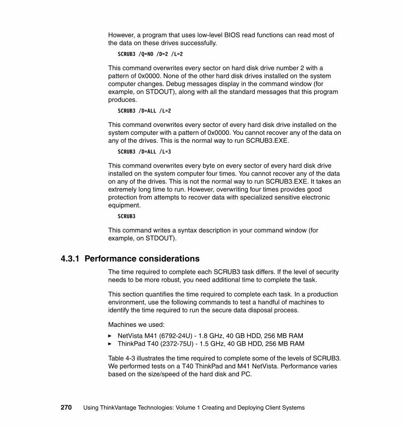
However, a program that uses low-level BIOS read functions can read most of the data on these drives successfully.
SCRUB3 /Q=NO /D=2 /L=2
This command overwrites every sector on hard disk drive number 2 with a pattern of 0x0000. None of the other hard disk drives installed on the system computer changes. Debug messages display in the command window (for example, on STDOUT), along with all the standard messages that this program produces.
SCRUB3 /D=ALL /L=2
This command overwrites every sector of every hard disk drive installed on the system computer with a pattern of 0x0000. You cannot recover any of the data on any of the drives. This is the normal way to run SCRUB3.EXE.
SCRUB3 /D=ALL /L=3
This command overwrites every byte on every sector of every hard disk drive installed on the system computer four times. You cannot recover any of the data on any of the drives. This is not the normal way to run SCRUB3.EXE. It takes an extremely long time to run. However, overwriting four times provides good protection from attempts to recover data with specialized sensitive electronic equipment.
SCRUB3
This command writes a syntax description in your command window (for example, on STDOUT).
4.3.1 Performance considerationsThe time required to complete each SCRUB3 task differs. If the level of security needs to be more robust, you need additional time to complete the task.
This section quantifies the time required to complete each task. In a production environment, use the following commands to test a handful of machines to identify the time required to run the secure data disposal process.
Machines we used:
� NetVista M41 (6792-24U) - 1.8 GHz, 40 GB HDD, 256 MB RAM� ThinkPad T40 (2372-75U) - 1.5 GHz, 40 GB HDD, 256 MB RAM
Table 4-3 illustrates the time required to complete some of the levels of SCRUB3. We performed tests on a T40 ThinkPad and M41 NetVista. Performance varies based on the size/speed of the hard disk and PC.
270 Using ThinkVantage Technologies: Volume 1 Creating and Deploying Client Systems
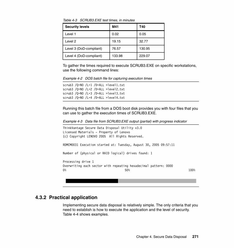
Table 4-3 SCRUB3.EXE test times, in minutes
To gather the times required to execute SCRUB3.EXE on specific workstations, use the following command lines:
Example 4-2 DOS batch file for capturing execution times
scrub3 /Q=NO /L=1 /D=ALL >level1.txtscrub3 /Q=NO /L=2 /D=ALL >level2.txtscrub3 /Q=NO /L=3 /D=ALL >level3.txtscrub3 /Q=NO /L=4 /D=ALL >level4.txt
Running this batch file from a DOS boot disk provides you with four files that you can use to gather the execution times of SCRUB3.EXE.
Example 4-3 Data file from SCRUB3.EXE output (partial) with progress indicator
ThinkVantage Secure Data Disposal Utility v3.0Licensed Materials - Property of Lenovo(c) Copyright LENOVO 2005 All Rights Reserved.
RDMCM0031 Execution started at: Tuesday, August 30, 2005 09:57:11
Number of (physical or RAID logical) drives found: 1
Processing drive 1Overwriting each sector with repeating hexadecimal pattern: 00000% 50% 100%
4.3.2 Practical applicationImplementing secure data disposal is relatively simple. The only criteria that you need to establish is how to execute the application and the level of security. Table 4-4 shows examples.
Security levels M41 T40
Level 1 0.02 0.05
Level 2 19.15 32.77
Level 3 (DoD-compliant) 76.57 130.95
Level 4 (DoD-compliant) 133.98 229.07
Chapter 4. Secure Data Disposal 271
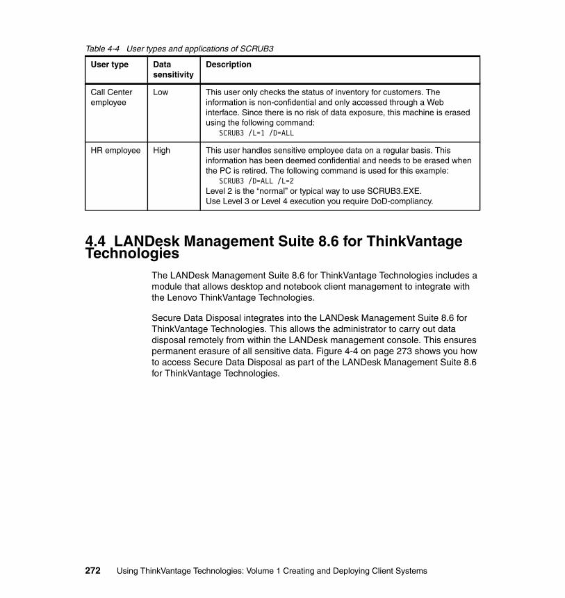
Table 4-4 User types and applications of SCRUB3
4.4 LANDesk Management Suite 8.6 for ThinkVantage Technologies
The LANDesk Management Suite 8.6 for ThinkVantage Technologies includes a module that allows desktop and notebook client management to integrate with the Lenovo ThinkVantage Technologies.
Secure Data Disposal integrates into the LANDesk Management Suite 8.6 for ThinkVantage Technologies. This allows the administrator to carry out data disposal remotely from within the LANDesk management console. This ensures permanent erasure of all sensitive data. Figure 4-4 on page 273 shows you how to access Secure Data Disposal as part of the LANDesk Management Suite 8.6 for ThinkVantage Technologies.
User type Data sensitivity
Description
Call Center employee
Low This user only checks the status of inventory for customers. The information is non-confidential and only accessed through a Web interface. Since there is no risk of data exposure, this machine is erased using the following command:
SCRUB3 /L=1 /D=ALL
HR employee High This user handles sensitive employee data on a regular basis. This information has been deemed confidential and needs to be erased when the PC is retired. The following command is used for this example:
SCRUB3 /D=ALL /L=2Level 2 is the “normal” or typical way to use SCRUB3.EXE.Use Level 3 or Level 4 execution you require DoD-compliancy.
272 Using ThinkVantage Technologies: Volume 1 Creating and Deploying Client Systems
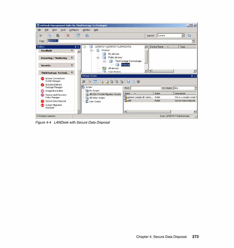
Figure 4-4 LANDesk with Secure Data Disposal
Chapter 4. Secure Data Disposal 273

274 Using ThinkVantage Technologies: Volume 1 Creating and Deploying Client Systems

Chapter 5. ThinkVantage Access Connections
This chapter describes the installation and implementation of the ThinkVantage Access Connections tool.
In this chapter, we discuss the following topics:
� 5.1, “Access Connections overview” on page 276
� 5.2, “Prerequisites” on page 277
� 5.4, “Creating ThinkVantage Access Connections profiles” on page 282
� 5.5, “Customization and advanced features” on page 305
� 5.6, “Enabler for Administrator Profile Deployment Feature” on page 329
5
© Copyright IBM Corp. 2005. All rights reserved. 275
5.1 Access Connections overview ThinkVantage Access Connections is a connectivity assistance program for your Lenovo and IBM ThinkPad computer that allows you to create and manage location profiles. Each location profile stores all of the network and Internet configuration settings that are necessary to connect to a network infrastructure from a specific location, such as home or work. By switching between location profiles as you move your computer from place to place, you can connect quickly and easily to a network without manually having to reconfigure your settings and restarting your computer each time. The location profile also allows users to specify different default printers, default home pages for Internet Explorer, and security settings for specific locations. The location profile also allows users to start different applications automatically in different locations.
You make the network connection using a modem, a wired network adapter (Ethernet or Token Ring), a broadband device (Digital Subscriber Line (DSL), cable modem, or Integrated Services Digital Network (ISDN), satellite connection devices, wireless local area network (Wireless LAN), or wireless wide area network (Wireless WAN). ThinkVantage Access Connections also supports Virtual Private Networking (VPN) connections.
By switching between location profiles as users move their computers from place to place, they quickly and easily connect to a network without manually reconfiguring settings or restarting the computer each time. ThinkVantage Access Connections also allows the user to view and connect to Bluetooth devices and to set Bluetooth security options. It enables switching network settings quickly and switching Internet settings by selecting a location profile.
Summary of changes for Version 3.81� Support for the following Wireless Lan and Wireless WAN Adapter:
– 11a/b/g Wireless LAN Mini PCI Express Adapter– Verizon Wireless WAN modem
Summary of changes for Version 3.7x� Support EAP-FAST for the following Wireless LAN adapters:
– IBM Dual-Band Wi-Fi Wireless Mini PCI Adapter– IBM 11a/b/g Wireless LAN Mini PCI Adapter– IBM 11b/g Wireless LAN Mini PCI Adapter– IBM 11a/b/g Wireless LAN Mini PCI Adapter II– Intel PRO/Wireless 2200BG Network Connection– Intel PRO/Wireless 2915ABG Network Connection– Cisco Systems Mini PCI Wireless LAN Adapter
276 Using ThinkVantage Technologies: Volume 1 Creating and Deploying Client Systems
� Support WPA-2 for the following Wireless Lan adapters:
– IBM Dual-Band Wi-Fi Wireless Mini PCI Adapter– IBM 11a/b/g Wireless LAN Mini PCI Adapter– IBM 11b/g Wireless LAN Mini PCI Adapter– IBM 11a/b/g Wireless LAN Mini PCI Adapter II– Intel PRO/Wireless 2200BG Network Connection– Intel PRO/Wireless 2915ABG Network Connection
Summary of changes for Version 3.5x� Support for ThinkPad T43 and T43p� Support for Traditional Chinese, Simplified Chinese, and Korean� Support for CCKM in LEAP connection� Support for Network Profile Deployment to disable IE settings, Security
settings, printer settings, and program settings
5.2 PrerequisitesBefore installing Access Connections, you must consider where to install it and what network profiles you want to create. Consider the following list of system considerations and limitations before installing Access Connections.
� Operating systems supported:
– Microsoft Windows 2000– Microsoft Windows XP
� Language-independent: can be used with any language system
� Supported on the following ThinkPad systems:
– A20m, A20p, A21e, A21m, A21p, A22e, A22m, A22p, A30, A30p, A31, A31p
– G40, G41– R30, R31, R32, R40, R40e, R50, R50e, R50p, R51, R51e, R52– S31– T20, T21, T22, T23, T30, T40, T40p, T41, T41p, T42, T42p, T43, T43p– X20, X21, X22, X23, X24, X30, X31, X32, X40, X41, X41 Tablet– Z60t, Z60m– Transnote
Note: This program is language-independent. You can use it with any language system. Only IBM systems support ThinkVantage Access Connections Version 3. Future releases will provide limited compatibility with non-IBM hardware via a generic NDIS interface.
Chapter 5. ThinkVantage Access Connections 277
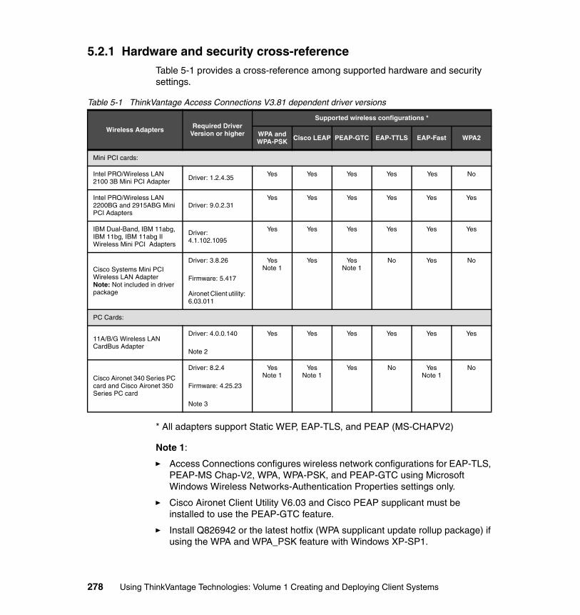
5.2.1 Hardware and security cross-referenceTable 5-1 provides a cross-reference among supported hardware and security settings.
Table 5-1 ThinkVantage Access Connections V3.81 dependent driver versions
* All adapters support Static WEP, EAP-TLS, and PEAP (MS-CHAPV2)
Note 1:
� Access Connections configures wireless network configurations for EAP-TLS, PEAP-MS Chap-V2, WPA, WPA-PSK, and PEAP-GTC using Microsoft Windows Wireless Networks-Authentication Properties settings only.
� Cisco Aironet Client Utility V6.03 and Cisco PEAP supplicant must be installed to use the PEAP-GTC feature.
� Install Q826942 or the latest hotfix (WPA supplicant update rollup package) if using the WPA and WPA_PSK feature with Windows XP-SP1.
Wireless Adapters Required Driver Version or higher
Supported wireless configurations *
WPA and WPA-PSK Cisco LEAP PEAP-GTC EAP-TTLS EAP-Fast WPA2
Mini PCI cards:
Intel PRO/Wireless LAN 2100 3B Mini PCI Adapter Driver: 1.2.4.35 Yes Yes Yes Yes Yes No
Intel PRO/Wireless LAN 2200BG and 2915ABG Mini PCI Adapters
Driver: 9.0.2.31Yes Yes Yes Yes Yes Yes
IBM Dual-Band, IBM 11abg, IBM 11bg, IBM 11abg II Wireless Mini PCI Adapters
Driver: 4.1.102.1095
Yes Yes Yes Yes Yes Yes
Cisco Systems Mini PCI Wireless LAN Adapter Note: Not included in driver package
Driver: 3.8.26
Firmware: 5.417
Aironet Client utility: 6.03.011
YesNote 1
Yes YesNote 1
No Yes No
PC Cards:
11A/B/G Wireless LAN CardBus Adapter
Driver: 4.0.0.140
Note 2
Yes Yes Yes Yes Yes Yes
Cisco Aironet 340 Series PC card and Cisco Aironet 350 Series PC card
Driver: 8.2.4
Firmware: 4.25.23
Note 3
YesNote 1
YesNote 1
Yes No YesNote 1
No
278 Using ThinkVantage Technologies: Volume 1 Creating and Deploying Client Systems
Note 2:
� The IBM 11a/b/g Wireless CardBus Adapter cannot be used on IBM ThinkPad systems that are also equipped with an internal Intel PRO/Wireless LAN 2100 3B Mini PCI Adapter.
Note 3:
� Lenovo recommends contacting Cisco Systems, Inc., to get the latest device driver:
http://www.cisco.com/pcgi-bin/tablebuild.pl/aironet-utils-win
5.3 InstallationThe following section details the extraction and installation of Access Connections. There are two types of installation. The first type is “Automated installation” on page 280 and the second type is the “Manual installation” on page 280. Companies that need to install ThinkVantage Access Connections on a large number of systems or that wish to insure that Access Connections is installed in a customized directory use the automated process. Both types of deployment allow for the use of predefined profiles made with ThinkVantage Access Connections’ administration tool.
5.3.1 Extraction of source filesBefore any installation can take place, you must download the ThinkVantage Access Connections setup files and extract them to a temporary file.
1. To begin the installation process, download the compressed self-extracting executable file from the following URL:
http://www.ibm.com/pc/support/site.wss/document.do?lndocid=MIGR-4ZLNJB
2. Run the self-extracting executable file to extract installation files.
3. Accept the terms of the license agreement; then click Next to proceed.
4. Select a temporary location to extract the installation files; then click Next.
Click Finish to complete the extraction of the installation files. Note where the files were extracted.
Note: If ThinkVantage Access Connections is already on the system, you must remove it before proceeding with the installation process detailed below. See Section 5.7, “Troubleshooting” on page 341, for details about removing ThinkVantage Access Connections.
Chapter 5. ThinkVantage Access Connections 279
Proceed with either “Automated installation” on page 280 or “Manual installation” on page 280.
5.3.2 Automated installationThe automated installation provides a means of installing ThinkVantage Access Connections without any user intervention.
Execute the following steps to complete the automated installation process:
1. Start Windows 2000/XP; log on with administrative privileges.
2. If you plan to use customized predefined profiles, copy the two files to the same directory where ThinkVantage Access Connections was extracted.
3. Extract the ThinkVantage Access Connections drivers to the hard disk drive.
4. Click Start, then click Run.
5. Type the following:
\\directory that Access Connections was extracted to\start /WAIT setup.exe -s -SMS -f2%temp%\setup.log
6. Click OK.
If you used an automated installation package to install ThinkVantage Access Connections, now skip to 5.4, “Creating ThinkVantage Access Connections profiles” on page 282.
5.3.3 Manual installationThe manual installation of ThinkVantage Access Connections is useful to users who want to control the installation directory or need to understand the installation settings to develop an automated process. After you extract the installation files, you can begin the installation.
1. Run the Setup.exe file from the location where the files have been extracted.
Note: For more information about automating the installation of this application, refer to the chapter on Software Delivery Center in Using ThinkVantage Technologies Volume 2: Maintaining and Recovering Client Systems, SG24-7107.
Tip: There is be no notification when the installation completes. The system does not restart automatically. You must restart the system before you can use ThinkVantage Access Connections for the first time.
280 Using ThinkVantage Technologies: Volume 1 Creating and Deploying Client Systems
2. When the welcome window opens, click Next to continue the installation.
3. Choose an installation location; then click Next to continue.
4. Select the program folder, then click Next.
5. Insure the installation information is correct; click Next to continue.
6. If prompted to restart, select Yes, I want to restart my computer now. Click Finish. You must restart the computer before you use the application.
5.3.4 Installation with wireless LAN driver packYou can download ThinkVantage Access Connections along with a set of wireless LAN drivers for most of the current integrated wireless LAN adapters available for the ThinkPad. This pack also includes the compatible On Screen Display utility that is required for using the Fn + F5 hotkey.
You download the ThinkVantage Access Connections with wireless LAN driver pack from the same location as the Access Connections installer.
To install, first you must extract the files from the ThinkVantage Access Connections with wireless LAN driver pack as explained in 5.3.1, “Extraction of source files” on page 279.
After extracting the installation files to a temporary folder, you can choose between manual and unattended installations.
Manual installation1. Start Windows 2000/XP and log on with administrative privileges.
2. Run the Setup.exe file from the location where the files have been extracted.
3. When the installer windows opens, make sure “Install or upgrade drivers OS software” option is checked, then click Next to continue.
4. The installer scans the folder and previously installed software for version information. If an update is available, it is automatically selected. If you want to re-install an installed software product, you may select the check box next to it manually.
5. Click Install to install the selected software.
6. When the setup process completes, there may be a prompt to restart your computer to complete the installation process.
Note: The Install button will not be active, unless you selected at least one software install/update.
Chapter 5. ThinkVantage Access Connections 281
Unattended installation1. Start Windows 2000/XP and log on with administrative privileges.
2. From the location where the files have been extracted, run the following command:
Setup.exe /S
5.4 Creating ThinkVantage Access Connections profilesIn this section, we configure ThinkVantage Access Connections for a wireless network profile. The example that follows depicts a typical use of ThinkVantage Access Connections. In this example, the user has a workgroup connection, perhaps used for a home network, and an IBM LAN/WAN connection, for use at work. In the section that follows, we show how we set up the wireless LAN profile and then how to switch between this profile and other profiles on the system.
5.4.1 Creation of a location profile using detailed setupComplete the following instructions to set up the wireless LAN connection with VPN support using the detailed setup routine:
1. Start ThinkVantage Access Connections from the Windows Start menu:
For Windows 2000:
– Start → Programs → ThinkVantage → Access Connections
For Windows XP:
– Start → All Programs → ThinkVantage → Access Connections
Figure 5-1 on page 283 displays.
282 Using ThinkVantage Technologies: Volume 1 Creating and Deploying Client Systems
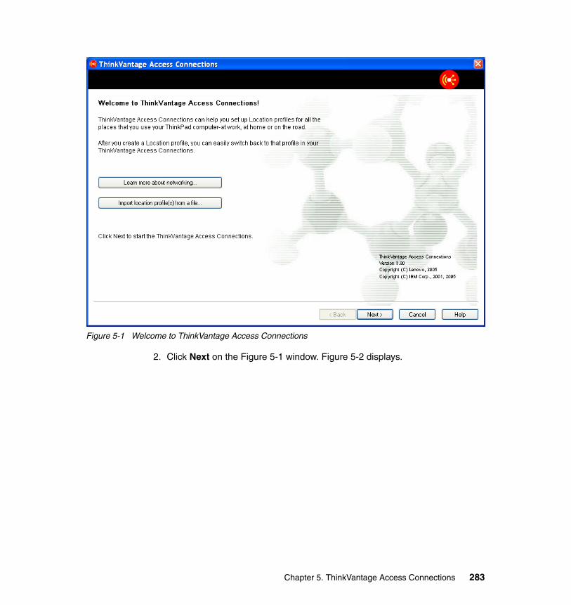
Figure 5-1 Welcome to ThinkVantage Access Connections
2. Click Next on the Figure 5-1 window. Figure 5-2 displays.
Chapter 5. ThinkVantage Access Connections 283
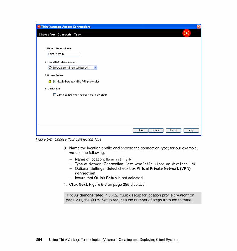
.
Figure 5-2 Choose Your Connection Type
3. Name the location profile and choose the connection type; for our example, we use the following:
– Name of location: Home with VPN– Type of Network Connection: Best Available Wired or Wireless LAN– Optional Settings: Select check box Virtual Private Network (VPN)
connection– Insure that Quick Setup is not selected
4. Click Next. Figure 5-3 on page 285 displays.
Tip: As demonstrated in 5.4.2, “Quick setup for location profile creation” on page 299, the Quick Setup reduces the number of steps from ten to three.
284 Using ThinkVantage Technologies: Volume 1 Creating and Deploying Client Systems
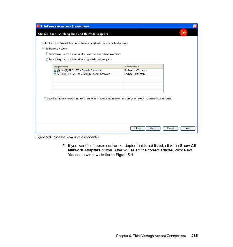
Figure 5-3 Choose your wireless adapter
5. If you want to choose a network adapter that is not listed, click the Show All Network Adapters button. After you select the correct adapter, click Next. You see a window similar to Figure 5-4.
Chapter 5. ThinkVantage Access Connections 285
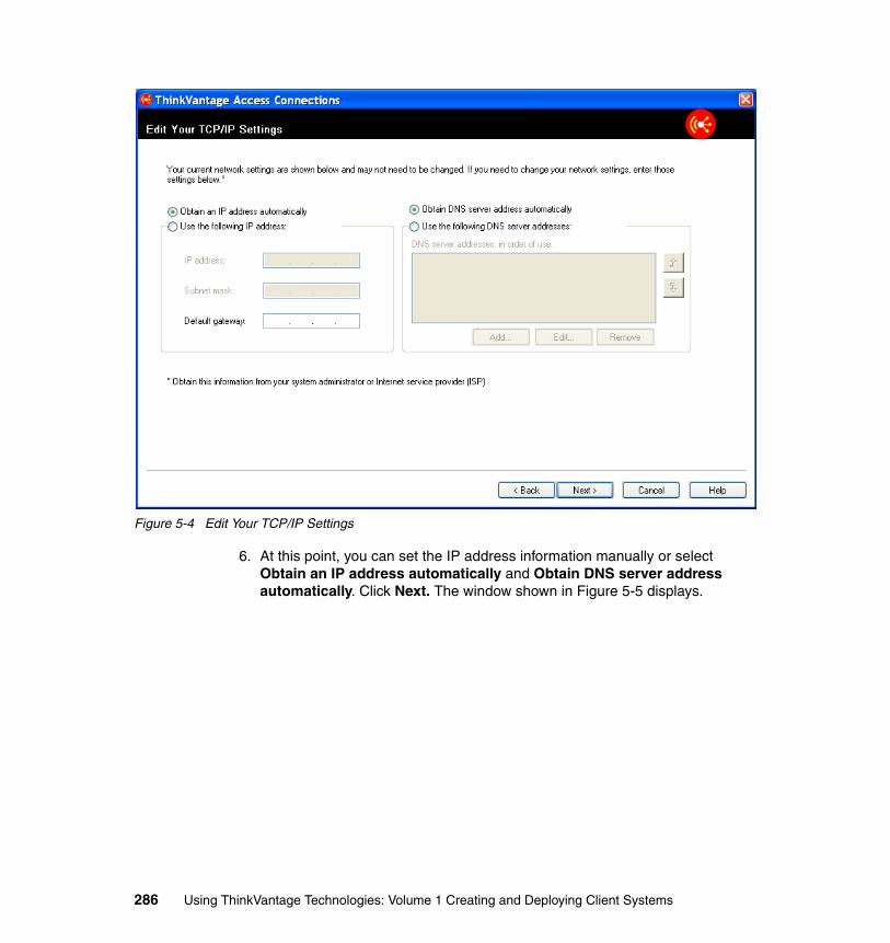
Figure 5-4 Edit Your TCP/IP Settings
6. At this point, you can set the IP address information manually or select Obtain an IP address automatically and Obtain DNS server address automatically. Click Next. The window shown in Figure 5-5 displays.
286 Using ThinkVantage Technologies: Volume 1 Creating and Deploying Client Systems
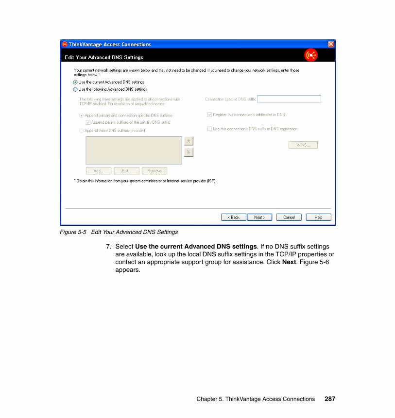
Figure 5-5 Edit Your Advanced DNS Settings
7. Select Use the current Advanced DNS settings. If no DNS suffix settings are available, look up the local DNS suffix settings in the TCP/IP properties or contact an appropriate support group for assistance. Click Next. Figure 5-6 appears.
Chapter 5. ThinkVantage Access Connections 287
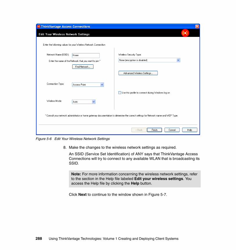
Figure 5-6 Edit Your Wireless Network Settings
8. Make the changes to the wireless network settings as required.
An SSID (Service Set Identification) of ANY says that ThinkVantage Access Connections will try to connect to any available WLAN that is broadcasting its SSID.
Click Next to continue to the window shown in Figure 5-7.
Note: For more information concerning the wireless network settings, refer to the section in the Help file labeled Edit your wireless settings. You access the Help file by clicking the Help button.
288 Using ThinkVantage Technologies: Volume 1 Creating and Deploying Client Systems
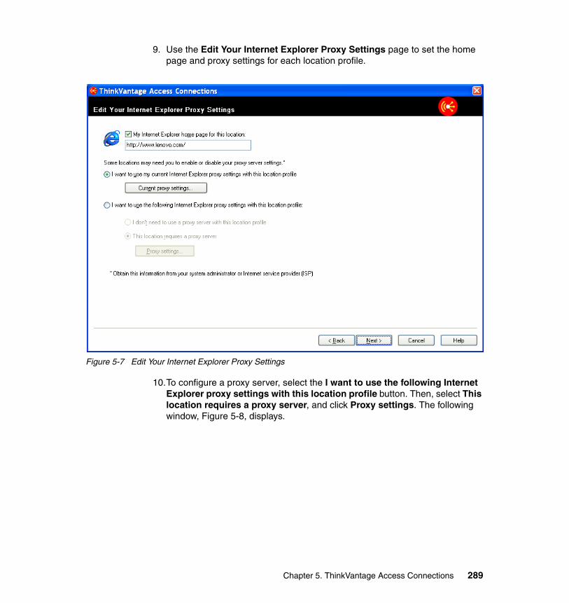
9. Use the Edit Your Internet Explorer Proxy Settings page to set the home page and proxy settings for each location profile.
Figure 5-7 Edit Your Internet Explorer Proxy Settings
10.To configure a proxy server, select the I want to use the following Internet Explorer proxy settings with this location profile button. Then, select This location requires a proxy server, and click Proxy settings. The following window, Figure 5-8, displays.
Chapter 5. ThinkVantage Access Connections 289
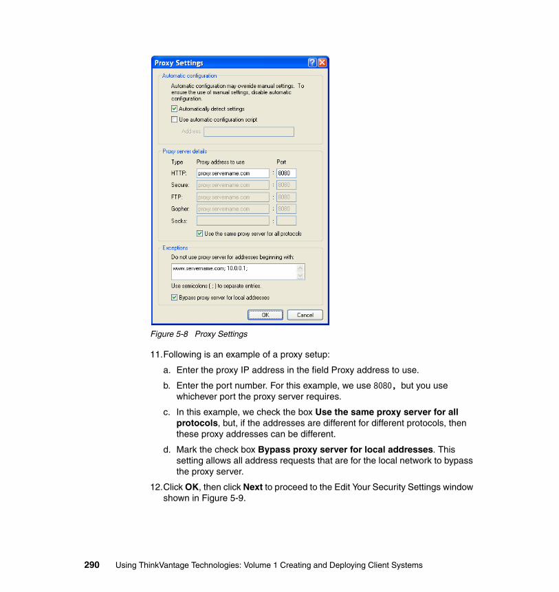
Figure 5-8 Proxy Settings
11.Following is an example of a proxy setup:
a. Enter the proxy IP address in the field Proxy address to use.
b. Enter the port number. For this example, we use 8080, but you use whichever port the proxy server requires.
c. In this example, we check the box Use the same proxy server for all protocols, but, if the addresses are different for different protocols, then these proxy addresses can be different.
d. Mark the check box Bypass proxy server for local addresses. This setting allows all address requests that are for the local network to bypass the proxy server.
12.Click OK, then click Next to proceed to the Edit Your Security Settings window shown in Figure 5-9.
290 Using ThinkVantage Technologies: Volume 1 Creating and Deploying Client Systems
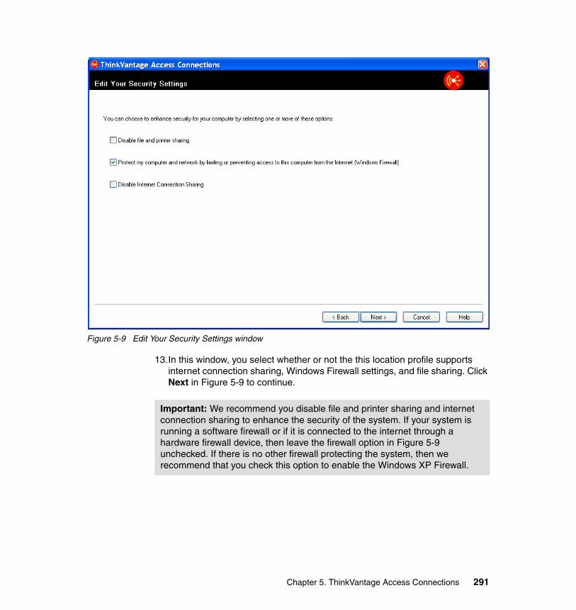
Figure 5-9 Edit Your Security Settings window
13.In this window, you select whether or not the this location profile supports internet connection sharing, Windows Firewall settings, and file sharing. Click Next in Figure 5-9 to continue.
Important: We recommend you disable file and printer sharing and internet connection sharing to enhance the security of the system. If your system is running a software firewall or if it is connected to the internet through a hardware firewall device, then leave the firewall option in Figure 5-9 unchecked. If there is no other firewall protecting the system, then we recommend that you check this option to enable the Windows XP Firewall.
Chapter 5. ThinkVantage Access Connections 291
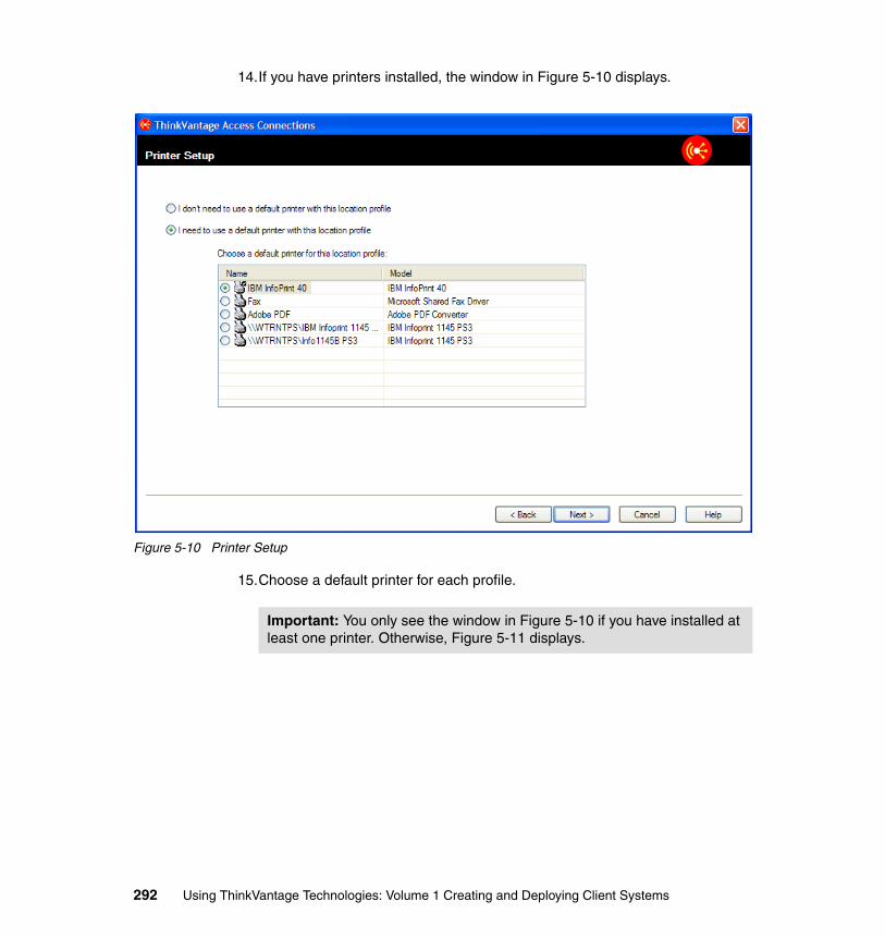
14.If you have printers installed, the window in Figure 5-10 displays.
Figure 5-10 Printer Setup
15.Choose a default printer for each profile.
Important: You only see the window in Figure 5-10 if you have installed at least one printer. Otherwise, Figure 5-11 displays.
292 Using ThinkVantage Technologies: Volume 1 Creating and Deploying Client Systems
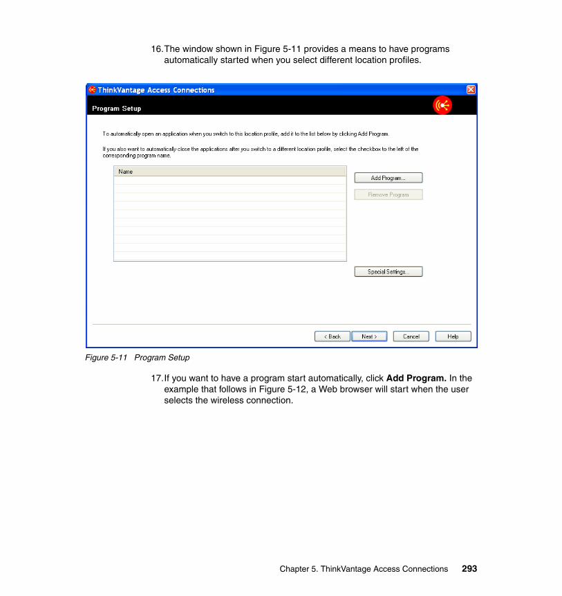
16.The window shown in Figure 5-11 provides a means to have programs automatically started when you select different location profiles.
Figure 5-11 Program Setup
17.If you want to have a program start automatically, click Add Program. In the example that follows in Figure 5-12, a Web browser will start when the user selects the wireless connection.
Chapter 5. ThinkVantage Access Connections 293
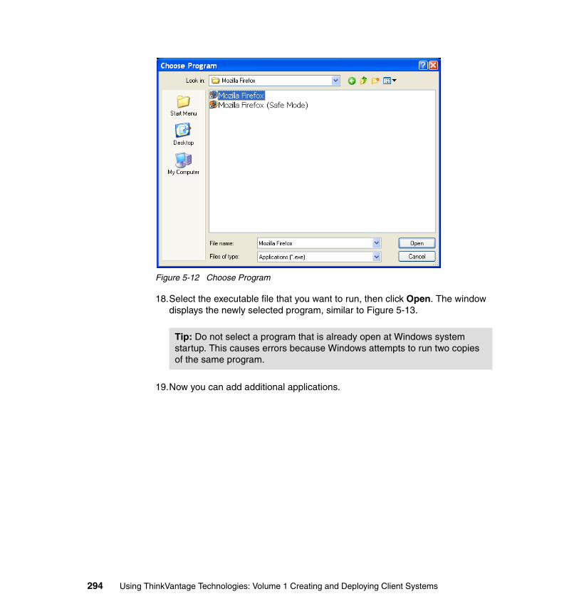
Figure 5-12 Choose Program
18.Select the executable file that you want to run, then click Open. The window displays the newly selected program, similar to Figure 5-13.
19.Now you can add additional applications.
Tip: Do not select a program that is already open at Windows system startup. This causes errors because Windows attempts to run two copies of the same program.
294 Using ThinkVantage Technologies: Volume 1 Creating and Deploying Client Systems
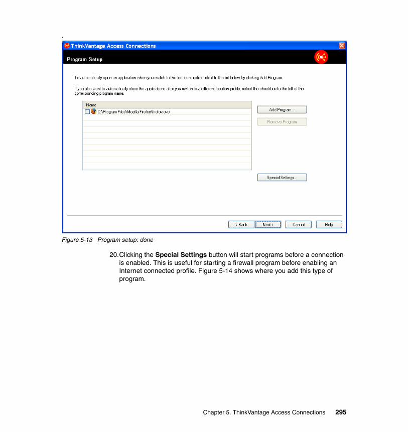
.
Figure 5-13 Program setup: done
20.Clicking the Special Settings button will start programs before a connection is enabled. This is useful for starting a firewall program before enabling an Internet connected profile. Figure 5-14 shows where you add this type of program.
Chapter 5. ThinkVantage Access Connections 295
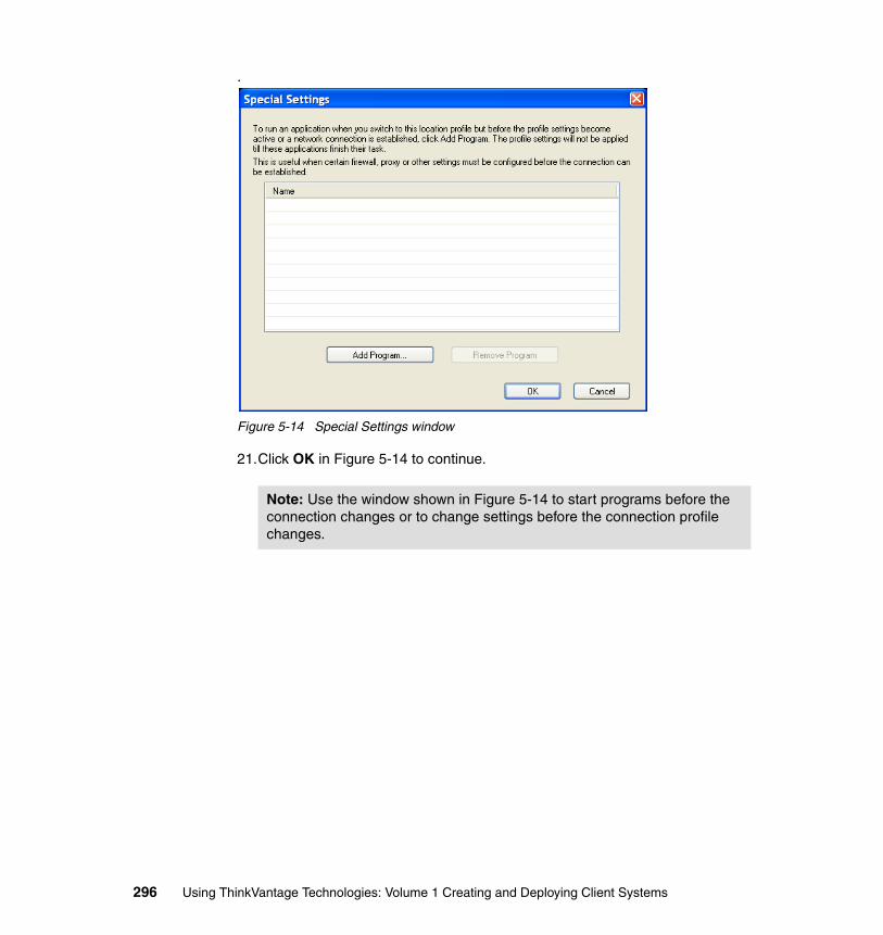
.
Figure 5-14 Special Settings window
21.Click OK in Figure 5-14 to continue.
Note: Use the window shown in Figure 5-14 to start programs before the connection changes or to change settings before the connection profile changes.
296 Using ThinkVantage Technologies: Volume 1 Creating and Deploying Client Systems
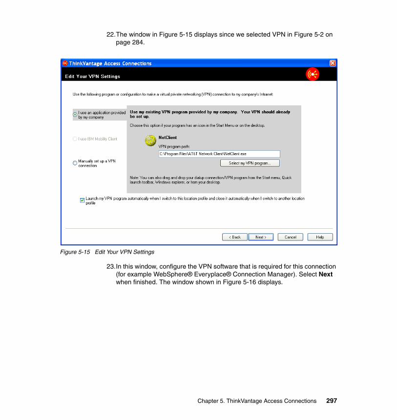
22.The window in Figure 5-15 displays since we selected VPN in Figure 5-2 on page 284.
Figure 5-15 Edit Your VPN Settings
23.In this window, configure the VPN software that is required for this connection (for example WebSphere® Everyplace® Connection Manager). Select Next when finished. The window shown in Figure 5-16 displays.
Chapter 5. ThinkVantage Access Connections 297
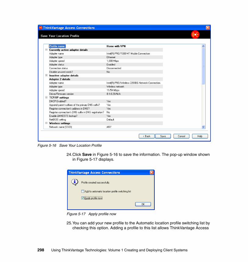
Figure 5-16 Save Your Location Profile
24.Click Save in Figure 5-16 to save the information. The pop-up window shown in Figure 5-17 displays.
Figure 5-17 Apply profile now
25.You can add your new profile to the Automatic location profile switching list by checking this option. Adding a profile to this list allows ThinkVantage Access
298 Using ThinkVantage Technologies: Volume 1 Creating and Deploying Client Systems
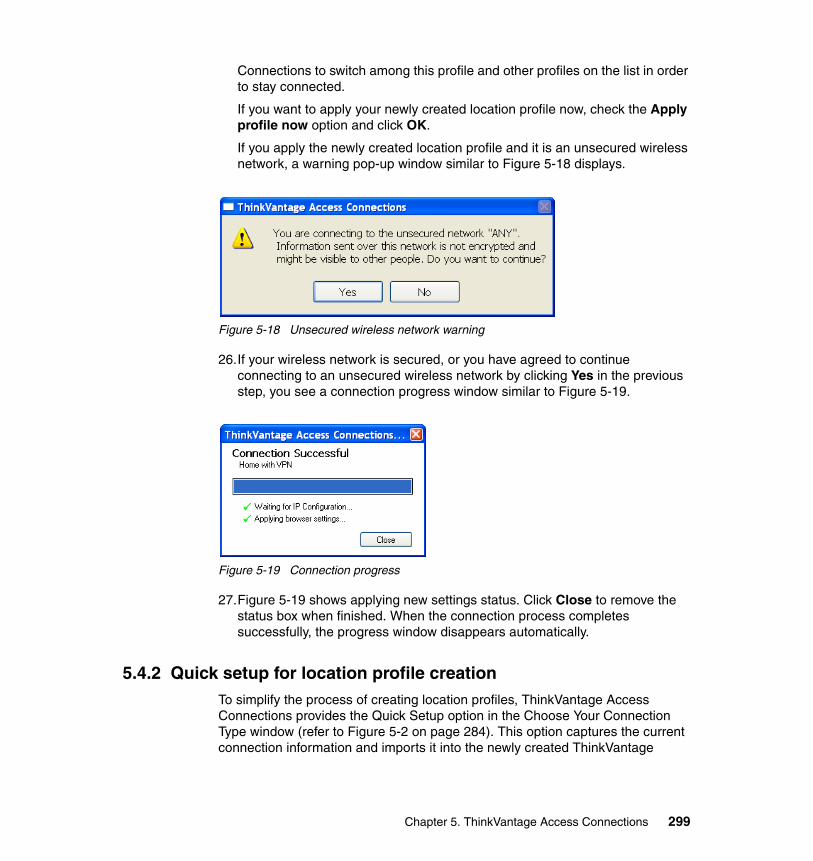
Connections to switch among this profile and other profiles on the list in order to stay connected.
If you want to apply your newly created location profile now, check the Apply profile now option and click OK.
If you apply the newly created location profile and it is an unsecured wireless network, a warning pop-up window similar to Figure 5-18 displays.
Figure 5-18 Unsecured wireless network warning
26.If your wireless network is secured, or you have agreed to continue connecting to an unsecured wireless network by clicking Yes in the previous step, you see a connection progress window similar to Figure 5-19.
Figure 5-19 Connection progress
27.Figure 5-19 shows applying new settings status. Click Close to remove the status box when finished. When the connection process completes successfully, the progress window disappears automatically.
5.4.2 Quick setup for location profile creationTo simplify the process of creating location profiles, ThinkVantage Access Connections provides the Quick Setup option in the Choose Your Connection Type window (refer to Figure 5-2 on page 284). This option captures the current connection information and imports it into the newly created ThinkVantage
Chapter 5. ThinkVantage Access Connections 299
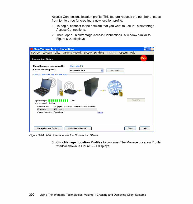
Access Connections location profile. This feature reduces the number of steps from ten to three for creating a new location profile.
1. To begin, connect to the network that you want to use in ThinkVantage Access Connections.
2. Then, open ThinkVantage Access Connections. A window similar to Figure 5-20 displays.
Figure 5-20 Main interface window Connection Status
3. Click Manage Location Profiles to continue. The Manage Location Profile window shown in Figure 5-21 displays.
300 Using ThinkVantage Technologies: Volume 1 Creating and Deploying Client Systems
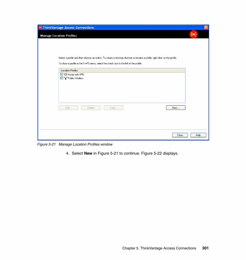
Figure 5-21 Manage Location Profiles window
4. Select New in Figure 5-21 to continue. Figure 5-22 displays.
Chapter 5. ThinkVantage Access Connections 301
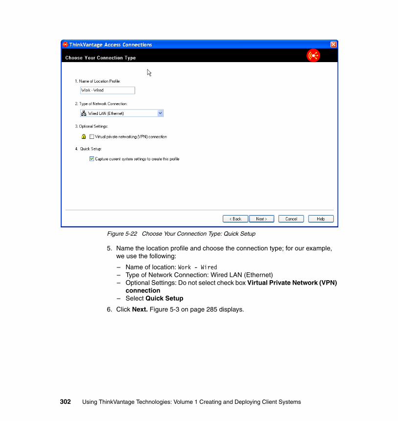
Figure 5-22 Choose Your Connection Type: Quick Setup
5. Name the location profile and choose the connection type; for our example, we use the following:
– Name of location: Work - Wired– Type of Network Connection: Wired LAN (Ethernet)– Optional Settings: Do not select check box Virtual Private Network (VPN)
connection– Select Quick Setup
6. Click Next. Figure 5-3 on page 285 displays.
302 Using ThinkVantage Technologies: Volume 1 Creating and Deploying Client Systems
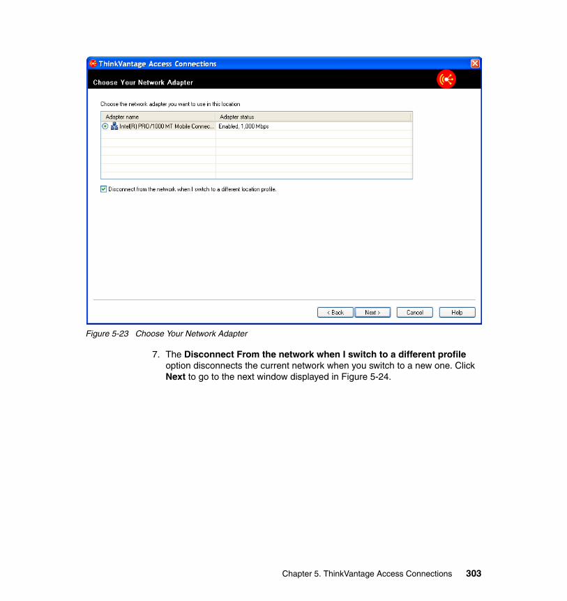
Figure 5-23 Choose Your Network Adapter
7. The Disconnect From the network when I switch to a different profile option disconnects the current network when you switch to a new one. Click Next to go to the next window displayed in Figure 5-24.
Chapter 5. ThinkVantage Access Connections 303
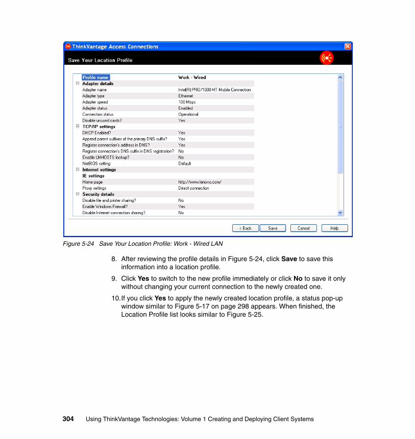
Figure 5-24 Save Your Location Profile: Work - Wired LAN
8. After reviewing the profile details in Figure 5-24, click Save to save this information into a location profile.
9. Click Yes to switch to the new profile immediately or click No to save it only without changing your current connection to the newly created one.
10.If you click Yes to apply the newly created location profile, a status pop-up window similar to Figure 5-17 on page 298 appears. When finished, the Location Profile list looks similar to Figure 5-25.
304 Using ThinkVantage Technologies: Volume 1 Creating and Deploying Client Systems
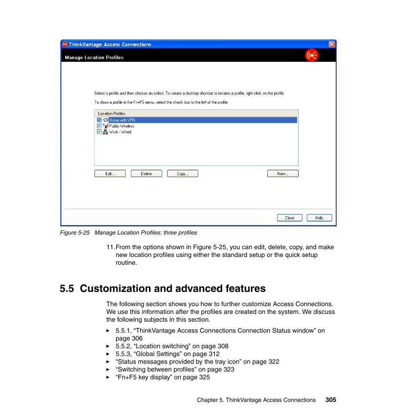
Figure 5-25 Manage Location Profiles: three profiles
11.From the options shown in Figure 5-25, you can edit, delete, copy, and make new location profiles using either the standard setup or the quick setup routine.
5.5 Customization and advanced featuresThe following section shows you how to further customize Access Connections. We use this information after the profiles are created on the system. We discuss the following subjects in this section.
� 5.5.1, “ThinkVantage Access Connections Connection Status window” on page 306
� 5.5.2, “Location switching” on page 308� 5.5.3, “Global Settings” on page 312� “Status messages provided by the tray icon” on page 322� “Switching between profiles” on page 323� “Fn+F5 key display” on page 325
Chapter 5. ThinkVantage Access Connections 305
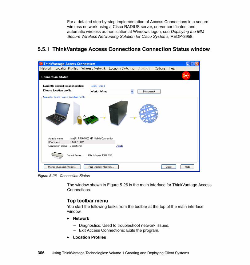
For a detailed step-by-step implementation of Access Connections in a secure wireless network using a Cisco RADIUS server, server certificates, and automatic wireless authentication at Windows logon, see Deploying the IBM Secure Wireless Networking Solution for Cisco Systems, REDP-3958.
5.5.1 ThinkVantage Access Connections Connection Status window
Figure 5-26 Connection Status
The window shown in Figure 5-26 is the main interface for ThinkVantage Access Connections.
Top toolbar menuYou start the following tasks from the toolbar at the top of the main interface window.
� Network
– Diagnostics: Used to troubleshoot network issues.– Exit Access Connections: Exits the program.
� Location Profiles
306 Using ThinkVantage Technologies: Volume 1 Creating and Deploying Client Systems
– Create New Profile: Launches the location profile creation wizard.– Disconnect Current Profile: Disconnects the system from the current
location profile.– Manage Profiles: Opens the manage profile interface window. For more
details about this subject, go to section 5.5.5, “Managing Location Profiles” on page 314.
– Export Profiles: Creates a location profile .loc file containing the profiles that are currently configured on the system.
� Wireless Network
– Enable Wireless Radio: Turns on the wireless radio that is configured for the current location profile.
– Find Wireless Networks: Scans for available wireless networks. More information is given about this in 5.6, “Enabler for Administrator Profile Deployment Feature” on page 329.
– Disable All Wireless Radios: Turns off all wireless radios on this system.
� Location Switching
– Switch Ethernet and Wireless Location Profiles Automatically: Opens the Location Switching configuration window. This feature is discussed in greater detail in the section titled 5.5.2, “Location switching” on page 308.
� Bluetooth
– Enable Bluetooth Radio: Enables the system’s Bluetooth Radio.– Launch Bluetooth Places: Opens the Windows Explorer folder that
contains the Bluetooth Places folder.– Bluetooth Security: Opens the Bluetooth Security submenu.
• High• Medium• Low• None• Customize
– Bluetooth Security Help: Opens the ThinkVantage Access Connections Help to the Bluetooth Security section.
� Options
– Global Settings: Details of these settings are in the section titled 5.5.3, “Global Settings” on page 312.
– Preferences: Permits you to customize sound and animations.
� Help
– Help: Opens the ThinkVantage Access Connections Help file as shown in Figure 5-7 on page 289.
– About: Displays the ThinkVantage Access Connections version information.
Chapter 5. ThinkVantage Access Connections 307
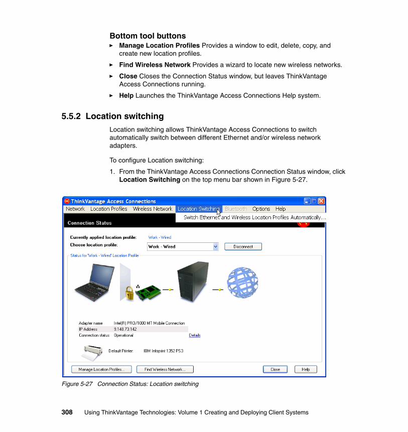
Bottom tool buttons� Manage Location Profiles Provides a window to edit, delete, copy, and
create new location profiles.
� Find Wireless Network Provides a wizard to locate new wireless networks.
� Close Closes the Connection Status window, but leaves ThinkVantage Access Connections running.
� Help Launches the ThinkVantage Access Connections Help system.
5.5.2 Location switchingLocation switching allows ThinkVantage Access Connections to switch automatically switch between different Ethernet and/or wireless network adapters.
To configure Location switching:
1. From the ThinkVantage Access Connections Connection Status window, click Location Switching on the top menu bar shown in Figure 5-27.
Figure 5-27 Connection Status: Location switching
308 Using ThinkVantage Technologies: Volume 1 Creating and Deploying Client Systems
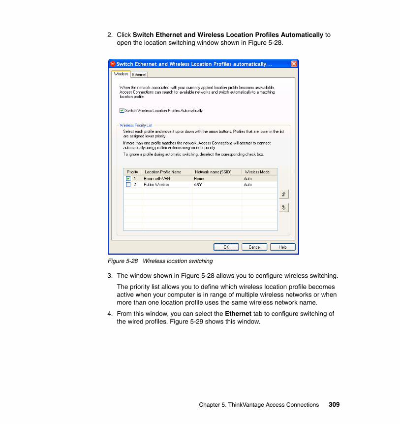
2. Click Switch Ethernet and Wireless Location Profiles Automatically to open the location switching window shown in Figure 5-28.
Figure 5-28 Wireless location switching
3. The window shown in Figure 5-28 allows you to configure wireless switching.
The priority list allows you to define which wireless location profile becomes active when your computer is in range of multiple wireless networks or when more than one location profile uses the same wireless network name.
4. From this window, you can select the Ethernet tab to configure switching of the wired profiles. Figure 5-29 shows this window.
Chapter 5. ThinkVantage Access Connections 309
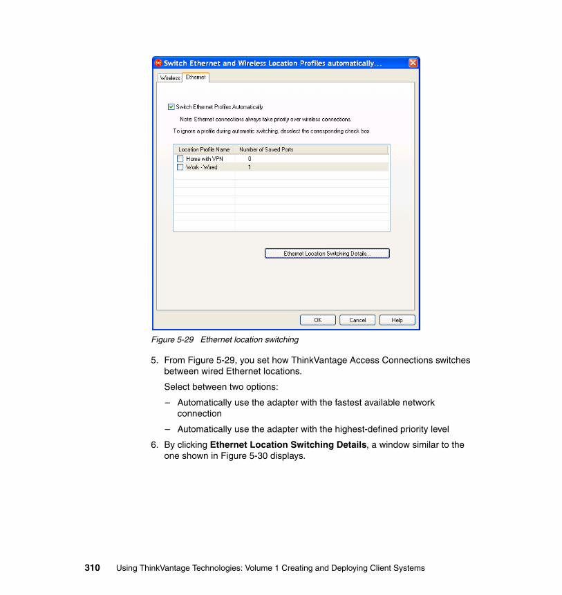
Figure 5-29 Ethernet location switching
5. From Figure 5-29, you set how ThinkVantage Access Connections switches between wired Ethernet locations.
Select between two options:
– Automatically use the adapter with the fastest available network connection
– Automatically use the adapter with the highest-defined priority level
6. By clicking Ethernet Location Switching Details, a window similar to the one shown in Figure 5-30 displays.
310 Using ThinkVantage Technologies: Volume 1 Creating and Deploying Client Systems
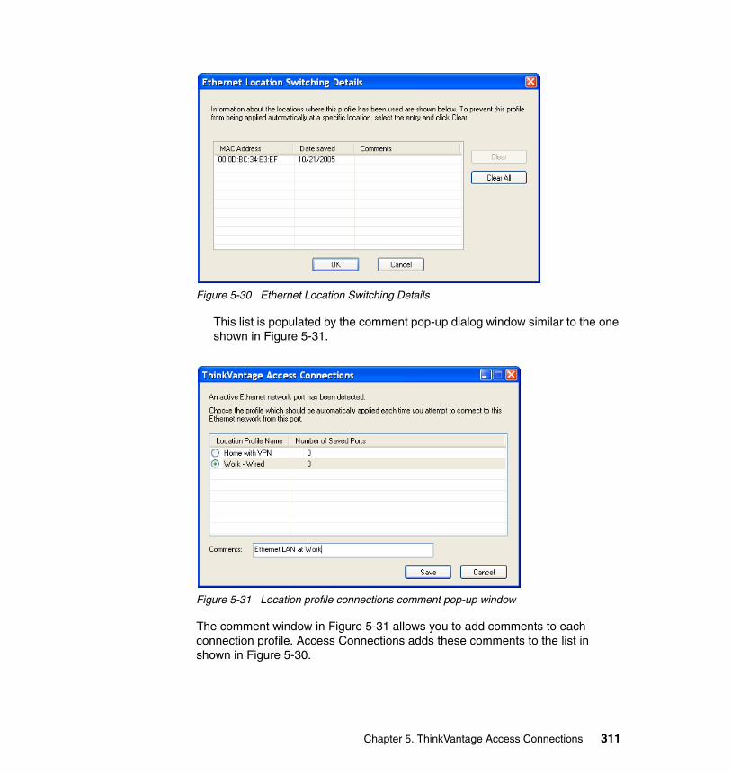
Figure 5-30 Ethernet Location Switching Details
This list is populated by the comment pop-up dialog window similar to the one shown in Figure 5-31.
Figure 5-31 Location profile connections comment pop-up window
The comment window in Figure 5-31 allows you to add comments to each connection profile. Access Connections adds these comments to the list in shown in Figure 5-30.
Chapter 5. ThinkVantage Access Connections 311
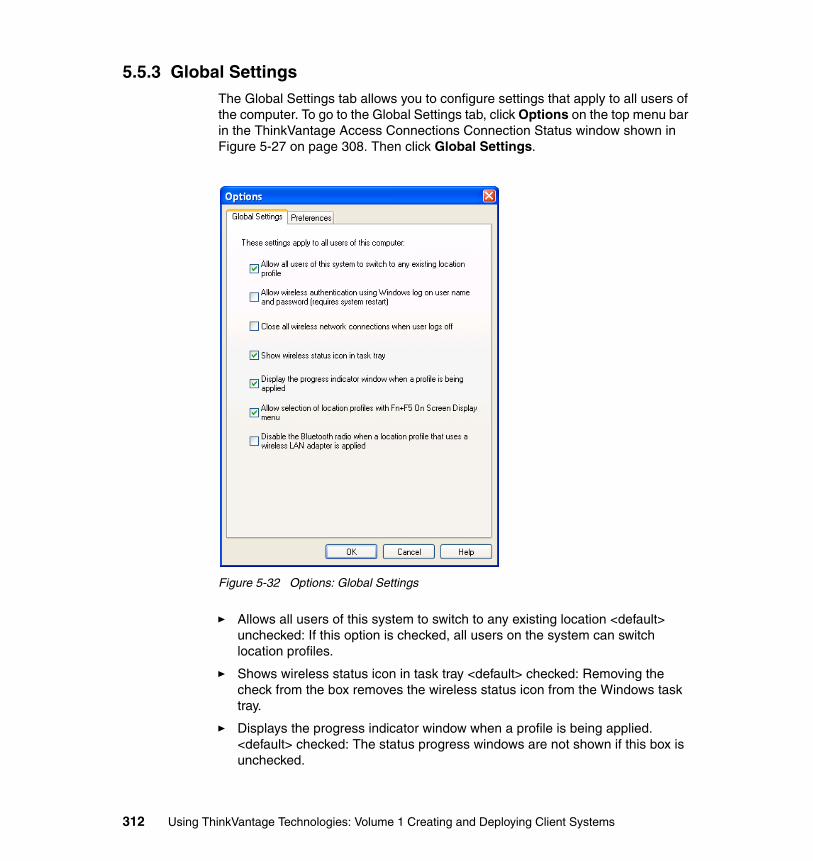
5.5.3 Global SettingsThe Global Settings tab allows you to configure settings that apply to all users of the computer. To go to the Global Settings tab, click Options on the top menu bar in the ThinkVantage Access Connections Connection Status window shown in Figure 5-27 on page 308. Then click Global Settings.
Figure 5-32 Options: Global Settings
� Allows all users of this system to switch to any existing location <default> unchecked: If this option is checked, all users on the system can switch location profiles.
� Shows wireless status icon in task tray <default> checked: Removing the check from the box removes the wireless status icon from the Windows task tray.
� Displays the progress indicator window when a profile is being applied. <default> checked: The status progress windows are not shown if this box is unchecked.
312 Using ThinkVantage Technologies: Volume 1 Creating and Deploying Client Systems
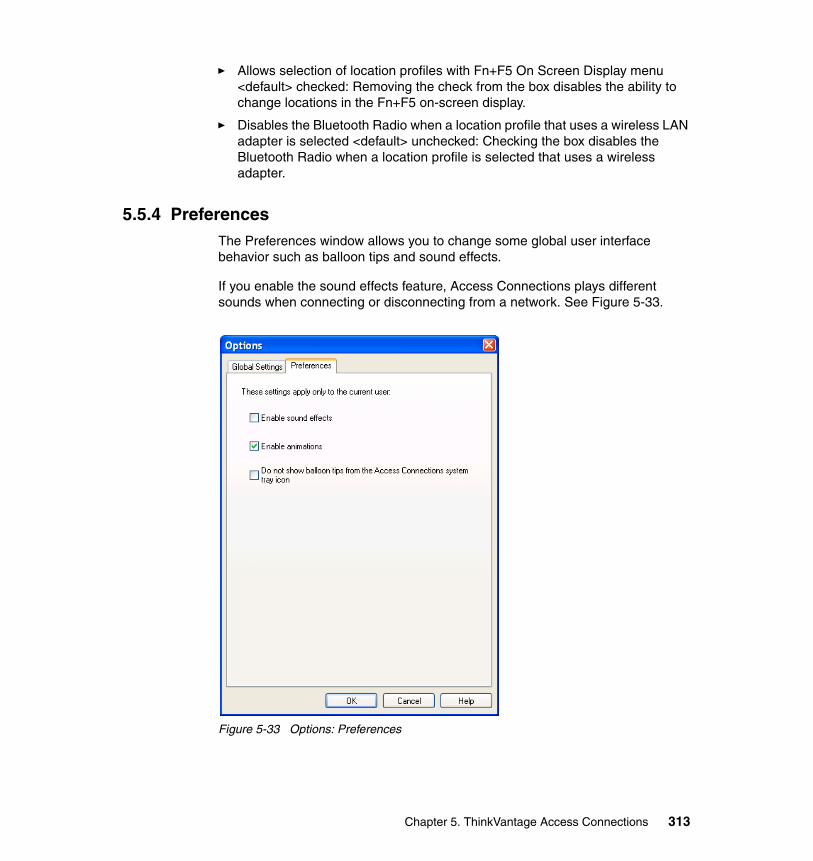
� Allows selection of location profiles with Fn+F5 On Screen Display menu <default> checked: Removing the check from the box disables the ability to change locations in the Fn+F5 on-screen display.
� Disables the Bluetooth Radio when a location profile that uses a wireless LAN adapter is selected <default> unchecked: Checking the box disables the Bluetooth Radio when a location profile is selected that uses a wireless adapter.
5.5.4 PreferencesThe Preferences window allows you to change some global user interface behavior such as balloon tips and sound effects.
If you enable the sound effects feature, Access Connections plays different sounds when connecting or disconnecting from a network. See Figure 5-33.
Figure 5-33 Options: Preferences
Chapter 5. ThinkVantage Access Connections 313
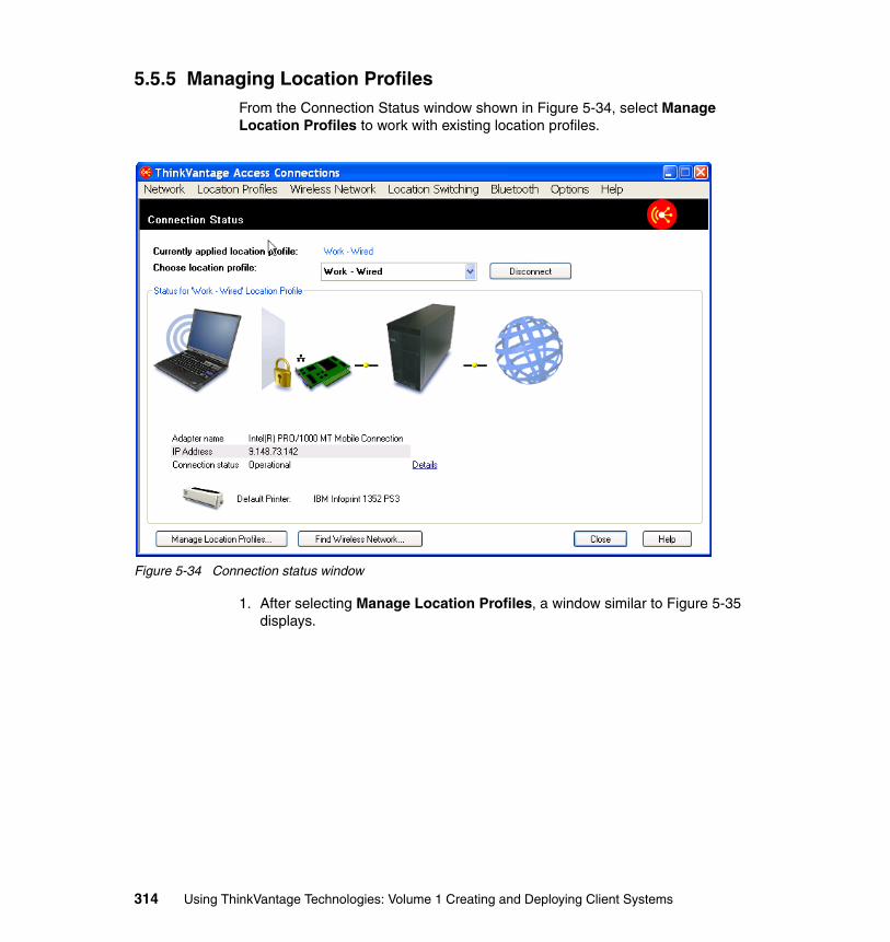
5.5.5 Managing Location ProfilesFrom the Connection Status window shown in Figure 5-34, select Manage Location Profiles to work with existing location profiles.
Figure 5-34 Connection status window
1. After selecting Manage Location Profiles, a window similar to Figure 5-35 displays.
314 Using ThinkVantage Technologies: Volume 1 Creating and Deploying Client Systems
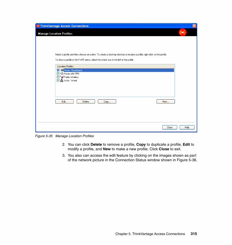
Figure 5-35 Manage Location Profiles
2. You can click Delete to remove a profile, Copy to duplicate a profile, Edit to modify a profile, and New to make a new profile. Click Close to exit.
3. You also can access the edit feature by clicking on the images shown as part of the network picture in the Connection Status window shown in Figure 5-36.
Chapter 5. ThinkVantage Access Connections 315
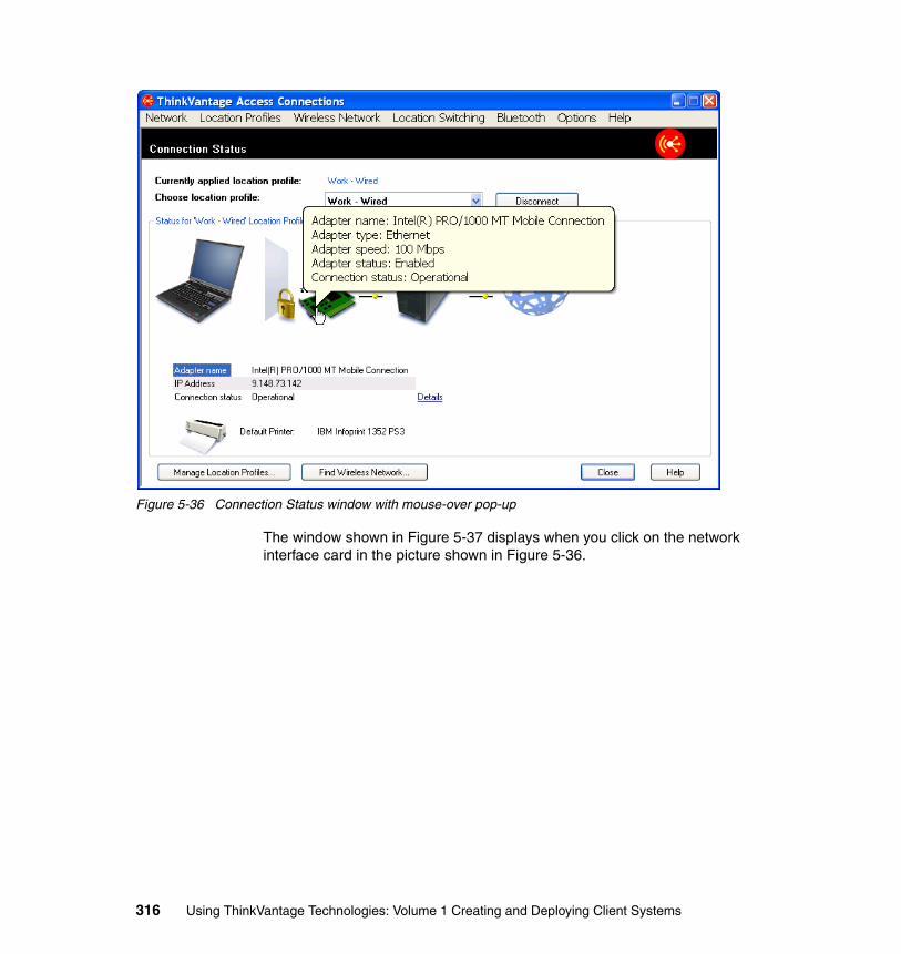
Figure 5-36 Connection Status window with mouse-over pop-up
The window shown in Figure 5-37 displays when you click on the network interface card in the picture shown in Figure 5-36.
316 Using ThinkVantage Technologies: Volume 1 Creating and Deploying Client Systems
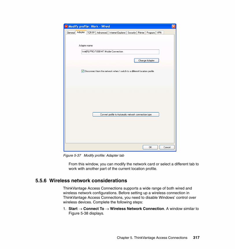
Figure 5-37 Modify profile: Adapter tab
From this window, you can modify the network card or select a different tab to work with another part of the current location profile.
5.5.6 Wireless network considerationsThinkVantage Access Connections supports a wide range of both wired and wireless network configurations. Before setting up a wireless connection in ThinkVantage Access Connections, you need to disable Windows’ control over wireless devices. Complete the following steps:
1. Start → Connect To → Wireless Network Connection. A window similar to Figure 5-38 displays.
Chapter 5. ThinkVantage Access Connections 317
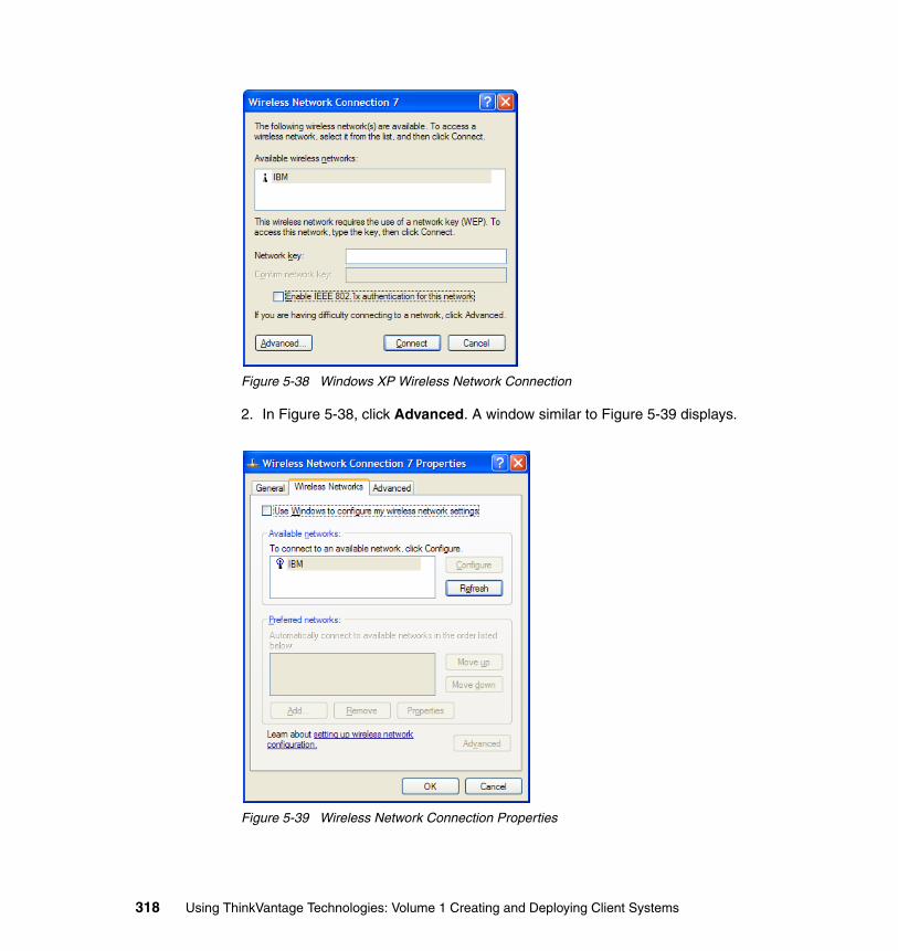
Figure 5-38 Windows XP Wireless Network Connection
2. In Figure 5-38, click Advanced. A window similar to Figure 5-39 displays.
Figure 5-39 Wireless Network Connection Properties
318 Using ThinkVantage Technologies: Volume 1 Creating and Deploying Client Systems
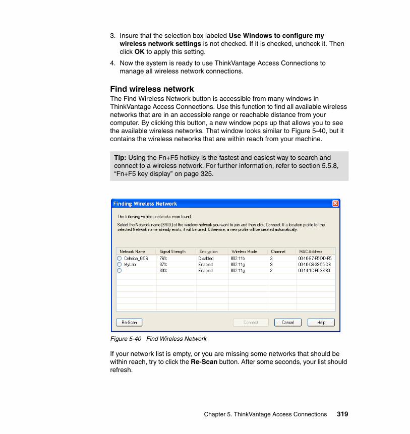
3. Insure that the selection box labeled Use Windows to configure my wireless network settings is not checked. If it is checked, uncheck it. Then click OK to apply this setting.
4. Now the system is ready to use ThinkVantage Access Connections to manage all wireless network connections.
Find wireless networkThe Find Wireless Network button is accessible from many windows in ThinkVantage Access Connections. Use this function to find all available wireless networks that are in an accessible range or reachable distance from your computer. By clicking this button, a new window pops up that allows you to see the available wireless networks. That window looks similar to Figure 5-40, but it contains the wireless networks that are within reach from your machine.
Figure 5-40 Find Wireless Network
If your network list is empty, or you are missing some networks that should be within reach, try to click the Re-Scan button. After some seconds, your list should refresh.
Tip: Using the Fn+F5 hotkey is the fastest and easiest way to search and connect to a wireless network. For further information, refer to section 5.5.8, “Fn+F5 key display” on page 325.
Chapter 5. ThinkVantage Access Connections 319
This menu contains all WLANs, including the ones for which you already have a profile. If you select a wireless network that already has a profile, it tries to use the existing profile and not make a new one.
This menu contains facts about the different reachable networks:
� Network Name
This is the SSID (Service Set Identification) of the WLAN to which you are connecting. If you try to connect to an access point that has its SSID broadcast-disabled, you need to set up the profile manually. If you have a profile for the WLAN from before (even though the SSID broadcast is disabled), it uses the existing profile.
An SSID is a 32-character unique identifier attached to the header of packets sent over a WLAN that acts as a password when a mobile device tries to connect to the wireless access point. The SSID differentiates one WLAN from another, so all access points and all devices attempting to connect to a specific WLAN must use the same SSID. A device is not permitted to join the WLAN unless it can provide the unique SSID.
An SSID is also referred to as a network name because essentially it is a name that identifies a wireless network.
� Wireless Mode
This field describes at what wireless mode that access point is running. Available speeds are 802.11b, 802.11a, and 802.11g.
� MAC Address
This field tells you the MAC address of the wireless access point. If you are in doubt of what access point it really is, you can compare this MAC address with the actual address of the access point.
� Encryption
This field tells you if the access point is encrypted. If encryption is enabled, you have to make the profile manually and add the required authentication to that profile. If you try to connect to a WLAN with encryption enabled and there is no existing profile for it, you get a message that looks like Figure 5-41 on page 321.
320 Using ThinkVantage Technologies: Volume 1 Creating and Deploying Client Systems
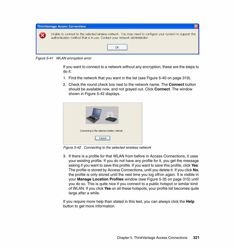
Figure 5-41 WLAN encryption error
If you want to connect to a network without any encryption, these are the steps to do it:
1. Find the network that you want in the list (see Figure 5-40 on page 319).
2. Check the round check box next to the network name. The Connect button should be available now, and not grayed out. Click Connect. The window shown in Figure 5-42 displays.
Figure 5-42 Connecting to the selected wireless network
3. If there is a profile for that WLAN from before in Access Connections, it uses your existing profile. If you do not have any profile for it, you get the message asking if you want to save this profile. If you want to save this profile, click Yes. The profile is stored by Access Connections, until you delete it. If you click No, the profile is only stored until the next time you log off/on again. It is visible in your Manage Location Profiles window (see Figure 5-35 on page 315) until you do so. This is quite nice if you connect to a public hotspot or similar kind of WLAN. If you click Yes on all these hotspots, your profile list becomes quite large after a while.
If you require more help than stated in this text, you can always click the Help button to get more information.
Chapter 5. ThinkVantage Access Connections 321
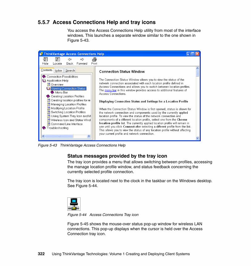
5.5.7 Access Connections Help and tray iconsYou access the Access Connections Help utility from most of the interface windows. This launches a separate window similar to the one shown in Figure 5-43.
Figure 5-43 ThinkVantage Access Connections Help
Status messages provided by the tray iconThe tray icon provides a menu that allows switching between profiles, accessing the manage location profile window, and status feedback concerning the currently selected profile connection.
The tray icon is located next to the clock in the taskbar on the Windows desktop. See Figure 5-44.
Figure 5-44 Access Connections Tray icon
Figure 5-45 shows the mouse-over status pop-up window for wireless LAN connections. This pop-up displays when the cursor is held over the Access Connection tray icon.
322 Using ThinkVantage Technologies: Volume 1 Creating and Deploying Client Systems
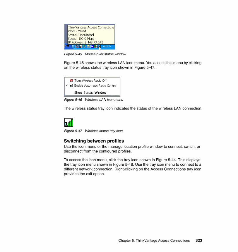
Figure 5-45 Mouse-over status window
Figure 5-46 shows the wireless LAN icon menu. You access this menu by clicking on the wireless status tray icon shown in Figure 5-47.
Figure 5-46 Wireless LAN icon menu
The wireless status tray icon indicates the status of the wireless LAN connection.
Figure 5-47 Wireless status tray icon
Switching between profilesUse the icon menu or the manage location profile window to connect, switch, or disconnect from the configured profiles.
To access the icon menu, click the tray icon shown in Figure 5-44. This displays the tray icon menu shown in Figure 5-48. Use the tray icon menu to connect to a different network connection. Right-clicking on the Access Connections tray icon provides the exit option.
Chapter 5. ThinkVantage Access Connections 323
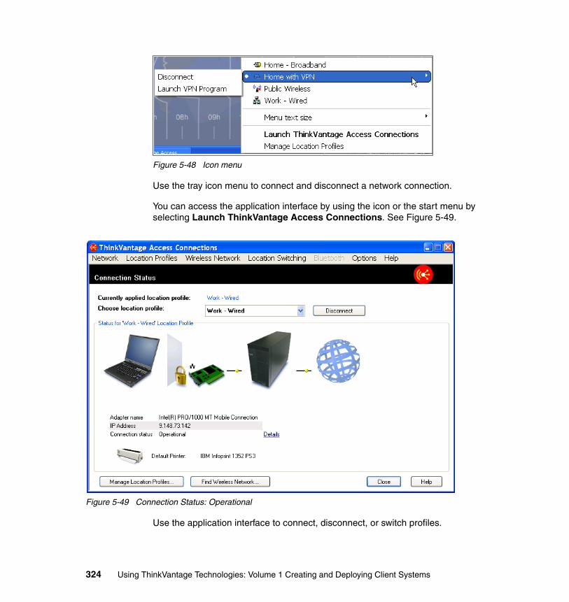
Figure 5-48 Icon menu
Use the tray icon menu to connect and disconnect a network connection.
You can access the application interface by using the icon or the start menu by selecting Launch ThinkVantage Access Connections. See Figure 5-49.
Figure 5-49 Connection Status: Operational
Use the application interface to connect, disconnect, or switch profiles.
324 Using ThinkVantage Technologies: Volume 1 Creating and Deploying Client Systems
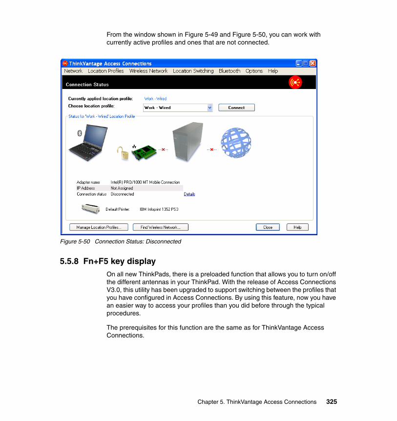
From the window shown in Figure 5-49 and Figure 5-50, you can work with currently active profiles and ones that are not connected.
Figure 5-50 Connection Status: Disconnected
5.5.8 Fn+F5 key displayOn all new ThinkPads, there is a preloaded function that allows you to turn on/off the different antennas in your ThinkPad. With the release of Access Connections V3.0, this utility has been upgraded to support switching between the profiles that you have configured in Access Connections. By using this feature, now you have an easier way to access your profiles than you did before through the typical procedures.
The prerequisites for this function are the same as for ThinkVantage Access Connections.
Chapter 5. ThinkVantage Access Connections 325
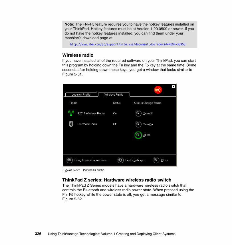
Wireless radioIf you have installed all of the required software on your ThinkPad, you can start this program by holding down the Fn key and the F5 key at the same time. Some seconds after holding down these keys, you get a window that looks similar to Figure 5-51.
Figure 5-51 Wireless radio
ThinkPad Z series: Hardware wireless radio switchThe ThinkPad Z Series models have a hardware wireless radio switch that controls the Bluetooth and wireless radio power state. When pressed using the Fn+F5 hotkey while the power state is off, you get a message similar to Figure 5-52.
Note: The FN+F5 feature requires you to have the hotkey features installed on your ThinkPad. Hotkey features must be at Version 1.20.0509 or newer. If you do not have the hotkey features installed, you can find them under your machine’s download page at:
http://www.ibm.com/pc/support/site.wss/document.do?lndocid=MIGR-38953
326 Using ThinkVantage Technologies: Volume 1 Creating and Deploying Client Systems
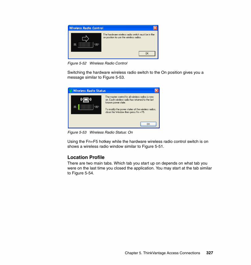
Figure 5-52 Wireless Radio Control
Switching the hardware wireless radio switch to the On position gives you a message similar to Figure 5-53.
Figure 5-53 Wireless Radio Status: On
Using the Fn+F5 hotkey while the hardware wireless radio control switch is on shows a wireless radio window similar to Figure 5-51.
Location ProfileThere are two main tabs. Which tab you start up on depends on what tab you were on the last time you closed the application. You may start at the tab similar to Figure 5-54.
Chapter 5. ThinkVantage Access Connections 327
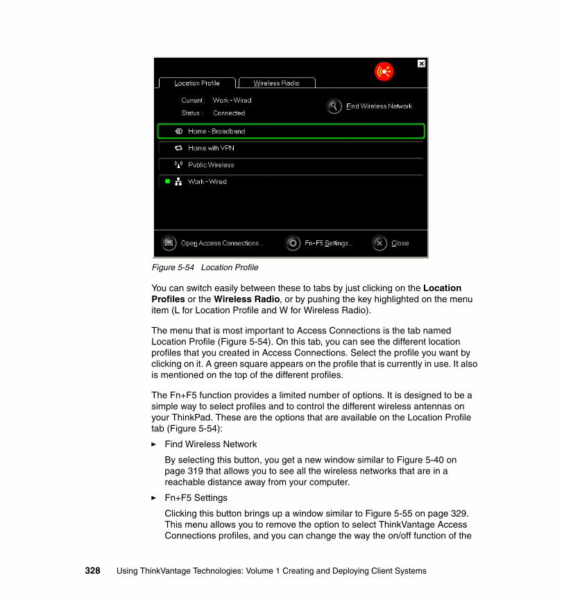
Figure 5-54 Location Profile
You can switch easily between these to tabs by just clicking on the Location Profiles or the Wireless Radio, or by pushing the key highlighted on the menu item (L for Location Profile and W for Wireless Radio).
The menu that is most important to Access Connections is the tab named Location Profile (Figure 5-54). On this tab, you can see the different location profiles that you created in Access Connections. Select the profile you want by clicking on it. A green square appears on the profile that is currently in use. It also is mentioned on the top of the different profiles.
The Fn+F5 function provides a limited number of options. It is designed to be a simple way to select profiles and to control the different wireless antennas on your ThinkPad. These are the options that are available on the Location Profile tab (Figure 5-54):
� Find Wireless Network
By selecting this button, you get a new window similar to Figure 5-40 on page 319 that allows you to see all the wireless networks that are in a reachable distance away from your computer.
� Fn+F5 Settings
Clicking this button brings up a window similar to Figure 5-55 on page 329. This menu allows you to remove the option to select ThinkVantage Access Connections profiles, and you can change the way the on/off function of the
328 Using ThinkVantage Technologies: Volume 1 Creating and Deploying Client Systems
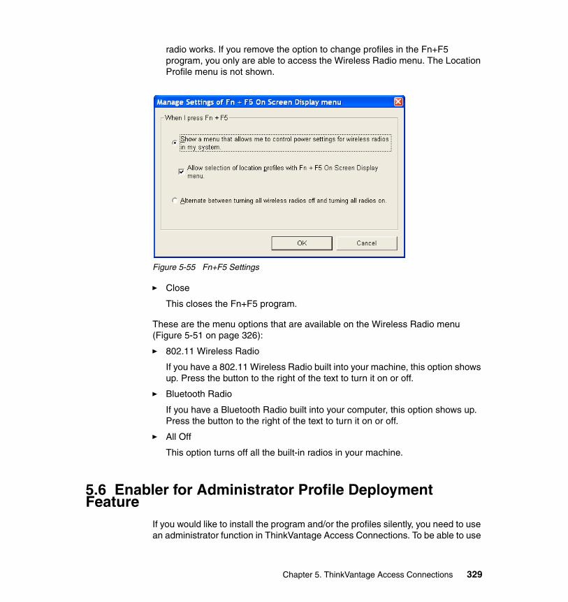
radio works. If you remove the option to change profiles in the Fn+F5 program, you only are able to access the Wireless Radio menu. The Location Profile menu is not shown.
Figure 5-55 Fn+F5 Settings
� Close
This closes the Fn+F5 program.
These are the menu options that are available on the Wireless Radio menu (Figure 5-51 on page 326):
� 802.11 Wireless Radio
If you have a 802.11 Wireless Radio built into your machine, this option shows up. Press the button to the right of the text to turn it on or off.
� Bluetooth Radio
If you have a Bluetooth Radio built into your computer, this option shows up. Press the button to the right of the text to turn it on or off.
� All Off
This option turns off all the built-in radios in your machine.
5.6 Enabler for Administrator Profile Deployment Feature
If you would like to install the program and/or the profiles silently, you need to use an administrator function in ThinkVantage Access Connections. To be able to use
Chapter 5. ThinkVantage Access Connections 329

this feature, you must download additional software from Lenovo. Once you install this feature, you get a new menu item in your ThinkVantage Access Connections main window. From this menu, you are able to generate installation packages for the profiles you want. You can integrate these packages easily into a new installation or roll them out to update the existing profiles on the chosen clients.
You must install this feature after you install ThinkVantage Access Connections and ThinkVantage Access Connections must be in a working state.
Download the ThinkVantage Access Connections: Enabler for Administrator Profile Deployment Feature from the following Web site:
http://www.ibm.com/pc/support/site.wss/document.do?lndocid=ACON-DEPLOY
Click the link on the bottom that says Click here for the Administrator Profile Deployment Feature registration and download site. The site asks you for a username and a password. If you do not have a username or password, you can register for them at the site. This registration is free. The same link also contains additional information on how to perform the profile distribution.
After you download the ThinkVantage Access Connections: Enabler for Administrator Profile Deployment Feature, execute the file to install the software. This is the procedure to install the ThinkVantage Access Connections: Enabler for Administrator Profile Deployment Feature:
1. In the first menu, you get a quick description of the program. Read the text and click Next.
2. Read through the license agreement carefully. If you accept the terms in it, click I accept the terms in the license agreement and click Next.
3. On the next page, you can change the location where you want to install the file. This location has to reflect the actual location where you have installed ThinkVantage Access Connections. The default location is C:\Program Files\ThinkPad\ConnectUtilities. As soon as you have the correct location, click Next.
4. The next page tells you that the installation finished. Close that window by clicking Finish.
Perform the following steps to start the ThinkVantage Access Connections: Enabler for Administrator Profile Deployment Feature.
Click Start → Run, and press Enter.
C:\Program Files\Thinkpad\ConnectUtilities\AdmEnblr.exe
Change the path so that it reflects your correct path where the application is installed.
330 Using ThinkVantage Technologies: Volume 1 Creating and Deploying Client Systems
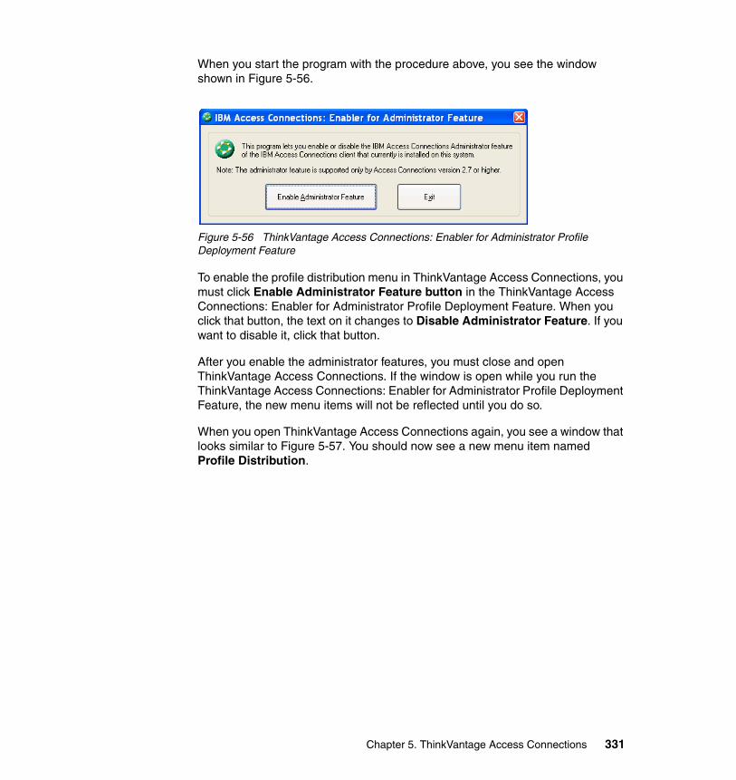
When you start the program with the procedure above, you see the window shown in Figure 5-56.
Figure 5-56 ThinkVantage Access Connections: Enabler for Administrator Profile Deployment Feature
To enable the profile distribution menu in ThinkVantage Access Connections, you must click Enable Administrator Feature button in the ThinkVantage Access Connections: Enabler for Administrator Profile Deployment Feature. When you click that button, the text on it changes to Disable Administrator Feature. If you want to disable it, click that button.
After you enable the administrator features, you must close and open ThinkVantage Access Connections. If the window is open while you run the ThinkVantage Access Connections: Enabler for Administrator Profile Deployment Feature, the new menu items will not be reflected until you do so.
When you open ThinkVantage Access Connections again, you see a window that looks similar to Figure 5-57. You should now see a new menu item named Profile Distribution.
Chapter 5. ThinkVantage Access Connections 331
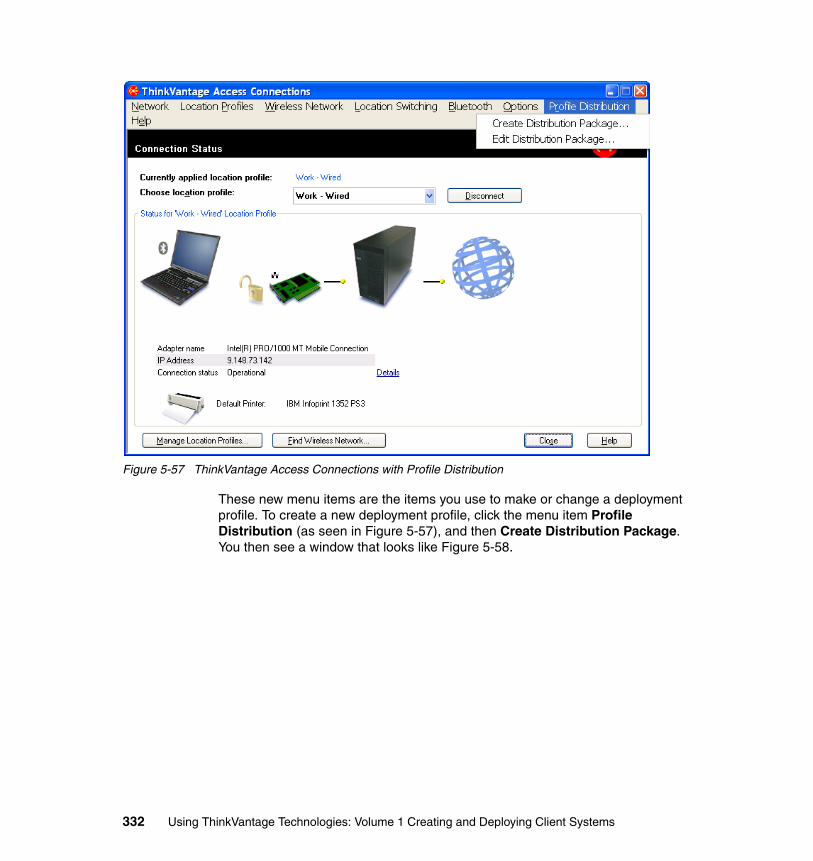
Figure 5-57 ThinkVantage Access Connections with Profile Distribution
These new menu items are the items you use to make or change a deployment profile. To create a new deployment profile, click the menu item Profile Distribution (as seen in Figure 5-57), and then Create Distribution Package. You then see a window that looks like Figure 5-58.
332 Using ThinkVantage Technologies: Volume 1 Creating and Deploying Client Systems
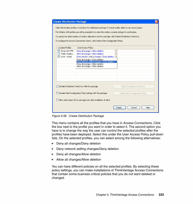
Figure 5-58 Create Distribution Package
This menu contains all the profiles that you have in Access Connections. Click the box next to the profile you want in order to select it. The second option you have is to change the way the user can control the selected profiles after the profiles have been deployed. Select this under the User Access Policy pull-down lists. On the selected profiles, you can select among the following alternatives:
� Deny all changes/Deny deletion
� Deny network setting changes/Deny deletion
� Deny all changes/Allow deletion
� Allow all changes/Allow deletion
You can have different policies on all the selected profiles. By selecting these policy settings, you can make installations of ThinkVantage Access Connections that contain some business critical policies that you do not want deleted or changed.
Chapter 5. ThinkVantage Access Connections 333
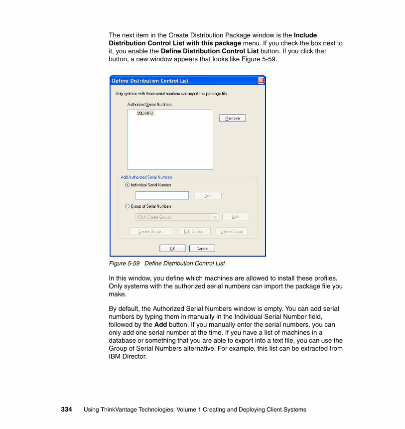
The next item in the Create Distribution Package window is the Include Distribution Control List with this package menu. If you check the box next to it, you enable the Define Distribution Control List button. If you click that button, a new window appears that looks like Figure 5-59.
Figure 5-59 Define Distribution Control List
In this window, you define which machines are allowed to install these profiles. Only systems with the authorized serial numbers can import the package file you make.
By default, the Authorized Serial Numbers window is empty. You can add serial numbers by typing them in manually in the Individual Serial Number field, followed by the Add button. If you manually enter the serial numbers, you can only add one serial number at the time. If you have a list of machines in a database or something that you are able to export into a text file, you can use the Group of Serial Numbers alternative. For example, this list can be extracted from IBM Director.
334 Using ThinkVantage Technologies: Volume 1 Creating and Deploying Client Systems
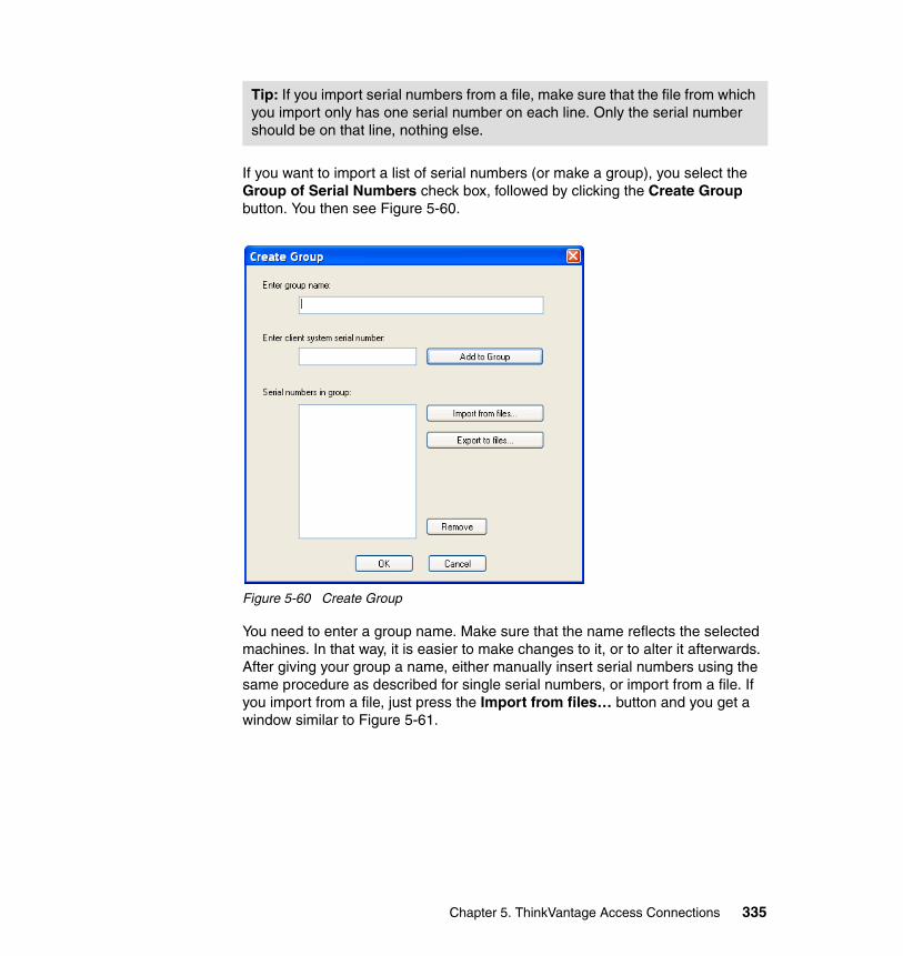
If you want to import a list of serial numbers (or make a group), you select the Group of Serial Numbers check box, followed by clicking the Create Group button. You then see Figure 5-60.
Figure 5-60 Create Group
You need to enter a group name. Make sure that the name reflects the selected machines. In that way, it is easier to make changes to it, or to alter it afterwards. After giving your group a name, either manually insert serial numbers using the same procedure as described for single serial numbers, or import from a file. If you import from a file, just press the Import from files… button and you get a window similar to Figure 5-61.
Tip: If you import serial numbers from a file, make sure that the file from which you import only has one serial number on each line. Only the serial number should be on that line, nothing else.
Chapter 5. ThinkVantage Access Connections 335
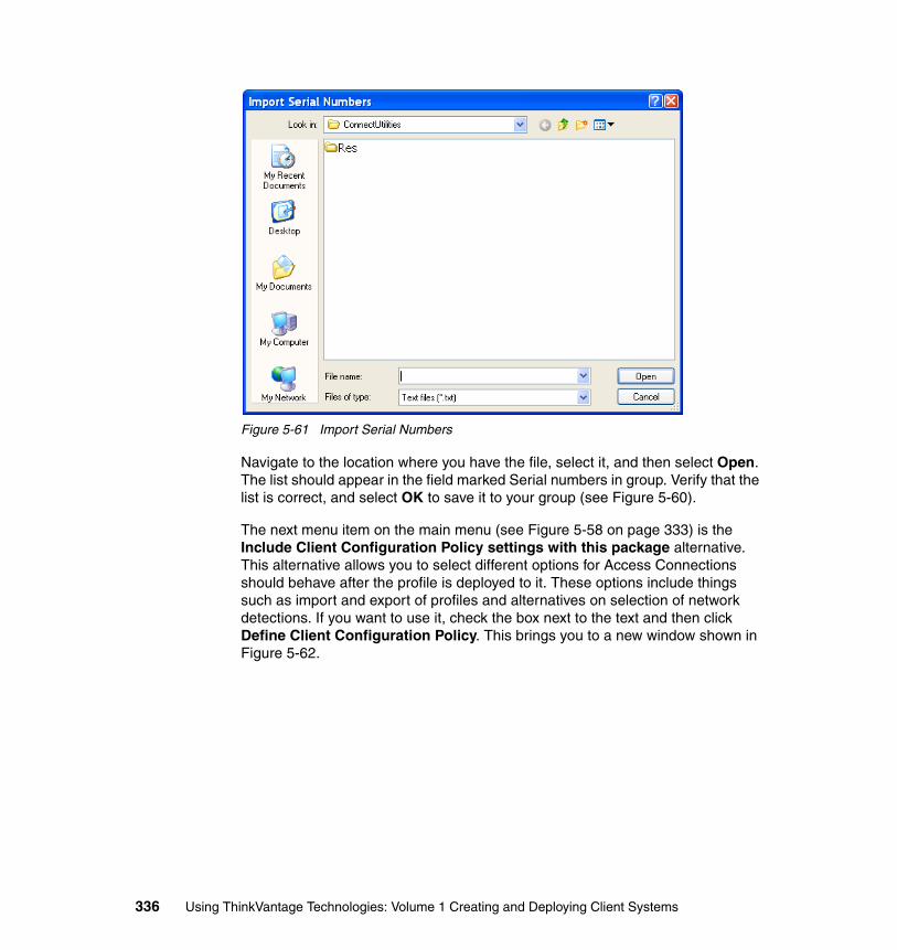
Figure 5-61 Import Serial Numbers
Navigate to the location where you have the file, select it, and then select Open. The list should appear in the field marked Serial numbers in group. Verify that the list is correct, and select OK to save it to your group (see Figure 5-60).
The next menu item on the main menu (see Figure 5-58 on page 333) is the Include Client Configuration Policy settings with this package alternative. This alternative allows you to select different options for Access Connections should behave after the profile is deployed to it. These options include things such as import and export of profiles and alternatives on selection of network detections. If you want to use it, check the box next to the text and then click Define Client Configuration Policy. This brings you to a new window shown in Figure 5-62.
336 Using ThinkVantage Technologies: Volume 1 Creating and Deploying Client Systems
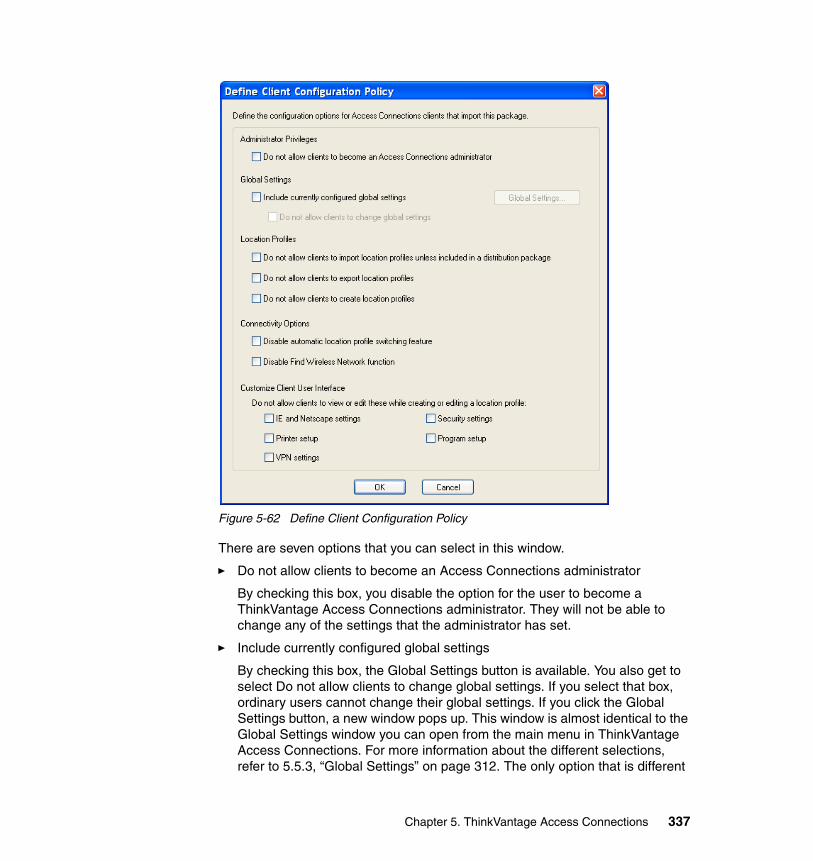
Figure 5-62 Define Client Configuration Policy
There are seven options that you can select in this window.
� Do not allow clients to become an Access Connections administrator
By checking this box, you disable the option for the user to become a ThinkVantage Access Connections administrator. They will not be able to change any of the settings that the administrator has set.
� Include currently configured global settings
By checking this box, the Global Settings button is available. You also get to select Do not allow clients to change global settings. If you select that box, ordinary users cannot change their global settings. If you click the Global Settings button, a new window pops up. This window is almost identical to the Global Settings window you can open from the main menu in ThinkVantage Access Connections. For more information about the different selections, refer to 5.5.3, “Global Settings” on page 312. The only option that is different
Chapter 5. ThinkVantage Access Connections 337
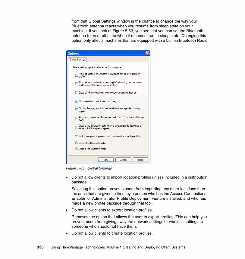
from that Global Settings window is the chance to change the way your Bluetooth antenna reacts when you resume from sleep state on your machine. If you look at Figure 5-63, you see that you can set the Bluetooth antenna to on or off state when it resumes from a sleep state. Changing this option only affects machines that are equipped with a built-in Bluetooth Radio.
Figure 5-63 Global Settings
� Do not allow clients to import location profiles unless included in a distribution package.
Selecting this option prevents users from importing any other locations than the ones that are given to them by a person who has the Access Connections: Enabler for Administrator Profile Deployment Feature installed, and who has made a new profile package through that tool.
� Do not allow clients to export location profiles.
Removes the option that allows the user to export profiles. This can help you prevent users from giving away the network settings or wireless settings to someone who should not have them.
� Do not allow clients to create location profiles.
338 Using ThinkVantage Technologies: Volume 1 Creating and Deploying Client Systems
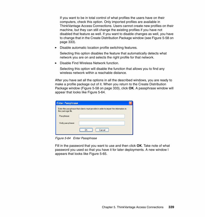
If you want to be in total control of what profiles the users have on their computers, check this option. Only imported profiles are available in ThinkVantage Access Connections. Users cannot create new profiles on their machine, but they can still change the existing profiles if you have not disabled that feature as well. If you want to disable changes as well, you have to change that in the Create Distribution Package window (see Figure 5-58 on page 333).
� Disable automatic location profile switching features.
Selecting this option disables the feature that automatically detects what network you are on and selects the right profile for that network.
� Disable Find Wireless Network function.
Selecting this option will disable the function that allows you to find any wireless network within a reachable distance.
After you have set all the options in all the described windows, you are ready to make a profile package out of it. When you return to the Create Distribution Package window (Figure 5-58 on page 333), click OK. A passphrase window will appear that looks like Figure 5-64.
Figure 5-64 Enter Passphrase
Fill in the password that you want to use and then click OK. Take note of what password you used so that you have it for later deployments. A new window l appears that looks like Figure 5-65.
Chapter 5. ThinkVantage Access Connections 339
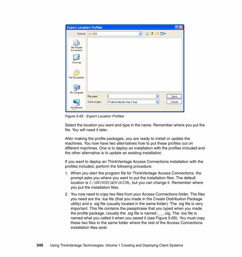
Figure 5-65 Export Location Profiles
Select the location you want and type in the name. Remember where you put the file. You will need it later.
After making the profile packages, you are ready to install or update the machines. You now have two alternatives how to put these profiles out on different machines. One is to deploy an installation with the profiles included and the other alternative is to update an existing installation.
If you want to deploy an ThinkVantage Access Connections installation with the profiles included, perform the following procedure:
1. When you start the program file for ThinkVantage Access Connections, the prompt asks you where you want to put the installation files. The default location is C:\DRIVERS\W2K\ACCON, but you can change it. Remember where you put the installation files.
2. You now need to copy two files from your Access Connections folder. The files you need are the .loa file (that you made in the Create Distribution Package utility) and a .sig file (usually located in the same folder). The .sig file is very important. This file contains the passphrase that you typed when you made the profile package. Usually the .sig file is named ___.sig. The .loa file is named what you called it when you saved it (see Figure 5-65). You must copy these two files to the same folder where the rest of the Access Connections installation files exist.
340 Using ThinkVantage Technologies: Volume 1 Creating and Deploying Client Systems
3. When all the files are collected, you can either start a manual installation by starting the setup.exe, or you can have an unattended setup by using:
setup -s -sms
We describe this in 5.3.2, “Automated installation” on page 280 and in 5.3.3, “Manual installation” on page 280.
If you want to deploy new or changed profiles after you install ThinkVantage Access Connections on a machine, use the following procedure:
1. Make a new profile package. It is very important that you use the same password that you used the first time. This ensures that the profile is loaded.
2. Create a script that copies the new .loa file and the .sig file to the location where ThinkVantage Access Connections is installed (or you can do it manually). The default location is:
C:\Program Files\ThinkPad\ConnectUtilities
but you may have changed it.
3. When you have copied the files to that location, close ThinkVantage Access Connections completely (or reboot).
4. Start ThinkVantage Access Connections again and it should include your new profiles or settings.
Making profiles in ThinkVantage Access Connections is quite easy. The thing you have to remember is the location of the different files. The .loa file and the .sig file are the two most important files in this process.
5.7 TroubleshootingThis topic is covered in the Access Connections Help file. You access the Help file by using the Help menu item located at the bottom of the ThinkVantage Access Connections application window, or manually open the Help file. The name of the Help file is QCONNECT.CHM and the location is in the installation directory.
5.8 Reference material� You can download this application from the following Web site:
http://www.ibm.com/pc/support/site.wss/migr-4zlnjb.html
� After you install the application, the Help file QCONNECT.CHM is located in the installation directory.
Chapter 5. ThinkVantage Access Connections 341
� ThinkVantage Access Connections: Enabler for Administrator Profile Deployment Feature:
http://www.ibm.com/pc/support/site.wss/document.do?lndocid=MIGR-52881
342 Using ThinkVantage Technologies: Volume 1 Creating and Deploying Client Systems
Chapter 6. Active Protection System
This chapter covers the Active Protection System (APS) that is available on many new ThinkPad models.
The Active Protection System features an integrated motion sensor (accelerometer) that continuously monitors movement of the ThinkPad notebook. Like an airbag’s sensor, it can detect sudden changes in motion and temporarily stop the hard drive to protect it from some crashes due to everyday notebook accidents. It provides up to four times greater impact protection than systems without this feature. This can be of great benefit especially in highly mobile systems which are at continual risk of being dropped and damaged.
6
© Copyright IBM Corp. 2005. All rights reserved. 343
6.1 Active Protection System overviewThe ThinkVantage Active Protection System protects your hard disk drive when the shock sensor inside your ThinkPad computer detects a situation that could potentially cause damage to your hard disk drive. Damage to the hard disk drive generally results from physical shock to the hard disk drive.
One type of physical shock, called operating shock, occurs when the disk is in operation. During operation, the drive head is typically over the drive platters reading and writing data. When a physical shock to the drive occurs during operation, the head and the platters can come into contact causing both components to be damaged.
The second type of shock, called non-operating shock, occurs when the head is in the unloaded position, or not positioned over the platters. When a physical shock occurs in the non-operating state, the head can contact the ramp when it is positioned over it and damage the ability of the head to read and write data to the hard disk drive. That is where Lenovo’s Active Protection System comes into play. The following information describes the design and implementation of this technology.
With Windows XP or Windows 2000, the Active Protection System can protect the following hard disk drives:
� Primary hard disk drive
� Secondary hard disk drive installed in the Ultrabay Slim in the computer
� Secondary hard disk drive installed in the Ultrabay Slim of the X4 UltraBase Dock if attached to the computer
� Secondary hard disk drive installed in the Ultrabay Enhanced in the computer
Active Protection System cannot protect the following hard disk drives:
� Secondary hard disk drive connected to a USB connector
� Secondary hard disk drive installed in the PC Card slot
� Secondary hard disk drive installed in the Ultrabay 2000 of the ThinkPad Dock II
6.2 Supported ThinkPad modelsAt the time this redbook was written, the following ThinkPad models included the Active Protection System hardware feature:
� ThinkPad R50, R50p, R51, and R52
344 Using ThinkVantage Technologies: Volume 1 Creating and Deploying Client Systems
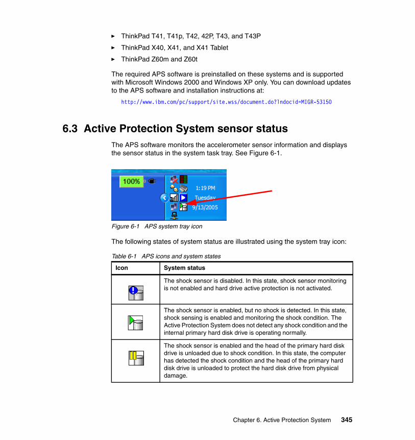
� ThinkPad T41, T41p, T42, 42P, T43, and T43P
� ThinkPad X40, X41, and X41 Tablet
� ThinkPad Z60m and Z60t
The required APS software is preinstalled on these systems and is supported with Microsoft Windows 2000 and Windows XP only. You can download updates to the APS software and installation instructions at:
http://www.ibm.com/pc/support/site.wss/document.do?lndocid=MIGR-53150
6.3 Active Protection System sensor statusThe APS software monitors the accelerometer sensor information and displays the sensor status in the system task tray. See Figure 6-1.
Figure 6-1 APS system tray icon
The following states of system status are illustrated using the system tray icon:
Table 6-1 APS icons and system states
Icon System status
The shock sensor is disabled. In this state, shock sensor monitoring is not enabled and hard drive active protection is not activated.
The shock sensor is enabled, but no shock is detected. In this state, shock sensing is enabled and monitoring the shock condition. The Active Protection System does not detect any shock condition and the internal primary hard disk drive is operating normally.
The shock sensor is enabled and the head of the primary hard disk drive is unloaded due to shock condition. In this state, the computer has detected the shock condition and the head of the primary hard disk drive is unloaded to protect the hard disk drive from physical damage.
Chapter 6. Active Protection System 345
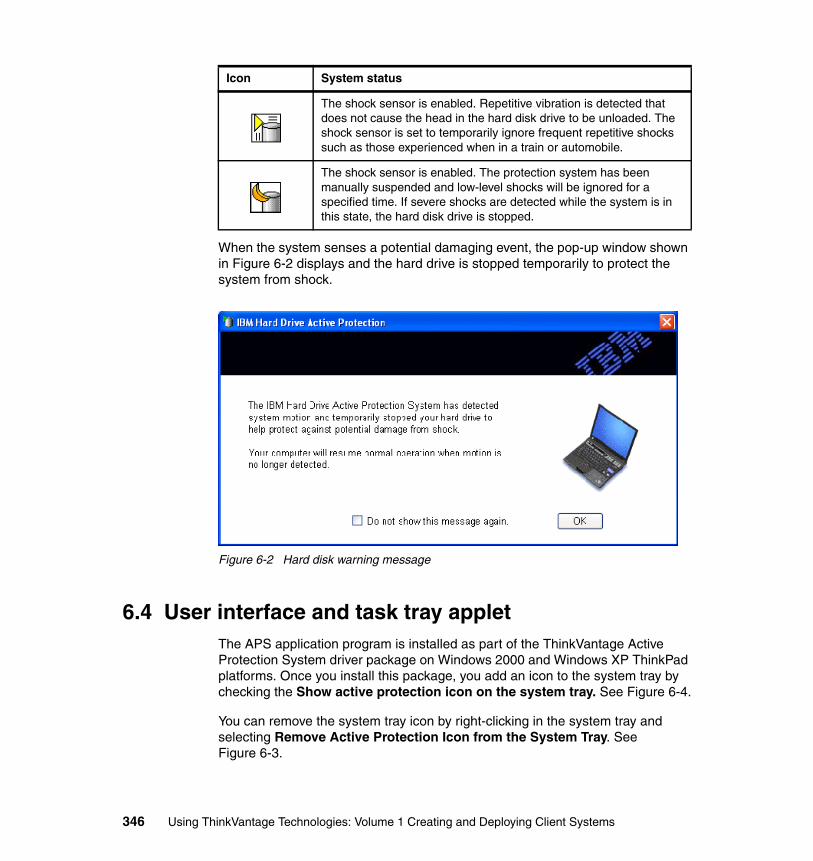
When the system senses a potential damaging event, the pop-up window shown in Figure 6-2 displays and the hard drive is stopped temporarily to protect the system from shock.
Figure 6-2 Hard disk warning message
6.4 User interface and task tray applet The APS application program is installed as part of the ThinkVantage Active Protection System driver package on Windows 2000 and Windows XP ThinkPad platforms. Once you install this package, you add an icon to the system tray by checking the Show active protection icon on the system tray. See Figure 6-4.
You can remove the system tray icon by right-clicking in the system tray and selecting Remove Active Protection Icon from the System Tray. See Figure 6-3.
The shock sensor is enabled. Repetitive vibration is detected that does not cause the head in the hard disk drive to be unloaded. The shock sensor is set to temporarily ignore frequent repetitive shocks such as those experienced when in a train or automobile.
The shock sensor is enabled. The protection system has been manually suspended and low-level shocks will be ignored for a specified time. If severe shocks are detected while the system is in this state, the hard disk drive is stopped.
Icon System status
346 Using ThinkVantage Technologies: Volume 1 Creating and Deploying Client Systems
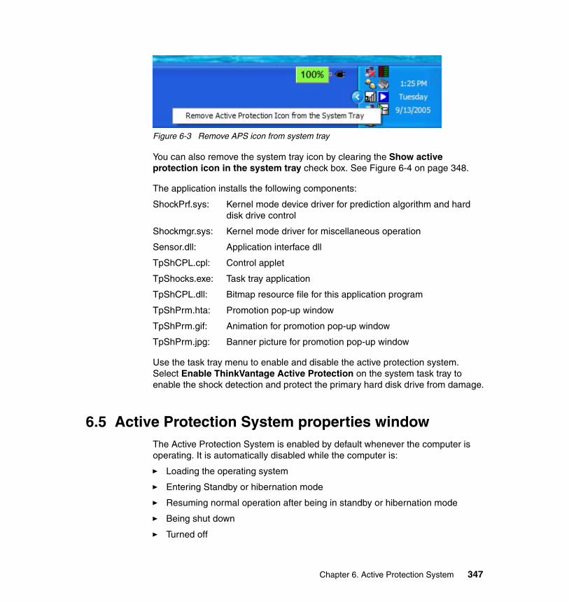
Figure 6-3 Remove APS icon from system tray
You can also remove the system tray icon by clearing the Show active protection icon in the system tray check box. See Figure 6-4 on page 348.
The application installs the following components:
ShockPrf.sys: Kernel mode device driver for prediction algorithm and hard disk drive control
Shockmgr.sys: Kernel mode driver for miscellaneous operation
Sensor.dll: Application interface dll
TpShCPL.cpl: Control applet
TpShocks.exe: Task tray application
TpShCPL.dll: Bitmap resource file for this application program
TpShPrm.hta: Promotion pop-up window
TpShPrm.gif: Animation for promotion pop-up window
TpShPrm.jpg: Banner picture for promotion pop-up window
Use the task tray menu to enable and disable the active protection system. Select Enable ThinkVantage Active Protection on the system task tray to enable the shock detection and protect the primary hard disk drive from damage.
6.5 Active Protection System properties windowThe Active Protection System is enabled by default whenever the computer is operating. It is automatically disabled while the computer is:
� Loading the operating system
� Entering Standby or hibernation mode
� Resuming normal operation after being in standby or hibernation mode
� Being shut down
� Turned off
Chapter 6. Active Protection System 347
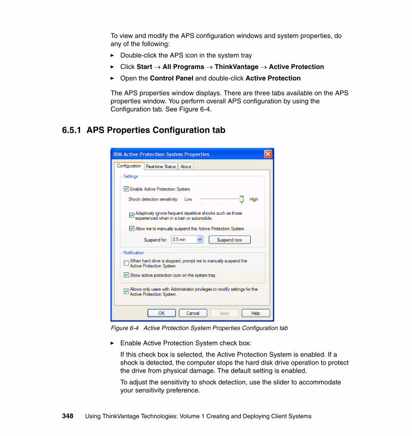
To view and modify the APS configuration windows and system properties, do any of the following:
� Double-click the APS icon in the system tray
� Click Start → All Programs → ThinkVantage → Active Protection
� Open the Control Panel and double-click Active Protection
The APS properties window displays. There are three tabs available on the APS properties window. You perform overall APS configuration by using the Configuration tab. See Figure 6-4.
6.5.1 APS Properties Configuration tab
Figure 6-4 Active Protection System Properties Configuration tab
� Enable Active Protection System check box:
If this check box is selected, the Active Protection System is enabled. If a shock is detected, the computer stops the hard disk drive operation to protect the drive from physical damage. The default setting is enabled.
To adjust the sensitivity to shock detection, use the slider to accommodate your sensitivity preference.
348 Using ThinkVantage Technologies: Volume 1 Creating and Deploying Client Systems
� Adaptively ignore frequent repetitive shocks check box:
Select this option to avoid frequent stops of the hard drive when you use the computer in an environment where the shock sensor is likely to detect repetitive, low-level shocks, such as those experienced when riding on a train or airplane. If enabled, this option functions when the number of hard disk drive stops caused by the protection system responding to low-level shocks exceeds a specific number within a certain amount of time (stop threshold). After the stop threshold is exceeded and the shock sensor detects a stable environment, the protection system will begin to temporarily ignore the low-level shocks. Once the shock sensor detects a stable environment for an extended amount of time, this option will be reset so that the stop threshold must again be exceeded in order for the protection system to begin ignoring low-level shocks. When it is enabled, the protection system will always stop the hard disk drive when heavy shocks are detected.
� Allow me to manually suspend Active Protection System check box:
If this check box is selected, you can make the protection system stop its operation temporarily for a specified length of time. During that length of time, the protection system ignores low-level shocks. If severe shocks are detected while the system is in this state, the hard disk drive is stopped. Select your preferred suspend time from the pull-down box.
� When hard drive is stopped check box, prompt me to manually suspend the Active Protection System:
Select this check box if you want to see a pop-up message for manually suspending the protection system when low-level shocks or repetitive vibrations are detected. The pop-up message will display above the Active Protection System icon on the system tray.
� Show active protection icon on the system tray check box:
If the check box is selected, the icon showing the status of the shock sensor displays in the system tray.
� Allow only users with Administrator privileges to modify settings for the Active Protection System check box:
If this check box is selected, you must have Administrator privileges to configure the following settings:
– Check box for enabling the Active Protection System
– Check box for temporarily ignoring repetitive, low-level shocks
– Check box for suspending the Active Protection System for a specified length of time
– Check box for configuring the privileged settings of the Active Protection System
Chapter 6. Active Protection System 349
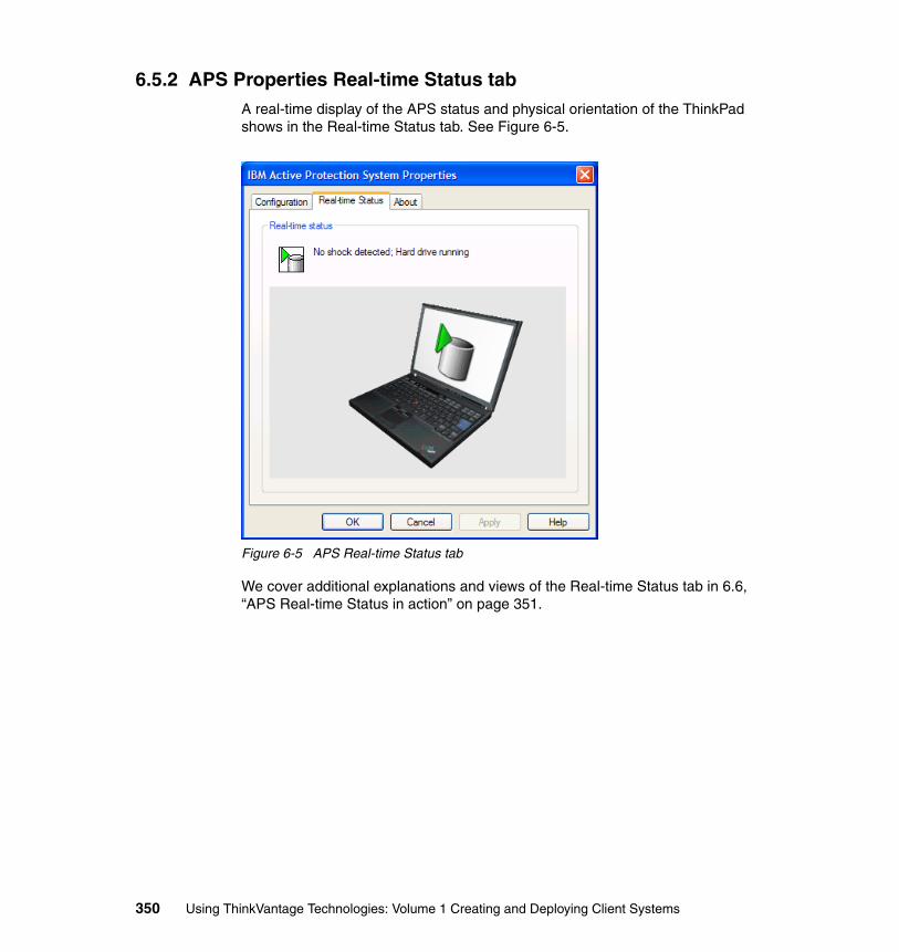
6.5.2 APS Properties Real-time Status tabA real-time display of the APS status and physical orientation of the ThinkPad shows in the Real-time Status tab. See Figure 6-5.
Figure 6-5 APS Real-time Status tab
We cover additional explanations and views of the Real-time Status tab in 6.6, “APS Real-time Status in action” on page 351.
350 Using ThinkVantage Technologies: Volume 1 Creating and Deploying Client Systems
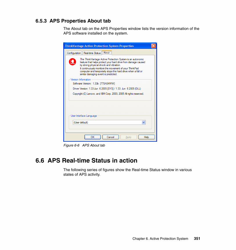
6.5.3 APS Properties About tabThe About tab on the APS Properties window lists the version information of the APS software installed on the system.
Figure 6-6 APS About tab
6.6 APS Real-time Status in actionThe following series of figures show the Real-time Status window in various states of APS activity.
Chapter 6. Active Protection System 351
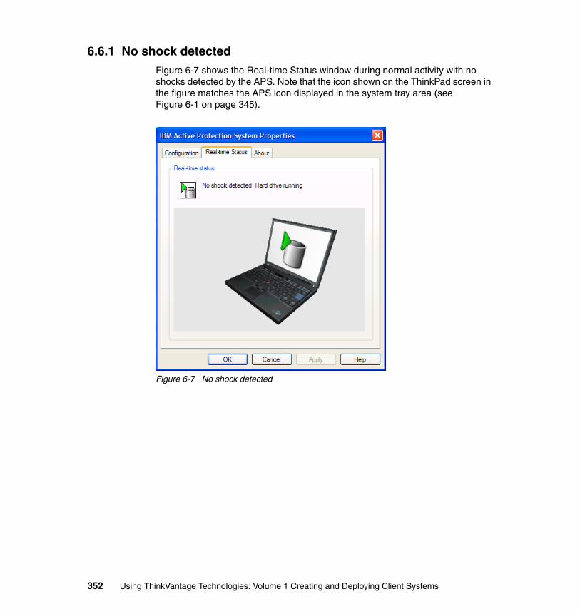
6.6.1 No shock detectedFigure 6-7 shows the Real-time Status window during normal activity with no shocks detected by the APS. Note that the icon shown on the ThinkPad screen in the figure matches the APS icon displayed in the system tray area (see Figure 6-1 on page 345).
Figure 6-7 No shock detected
352 Using ThinkVantage Technologies: Volume 1 Creating and Deploying Client Systems
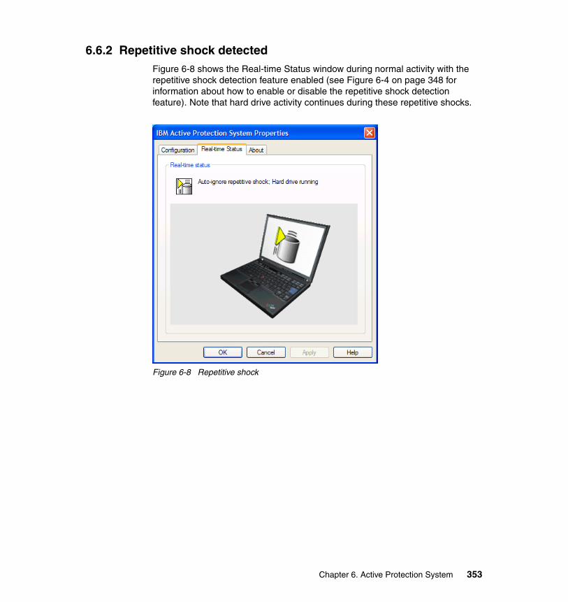
6.6.2 Repetitive shock detectedFigure 6-8 shows the Real-time Status window during normal activity with the repetitive shock detection feature enabled (see Figure 6-4 on page 348 for information about how to enable or disable the repetitive shock detection feature). Note that hard drive activity continues during these repetitive shocks.
Figure 6-8 Repetitive shock
Chapter 6. Active Protection System 353
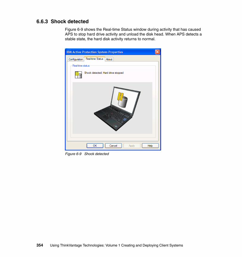
6.6.3 Shock detectedFigure 6-9 shows the Real-time Status window during activity that has caused APS to stop hard drive activity and unload the disk head. When APS detects a stable state, the hard disk activity returns to normal.
Figure 6-9 Shock detected
354 Using ThinkVantage Technologies: Volume 1 Creating and Deploying Client Systems
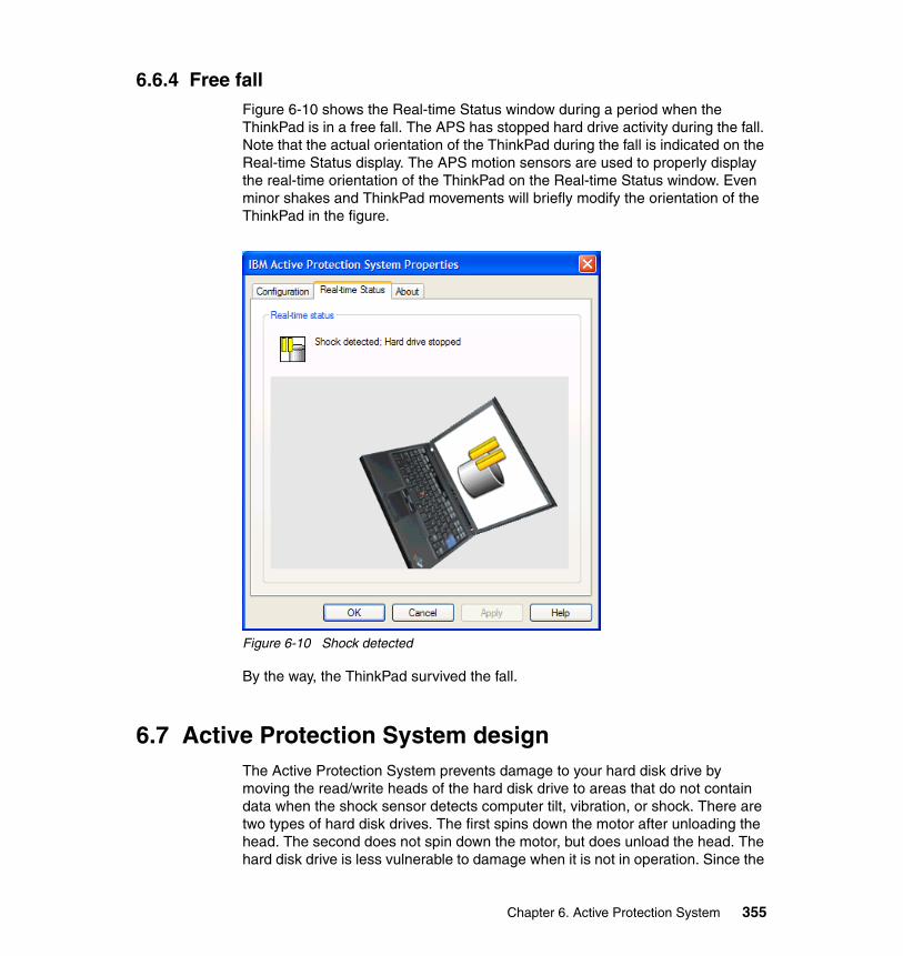
6.6.4 Free fallFigure 6-10 shows the Real-time Status window during a period when the ThinkPad is in a free fall. The APS has stopped hard drive activity during the fall. Note that the actual orientation of the ThinkPad during the fall is indicated on the Real-time Status display. The APS motion sensors are used to properly display the real-time orientation of the ThinkPad on the Real-time Status window. Even minor shakes and ThinkPad movements will briefly modify the orientation of the ThinkPad in the figure.
Figure 6-10 Shock detected
By the way, the ThinkPad survived the fall.
6.7 Active Protection System designThe Active Protection System prevents damage to your hard disk drive by moving the read/write heads of the hard disk drive to areas that do not contain data when the shock sensor detects computer tilt, vibration, or shock. There are two types of hard disk drives. The first spins down the motor after unloading the head. The second does not spin down the motor, but does unload the head. The hard disk drive is less vulnerable to damage when it is not in operation. Since the
Chapter 6. Active Protection System 355
hard disk drive cannot be accessed while the head is unloaded, it may seem to the user that the drive has stopped. In reality, the disk access request has been temporarily suspended at the disk driver position so that the disk head can remain unloaded until a stable situation is detected. The suspended disk access request is then released and passed to the disk and the hard disk drive to normal operation.
The Active Protection System uses a combination of hardware and software components. The hardware component is a motion sensor, or accelerometer, embedded in the motherboard which continually senses system orientation and movement. The software component receives and interprets signals from the accelerometer, differentiates between potentially harmful movements and repetitive motion, and signals the hard drive to stop when a potentially damaging event is predicted. The software component also includes a system tray icon and properties window.
6.7.1 Head unloading for increased hard disk drive shock tolerance As a result of extensive testing with the computer lid both open and closed, Lenovo has found that in typical drop accidents either from the knee or a desk to a concrete floor, the internal hard disk drive is protected by the durable ThinkPad shell so that the received shock level to the hard disk drive does not exceed 800G or 800 times the force of gravity. Since 800G is the maximum rating of shock tolerance of the hard disk drive with the head unloaded, the hard disk drive can be rescued from most accidents in typical usage if the disk head is unloaded prior to receiving the shock impact. Head unloading can take 300 to 500 ms, and the average duration after detecting a free-fall situation is 300 ms. Therefore, it is too late to start head unloading after detecting the free-fall situation. This makes it necessary to concentrate on the behavior of the machine prior to a drop. The initial behavior acts as a prediction of the impending accident. In general, the duration of the predicting event is much longer than the actual free-fall. This enables the Active Protection System to respond to the impending accident prior to receiving the shock. The machine posture or system orientation is constantly checked by monitoring acceleration and using a prediction algorithm to statistically analyze recent behavior in typical usage. Head unloading is initiated by degrees of tilt, acceleration, or shock. The degrees at which head unloading occurs are adjusted and fine-tuned every time a proper prediction is applied for the current motion. The disk drive head remains unloaded until detecting a stable environment for approximately one to four seconds depending upon the amount of excessive acceleration at the beginning of the current shock or posture change. The Real-time Status window in the Active Protection System Properties (see Figure 6-7 on page 352 through Figure 6-10 on page 355) will give you a live view of the computer’s physical movements.
356 Using ThinkVantage Technologies: Volume 1 Creating and Deploying Client Systems
6.7.2 Use of prediction algorithm The Active Protection System employs a heuristic learning algorithm to track system orientation. The Shock Manager, a system thread created by the Shockprf.sys of a kernel mode device driver, analyzes the variations in acceleration and collects system orientation data into the Shock History Database. The collected data is then used to tune sensitivity and predict excessive shocks. This tuning is important in minimizing the disk performance penalty caused by prediction failures. Once the Shock Manager detects a certain variation which may be equivalent to one usually seen just before receiving an excessive shock, the Shock Manager stops the hard disk drive immediately.
The sensitivity to predict a shock varies depending on usage conditions. In general, the more stable the ThinkPad computer stays, the more sensitively the Shock Manager behaves. The Shock Manager focuses its attention on the current acceleration variation and the weighted average in the recent past. The log is used to minimize intrusive operation during normal usage of the computer. If the hard disk drive head is unloaded after detecting a potentially harmful situation, the user can shorten the current head-unloading period up to 1 second on the condition that a calm state, stable enough to remove the risk of a drop, continues for at least one second and at the same time mouse movement activity for more than 200 ms is detected, thereby informing the Active Protection System that this is not a drop situation.
The design of the Active Protection System allows for certain shocks or vibrations that fall within a span of accepted or normal motion and does not repeatedly stop the hard drive when this level of motion is detected. You can select a check box in the properties window to temporarily disable hard drive protection while repetitive motion or vibration is detected. This feature is particularly useful when the ThinkPad computer is used on a plane or train and repetitive vibration is expected.
6.8 SummaryThe ThinkVantage Active Protection System can greatly improve overall system reliability by providing hard drive protection from shock. Using the latest technology to constantly monitor the movement of your ThinkPad computer, you can feel confident that your data will be protected in the event of a drop or similar potentially damaging event.
The Active Protection System is enabled by default whenever the computer is operating. It is automatically disabled while the computer is:
� Loading the operating system
Chapter 6. Active Protection System 357
� Entering Standby or hibernation mode
� Resuming normal operation after being in standby or hibernation mode
� Being shut down
� Turned off
6.8.1 Summary of features� Enable/Disable feature
You can manually enable and disable the Active Protection System using the software user interface.
� Automatic ignore feature
Sometimes you are in an environment that has associated vibration (such as in a car or airplane where the entire vehicle vibrates). In these environments, the vibration may be transmitted to the ThinkPad computer. The Automatic Ignore feature is helpful in this situation. This feature is enabled by default, but you can manually change your choice at any time via the software utility.
� Cancel feature for impulse-type vibration
You cannot manually control this feature. The Shock Manager ignores impulse-type acceleration change in order to minimize prediction failures. An adaptive low-pass filter function inside the Shock Manager performs this function.
� Heuristic sensitivity tuning feature
You cannot manually control this feature. The sensitivity for shock prediction is dynamically changed depending on body posture change with received shocks, vibrations, and user input activities.
� Administrative lock
This feature restricts users without Administrative system rights from changing the Active Protection System properties.
358 Using ThinkVantage Technologies: Volume 1 Creating and Deploying Client Systems

Chapter 7. Implementing ThinkVantage Technologies
The ThinkVantage Technologies create a competitive advantage that can help your organization succeed. Addressing the PC life cycle, your workstations can become less dependent on IT staff or user intervention for basic tasks such as deployment, backup, security, and more, thereby freeing resources which you can refocus on driving business success.
The tools we discuss in this redbook are key contributors in deployment optimization. ThinkVantage Technologies allow PCs to be more than just “clients”.
7
© Copyright IBM Corp. 2005. All rights reserved. 359
7.1 Implementation planningWhen delivering a solution to your organization, it is very important to plan every aspect of a technology project. Quite often, implementations are successful because more time was spent planning than implementing. This can include long term plans to ensure your environment is manageable.
Successful planning requires a clear knowledge of the environment as well as clearly defined targets. When delivering a solution that involves the PC life cycle, you must include the entire process. Many organizations spend significant amounts on initial deployment without considering the costs. For example, after a machine has been deployed:
� What is the cost of getting that machine working again if the operating system fails? How will you reload the machine?
� How will you migrate user data?
� How will you implement image updates and changes?
� How will you dispose of the workstation when it is no longer useful?
There are numerous things to keep in mind when developing a long term solution for your organization. Using ThinkVantage Technologies will offer maximum value when implemented with a strong long term plan and objective.
The following sections will help you consider important elements before you complete your plan.
Organizational complexity and image managementHow many images are in your organization? Is this something your IT organization spends a lot of time managing? What is involved in keeping the current image environment?
Image management can quickly become a nightmare as complexity increases. Figure 7-1 on page 361 shows how implementing ImageUltra Builder with Ultra Portable images can benefit from DOE (Dynamic Operating Environment) and HIIT (Hardware Independent Imaging Technology). The representation is common to what you might see in a large bank environment.
360 Using ThinkVantage Technologies: Volume 1 Creating and Deploying Client Systems
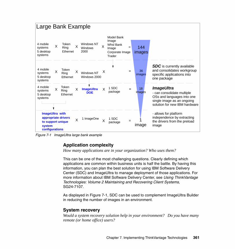
Figure 7-1 ImageUltra large bank example
Application complexityHow many applications are in your organization? Who uses them?
This can be one of the most challenging questions. Clearly defining which applications are common within business units is half the battle. By having this information, you can plan the best solution for using IBM Software Delivery Center (SDC) and ImageUltra to manage deployment of those applications. For more information about IBM Software Delivery Center, see Using ThinkVantage Technologies: Volume 2 Maintaining and Recovering Client Systems, SG24-7107.
As displayed in Figure 7-1, SDC can be used to complement ImageUltra Builder in reducing the number of images in an environment.
System recoveryWould a system recovery solution help in your environment? Do you have many remote (or home office) users?
4 mobile systems5 desktop systems
Token RingEthernet
WindowsNTWindows2000
1 SDCpackageX X X = 36
images
SDC is currently available and consolidates workgroup specific applications into one package
4 mobile systems5 desktop systems
Token RingEthernet
ImageUltra DOE
X X X = 18 images
1 ImageOneX X = 1 image
ImageUltra - can consolidate multiple OS's and languages into one singel image as an ongoing solution for new IBM hardware
- allows for platform independence by abstracting the drivers from the preload image
ImageUltra withappropriate driversto support unique system configurations
Large Bank Example
4 mobile systems5 desktop systems
Token RingEthernet
WindowsNTWindows2000
Model Bank ImageWhsl Bank ImageCorporate ImageTrader
X X X = 144 images
1 SDCpackage
1 SDCpackage
4 mobile systems5 desktop systems
Token RingEthernet
Windows NTWindows 2000
X X X = 36 images
SDC is currently available and consolidates workgroup specific applications into one package
4 mobile systems5 desktop systems
Token RingEthernet
ImageUltra DOE
X X X = 18 images
1 ImageOneX X = 1 image
ImageUltra - can consolidate multiple OSs and languages into one single image as an ongoing solution for new IBM hardware
- allows for platform independence by extracting the drivers from the preload image
ImageUltra withappropriate driversto support unique system configurations
Large Bank Example
4 mobile systems5 desktop systems
Token RingEthernet
Windows NTWindows 2000
Model Bank ImageWhsl Bank ImageCorporate ImageTrader
X X X = 144 images
1 SDCpackage
1 SDCpackage
Chapter 7. Implementing ThinkVantage Technologies 361
Using a tool like Rescue and Recovery can help ensure your users can recover from an image failure quickly without having to wait for a technician. Often, a user can be up and running in minutes.
How do I link Rescue and Recovery into ImageUltra Builder?
In this book, we discuss how to set up Rescue and Recovery so a user (or technician) can initiate the silent installation process (through ImageUltra Builder). This is particularly useful when you want to ensure the user's workstation is fully configured before running the installation process. This ensures the base backup on the machine is fully customized for that particular user.
Vendor and platform standardizationWhen an organization limits the vendors and platforms they purchase, they benefit from:
� Purchasing power: Leverage greater volume purchases if you are getting things from a smaller number of vendors.
� Simplification of compatibility: Your support organization will benefit from reduced testing times when determining compatibility of software, drivers, and so on.
� Vendor management: Less time required for managing your vendors since the number of vendors is smaller.
� Support: You may save money on any service contracts that need to be duplicated between vendors.
� Reduction of the amount of testing when integrating new hardware peripherals or software.
� Product knowledge: Training support staff on fewer hardware/software platforms makes it easier to provide consistent service.
A homogeneous environment is easier to maintain and will lower the cost of ownership. Standardization enhanced with the ThinkVantage Tools offers an unparalleled solution for managing your environment.
Removing existing imaging applicationsCan I get rid of my existing cloning program?
If you plan to use UltraPortable images only, you can get rid of external imaging tools. However, in mixed hardware environments, you will need to keep an imaging tool to deploy machines.
362 Using ThinkVantage Technologies: Volume 1 Creating and Deploying Client Systems
UltraPortable solutionWhy do I need an UltraPortable solution?
The UltraPortable solution provides the greatest flexibility for different hardware types. Portable Sysprep images can sometimes have problems installing on machines that have differences in core chipsets.
Handling migrationHow does SMA work in this process?
There are many ways you can integrate SMA into the process. In ImageUltra Builder, SMA can be run in batch mode to import a user’s profile. In addition, IBM Director can also be used to run the migration process as a task.
7.2 ThinkVantage TechnologiesThe following sections outline the various ThinkVantage Technologies components.
ImageUltra BuilderImageUltra Builder allows for the creation of one single SMART image that can be easily updated and deployed across an organization. This modularity allows for easy updates and simplified testing because the build processes for unchanged modules will always be consistent.
Some benefits you will see are as follows:
� Reduction in the number of images within an organization. This vastly reduces the efforts required to maintain “image libraries”.
� ImageUltra Builder allows for integration of existing images. You can load any existing images into the repository. This can be extremely helpful for legacy workstations in the environment.
� Ease of implementation. The modules are showcased in a console that allows for easy identification.
� Flexibility. By supporting existing imaging technologies, organizations can gradually transition to a SMART (that is, UltraPortable) image through the standard attrition process. Another alternative is to replace PCs using a “big bang” deployment. Customers have seen that cost reductions through platform standardization can greatly offset the initial costs of the hardware required for this process.
� IT organizations find the repeatable build process an excellent way to ensure the support organization gets the same standards across a company.
Chapter 7. Implementing ThinkVantage Technologies 363
� Administrators can easily determine what the ImageUltra Builder loads through the graphical interface. This can save time over traditional imaging technologies where each individual image must be located to determine its contents.
� Multiple deployment options are possible via Network or CD distribution to fit your business requirements.
System Migration AssistantDuring the procurement of a new PC, migration of data and settings is often the most time consuming part of the task. By automating the migration process through the use of SMA, settings and data are not overlooked.
Using SMA allows user data, Windows settings and “application personalities” to be transferred to a new machine. During the process, the user can also validate the data to be captured before it is downloaded to the new environment.
Some benefits users experience are as follows:
� Reduction in cost for migration to new clients
� Enabling the control of service level agreements through:
– Consistent migration results
– Reduction of Help center calls because of possible misconfigurations often associated with manual migrations
� Ability to perform migration tasks on their own using the SMA tool, relieving the burden on IT resources.
The following example allows migration to occur without the requirement for network/external storage. It also illustrates where SMA is implemented in the deployment process.
364 Using ThinkVantage Technologies: Volume 1 Creating and Deploying Client Systems
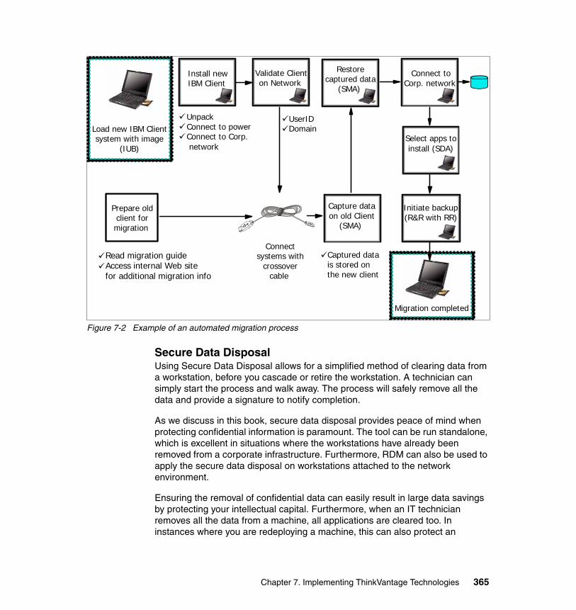
Figure 7-2 Example of an automated migration process
Secure Data Disposal Using Secure Data Disposal allows for a simplified method of clearing data from a workstation, before you cascade or retire the workstation. A technician can simply start the process and walk away. The process will safely remove all the data and provide a signature to notify completion.
As we discuss in this book, secure data disposal provides peace of mind when protecting confidential information is paramount. The tool can be run standalone, which is excellent in situations where the workstations have already been removed from a corporate infrastructure. Furthermore, RDM can also be used to apply the secure data disposal on workstations attached to the network environment.
Ensuring the removal of confidential data can easily result in large data savings by protecting your intellectual capital. Furthermore, when an IT technician removes all the data from a machine, all applications are cleared too. In instances where you are redeploying a machine, this can also protect an
Load new IBM Clientsystem with image
(IUB)
Prepare oldclient formigration
Read migration guideAccess internal Web sitefor additional migration info
UnpackConnect to powerConnect to Corp. network
UserIDDomain
Connectsystems with
crossovercable
Capture dataon old Client
(SMA)
Captured datais stored onthe new client
Connect toCorp. network
Migration completed
Restorecaptured data
(SMA)
Validate Clienton Network
Install newIBM Client
Initiate backup(R&R with RR)
Select apps toinstall (SDA)
Chapter 7. Implementing ThinkVantage Technologies 365

organization from software license exposures that may occur from loading the same applications on multiple workstations.
7.3 Migration/rollout scenariosIn this section, we show you different scenarios to demonstrate how ThinkVantage Tools can be used together.
7.3.1 PC migration or upgradeIn this section, we show you an example of how you can do a migration or an operating system upgrade by using the different ThinkVantage Tools.
For example, a user has a ThinkPad 600 with Windows 98. The user receives a ThinkPad T40 with Windows XP. Or another example, a company wants to use the ThinkVantage Tools to upgrade from Windows NT to Windows XP.
We briefly describe the process steps to follow for a migration. See the corresponding chapters in this book and Using ThinkVantage Technologies: Volume 2 Maintaining and Recovering Client Systems, SG24-7107, for detailed use and configuration of the ThinkVantage Tools.
366 Using ThinkVantage Technologies: Volume 1 Creating and Deploying Client Systems
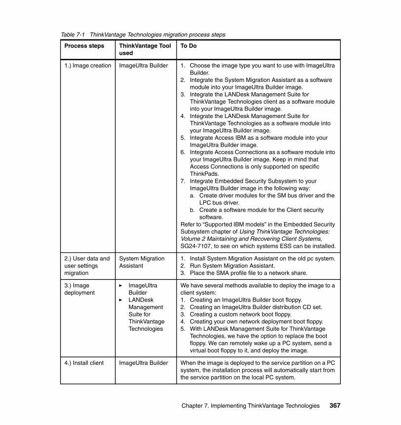
Table 7-1 ThinkVantage Technologies migration process steps
Process steps ThinkVantage Tool used
To Do
1.) Image creation ImageUltra Builder 1. Choose the image type you want to use with ImageUltra Builder.
2. Integrate the System Migration Assistant as a software module into your ImageUltra Builder image.
3. Integrate the LANDesk Management Suite for ThinkVantage Technologies client as a software module into your ImageUltra Builder image.
4. Integrate the LANDesk Management Suite for ThinkVantage Technologies as a software module into your ImageUltra Builder image.
5. Integrate Access IBM as a software module into your ImageUltra Builder image.
6. Integrate Access Connections as a software module into your ImageUltra Builder image. Keep in mind that Access Connections is only supported on specific ThinkPads.
7. Integrate Embedded Security Subsystem to your ImageUltra Builder image in the following way:a. Create driver modules for the SM bus driver and the
LPC bus driver.b. Create a software module for the Client security
software.Refer to “Supported IBM models” in the Embedded Security Subsystem chapter of Using ThinkVantage Technologies: Volume 2 Maintaining and Recovering Client Systems, SG24-7107, to see on which systems ESS can be installed.
2.) User data and user settings migration
System Migration Assistant
1. Install System Migration Assistant on the old pc system.2. Run System Migration Assistant.3. Place the SMA profile file to a network share.
3.) Image deployment
� ImageUltra Builder
� LANDesk Management Suite for ThinkVantage Technologies
We have several methods available to deploy the image to a client system: 1. Creating an ImageUltra Builder boot floppy.2. Creating an ImageUltra Builder distribution CD set.3. Creating a custom network boot floppy.4. Creating your own network deployment boot floppy.5. With LANDesk Management Suite for ThinkVantage
Technologies, we have the option to replace the boot floppy. We can remotely wake up a PC system, send a virtual boot floppy to it, and deploy the image.
4.) Install client ImageUltra Builder When the image is deployed to the service partition on a PC system, the installation process will automatically start from the service partition on the local PC system.
Chapter 7. Implementing ThinkVantage Technologies 367
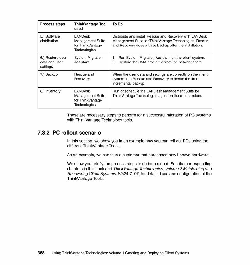
These are necessary steps to perform for a successful migration of PC systems with ThinkVantage Technology tools.
7.3.2 PC rollout scenarioIn this section, we show you in an example how you can roll out PCs using the different ThinkVantage Tools.
As an example, we can take a customer that purchased new Lenovo hardware.
We show you briefly the process steps to do for a rollout. See the corresponding chapters in this book and ThinkVantage Technologies: Volume 2 Maintaining and Recovering Client Systems, SG24-7107, for detailed use and configuration of the ThinkVantage Tools.
5.) Software distribution
LANDesk Management Suite for ThinkVantage Technologies
Distribute and install Rescue and Recovery with LANDesk Management Suite for ThinkVantage Technologies. Rescue and Recovery does a base backup after the installation.
6.) Restore user data and user settings
System Migration Assistant
1. Run System Migration Assistant on the client system.2. Restore the SMA profile file from the network share.
7.) Backup Rescue and Recovery
When the user data and settings are correctly on the client system, run Rescue and Recovery to create the first incremental backup.
8.) Inventory LANDesk Management Suite for ThinkVantage Technologies
Run or schedule the LANDesk Management Suite for ThinkVantage Technologies agent on the client system.
Process steps ThinkVantage Tool used
To Do
368 Using ThinkVantage Technologies: Volume 1 Creating and Deploying Client Systems
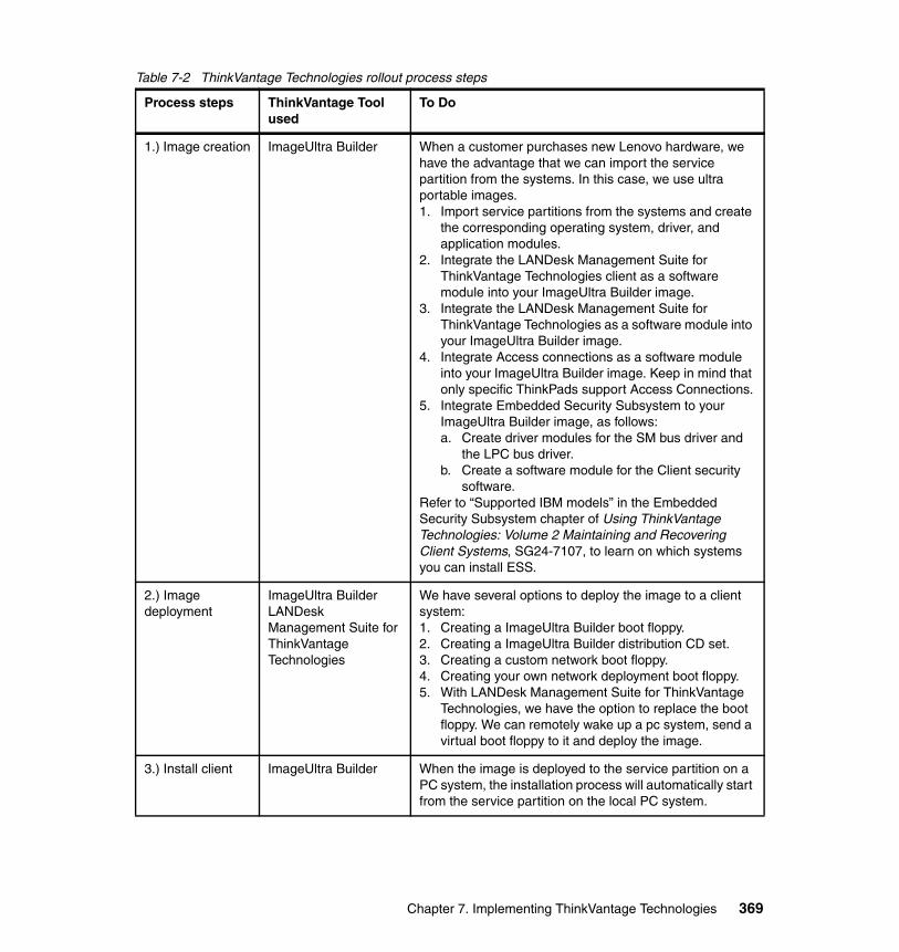
Table 7-2 ThinkVantage Technologies rollout process steps
Process steps ThinkVantage Tool used
To Do
1.) Image creation ImageUltra Builder When a customer purchases new Lenovo hardware, we have the advantage that we can import the service partition from the systems. In this case, we use ultra portable images.1. Import service partitions from the systems and create
the corresponding operating system, driver, and application modules.
2. Integrate the LANDesk Management Suite for ThinkVantage Technologies client as a software module into your ImageUltra Builder image.
3. Integrate the LANDesk Management Suite for ThinkVantage Technologies as a software module into your ImageUltra Builder image.
4. Integrate Access connections as a software module into your ImageUltra Builder image. Keep in mind that only specific ThinkPads support Access Connections.
5. Integrate Embedded Security Subsystem to your ImageUltra Builder image, as follows:a. Create driver modules for the SM bus driver and
the LPC bus driver.b. Create a software module for the Client security
software.Refer to “Supported IBM models” in the Embedded Security Subsystem chapter of Using ThinkVantage Technologies: Volume 2 Maintaining and Recovering Client Systems, SG24-7107, to learn on which systems you can install ESS.
2.) Image deployment
ImageUltra BuilderLANDesk Management Suite for ThinkVantage Technologies
We have several options to deploy the image to a client system: 1. Creating a ImageUltra Builder boot floppy.2. Creating a ImageUltra Builder distribution CD set.3. Creating a custom network boot floppy.4. Creating your own network deployment boot floppy.5. With LANDesk Management Suite for ThinkVantage
Technologies, we have the option to replace the boot floppy. We can remotely wake up a pc system, send a virtual boot floppy to it and deploy the image.
3.) Install client ImageUltra Builder When the image is deployed to the service partition on a PC system, the installation process will automatically start from the service partition on the local PC system.
Chapter 7. Implementing ThinkVantage Technologies 369
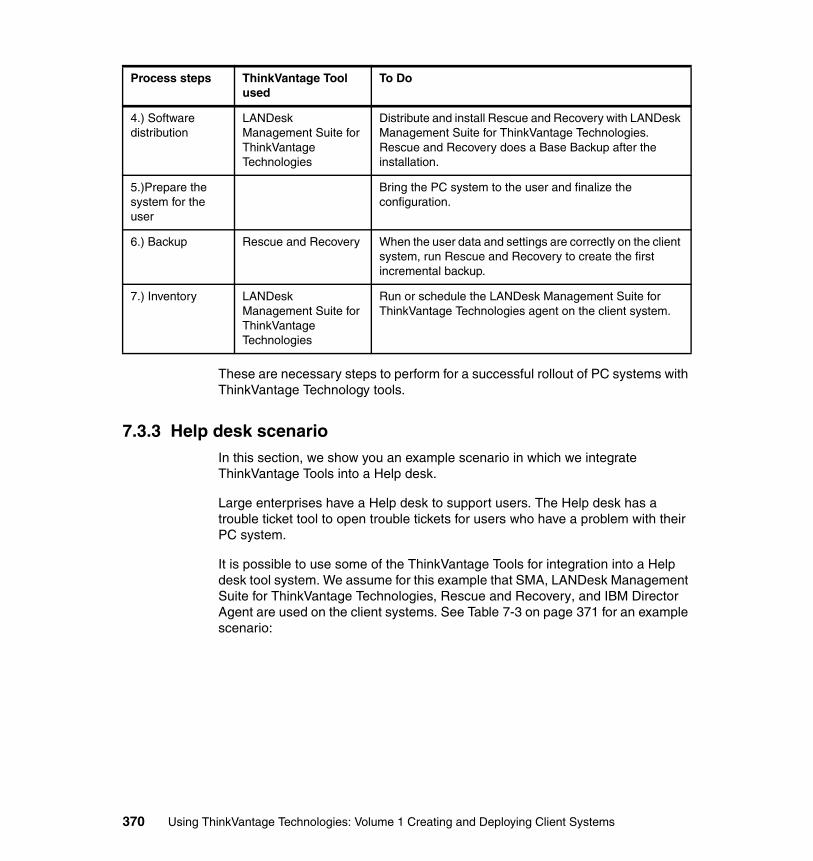
These are necessary steps to perform for a successful rollout of PC systems with ThinkVantage Technology tools.
7.3.3 Help desk scenarioIn this section, we show you an example scenario in which we integrate ThinkVantage Tools into a Help desk.
Large enterprises have a Help desk to support users. The Help desk has a trouble ticket tool to open trouble tickets for users who have a problem with their PC system.
It is possible to use some of the ThinkVantage Tools for integration into a Help desk tool system. We assume for this example that SMA, LANDesk Management Suite for ThinkVantage Technologies, Rescue and Recovery, and IBM Director Agent are used on the client systems. See Table 7-3 on page 371 for an example scenario:
4.) Software distribution
LANDesk Management Suite for ThinkVantage Technologies
Distribute and install Rescue and Recovery with LANDesk Management Suite for ThinkVantage Technologies. Rescue and Recovery does a Base Backup after the installation.
5.)Prepare the system for the user
Bring the PC system to the user and finalize the configuration.
6.) Backup Rescue and Recovery When the user data and settings are correctly on the client system, run Rescue and Recovery to create the first incremental backup.
7.) Inventory LANDesk Management Suite for ThinkVantage Technologies
Run or schedule the LANDesk Management Suite for ThinkVantage Technologies agent on the client system.
Process steps ThinkVantage Tool used
To Do
370 Using ThinkVantage Technologies: Volume 1 Creating and Deploying Client Systems
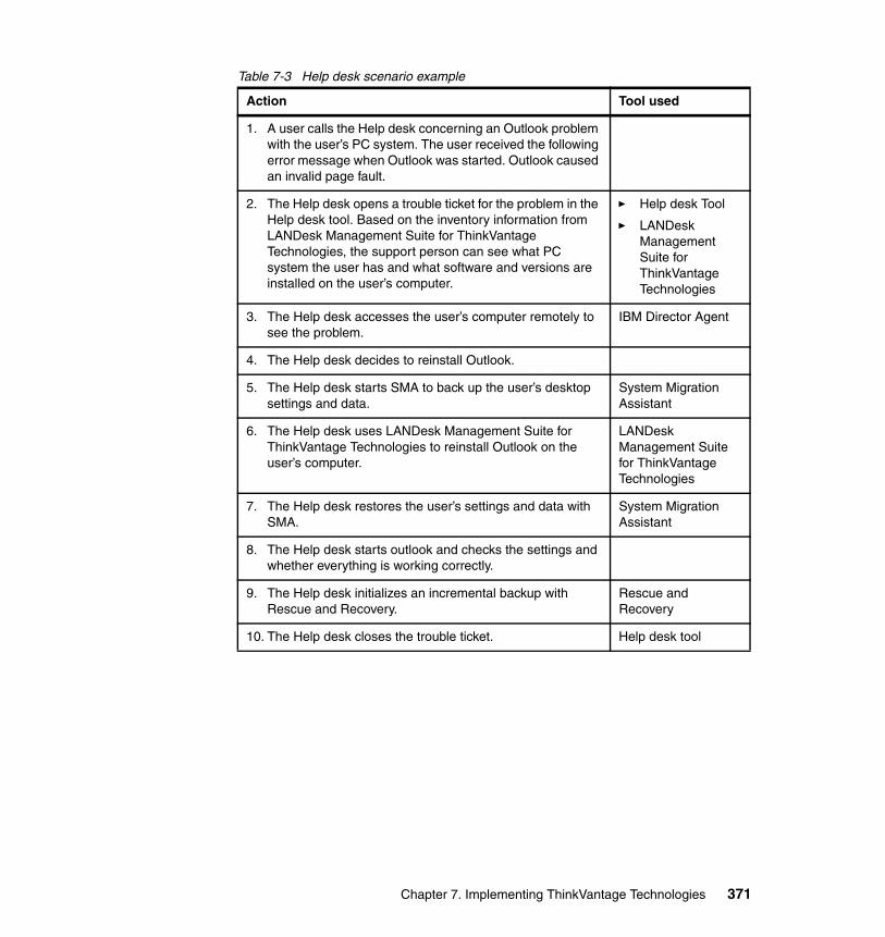
Table 7-3 Help desk scenario example
Action Tool used
1. A user calls the Help desk concerning an Outlook problem with the user’s PC system. The user received the following error message when Outlook was started. Outlook caused an invalid page fault.
2. The Help desk opens a trouble ticket for the problem in the Help desk tool. Based on the inventory information from LANDesk Management Suite for ThinkVantage Technologies, the support person can see what PC system the user has and what software and versions are installed on the user’s computer.
� Help desk Tool
� LANDesk Management Suite for ThinkVantage Technologies
3. The Help desk accesses the user’s computer remotely to see the problem.
IBM Director Agent
4. The Help desk decides to reinstall Outlook.
5. The Help desk starts SMA to back up the user’s desktop settings and data.
System Migration Assistant
6. The Help desk uses LANDesk Management Suite for ThinkVantage Technologies to reinstall Outlook on the user’s computer.
LANDesk Management Suite for ThinkVantage Technologies
7. The Help desk restores the user’s settings and data with SMA.
System Migration Assistant
8. The Help desk starts outlook and checks the settings and whether everything is working correctly.
9. The Help desk initializes an incremental backup with Rescue and Recovery.
Rescue and Recovery
10. The Help desk closes the trouble ticket. Help desk tool
Chapter 7. Implementing ThinkVantage Technologies 371

372 Using ThinkVantage Technologies: Volume 1 Creating and Deploying Client Systems
Appendix A. Smart Image deployment using third party tools
This appendix describes a number of ways you can use third party tools to deploy or assist with the deployment of Smart Images created with ImageUltra Builder.
Topics we include are:
� “Sysprep hardware limitations and HALs” on page 374
� “ImageUltra Builder PXE integration using RIS” on page 375
� “Symantec Ghost” on page 381
� “Symantec DeployCenter” on page 384
� “Image development scenario with DeployCenter” on page 388
� “Image deployment using DeployCenter” on page 405
� “How to access a Windows PE command line” on page 419
� “How to determine the PCI ID of a network card” on page 420
A
© Copyright IBM Corp. 2005. All rights reserved. 373
A.1 Sysprep hardware limitations and HALsWhen you perform hardware imaging using Microsoft's sysprep utility, it is important to understand the hardware dependencies of the resulting image.
Hard disk imaging has traditionally been hindered by the following limitations:
� Differing device drivers between source and target machine: This problem has largely been overcome by Plug-and-Play detection, allowing windows to automatically detect new devices and install the appropriate drivers on the machine. Windows should automatically detect any new devices, but you can run sysprep also with the -pnp option to force a complete Plug-and-Play enumeration on the first boot of the target machine. Use this with caution because it increases the startup time and Microsoft Knowledge Base article number 811428 describes a problem that is caused by the -pnp option. The article recommends against using this parameter.
� Differing hard disk controllers between source and target machine: Traditionally this situation caused an INACCESSIBLE_BOOT_DEVICE blue screen error when booting the target machine. Newer versions of sysprep and the BuildMassStorageSection=Yes option in the sysprep.inf have largely overcome this problem. This causes Windows to load all installed mass storage drivers when the target machine boots. This significantly improves the chances of loading a driver that works with the target hardware.
� Differing Hardware Abstraction Layers (HALs) between the source and target machine: This issue usually results in a STOP 7B blue screen error. There is currently no supported method to overcome this problem. The hardware abstraction layer loads before any of the Windows hardware detection system is running, so there is no way for Windows to detect that it needs to change to a different HAL. At the time of writing, the only real solution to this problem is to create one sysprep image for each HAL that needs to be supported. On modern desktops and laptops, there are typically only two HALs that need to be supported:
– ACPI PIC HAL: Which appears in Device Manager as Advanced Configuration and Power Interface (ACPI) PC
– ACPI APIC HAL: Which appears in Device Manager as ACPI (Uniprocessor PC)
In the past, many images have been created using the ACPI PIC HAL, and these images often work on machines which would normally use the ACPI APIC HAL, but Microsoft does not support this, and some new hardware models require the ACPI APIC HAL and do not work with the PIC HAL. Our testing shows that you can use a single image by simply replacing the HAL.DLL file with the appropriate version prior to booting the target machine
374 Using ThinkVantage Technologies: Volume 1 Creating and Deploying Client Systems
and you can do this with an IUB module. Unfortunately, Microsoft does not support this process, and you should not use it lightly.
At the time of writing, there is no easy way to determine the required Hardware Abstraction Layer for a machine, other than building the machine using the standard Windows setup, and then checking the device under the computer category.
Microsoft Knowledge Base article number 309283 includes a description of the symptoms, when a syspreped image is loaded on a machine with a different HAL. It also includes a list of the HALs, and the machine types on which they are supported.
A.2 ImageUltra Builder PXE integration using RISImageUltra Builder 3.0 by default requires a CD or DVD-ROM drive and media in order to boot a computer and begin the deployment process. In many cases, it is advantageous to be able to start this process by booting from the network using PXE (Pre-boot eXecution Environment). ImageUltra Builder does not currently support this process, but it has been proven to work and the following section describes how you can do it.
Some of the advantages are:
� No requirement for a CD or DVD drive in the machine you are deploying.
� Boot sequence is faster when booting on a 100 Mbps network than from CD.
� You can make changes to the boot system without having to write new CDs.
� Guide users through the process without having to send them a boot CD.
While in theory it is possible to use other PXE servers, booting Windows PE can be very complicated to configure and most products only document booting to DOS or Linux. For this reason, Microsoft’s PXE server, known as Remote Installation Services (RIS) is the only PXE server that we cover in this section.
This section assumes a technical understanding of Remote Installation Services and PXE. The following references provide additional background knowledge:
Important: The PXE specification uses network broadcasts (similar to DHCP). The deployment of Windows PE via PXE involves a significant amount of network traffic. You must thoroughly research the impact on the network utilization and any network hardware configuration requirements before implementation in a production environment.
Appendix A. Smart Image deployment using third party tools 375
� How to set up, configure, and use Remote Installation Services in Windows 2000:
http://support.microsoft.com/?kbid=891275
� How to boot the Windows Preinstall Environment from a RIS server by using PXE-enabled clients:
http://support.microsoft.com/?kbid=304992
� Description of PXE Interaction Among PXE Client, DHCP, and RIS Server
http://support.microsoft.com/?kbid=244036
A.2.1 Adding ImageUltra Builder’s boot CD to a RIS serverYou should clearly understand that this process does not deploy a Remote Installation Services image in the traditional sense. This process adds ImageUltra Builder’s Windows PE environment to the RIS server. Client computers can then boot from the RIS server and start Windows PE (nothing on the computer’s hard disk is touched by Remote Installation Services). Once Windows PE starts, the ImageUltra Builder process begins and connects back to the repository to perform the install exactly as though the machine had been booted from a network deployment CD.
Using Remote Installation Services to boot the ImageUltra Network deployment environment has the following prerequisites:
� A configured RIS server, preferably a server on the local network. Refer to Microsoft documentation, including the document entitled How to set up, configure, and use Remote Installation Services in Windows 2000, at:
http://support.microsoft.com/?kbid=891275
� The target computer’s network card must support the PXE specification.
� The target computer and RIS server must reside in a network environment which allows them to communicate in accordance with the PXE specifications. Specifically the server must be able to receive broadcast packets from the target computer. Refer to the document entitled Description of PXE Interaction Among PXE Client, DHCP, and RIS Server in the Microsoft Knowledge Base at:
http://support.microsoft.com/?kbid=244036
Creating an ImageUltra Builder boot image on the Remote Installation Services server (this process is based on Method 2, documented by Microsoft in Knowledge Base article 304992) requires the following steps:
1. Create a Network Deployment CD using the ImageUltra Builder deployment wizard.
376 Using ThinkVantage Technologies: Volume 1 Creating and Deploying Client Systems
2. On the RIS server, locate the RemoteInstall directory used by the RIS server (this is the directory that is shared as reminst).
3. Under the RemoteInstall directory, navigate to the directory setup\english\images, and create a new directory under images called IUBWinPE (we will refer to this as the ImageUltra RIS image directory).
4. Copy the entire contents of the ImageUltra Builder network boot CD into the new image directory, being sure to include any hidden files.
5. Once the copy is complete, change to the setup\english\images\IUBWinPE\i386 directory, that should now exist on the server, and create a new directory called templates.
6. You must copy the following files into the templates directory:
– startrom.com (find this file in the RemoteInstall\OSChooser\i386 directory on the Remote Installation Services server).
– setupldr.exe (find this file in the i386 directory that you just copied over to the server).
– ntdetect.com (find this file in the i386 directory that you just copied over to the server).
– ristndrd.sif (find this file in the i386\templates directory of any other image currently on the Remote Installation Services server).
7. In the templates directory, rename the file setupldr.exe to ntldr.
8. Edit the file Ristndrd.sif and locate the OSLoadOptions line. Edit the line so that it looks like this:
OsLoadOptions = “/noguiboot /fastdetect /minint”
9. At the bottom of the ristndrd.sif file, modify the [OSChooser] section to give your image a meaningful description on the RIS menu. For example:
[OSChooser]Description = “ImageUltra Builder 3.0”Help = “Boot to the ImageUltra Builder network deployment environment”
10.In the new ImageUltra Remote Installation Services image directory (IUBWinPE), copy the entire contents of the i386\inf directory into the i386 directory.
Note: In some circumstances, the name of the directory used to house the image on the Remote Installation Services server can prevent Windows PE from booting and cause blue screen errors (Stop 0x21a). We have never experienced this problem, but you can find details in Microsoft Knowledge Base article number 308299:
http://support.microsoft.com/?kbid=308299
Appendix A. Smart Image deployment using third party tools 377
In the new ImageUltra RIS image directory, create a file called iubcd.tag (the contents of the file is not important), then right-click the iubcd.tag file and select properties. Tick the Read-only check box, and then click OK. This step is required to trick ImageUltra Builder into thinking it is booting from a CD.
11.Either restart the Remote Installation Services server, or simply restart the RIS service from the services section of the control panel. The service is called Binary Information Negotiation Layer (BINL) on Windows 2000 servers and Remote Installation on Windows 2003 servers.
The ImageUltra Builder Remote Installation Services image is now ready. Any PXE client that is booted from its network card and connected to the RIS server should show the new ImageUltra image on the menu.
By default, the RIS menu displays a number of screens explaining that the hard disk is going to be deleted. These messages appear for any RIS image and do not necessarily reflect what the menu selection actually does. You can customize these menus by modifying or removing particular .osc files on the RIS server, but this is beyond the scope of this redbook. Refer to the following Microsoft document on customizing Remote Installation Services installations:
http://www.microsoft.com/resources/documentation/Windows/XP/all/reskit/en-us/prbc_cai_silp.asp
A.2.2 Creating multiple ImageUltra Builder RIS imagesThere are many cases where it is useful to create multiple ImageUltra Builder Remote Installation Services images. For example:
� Images that connect to different repositories
� Images that are unattended and images that are interactive
� Images that make only certain maps visible
To create a second ImageUltra Builder RIS image, simply copy the entire directory of an existing image, and change its name. The following steps describe the process:
Tip: The account used to logon to the Remote Installation Services server must have permission to create computer accounts in the domain.
We advise you that you configure the NTFS permissions on the ImageUltra RIS image directory so that the account that clients use to log on to the RIS server, during the deployment phase, only has read access.
378 Using ThinkVantage Technologies: Volume 1 Creating and Deploying Client Systems
� If the existing ImageUltra Builder RIS image is in a directory called \RemoteInstall\Setup\English\Images\IUBWinPE, simply copy this directory to a new one called \RemoteInstall\English\Images\IUBWinPE2.
� Then edit the file: \RemoteInstall\English\Images\IUBWinPE2\i386\templates\Ristndrd.sif and modify the Description and Help text in the [OSChooser] section so that it can be differentiated from the previous image.
� Edit the \RemoteInstall\English\Images\IUBWinPE2\PROFILE.INI file to specify the different options for this ImageUltra Builder image. See A.2.3, “Modifying the PROFILE.INI file” on page 379 for more information about the PROFILE.INI file.
It may seem like a waste of space to have a complete copy of the Remote Installation Services image even though we are only changing two files, but when you install RIS, it also installs the Single Instance Storage (SIS) and the Groveler Service which periodically scans all files under the RemoteInstall folder and finds duplicate files. Each duplicate file is copied to a master directory and all other instances of the file are turned into pointers that link to the master copy. This saves large amounts of disk space on the RIS server. The Microsoft Knowledge Base article numbers 299726 and 324447 will be of interest to those who want to learn about the configuration of SIS.
A.2.3 Modifying the PROFILE.INI fileThe PROFILE.INI file which is located in the root directory of the Network Deployment boot CD and in the root directory of the Remote Installation Services image, contains all the options that were selected in the Deploy Wizard during the Network Deployment CD creation. To change any of these options on your RIS image, you can simply edit the PROFILE.INI file instead of having to create a new deployment CD. Common options in this file are:
� The network protocol to use
� The ImageUltra Builder Server’s IP address
� The repository share and directory names
� The user id, password, and domain name for logging onto the repository share
� Whether or not to perform an unattended installation
� The keywords for map file filtering. Keywords must be uppercase. Separate multiple keywords by & (and) to require all keywords match, or | (or) to require that at least one keyword matches.
Appendix A. Smart Image deployment using third party tools 379
Editing this file is particularly useful when making multiple ImageUltra Builder Remote Installation Services images, which is described in A.2.2, “Creating multiple ImageUltra Builder RIS images” on page 378.
A.2.4 TroubleshootingThis section describes common errors that may appear when booting from the Remote Installation Services server and how to resolve them.
� The Operating System image you selected does not contain the necessary drivers for your network adapter
This error occurs when there is no driver INF file in the i386 directory that matches the network card in the computer.
To correct this error, first ensure that all .inf files have been copied from the i386\inf directory into the i386 directory. If this did not resolve the issue, then download the latest windows XP driver for the network card, and add the driver to the Windows PE environment using the instructions in “Adding network device drivers to Windows PE” on page 172.
� File xxx.sys caused an unexpected error (21) at line xxx in d:\..\setup.c
This error occurs if a .inf file was found which matches the network card in the system, but the driver sys file (xxx.sys) referenced by the .inf was not found in the i386\system32\drivers directory.
In some cases, when a driver uses a single .inf file for Windows 2000 and Windows XP drivers, RIS looks for the Windows 2000 driver and Windows PE looks for the XP driver. In this case, it may be necessary to include the driver files for both Windows XP and Windows 2000 in order to avoid this error.
To correct this problem, ensure that the appropriate .inf file and the required .sys driver files for the network card are installed in the correct directories (see “Adding network device drivers to Windows PE” on page 172).
This problem could also arise if there are multiple .inf files that match the network card, and RIS is selecting the wrong one. In this case, search for all .inf files (using Windows search function) that contain a reference to the driver .sys file mentioned in the error message and remove duplicate .inf files if required.
� Failed to install network adapter -- Check WINBOM
This error occurs if any of the files referenced by the network driver’s .inf file are missing or in the wrong directory. This includes additional driver files such as dll, sys, exe, din, or any other file the inf file requires.
For details about the correct directories for all the files and tips about determining the required files, refer to “Adding network device drivers to Windows PE” on page 172.
380 Using ThinkVantage Technologies: Volume 1 Creating and Deploying Client Systems
� There has been an error in the ImageUltra process
This error appears after Windows PE has successfully booted, and the ImageUltra Builder processes begins.
The most common cause of this error is that the iubcd.tag file has not been created in the root directory of the Remote Installation Services image, or the file has not been made read-only (see step on page 378).
A.3 Symantec GhostSymantec Ghost is one of a number of tools for capturing and restoring images of complete hard drives or individual partitions. Use it to capture images that are then used in the creation of both Hardware-Specific (see 2.8, “Hardware-Specific Image” on page 78) and Portable-Sysprep (see 2.9, “Portable-Sysprep Image” on page 99) ImageUltra builds.
When Ghost is used in conjunction with the ImageUltra Builder program, you must consider certain limitations. ImageUltra Builder uses a service partition to store the Smart Image, and consequently, Ghost might encounter problems when attempting to set the size of partitions or when installing an image of a complete hard drive. When defining partition sizes using percentages, Ghost bases these on the total capacity of the hard disk and does not take into account the presence of a service partition. As a result, Ghost might delete the service partition or fail to restore an image. Defining absolute sizes can be equally problematic because drive sizes vary on target computers.
When restoring an image of a complete hard drive, two problems can occur:
� If a service partition existed on the source computer, Ghost includes this service partition as part of the image. When the image is restored, it will overwrite the service partition on the target computer. This results in a mismatch between the contents on the active partition and service partition of the target computer.
� If a service partition does not exist on the source computer, Ghost will assume that it can use the entire hard disk for the image, and will delete the service partition on the target computer.
Due to difficulties managing multiple partitions and images of complete hard drives created by Ghost, ImageUltra Builder supports the following implementations only:
� Restoring single-partition images
� Restoring an image of a complete hard drive, only if the restore process defines a single partition from within the image to be restored.
Appendix A. Smart Image deployment using third party tools 381
The sections below show the basic command line usage of the tool. For more detailed usage, refer to the Ghost manual supplied with the software. A complete list of ghost command line switches can be found by searching:
http://www.symantec.com
for article number 1998082612540625.
A.3.1 Creating an image using Symantec GhostThis section provides information about using Symantec Ghost to capture an image for later use in an ImageUltra Builder Smart Image.
For details about how to access a command prompt in Windows PE in order to run Ghost32, refer to A.7, “How to access a Windows PE command line” on page 419.
Example A-1 shows a simple command line for ghost32 which launches ghost32 interactively, but ensure that you use the -cns parameter (see note above) and that the resulting ghost image is split into 600 MB-sized pieces to facilitate CD distribution. Once ghost launches, you can select the required partitions from the hard disk for inclusion in the image and you can supply the resulting image file name. To avoid issues when creating an ImageUltra Smart Image, we strongly recommend that only one partition is included in the image.
Example: A-1 Using Ghost32 in Windows PE to create an image
ghost32.exe -cns -split=600
A.3.2 Restoring an image using Symantec GhostWhen creating a Hardware Specific Image (HSI) or Portable Sysprep Image (PSI) with ImageUltra Builder, the image restore process needs to be silent (that is, no user interaction). This means all required options must be specified on the
Note: If using Symantec Ghost 6.5 or later (including ghost32.exe) to capture the image, you must use the -cns switch. This forces the traditional naming of spanned files (extensions 001, 002, 003, and so on) that ImageUltra Builder requires.
IUB 2 required that the image file was named image.gho. This limitation no longer applies in IUB 3. We still, however, recommend that a short name (8.3 format) be used for the image files.
382 Using ThinkVantage Technologies: Volume 1 Creating and Deploying Client Systems
command line. The command line is included in the operating system module, allowing ImageUltra Builder to restore the image file automatically.
The following examples describes the process for restoring a single partition from a ghost image (image.gho) to partition 1 on hard disk 1. We strongly recommend that when used within an ImageUltra Smart Image, ghost only ever restore a single partition from an image file. Restoring multiple partitions can create difficulties with the service partition required by ImageUltra Builder.
Create a file named before.txt with the following lines included in the file:
Example: A-2 before.txt file
SELECT DISK 0CREATE PARTITION PRIMARY
Create a file named after.txt with the following lines included in the file:
Example: A-3 after.txt file
SELECT DISK 0SELECT PARTITION 1ASSIGN LETTER=TACTIVE
Create a file named image.bat with the following lines included in the file:
Example: A-4 image.bat file
diskpart.exe /s before.txtghost32.exe -clone,mode=pload,src=image.gho:1,dst=1:1 -auto -sure -quiet -fx -batchdiskpart.ext /s after.txt
Put the following files in the source directory of your repository for use by IUB3 modules:
� after.txt
Note: The before.txt file is used before the ghost image is dropped onto your target machine to prepare the driver for the image. It creates a primary partition on your disk.
Note: The after.txt file is used after the ghost image is dropped onto your target machine. It assigns letter T (drive letter T is what IUB expects it to be) as the drive letter for the partition and makes it the active partition.
Appendix A. Smart Image deployment using third party tools 383
� before.txt
� ghost32.exe
� image.bat
� image.gho
� image.001
� image.002
A.4 Symantec DeployCenterThe following sections include an overview of Symantec DeployCenter and a detailed scenario describing how to use this tool with ImageUltra Builder.
DeployCenter is a component of DeployCenter Library which is in turn a component of Symantec Ghost Solution Suite. The documentation below is based on DeployCenter 5.5.
There is some confusion in the naming of the DeployCenter tools. ImageCenter is the tool used for creating and restoring image files, but the names DeployCenter, ImageCenter, and DriveImage are often used interchangeability.
A.4.1 Overview of Symantec DeployCenterSymantec DeployCenter provides you with proven solutions for system deployment and migration. With Symantec DeployCenter, you can deploy an exact image of a single hard disk to multiple workstations. Symantec DeployCenter includes a number of tools and features, some of which we explain below. For a more complete list of DeployCenter’s functions, refer to the user guide that ships with the product.
A.4.1.1 ImageCenter The ImageCenter application uses SmartSector imaging to create an exact image of a hard disk or partition. You can then use that exact image to deploy Windows workstations, upgrade existing workstations, manage changing desktop environments, and quickly and easily back up and restore hard drives. With ImageCenter, you can create and restore a compressed image file of an entire hard disk or individual partitions of a hard disk on a local drive, across a network, or on a removable media device.
Use ImageCenter to create clone images of Windows 2000 and Windows XP that you can then install on other machines. When making exact duplicates of computer hard disks, it is important to understand some of the potential issues.
384 Using ThinkVantage Technologies: Volume 1 Creating and Deploying Client Systems
Any information that is supposed to be unique for a computer needs to be updated on the cloned machines. This includes computer names and security identifiers (SIDs). Other applications may also have unique computer identifiers which need to be regenerated. Microsoft provides a tool called Sysprep which prepares the operating system for imaging and can generate new names and SIDs for each cloned computer.
A.4.1.2 ImageExplorerImageExplorer is a useful tool for viewing and extracting the contents of an image file without having to restore the image onto a computer. It can even be used to mount the image which is then assigned a drive letter and can then be treated just like any other hard drive. Files and partitions can be copied to and from images. Images can be split into smaller pieces for CD distribution or a split file can be recombined into a single file.
A.4.1.3 Virtual Boot Environment a.k.a. Virtual FloppyThe Virtual Boot Environment (VBE) allows DOS programs to execute from the hard drive on Windows 9X, Windows Me, Windows NT, Windows 2000, and Windows XP platforms as though they are running from a boot floppy. The VBE can be sent to a system remotely eliminating the need to create diskettes and physically take them to the computer. The system will boot into a temporary environment in which it can then run tasks such as capturing or restoring an image, and finally reboot to the original or newly installed operating system.
The Virtual Boot Environment operates by temporarily replacing the Master Boot Record (MBR) boot code on the primary hard drive. Upon rebooting the computer, the new boot code loads and runs the programs stored in the VBE image file. This VBE consists of a loader program, disk I/O redirector TSR program, and a non-compressed floppy boot image file. The boot image file is created from a 1.44 MB or 2.88 MB format bootable floppy. It contains both the bootable OS files, network drivers, and the user application programs just as would exist on a bootable floppy disk.
Upon booting, the VBE loader builds a RAM drive in memory the size of the boot image file, copies the boot image file from the hard drive to memory, and then loads and executes the boot sector within the boot image file. Under DOS, the A: drive is then used to reference the boot image file system. The first physical floppy drive is accessed as drive letter B:.
The Virtual Boot Environment image file is a raw sector-by-sector representation of a floppy file system in either a 1.44 MB or a 2.88 MB floppy disk format. It contains everything that would exist on a bootable floppy disk (boot sector, FATs, directories, and files).
Appendix A. Smart Image deployment using third party tools 385
A.4.1.4 PowerCasting a.k.a. MulticastPowerCasting is DeployCenter’s name for multicasting. Multicasting is a form of network broadcasting which allows a server to send one network packet to many machines instead of having to send an individual packet to each machine. Use this networking technique to dramatically reduce network traffic when deploying an image to many machines at once. This technology is dependent on network hardware that supports multicasting and it should not be used on a production network without first consulting network specialists to ensure that all network hardware is configured correctly to process the multicast packets.
The PowerCasting technology in conjunction with the Virtual Boot Environment (VBE) is an ideal way to deploy multiple systems across an organization. You can include the Symantec DeployCenter imaging tools, scripts, and appropriate network drivers as part of the VBE, allowing multiple systems to pull an image from a central server. Because this task is performed remotely, it eliminates the need to visit the computer and boot using a floppy disk.
A.4.1.5 UnicastingThe Unicast feature lets you create and restore images using a network drive without mapping the drive. It consists of a Unicast server and a Unicast client, which reside on separate machines. You can specify all Unicast parameters on the command line of either the server or the client. The Unicast operation is point-to-point and uses the TCP/IP protocol.
You must start the Unicast server prior to running the Unicast client or before trying to PXE-boot a client machine. Once you have started the server, it requires no user interaction. All Unicast operations are initiated from the client, using either a standard script file or the ImageCenter interface.
A.4.1.6 PXE a.k.a. Network BootPXE (Pre-boot Execution Environment) is part of Intel's WfM (Wired for Management) specification. A computer with a PXE compliant network card can be booted from an image on the network. The diskette images created using DeployCenter’s Boot Disk Builder and VF Editor can be booted over the network using PXE. The PXE server can be used to provide a menu of images to load and can even be configured to provide specific images to specific computers based on their MAC address.
A.4.2 Creating an image using DeployCenterThis section describes how to use the 32bit command line version of DeployCenter (pqideploy.exe). The 32bit version of DeployCenter must be run within Windows PE. For an example of using the DOS version from a PXE boot environment, refer to A.5.1.5, “Capture the donor image” on page 403.
386 Using ThinkVantage Technologies: Volume 1 Creating and Deploying Client Systems
For details about on how to access a command prompt in Windows PE in order to run the pqideploy.exe, refer to A.7, “How to access a Windows PE command line” on page 419.
The 32bit command line version of DeployCenter has no graphical interface, so it must be controlled using a script and command line parameters. For a complete list of command line parameters, search:
http://www.symantec.com
for document number 2004078077820962.
Example A-5 shows a script file to capture an image of partition 1 on drive 1 using low compression.
Example: A-5 DeployCenter script file for capturing an image (capture.scp)
SELECT DRIVE 1SELECT PARTITION 1STORE WITH COMPRESSION LOW
Example A-6 shows the command line that utilizes the previous script (capture.scp). The /NRB specifies no reboot and the /MFS specifies the maximum size of a file, causing DeployCenter to split the image into files no greater than 600 MB.
Example: A-6 DeployCenter command line for capturing an image using a script file
pqideploy.exe /CMD=capture.scp /NRB /MFS=600M /IMG=image.pqi
A.4.3 Restoring an image with DeployCenterWhen creating a Hardware Specific Image (HSI) or Portable Sysprep Image (PSI) with ImageUltra Builder, the image restore process needs to be silent (that is, no user interaction). This means that all required options must be specified on the command line. The command line is included in the operating system module, allowing ImageUltra Builder to restore the image file automatically.
ImageUltra Builder 3.0 now uses 32bit Windows PE as its deployment environment. Consequently, the 32bit command line version of DeployCenter (pqideploy.exe) must be used.
When using DeployCenter, a script file must be created to perform silent restores. Example A-7 shows an example script file (restore.scp) that can be used to restore an image file and ensure that the service partition remains intact.
Appendix A. Smart Image deployment using third party tools 387
Example: A-7 DeployCenter script file for restoring an image (restore.scp)
SELECT DRIVE 1PROTECT PARTITION LASTSELECT FREESPACE FIRSTSELECT IMAGE 1RESIZE IMAGE PROPORTIONALSELECT IMAGE 2RESIZE IMAGE 2048RESTORESELECT PARTITION 1SET ACTIVESELECT PARTITION 2UNHIDE
Example A-8 shows the command line that would be used to load the image (image.pqi) using the script (restore.scp). The /NRB specifies no reboot. For a complete list of command line parameters, search:
http://www.symantec.com
for document number 2004078077820962.
Example: A-8 DeployCenter command line for restoring an image using a script file
pqideploy.exe /CMD=restore.scp /NRB /IMG=image.pqi
A.5 Image development scenario with DeployCenterThis section describes a scenario which demonstrates one way in which you can use DeployCenter and ImageUltra Builder together.
Prerequisite:
� Create a donor or seed Portable-Sysprep Image (PSI). We document this in section 2.9, “Portable-Sysprep Image” on page 99.
DeployCenter is then used to create an image of the hard disk and that image is added to the ImageUltra Builder repository as a Portable-Sysprep Image.
ImageUltra Builder is used to deploy the Portable-Sysprep image to the service partition of the machine and finally DeployCenter is used again to capture an image of the computer in the deployed state. The resulting image can then be used for a mass rollout.
388 Using ThinkVantage Technologies: Volume 1 Creating and Deploying Client Systems
One of the advantages to this method is that the portable-sysprep Smart Image can be configured to use Network Sync (see page 24) to check for updated maps and modules on the ImageUltra Builder server before it begins the install.
The following sections guide you through the process:
� A.5.1, “Preparing and capturing the donor image using PXE” on page 389
� A.5.2, “Add the Portable-Sysprep Image to the ImageUltra repository” on page 404
� A.5.3, “Deploy and clone the Portable-Sysprep Image” on page 404
A.5.1 Preparing and capturing the donor image using PXEYou can perform this process using either Windows PE and the 32bit pqideploy.exe program, or using a DOS network boot diskette and the DOS version of DeployCenter. This section, however, describes an alternative using PXE (network boot) to load a virtual DOS network boot disk.
Prepare the donor or seed image in accordance with section 2.9.1, “Preparing the seed system for the Portable-Sysprep Image” on page 100.
Once the image is prepared, use the following method to capture the DeployCenter image of the partition.
� A.5.1.1, “Confirm PXE service is installed correctly” on page 389
� A.5.1.2, “Add a network driver to the Boot Disk Builder” on page 390
� A.5.1.3, “Create a virtual boot diskette” on page 397
� A.5.1.4, “Add the virtual diskette to the PXE client menu” on page 402
� A.5.1.5, “Capture the donor image” on page 403
A.5.1.1 Confirm PXE service is installed correctlyPerform the following steps to check that PXE is installed:
1. Click Start → Programs → PowerQuest DeployCenter 5.5 Tools.
2. Ensure that the PXE Configuration Utility is listed.
3. If it is not available, install the PXE option provided with the DeployCenter media.
The following steps confirm that the PXE services are installed and running:
Note: You need to have a DHCP Server installed to use this cloning method. For these examples, we used a Windows 2000 server.
Appendix A. Smart Image deployment using third party tools 389
1. Right-click My Computer.
2. Select Manage.
3. Expand Services and Applications and select Services.
4. On the right panel, scroll down and locate PowerQuest PXE MTFTP Service and PowerQuest PXE Service.
5. Ensure that the services are listed as Started.
A.5.1.2 Add a network driver to the Boot Disk BuilderThe DeployCenter Boot Disk Builder (see Figure A-1 on page 391) includes many predefined network drivers. In the event that the network driver you need for the client is not available, you must add the network client you need to the Boot Disk Builder. The following section describes the process of adding a new driver. If, however, the driver you require is already available, skip to section A.5.1.3, “Create a virtual boot diskette” on page 397.
Prerequisites:
� You must know the PCI ID of the network adapter for which you are adding the driver (see A.8, “How to determine the PCI ID of a network card” on page 420).
These instructions describe how to add a network driver to the Boot Disk Builder:
1. Create a share called IMAGES on your server.
2. Download and extract the latest DOS network driver for your client and save it onto a folder on your deployment server.
3. Select Start → Programs → PowerQuest DeployCenter 5.5 → DeployCenter 5.5 Tools → Boot Disk Builder.
4. Select Microsoft TCP/IP Boot Disk.
Important: The DHCP configuration requirements differ depending on whether the PXE server is installed on the DHCP server or on a different server. Refer to the DeployCenter User Guide for details about configuring the DHCP server correctly.
390 Using ThinkVantage Technologies: Volume 1 Creating and Deploying Client Systems
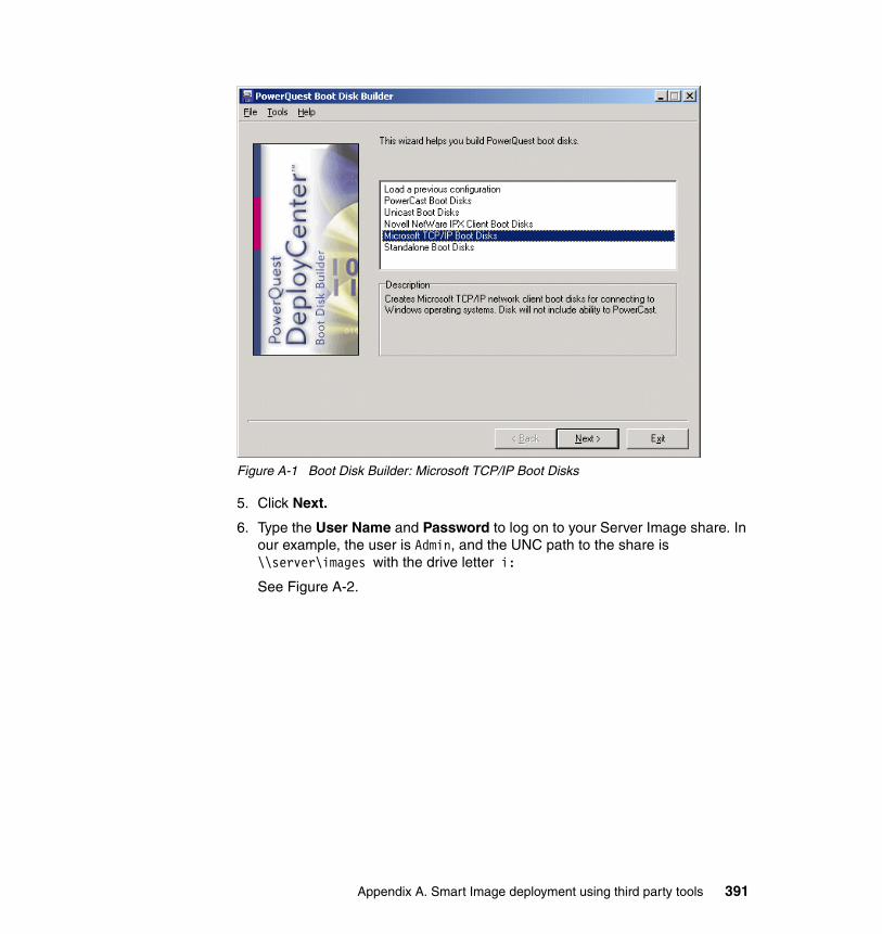
Figure A-1 Boot Disk Builder: Microsoft TCP/IP Boot Disks
5. Click Next.
6. Type the User Name and Password to log on to your Server Image share. In our example, the user is Admin, and the UNC path to the share is \\server\images with the drive letter i:
See Figure A-2.
Appendix A. Smart Image deployment using third party tools 391
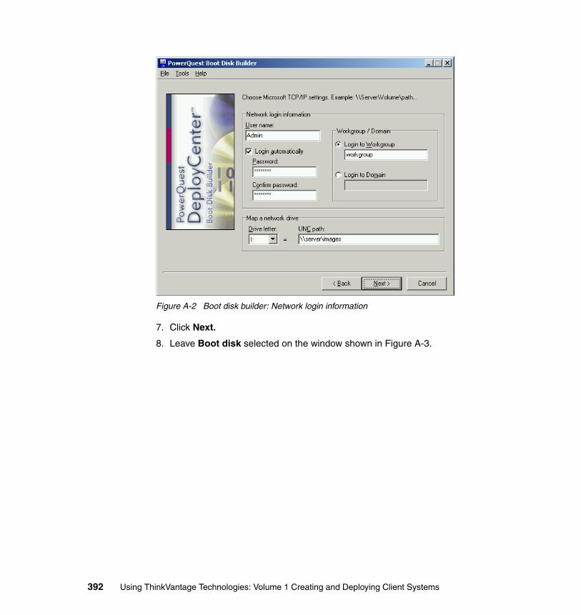
Figure A-2 Boot disk builder: Network login information
7. Click Next.
8. Leave Boot disk selected on the window shown in Figure A-3.
392 Using ThinkVantage Technologies: Volume 1 Creating and Deploying Client Systems
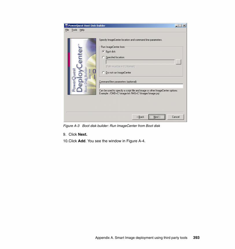
Figure A-3 Boot disk builder: Run ImageCenter from Boot disk
9. Click Next.
10.Click Add. You see the window in Figure A-4.
Appendix A. Smart Image deployment using third party tools 393
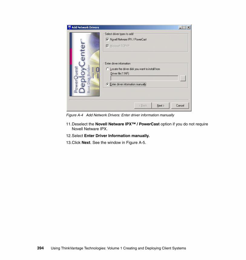
Figure A-4 Add Network Drivers: Enter driver information manually
11.Deselect the Novell Netware IPX™ / PowerCast option if you do not require Novell Netware IPX.
12.Select Enter Driver Information manually.
13.Click Next. See the window in Figure A-5.
394 Using ThinkVantage Technologies: Volume 1 Creating and Deploying Client Systems
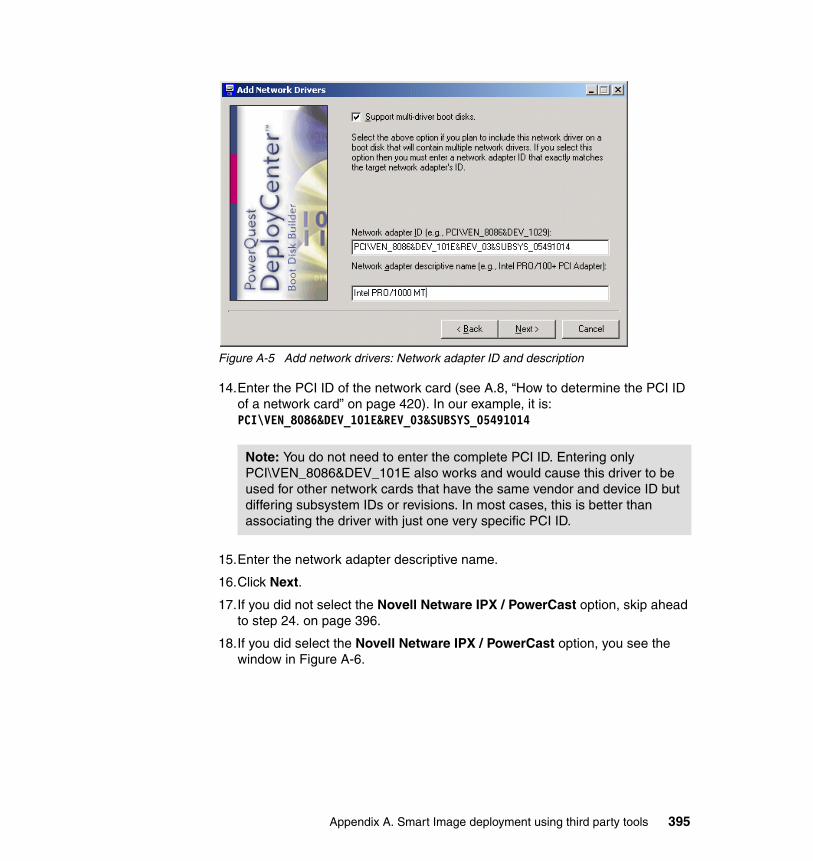
Figure A-5 Add network drivers: Network adapter ID and description
14.Enter the PCI ID of the network card (see A.8, “How to determine the PCI ID of a network card” on page 420). In our example, it is: PCI\VEN_8086&DEV_101E&REV_03&SUBSYS_05491014
15.Enter the network adapter descriptive name.
16.Click Next.
17.If you did not select the Novell Netware IPX / PowerCast option, skip ahead to step 24. on page 396.
18.If you did select the Novell Netware IPX / PowerCast option, you see the window in Figure A-6.
Note: You do not need to enter the complete PCI ID. Entering only PCI\VEN_8086&DEV_101E also works and would cause this driver to be used for other network cards that have the same vendor and device ID but differing subsystem IDs or revisions. In most cases, this is better than associating the driver with just one very specific PCI ID.
Appendix A. Smart Image deployment using third party tools 395
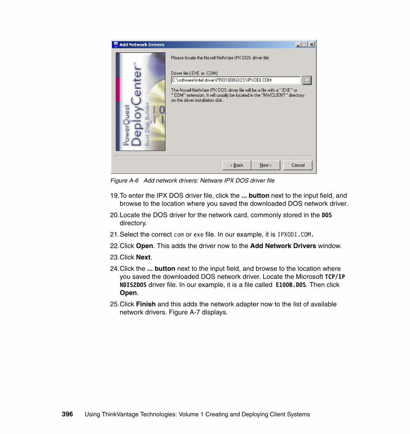
Figure A-6 Add network drivers: Netware IPX DOS driver file
19.To enter the IPX DOS driver file, click the ... button next to the input field, and browse to the location where you saved the downloaded DOS network driver.
20.Locate the DOS driver for the network card, commonly stored in the DOS directory.
21.Select the correct com or exe file. In our example, it is IPXODI.COM.
22.Click Open. This adds the driver now to the Add Network Drivers window.
23.Click Next.
24.Click the ... button next to the input field, and browse to the location where you saved the downloaded DOS network driver. Locate the Microsoft TCP/IP NDIS2DOS driver file. In our example, it is a file called E100B.DOS. Then click Open.
25.Click Finish and this adds the network adapter now to the list of available network drivers. Figure A-7 displays.
396 Using ThinkVantage Technologies: Volume 1 Creating and Deploying Client Systems
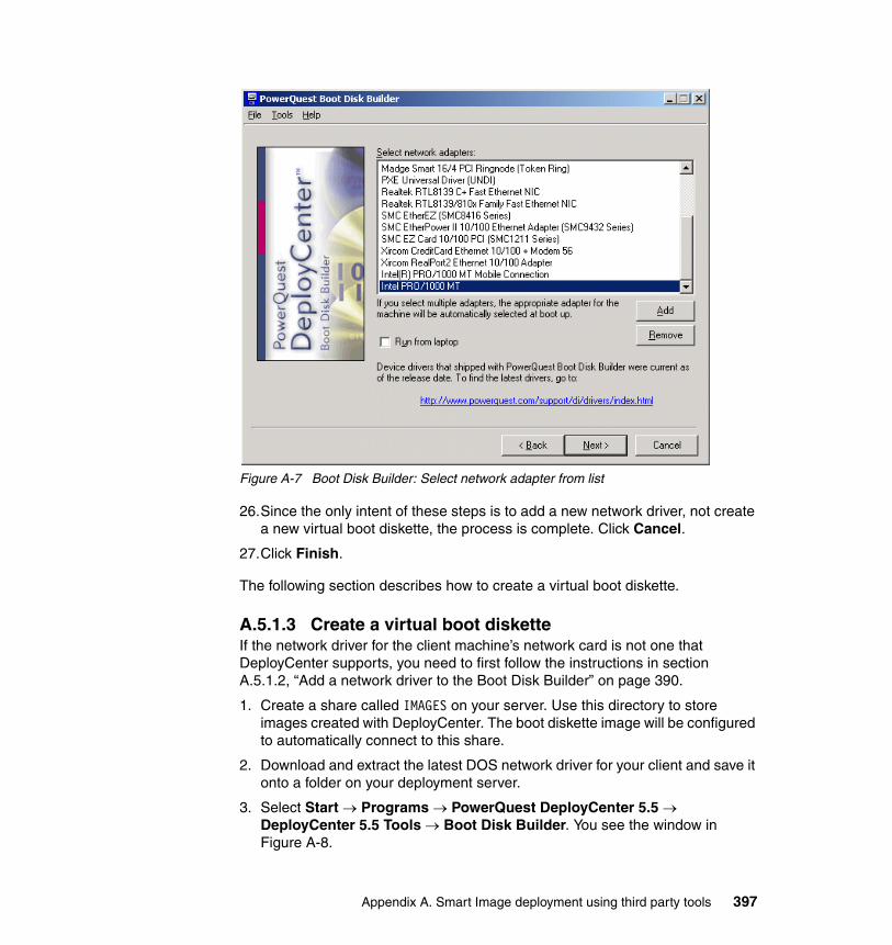
Figure A-7 Boot Disk Builder: Select network adapter from list
26.Since the only intent of these steps is to add a new network driver, not create a new virtual boot diskette, the process is complete. Click Cancel.
27.Click Finish.
The following section describes how to create a virtual boot diskette.
A.5.1.3 Create a virtual boot disketteIf the network driver for the client machine’s network card is not one that DeployCenter supports, you need to first follow the instructions in section A.5.1.2, “Add a network driver to the Boot Disk Builder” on page 390.
1. Create a share called IMAGES on your server. Use this directory to store images created with DeployCenter. The boot diskette image will be configured to automatically connect to this share.
2. Download and extract the latest DOS network driver for your client and save it onto a folder on your deployment server.
3. Select Start → Programs → PowerQuest DeployCenter 5.5 → DeployCenter 5.5 Tools → Boot Disk Builder. You see the window in Figure A-8.
Appendix A. Smart Image deployment using third party tools 397
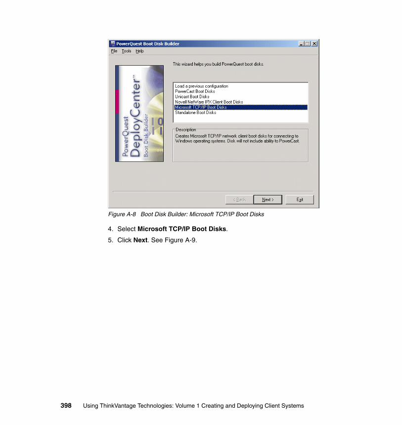
Figure A-8 Boot Disk Builder: Microsoft TCP/IP Boot Disks
4. Select Microsoft TCP/IP Boot Disks.
5. Click Next. See Figure A-9.
398 Using ThinkVantage Technologies: Volume 1 Creating and Deploying Client Systems
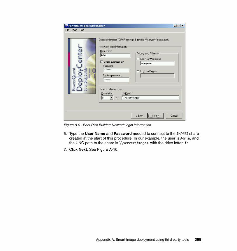
Figure A-9 Boot Disk Builder: Network login information
6. Type the User Name and Password needed to connect to the IMAGES share created at the start of this procedure. In our example, the user is Admin, and the UNC path to the share is \\server\images with the drive letter i:
7. Click Next. See Figure A-10.
Appendix A. Smart Image deployment using third party tools 399
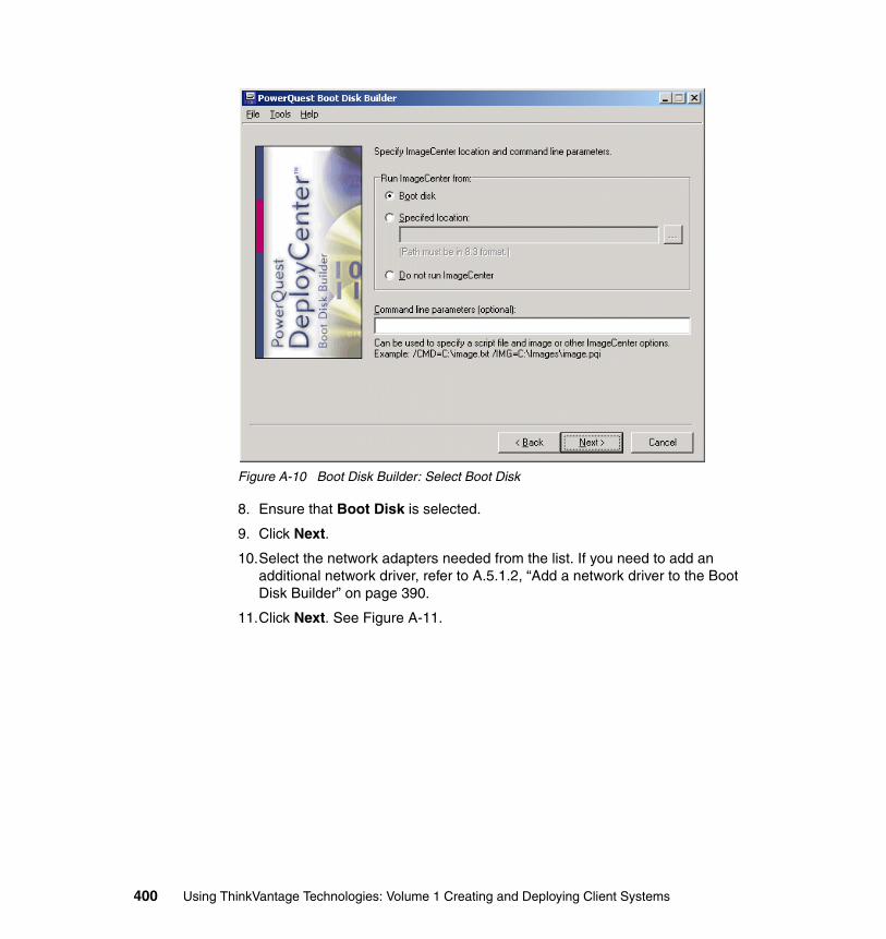
Figure A-10 Boot Disk Builder: Select Boot Disk
8. Ensure that Boot Disk is selected.
9. Click Next.
10.Select the network adapters needed from the list. If you need to add an additional network driver, refer to A.5.1.2, “Add a network driver to the Boot Disk Builder” on page 390.
11.Click Next. See Figure A-11.
400 Using ThinkVantage Technologies: Volume 1 Creating and Deploying Client Systems
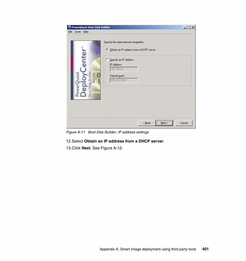
Figure A-11 Boot Disk Builder: IP address settings
12.Select Obtain an IP address from a DHCP server.
13.Click Next. See Figure A-12.
Appendix A. Smart Image deployment using third party tools 401
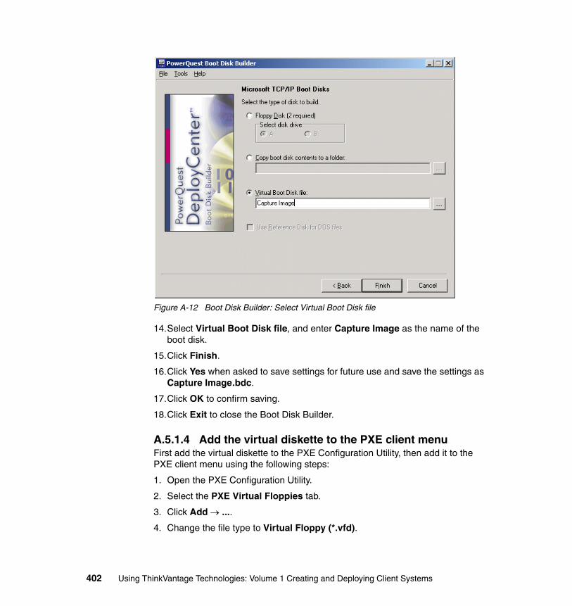
Figure A-12 Boot Disk Builder: Select Virtual Boot Disk file
14.Select Virtual Boot Disk file, and enter Capture Image as the name of the boot disk.
15.Click Finish.
16.Click Yes when asked to save settings for future use and save the settings as Capture Image.bdc.
17.Click OK to confirm saving.
18.Click Exit to close the Boot Disk Builder.
A.5.1.4 Add the virtual diskette to the PXE client menuFirst add the virtual diskette to the PXE Configuration Utility, then add it to the PXE client menu using the following steps:
1. Open the PXE Configuration Utility.
2. Select the PXE Virtual Floppies tab.
3. Click Add → ....
4. Change the file type to Virtual Floppy (*.vfd).
402 Using ThinkVantage Technologies: Volume 1 Creating and Deploying Client Systems
5. Browse to C:\Program Files\PowerQuest\DeployCenter 5.5\BDBUILD (this is the default save directory for virtual floppies).
6. Select Capture Image.vfd and click Open.
7. Click OK.
8. Select the PXE client menu tab.
9. Click Add.
10.Under PXE client menu name, type Capture Image.
11.Below Virtual Floppy Assigned, select Capture Image.1.
12.Click OK → Exit.
You have now configured DeployCenter PXE to allow the manual capture of an image from the donor (or seed) system and saved it to the I: drive which will be mapped to the \\server\images share.
A.5.1.5 Capture the donor image Once you have prepared the donor system to be imaged, use the instructions below to create a donor image on the server.
1. Power on the donor system.
2. When you see the IBM image, press F12 to access the alternative boot menu.
3. Select the network boot device (be aware that not all computers support network boot, and some network cards may require firmware upgrades to conform to the latest PXE specifications).
In our example, we use the IBA 4.0.22 Slot 0240.
4. Press Enter.
5. When you see “Please select from the following items:”, select Capture Image using the tab key.
6. Press Enter.
7. After a few seconds, you see the ImageCenter main menu window.
8. Click Create Image.
9. Press Enter.
10.Type the name of your image file. Use the complete path and image file name. Remember that when the virtual floppy was created, it was configured to map I: drive to \\server\images, so, for this example, use I:\IUBWXP.PQI as the image name.
11.Add a description of the donor image you are creating in the Image File Comments: field. This is version 1.1 that contains Windows XP Portable
Appendix A. Smart Image deployment using third party tools 403
Sysprep image with the following changes, Updated MassStorage list in sysprep.inf.
12.Use the tab key to select Next.
13.On the Compress Image File window, select High Compression.
14.Select Next.
15.The next window contains the details of your donor image, hard drive size, and image file to be saved and level of compression used.
16.Review the options under the Advanced Options button.
17.When you have reviewed all settings, click Finish.
18.ImageCenter now starts cloning your client image and stores it as a donor image onto your network share.
19.When image capture completes, you see a confirmation window. Review the window and confirm there were no errors during the image creation.
20.Close the ImageCenter.
21.Power off the client.
You now have the ImageCenter Donor image stored on the Image server and ready for use by ImageUltra Builder.
A.5.2 Add the Portable-Sysprep Image to the ImageUltra repositoryTo add the newly created image to the ImageUltra repository as a Portable-Sysprep Image, refer to 2.9.2, “Using a Traditional Image in a Portable-Sysprep Image solution” on page 102.
A.5.3 Deploy and clone the Portable-Sysprep ImageIn this section, we deploy the ImageUltra Builder Smart Image to a client service partition. Then we clone the client hard disk content to an imaging server. Then we can distribute the cloned image, using either unicast or multicast, to clients with the same configuration. This cloning method is very useful for large rollouts of the same system configuration.
The following steps describe the high level process:
1. Deploy the portable-sysprep image with ImageUltra Builder, using the Install and Stop method. For detailed steps about deploying an image by using Install and Stop, refer to 2.11.5, “Install phase” on page 162.
Once the deploy completes, the donor is in the deployed state. This means that on the next boot, the computer boots from the service partition and begins installing the operating system. One of the advantages to this method
404 Using ThinkVantage Technologies: Volume 1 Creating and Deploying Client Systems
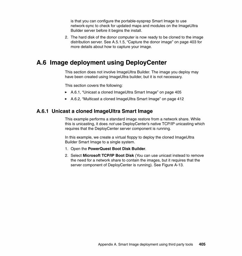
is that you can configure the portable-sysprep Smart Image to use network-sync to check for updated maps and modules on the ImageUltra Builder server before it begins the install.
2. The hard disk of the donor computer is now ready to be cloned to the image distribution server. See A.5.1.5, “Capture the donor image” on page 403 for more details about how to capture your image.
A.6 Image deployment using DeployCenterThis section does not involve ImageUltra Builder. The image you deploy may have been created using ImageUltra builder, but it is not necessary.
This section covers the following:
� A.6.1, “Unicast a cloned ImageUltra Smart Image” on page 405
� A.6.2, “Multicast a cloned ImageUltra Smart Image” on page 412
A.6.1 Unicast a cloned ImageUltra Smart ImageThis example performs a standard image restore from a network share. While this is unicasting, it does not use DeployCenter’s native TCP/IP unicasting which requires that the DeployCenter server component is running.
In this example, we create a virtual floppy to deploy the cloned ImageUltra Builder Smart Image to a single system.
1. Open the PowerQuest Boot Disk Builder.
2. Select Microsoft TCP/IP Boot Disk (You can use unicast instead to remove the need for a network share to contain the images, but it requires that the server component of DeployCenter is running). See Figure A-13.
Appendix A. Smart Image deployment using third party tools 405
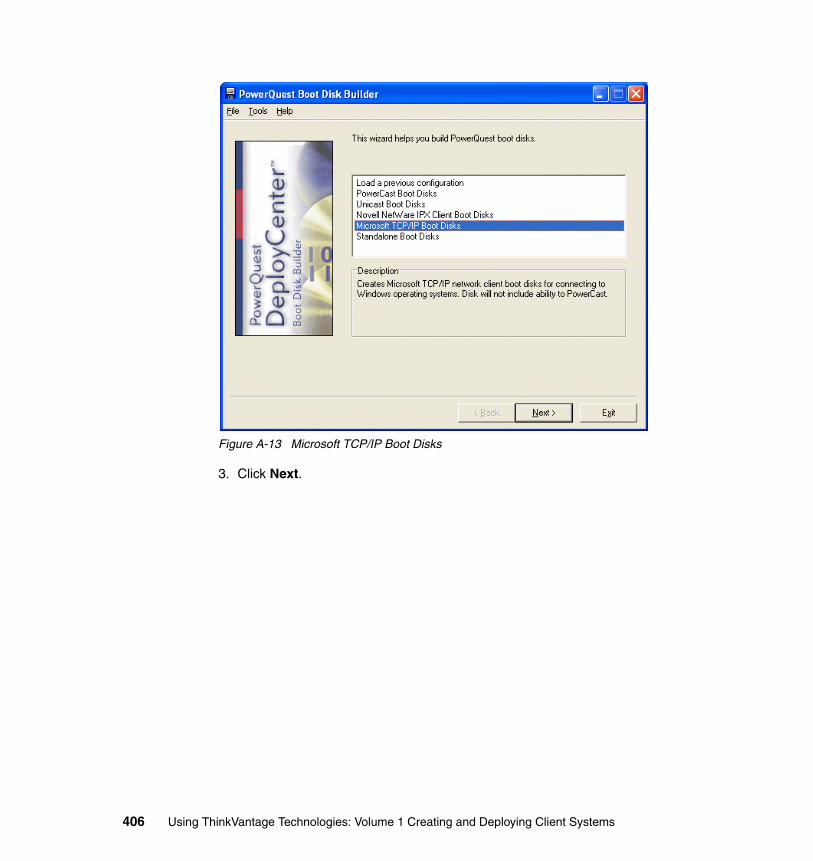
Figure A-13 Microsoft TCP/IP Boot Disks
3. Click Next.
406 Using ThinkVantage Technologies: Volume 1 Creating and Deploying Client Systems
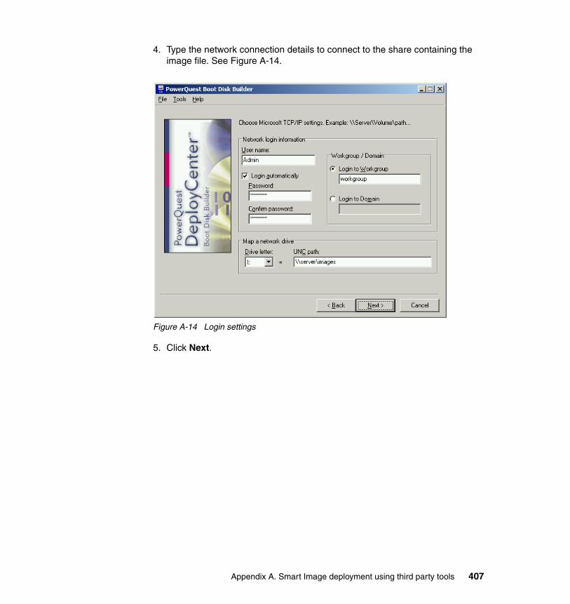
4. Type the network connection details to connect to the share containing the image file. See Figure A-14.
Figure A-14 Login settings
5. Click Next.
Appendix A. Smart Image deployment using third party tools 407
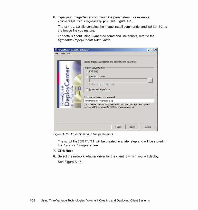
6. Type your ImageCenter command line parameters. For example: /cmd=script.txt /img=basexp.pqi. See Figure A-15.
The script.txt file contains the image install commands, and BASEXP.PQI is the image file you restore.
For details about using Symantec command line scripts, refer to the Symantec DeployCenter User Guide.
Figure A-15 Enter Command line parameters
The script file SCRIPT.TXT will be created in a later step and will be stored in the \\server\images share.
7. Click Next.
8. Select the network adapter driver for the client to which you will deploy.
See Figure A-16.
408 Using ThinkVantage Technologies: Volume 1 Creating and Deploying Client Systems
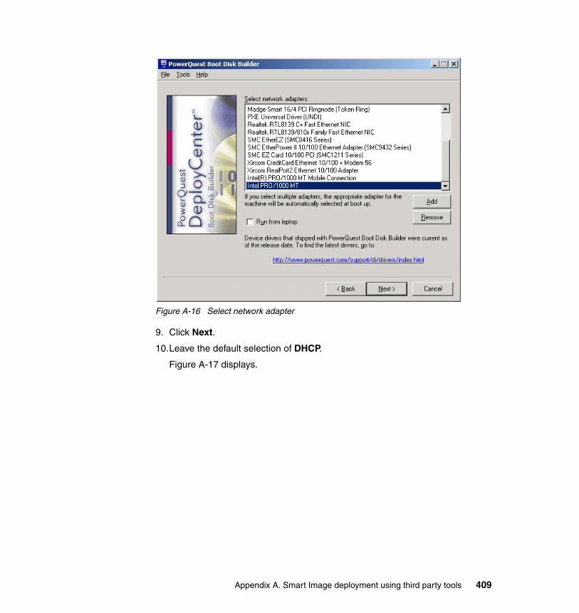
Figure A-16 Select network adapter
9. Click Next.
10.Leave the default selection of DHCP.
Figure A-17 displays.
Appendix A. Smart Image deployment using third party tools 409
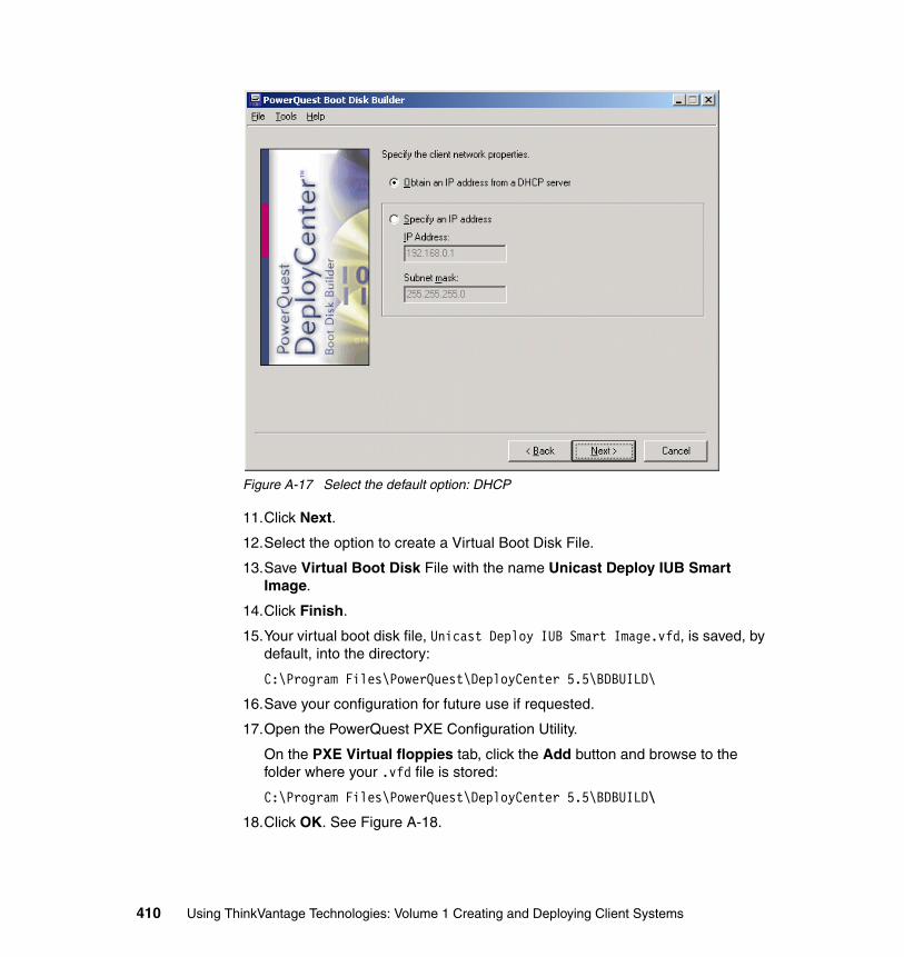
Figure A-17 Select the default option: DHCP
11.Click Next.
12.Select the option to create a Virtual Boot Disk File.
13.Save Virtual Boot Disk File with the name Unicast Deploy IUB Smart Image.
14.Click Finish.
15.Your virtual boot disk file, Unicast Deploy IUB Smart Image.vfd, is saved, by default, into the directory:
C:\Program Files\PowerQuest\DeployCenter 5.5\BDBUILD\
16.Save your configuration for future use if requested.
17.Open the PowerQuest PXE Configuration Utility.
On the PXE Virtual floppies tab, click the Add button and browse to the folder where your .vfd file is stored:
C:\Program Files\PowerQuest\DeployCenter 5.5\BDBUILD\
18.Click OK. See Figure A-18.
410 Using ThinkVantage Technologies: Volume 1 Creating and Deploying Client Systems
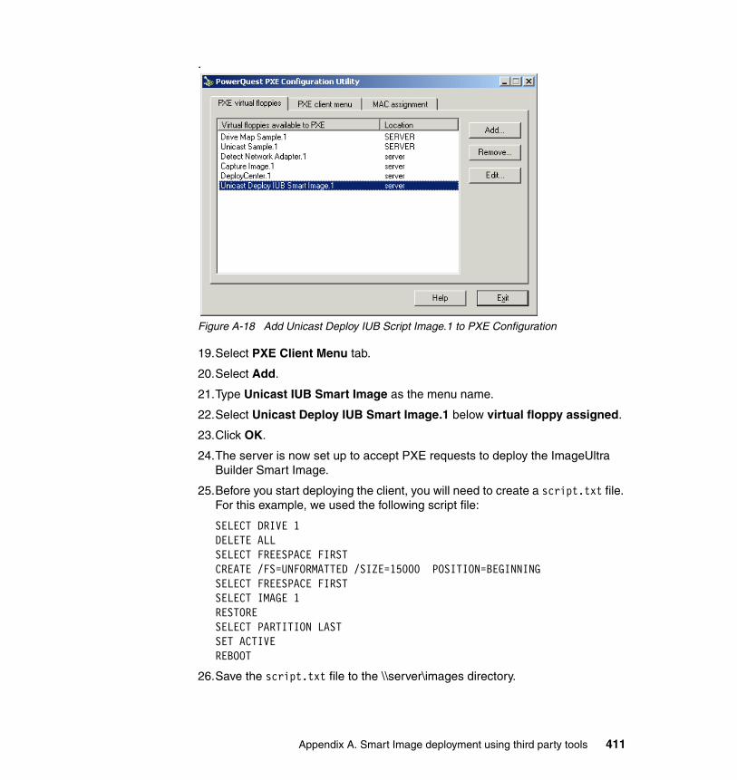
.
Figure A-18 Add Unicast Deploy IUB Script Image.1 to PXE Configuration
19.Select PXE Client Menu tab.
20.Select Add.
21.Type Unicast IUB Smart Image as the menu name.
22.Select Unicast Deploy IUB Smart Image.1 below virtual floppy assigned.
23.Click OK.
24.The server is now set up to accept PXE requests to deploy the ImageUltra Builder Smart Image.
25.Before you start deploying the client, you will need to create a script.txt file. For this example, we used the following script file:
SELECT DRIVE 1DELETE ALLSELECT FREESPACE FIRSTCREATE /FS=UNFORMATTED /SIZE=15000 POSITION=BEGINNINGSELECT FREESPACE FIRSTSELECT IMAGE 1RESTORESELECT PARTITION LASTSET ACTIVEREBOOT
26.Save the script.txt file to the \\server\images directory.
Appendix A. Smart Image deployment using third party tools 411
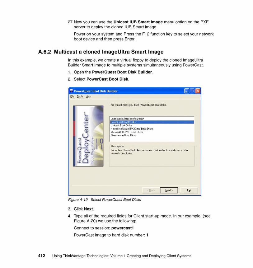
27.Now you can use the Unicast IUB Smart Image menu option on the PXE server to deploy the cloned IUB Smart image.
Power on your system and Press the F12 function key to select your network boot device and then press Enter.
A.6.2 Multicast a cloned ImageUltra Smart ImageIn this example, we create a virtual floppy to deploy the cloned ImageUltra Builder Smart Image to multiple systems simultaneously using PowerCast.
1. Open the PowerQuest Boot Disk Builder.
2. Select PowerCast Boot Disk.
Figure A-19 Select PowerQuest Boot Disks
3. Click Next.
4. Type all of the required fields for Client start-up mode. In our example, (see Figure A-20) we use the following:
Connect to session: powercast1
PowerCast image to hard disk number: 1
412 Using ThinkVantage Technologies: Volume 1 Creating and Deploying Client Systems
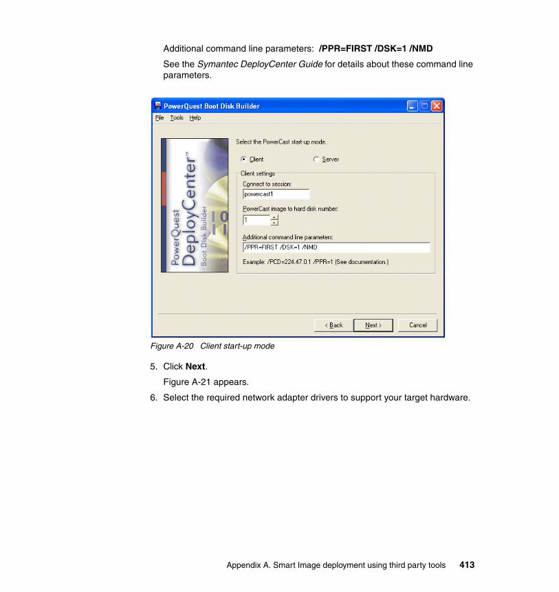
Additional command line parameters: /PPR=FIRST /DSK=1 /NMD
See the Symantec DeployCenter Guide for details about these command line parameters.
Figure A-20 Client start-up mode
5. Click Next.
Figure A-21 appears.
6. Select the required network adapter drivers to support your target hardware.
Appendix A. Smart Image deployment using third party tools 413
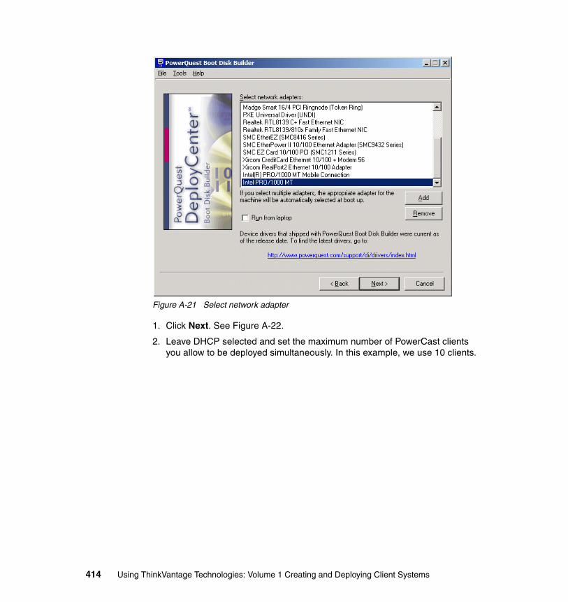
Figure A-21 Select network adapter
1. Click Next. See Figure A-22.
2. Leave DHCP selected and set the maximum number of PowerCast clients you allow to be deployed simultaneously. In this example, we use 10 clients.
414 Using ThinkVantage Technologies: Volume 1 Creating and Deploying Client Systems
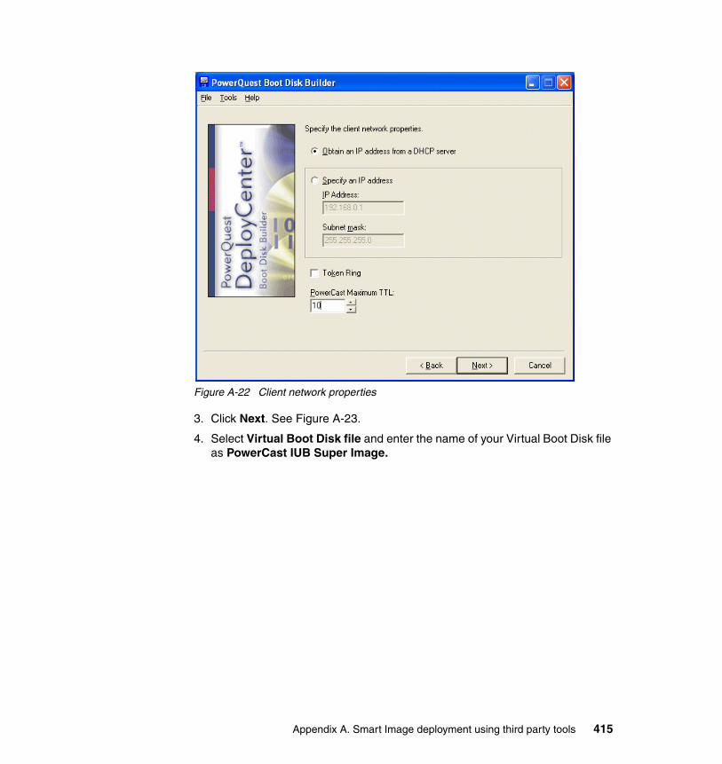
Figure A-22 Client network properties
3. Click Next. See Figure A-23.
4. Select Virtual Boot Disk file and enter the name of your Virtual Boot Disk file as PowerCast IUB Super Image.
Appendix A. Smart Image deployment using third party tools 415
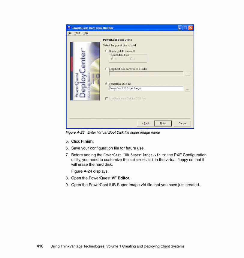
Figure A-23 Enter Virtual Boot Disk file super image name
5. Click Finish.
6. Save your configuration file for future use.
7. Before adding the PowerCast IUB Super Image.vfd to the PXE Configuration utility, you need to customize the autoexec.bat in the virtual floppy so that it will erase the hard disk.
Figure A-24 displays.
8. Open the PowerQuest VF Editor.
9. Open the PowerCast IUB Super Image.vfd file that you have just created.
416 Using ThinkVantage Technologies: Volume 1 Creating and Deploying Client Systems
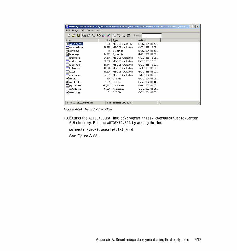
Figure A-24 VF Editor window
10.Extract the AUTOEXEC.BAT into c:\program files\PowerQuest\DeployCenter 5.5 directory. Edit the AUTOEXEC.BAT, by adding the line:
pqimgctr /cmd=i:\pscript.txt /nrd
See Figure A-25.
Appendix A. Smart Image deployment using third party tools 417
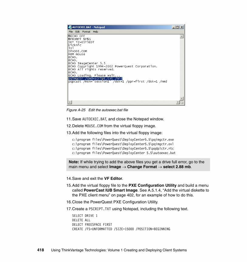
Figure A-25 Edit the autoexec.bat file
11.Save AUTOEXEC.BAT, and close the Notepad window.
12.Delete MOUSE.COM from the virtual floppy image.
13.Add the following files into the virtual floppy image:
c:\program files\PowerQuest\DeployCenter5.5\pqimgctr.exec:\program files\PowerQuest\DeployCenter5.5\pqimgctr.ovlc:\program files\PowerQuest\DeployCenter5.5\pqdplctr.rtcc:\program files\PowerQuest\DeployCenter 5.5\autoexec.bat
14.Save and exit the VF Editor.
15.Add the virtual floppy file to the PXE Configuration Utility and build a menu called PowerCast IUB Smart Image. See A.5.1.4, “Add the virtual diskette to the PXE client menu” on page 402, for an example of how to do this.
16.Close the PowerQuest PXE Configuration Utility.
17.Create a PSCRIPT.TXT using Notepad, including the following text.
SELECT DRIVE 1DELETE ALLDELECT FREESPACE FIRSTCREATE /FS=UNFORMATTED /SIZE=15000 /POSITION=BEGINNING
Note: If while trying to add the above files you get a drive full error, go to the main menu and select Image → Change Format → select 2.88 mb.
418 Using ThinkVantage Technologies: Volume 1 Creating and Deploying Client Systems
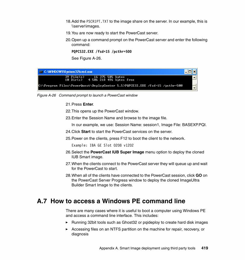
18.Add the PSCRIPT.TXT to the image share on the server. In our example, this is \\server\images.
19.You are now ready to start the PowerCast server.
20.Open up a command prompt on the PowerCast server and enter the following command:
PQPCS32.EXE /fsd=15 /pcthr=500
See Figure A-26.
Figure A-26 Command prompt to launch a PowerCast window
21.Press Enter.
22.This opens up the PowerCast window.
23.Enter the Session Name and browse to the image file.
In our example, we use: Session Name: session1, Image File: BASEXP.PQI.
24.Click Start to start the PowerCast services on the server.
25.Power on the clients, press F12 to boot the client to the network.
Example: IBA GE Slot 0208 v1202
26.Select the PowerCast IUB Super Image menu option to deploy the cloned IUB Smart image.
27.When the clients connect to the PowerCast server they will queue up and wait for the PowerCast to start.
28.When all of the clients have connected to the PowerCast session, click GO on the PowerCast Server Progress window to deploy the cloned ImageUltra Builder Smart Image to the clients.
A.7 How to access a Windows PE command lineThere are many cases where it is useful to boot a computer using Windows PE and access a command line interface. This includes:
� Running 32bit tools such as Ghost32 or pqideploy to create hard disk images
� Accessing files on an NTFS partition on the machine for repair, recovery, or diagnosis
Appendix A. Smart Image deployment using third party tools 419
� Access the network to copy files to or from the machine
Take advantage of these steps when using an ImageUltra Deploy CD (see 2.11.3, “CD-ROM/DVD deployment” on page 146), or a Remote Installation Services server configured with an ImageUltra RIS image (see A.2, “ImageUltra Builder PXE integration using RIS” on page 375).
1. Boot the computer from the ImageUltra Deploy CD or the RIS image.
2. Click Next on the Deploy Wizard welcome window (this window may be skipped if your CD or RIS image was configured for unattended mode).
3. Enter the repository details (or leave the defaults) and click Next. At this point, Windows PE starts networking services (this window may be skipped if your CD or Remote Installation Services image was configured for unattended mode).
4. Click the X button in the top right corner of the ImageUltra Deploy Wizard.
5. The Deploy Wizard closes and a command prompt appears.
This list below provides suggestions for using command prompt:
� Use the net use command to map network drive.
� Use the diskpart command to check or reconfigure the partitions.
� Ghost or DeployCenter can be run from a network share, and an image can be created or restored to the network share.
� You can open a second command prompt by issuing the start cmd command.
A.8 How to determine the PCI ID of a network cardEach PCI device in a computer has an identifier called a PCI ID. This ID is composed of the vendor ID, device ID, subsystem ID, and revision number of the device. The DeployCenter boot diskette uses the PCI ID of the network card to determine which network driver it should load. When adding a new network driver to the Boot Disk Builder, you need to know the PCI ID of the network card for which the driver will be used.
This section describes two methods to determine the PCI ID of the network card:
� A.8.1, “Using Device Manager to determine a device’s PCI ID” on page 421
� A.8.2, “Using a virtual diskette to identify the PCI ID of a network card” on page 422
420 Using ThinkVantage Technologies: Volume 1 Creating and Deploying Client Systems
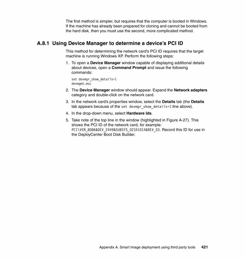
The first method is simpler, but requires that the computer is booted in Windows. If the machine has already been prepared for cloning and cannot be booted from the hard disk, then you must use the second, more complicated method.
A.8.1 Using Device Manager to determine a device’s PCI IDThis method for determining the network card’s PCI ID requires that the target machine is running Windows XP. Perform the following steps:
1. To open a Device Manager window capable of displaying additional details about devices, open a Command Prompt and issue the following commands:
set devmgr_show_details=1devmgmt.msc
2. The Device Manager window should appear. Expand the Network adapters category and double-click on the network card.
3. In the network card’s properties window, select the Details tab (the Details tab appears because of the set devmgr_show_details=1 line above).
4. In the drop-down menu, select Hardware Ids.
5. Take note of the top line in the window (highlighted in Figure A-27). This shows the PCI ID of the network card, for example: PCI\VEN_8086&DEV_2449&SUBSYS_02341014&REV_03. Record this ID for use in the DeployCenter Boot Disk Builder.
Appendix A. Smart Image deployment using third party tools 421
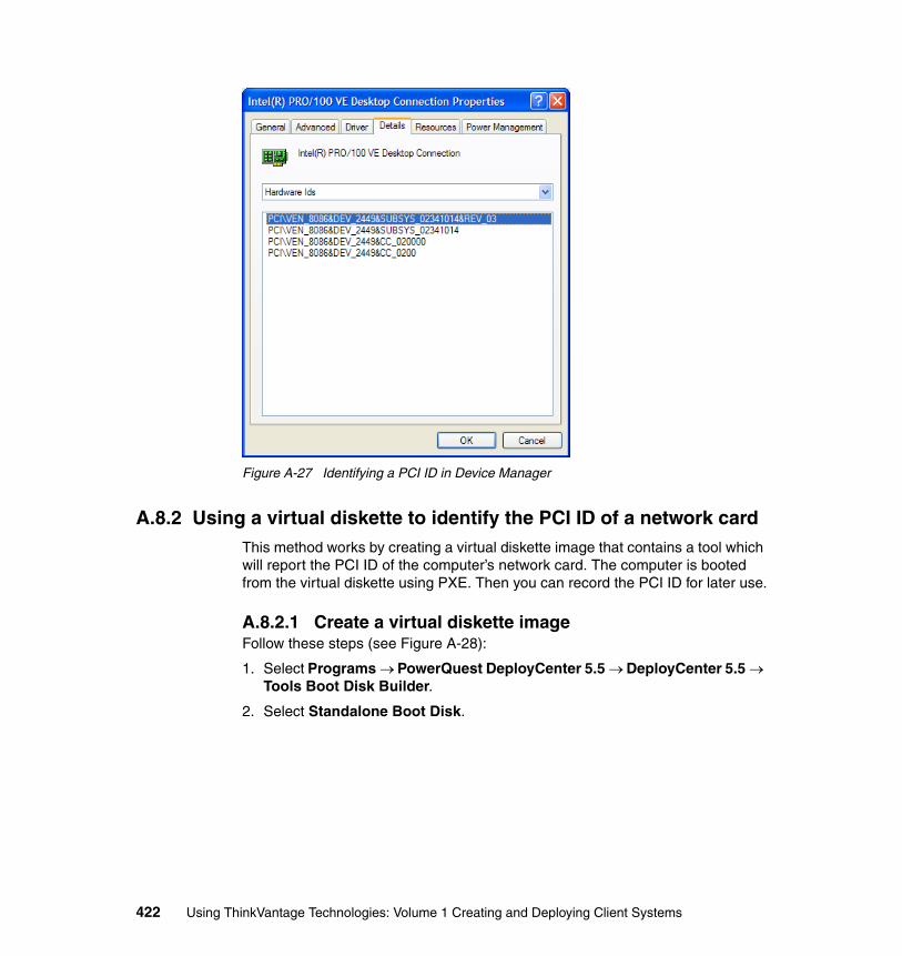
Figure A-27 Identifying a PCI ID in Device Manager
A.8.2 Using a virtual diskette to identify the PCI ID of a network cardThis method works by creating a virtual diskette image that contains a tool which will report the PCI ID of the computer’s network card. The computer is booted from the virtual diskette using PXE. Then you can record the PCI ID for later use.
A.8.2.1 Create a virtual diskette imageFollow these steps (see Figure A-28):
1. Select Programs → PowerQuest DeployCenter 5.5 → DeployCenter 5.5 → Tools Boot Disk Builder.
2. Select Standalone Boot Disk.
422 Using ThinkVantage Technologies: Volume 1 Creating and Deploying Client Systems
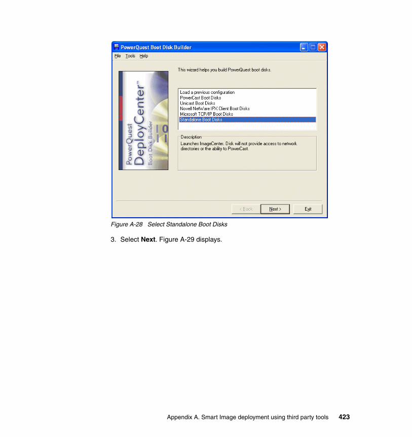
Figure A-28 Select Standalone Boot Disks
3. Select Next. Figure A-29 displays.
Appendix A. Smart Image deployment using third party tools 423
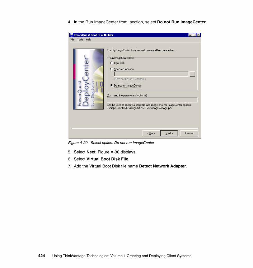
4. In the Run ImageCenter from: section, select Do not Run ImageCenter.
Figure A-29 Select option: Do not run ImageCenter
5. Select Next. Figure A-30 displays.
6. Select Virtual Boot Disk File.
7. Add the Virtual Boot Disk file name Detect Network Adapter.
424 Using ThinkVantage Technologies: Volume 1 Creating and Deploying Client Systems
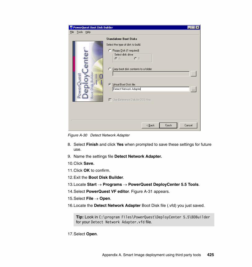
Figure A-30 Detect Network Adapter
8. Select Finish and click Yes when prompted to save these settings for future use.
9. Name the settings file Detect Network Adapter.
10.Click Save.
11.Click OK to confirm.
12.Exit the Boot Disk Builder.
13.Locate Start → Programs → PowerQuest DeployCenter 5.5 Tools.
14.Select PowerQuest VF editor. Figure A-31 appears.
15.Select File → Open.
16.Locate the Detect Network Adapter Boot Disk file (.vfd) you just saved.
17.Select Open.
Tip: Look in C:\program Files\PowerQuest\DeployCenter 5.5\BDBuilder for your Detect Network Adapter.vfd file.
Appendix A. Smart Image deployment using third party tools 425
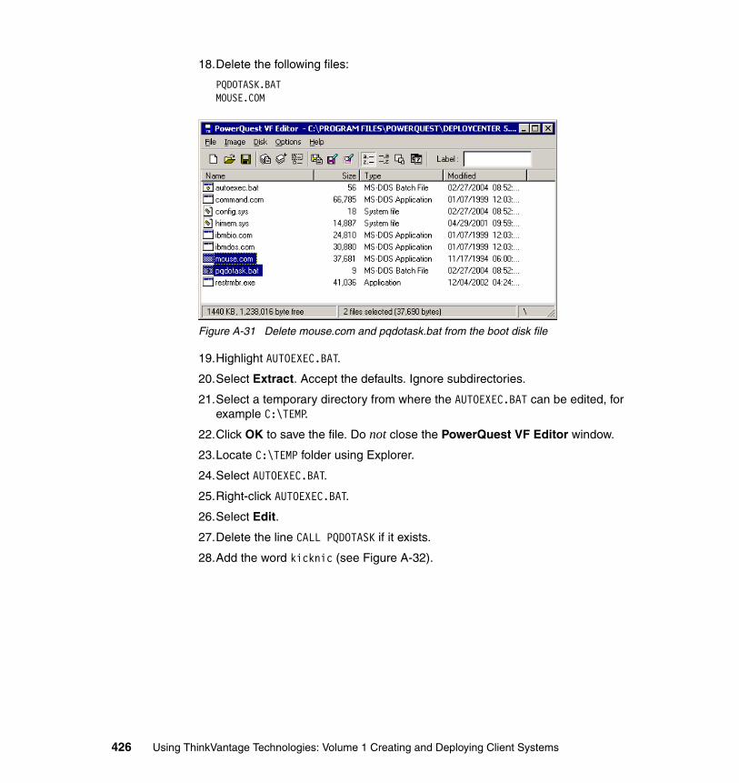
18.Delete the following files:
PQDOTASK.BATMOUSE.COM
Figure A-31 Delete mouse.com and pqdotask.bat from the boot disk file
19.Highlight AUTOEXEC.BAT.
20.Select Extract. Accept the defaults. Ignore subdirectories.
21.Select a temporary directory from where the AUTOEXEC.BAT can be edited, for example C:\TEMP.
22.Click OK to save the file. Do not close the PowerQuest VF Editor window.
23.Locate C:\TEMP folder using Explorer.
24.Select AUTOEXEC.BAT.
25.Right-click AUTOEXEC.BAT.
26.Select Edit.
27.Delete the line CALL PQDOTASK if it exists.
28.Add the word kicknic (see Figure A-32).
426 Using ThinkVantage Technologies: Volume 1 Creating and Deploying Client Systems
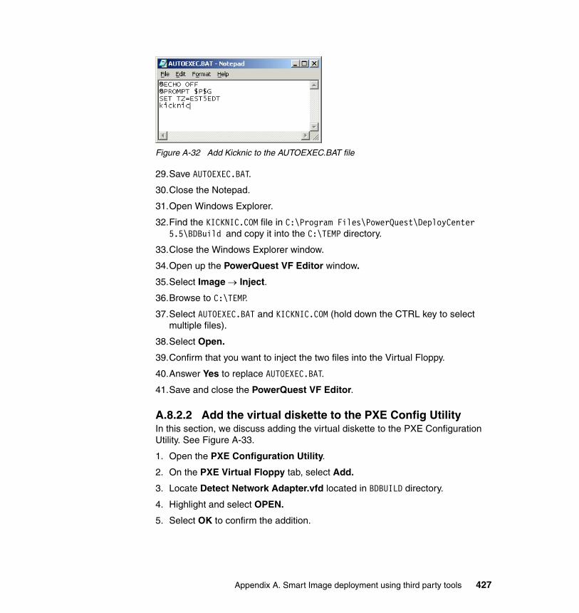
Figure A-32 Add Kicknic to the AUTOEXEC.BAT file
29.Save AUTOEXEC.BAT.
30.Close the Notepad.
31.Open Windows Explorer.
32.Find the KICKNIC.COM file in C:\Program Files\PowerQuest\DeployCenter 5.5\BDBuild and copy it into the C:\TEMP directory.
33.Close the Windows Explorer window.
34.Open up the PowerQuest VF Editor window.
35.Select Image → Inject.
36.Browse to C:\TEMP.
37.Select AUTOEXEC.BAT and KICKNIC.COM (hold down the CTRL key to select multiple files).
38.Select Open.
39.Confirm that you want to inject the two files into the Virtual Floppy.
40.Answer Yes to replace AUTOEXEC.BAT.
41.Save and close the PowerQuest VF Editor.
A.8.2.2 Add the virtual diskette to the PXE Config UtilityIn this section, we discuss adding the virtual diskette to the PXE Configuration Utility. See Figure A-33.
1. Open the PXE Configuration Utility.
2. On the PXE Virtual Floppy tab, select Add.
3. Locate Detect Network Adapter.vfd located in BDBUILD directory.
4. Highlight and select OPEN.
5. Select OK to confirm the addition.
Appendix A. Smart Image deployment using third party tools 427
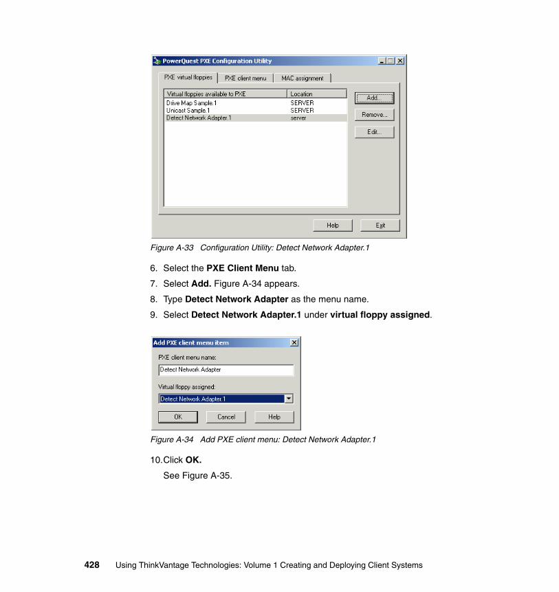
Figure A-33 Configuration Utility: Detect Network Adapter.1
6. Select the PXE Client Menu tab.
7. Select Add. Figure A-34 appears.
8. Type Detect Network Adapter as the menu name.
9. Select Detect Network Adapter.1 under virtual floppy assigned.
Figure A-34 Add PXE client menu: Detect Network Adapter.1
10.Click OK.
See Figure A-35.
428 Using ThinkVantage Technologies: Volume 1 Creating and Deploying Client Systems
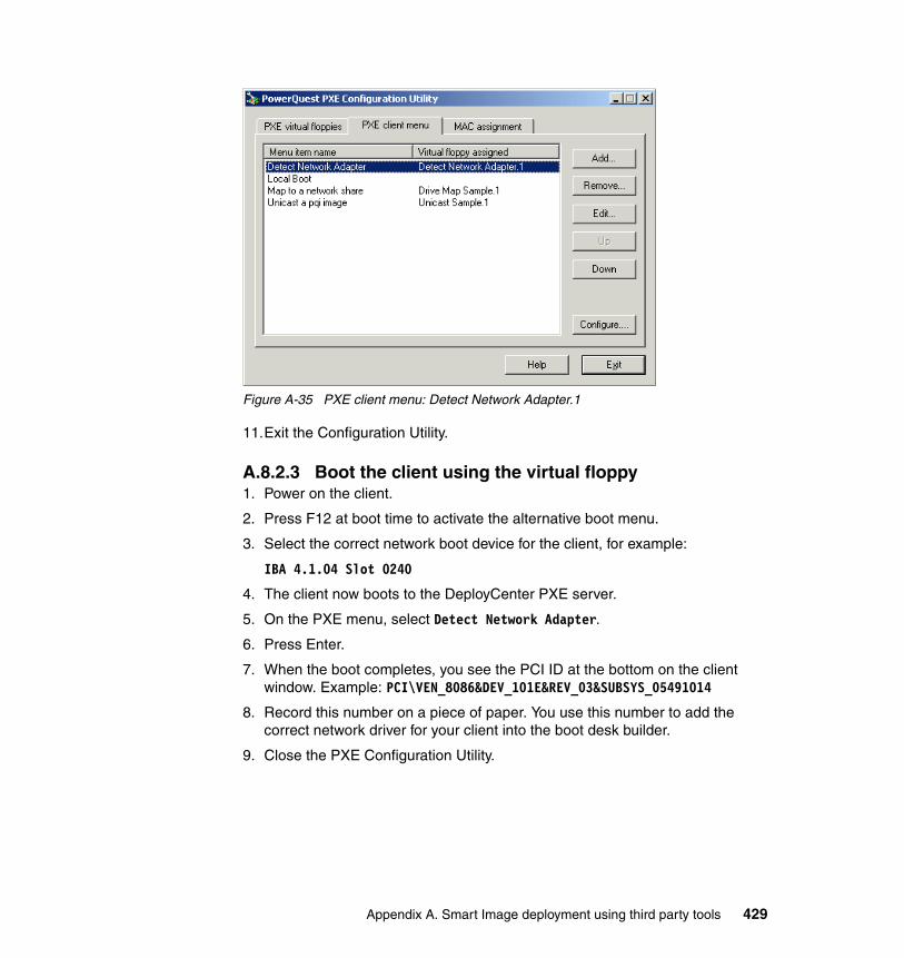
Figure A-35 PXE client menu: Detect Network Adapter.1
11.Exit the Configuration Utility.
A.8.2.3 Boot the client using the virtual floppy1. Power on the client.
2. Press F12 at boot time to activate the alternative boot menu.
3. Select the correct network boot device for the client, for example:
IBA 4.1.04 Slot 0240
4. The client now boots to the DeployCenter PXE server.
5. On the PXE menu, select Detect Network Adapter.
6. Press Enter.
7. When the boot completes, you see the PCI ID at the bottom on the client window. Example: PCI\VEN_8086&DEV_101E&REV_03&SUBSYS_05491014
8. Record this number on a piece of paper. You use this number to add the correct network driver for your client into the boot desk builder.
9. Close the PXE Configuration Utility.
Appendix A. Smart Image deployment using third party tools 429

430 Using ThinkVantage Technologies: Volume 1 Creating and Deploying Client Systems
acronyms
ACPI Advanced Configuration and Power Interface
AES Advanced Encryption Standard
API application programming interface
APS Active Protection System
ATAPI AT Attachment with Packet Interface
BINL Binary Information Negotiation Layer
BIOS Basic Input/Output System
BM boot manager
BMGR boot manager
BSOD blue screen STOP condition
CAD CTRL+ALT+DEL
CD compact disc
CD-R compact disc - recordable
CD-R/RW compact disc - recordable/rewritable
CD-ROM compact-disc read-only memory
CHAP Challenge Handshake Authentication Protocol
CLS Continuous Linked Settlement
CMD command
CPU central processing unit
CSS Client Security Software
DB database
DHCP Dynamic Host Configuration Protocol
DLL dynamic link library
DNS Domain Name System
DOE Dynamic Operating Environment
DOS disk operating system
DSL device (Digital Subscriber Line)
DVD digital video disc
DVD+R/RW DVD + recordable/rewritable
DVD-ROM DVD read only memory
Abbreviations and
© Copyright IBM Corp. 2005. All rights reserved.
DWORD double word
EAP Extensible Authentication Protocol
EAP-TLS EAP Transport Layer Security
EAP-TTLS EAP tunneled TLS
EEPROM Electrically Erasable Programmable Read-Only Memory
ESS Embedded Security Subsystem
FAQ frequently asked question
FAR False Acceptance Rate
FAT file allocation table
FDISK format disk
FFE files and folders Encryption
FN function
FTP File Transfer Protocol
GB gigabyte
GINA Graphic Identification and Authentication
GTC generic token card
GUI graphical user interface
HAL Hardware Abstraction Layer
HDD hard disk drive
HIIT Hardware Independent Imaging Technology
HPA Hidden Protected Area
HSI Hardware Specific Image
HTML Hypertext Markup Language
HTTP Hypertext Transfer Protocol
I/O input/output
IBM International Business Machines Corporation
ID identifier
IDE Integrated Drive Electronics
IDE/ATA IDE/At Attachment
431
IE Internet Explorer
IFS Installable File System
IN intelligent network
IP Internet Protocol
IPX Internet Packet Exchange
ISDN Integrated Services Digital Network
ISIC IBM System Information Center
ISO International Organization for Standardization
ISP Internet service provider
IT Information Technology
ITC Image Technology Center
ITSO International Technical Support Organization
IU installable unit
IUB ImageUltra Builder
IUBCP IUB Customization Program
JDBC™ Java Database Connectivity
JNDI Java Naming and Directory Interface™
JRE Java Runtime Environment
KB kilobyte
LAN local area network
LDAP Lightweight Directory Access Protocol
LEAP Lightweight Extensible Application Protocol
LEAP-TKIP LEAP Temporal Key Integrity Protocol
LPC Low Pin count
MAC Medium Access Control
MB megabyte
MBR Master Boot Record
MFD Multiple File Download
MSCAPI Microsoft Crypto API
MSI Microsoft InstallShield package
MSN message sequence number
MTM machine type model
NDIS Network Device/Driver Interface Specification
NT network termination
NTFS One of the native file systems in the Windows NT and later operating environments such as Windows 2000
NTLM NT LAN Manager
ODBC Open Database Connectivity
OEM original equipment manufacturer
OPSEC open platform for security
OS operating system
PARTIES Protected Area Runtime Interface Extension Services
PBA pre-boot authentication
PCI Peripheral Component Interconnect
PDA Predesktop Environment
PDF Portable Document Format
PE Preinstallation Environment
PEAP Protected Extensible Authentication Protocol
PEAP-GTC PEAP generic token card
PID process ID
PIN personal identification number
PKI Public Key Infrastructure
POST power-on self test
PSI Portable Sysprep Image
PSK Phase Shift Keying
PTA Personal Trust Agent
PXE Pre-boot Execution Environment
RADIUS Remote Authentication Dial-In User Service
RAM random access memory
RDM Rapid Deployment Manager
REM ring error monitor
RIS Remote Installation Services
ROI return on investment
ROM read-only memory
432 Using ThinkVantage Technologies: Volume 1 Creating and Deploying Client Systems
RSA Rivest-Shamir-Adleman algorithm
RTP Real-Time Transport Protocol
SAL Secure Automatic Logon
SATA serial ATA
SCSI Small Computer System Interface
SDA Software Delivery Assistant
SDC Software Delivery Center
SDD Secure Data Disposal
SET Secure Electronic Transaction
SGE SafeGuard Easy
SID source ID
SIS Single Instance Storage
SLP System Locked Preinstallation
SMA System Migration Assistant
SMB small and medium-sized business
SMS Short Message Service storage management subsystem
SP service partition
SQL Structured Query Language
SSID subsystem identifier
SSO single signon
STDOUT standard output
TAM Tivoli Access Manager
TCG Trusted Computing Group
TCO total cost of ownership
TCP Trusted Computing Platform
TCP/IP Transmission Control Protocol/Internet Protocol
TCPA Trusted Computing Platform Alliance
TI Traditional Image
TKIP Temporal Key Integrity Protocol
TLS Transport Layer Security
TME® Tivoli Management Environment®
TPM Trusted Platform Module
TSR terminate and stay resident
TTLS tunneled transport layer security
TVSU ThinkVantage System Update
TVT ThinkVantage Technologies
UC Update Connector
UCS universal character set
UI unique identifier
UNC Universal Naming Convention
UPI Ultra-Portable Image
URL Uniform Resource Locator
USB Universal Serial Bus
UUID Universal Unique Identifier
UVM User Verification Manager
VBD virtual boot disk
VBE Virtual Boot Environment
VOB versioned object base
VPN Virtual Private Networking
WAN wide area network
WEP Wired Equivalency Protocol
WLAN Wireless LAN
WPA Wireless (Wi-FI) Protected Access
WPA-PSK WPA Phase Shift Keying
WPA-TKIP WPA Temporal Key Integrity Protocol
XML Extensible Markup Language
Abbreviations and acronyms 433

434 Using ThinkVantage Technologies: Volume 1 Creating and Deploying Client Systems
Related publications
The publications listed in this section are considered particularly suitable for a more detailed discussion of the topics covered in this redbook.
IBM RedbooksFor information about ordering these publications, see “How to get IBM Redbooks” on page 437. Note that some of the documents referenced here may be available in softcopy only.
� Using ThinkVantage Technologies Volume 2: Maintaining and Recovering Client Systems, SG24-7107-00
� Using ThinkVantage Technologies Volume 2: Maintaining and Recovering Client Systems, SG24-6060-03
� Implementing Systems Management Solutions using IBM Director, SG24-6188
� ThinkVantage Technologies: Using IBM System Information Center, REDP-3954
� ThinkVantage Technologies: Using IBM Software Delivery Center, REDP-3976
� Deploying the IBM Secure Wireless Networking Solution for Cisco Systems, REDP-3958
Other publicationsThese publications are also relevant as further information sources:
� ThinkVantage Technologies Deployment Guide
http://www.ibm.com/pc/support/site.wss/document.do?lndocid=TVAN-RNRCDG
� ThinkVantage ImageUltra Builder User’s Guide
http://www.ibm.com/pc/support/site.wss/document.do?lndocid=MIGR-44628
� ThinkVantage System Migration Assistant 5.0 User’s Guide
http://wwwibm.com/pc/support/site.wss/document.do?lndocid=TVAN-SMAUG
© Copyright IBM Corp. 2005. All rights reserved. 435
� ThinkVantage Access Connections Profile Deployment Guide
http://www.ibm.com/pc/support/site.wss/document.do?lndocid=MIGR-52881
� How to set up, configure, and use Remote Installation Services in Windows 2000
http://support.microsoft.com/?kbid=891275
� How to boot the Windows Preinstall Environment from a RIS server by using PXE-enabled clients
http://support.microsoft.com/?kbid=304992
� Description of PXE Interaction Among PXE Client, DHCP, and RIS Server
http://support.microsoft.com/?kbid=244036
Online resourcesThese Web sites are also relevant as further information sources:
� Lenovo Technologies ThinkVantage Technologies Overview
http://www.pc.ibm.com/us/think/thinkvantagetech.html
� ImageUltra Builder
http://www.lenovo.com/think/support/site.wss/MIGR-44316.html
� System Migration Assistant
http://www.lenovo.com/think/support/site.wss/document.do?lndocid=MIGR-50889
� System Migration Assistant User’s Guide
http://www.ibm.com/pc/support/site.wss/document.do?lndocid=TVAN-SMAUG
� Secure Data Disposal
http://www.ibm.com/pc/support/site.wss/document.do?lndocid=TVAN-SDD
� Access Connections software download
http://www.ibm.com/pc/support/site.wss/document.do?lndocid=MIGR-4ZLNJB
� Hotkey drivers
http://www.ibm.com/pc/support/site.wss/document.do?lndocid=MIGR-38953
� Access Connections Deployment feature download
http://www.ibm.com/pc/support/site.wss/document.do?lndocid=ACON-DEPLOY
� Access Connections Deployment Feature User’s Guide
http://www.ibm.com/pc/support/site.wss/document.do?lndocid=MIGR-52881
436 Using ThinkVantage Technologies: Volume 1 Creating and Deploying Client Systems
� Active Protection System software download
http://www.ibm.com/pc/support/site.wss/document.do?lndocid=MIGR-53150
� Symantec, Inc.
http://www.symantec.com
� LANDesk Management Suite 8.6 for ThinkVantage Technologies
http://www.pc.ibm.com/us/think/thinkvantagetech/landesk.html
� LANDesk Software homepage
http://www.landesk.com/
� LANDesk product trial
http://www.landesk.com/partner/lenovo/trial/
How to get IBM RedbooksYou can search for, view, or download Redbooks, Redpapers, Hints and Tips, draft publications, and Additional materials, as well as order hardcopy IBM Redbooks or CD-ROMs, at this Web site:
ibm.com/redbooks
Help from IBMIBM Support and downloads
ibm.com/support
IBM Global Services
ibm.com/services
Related publications 437

438 Using ThinkVantage Technologies: Volume 1 Creating and Deploying Client Systems
Index
Numerics11a/b/g Wirless LAN Mini PCI Express Adapter 2763rd party deployment tools 373–429
Aaccelerometer 343, 345, 356Access Connections 275–342
11a/b/g Wirless LAN Mini PCI Express Adapter 276automatic program startup 293–294Bluetooth 276, 307, 313, 329, 338Cisco Systems Mini-PCI Wireless LAN Adapter 276default printer 292disable Windows’ control 317EAP-TLS 278Enabler for Administrator Profile Deployment Feature 329–341Encryption 320find wireless network 319–321Fn+F5 313, 319, 325–329global settings 312–313hardware wireless radio switch 326IBM 11a/b/g Wireless LAN Mini PCI Adapter 276IBM 11a/b/g Wireless LAN Mini PCI Adapter II 276IBM 11b/g Wireless LAN Mini PCI Adapter 276IBM Dual-Band Wi-Fi Wireless Mini-PCI Adapter 276installation 279–281
automated installation 280manual installation 280–281with wireless LAN driver pack 281–282
Intel PRO/Wireless 2200BG Network Connec-tion 276Intel PRO/Wireless 2915ABG Network Connec-tion 276location profile 282–305
detailed setup 282–299managing 314–317quick setup 299–305
location switching 308–311
© Copyright IBM Corp. 2005. All rights reserved.
MAC Address 320managing location profiles 314–317network connections
broadband 276cable modem 276Digital Subscriber Line 276Ethernet 276Integrated Services Digital Network 276Token Ring 276Virtual Private Networking 276
Network Name 320overview 4PEAP-GTC 278PEAP-MS Chap V2 278preferences 313prerequisites 277profile deployment feature 329–341profiles 282–305proxy settings 289–290RADIUS server 306security settings 290–291Service Set Identification 288, 320
defined 320Static WEP 278status window 306–308supported systems 277switching between profiles 323System Migration Assistant 195ThinkPad Z Series 326tray icon status messages 322Verizon Wireless WAN modem 276wireless devices
disable Windows’ control 317Wireless Mode 320wireless network considerations 317–321WPA 278WPA-PSK 278
ACPISee Advanced Configuration and Power Inter-face
Active Protection System 343–358accelerometer 343, 345, 356configuration 348–349design 355–357
439
heuristic learning algorithm 357motion sensor 343, 356real-time status 350–355user interface 346–347version information 351
Active Update 7Advanced Configuration and Power Interface 374always install 42application modules 21, 50–56
defined 24apply phase 192–193
defined 184APS
See Active Protection Systemauditboot 42, 101automatic program startup 293–294
Bbase map
defined 21base operating system modules
defined 23Bluetooth 276, 307, 313, 329, 338broadband 276build
defined 21
Ccable modem 276Call Center Employee 272capture phase 192–193
capturing settings and files 193–220defined 184
Cisco Systems Mini-PCI Wireless LAN Adapter 276Client Security Software
overview 6Client Security Solution
overview 6command file
behavior during apply phase 239creating a template 226–228customizing 228–240GUI_default_commands.xml 222, 228, 243, 254parameters 228–234
commands.xmldefined 183
config.ini
customizing 220–226defined 183
containerdefined 21
custom migration 193defined 192
custom modules 47–50
Ddefault printer 292Department of Defense-compliant 269, 271deploy
CD-ROM / DVD deployment 146–151defined 21, 144deployment environment 146deployment troubleshooting 166–168ISO image 169–170memory key deployment 163–166network deployment 152–162process overview 144–145USB deployment 163–166using 3rd party tools 373–429using Symantec DeployCenter 405–419
DEPLOY2.PY 164DeployCenter
See Symantec DeployCenterdevice driver modules 56–65
defined 24install using INF 63install using setup.exe 56
Digital Subscriber Line 276DOE
See Dynamic Operating EnvironmentDrive Image
See PowerQuest Drive Imagedriver map 21, 42
defined 21DSL
See Digital Subscriber LineDynamic Operating Environment
defined 22
EEAP-TLS 278Embedded Security Subsystem
overview 6Enabler for Administrator Profile Deployment Fea-ture 329–341
440 Using ThinkVantage Technologies: Volume 1 Creating and Deploying Client Systems
end-of-life disposition 1Ethernet 276
Ffilter
defined 22, 41find wireless network 319–321fingerprint reader
overview 6first boot 42Fn+F5 313, 319
Access Connections 325–329
GGhost
See Symantec Ghostgold module
defined 22Groveler Service 379GUI_default_commands.xml 222, 228, 243, 254
HHAL
See Hardware Abstraction LayerHardware Abstraction Layer 18, 68–69, 100, 374Hardware Independent Imaging Technology 42, 360
defined 22enabled 24
hardware wireless radio switch 326Hardware-Specific Image 78–99
creating a seed system 78defined 22, 68Symantec DeployCenter 387Symantec Ghost 382using a Traditional Image 80
Hidden Protected Area 23defined 23
HPASee Hidden Protected Area
HR Employee 272HSI
See Hardware-Specific Image
IIBM 11a/b/g Wireless LAN Mini PCI Adapter 276IBM 11a/b/g Wireless LAN Mini PCI Adapter II 276
IBM 11b/g Wireless LAN Mini PCI Adapter 276IBM Director 7IBM Dual-Band Wi-Fi Wireless Mini-PCI Adapter 276IBM Update Connector 7ignore HIIT processing 42image
complexity 18defined 15management 18
image typesHardware-Specific Image 78–99
defined 22, 68Portable-Sysprep Image 99–123
defined 24, 68Traditional Image
defined 25, 68Ultra-Portable Image 123–143
defined 26, 69ImageCenter
See Symantec DeployCenter ImageCenterimage-cloning tool 24ImageUltra Builder 13–177, 369
application modules 50–56defined 24
auditboot 42base map
defined 21base operating system modules
defined 23basic operation 19behavior 41build
defined 21components 19container
defined 21custom modules 47–50deploy
CD-ROM / DVD deployment 146–151defined 21, 144deployment environment 146deployment troubleshooting 166–168ISO image 169–170memory key deployment 163–166network deployment 152–162process overview 144–145USB deployment 163–166using 3rd party tools 373–429
Index 441
using Symantec DeployCenter 405–419DEPLOY2.PY 164device driver modules 56–65
defined 24install using INF 63install using setup.exe 56
driver mapdefined 21
Dynamic Operating Environmentdefined 22
filterdefined 22, 41
first boot 42gold module
defined 22Hardware Independent Imaging Technology 42
defined 22enabled 24
Hardware-Specific Image 78–99creating a seed system 78Symantec DeployCenter 387Symantec Ghost 382using a Traditional Image 80
Hidden Protected Areadefined 23
imagecomplexity 18defined 15management 18
image typesHardware-Specific Image 78–99
creating a seed system 78defined 22, 68using aTraditional Image 80
Portable-Sysprep Image 99–123creating a seed system 100defined 24, 68using aTraditional Image 102
Traditional Imagedefined 25, 68
Ultra-Portable Image 123–143defined 26, 69
import preload modules 66INF installable 42INF relative location 42install slot 42installation 27–29InstallShield 48LANDesk 175–177
mapdefined 17
modulesapplication 21, 24base operating system 23defined 17, 23device driver 24import preload 66operating system add-on 23partitioning 21, 23provided with IUB 43–46
network deployment 152–162network deployment CD, creating 152–157network sync 146
defined 24operating system add-on modules
defined 23overview 3partitioning modules
defined 23Portable-Sysprep Image 99–123
creating a seed system 100Symantec DeployCenter 387Symantec Ghost 382using a Traditional Image 102
repositoryadministration 29–36creating 30–34defined 17, 21, 25deleting 34–35import 30, 77preparing for Smart Image 73–78production 30, 77test 30, 77
scenario with Symantec DeployCenter 388–405service partition 15, 21, 23–24, 30, 36, 44, 77, 122, 142–143
defined 25importing modules from 66
silent install command 41silent installation
defined 47Smart Image
defined 17, 25Smart Image types
defined and compared 67–73suported operating systems 26sysprep 18, 68, 78–79, 100, 122, 176
442 Using ThinkVantage Technologies: Volume 1 Creating and Deploying Client Systems
limitations 374–375System Migration Assistant 174, 257target location 41terminology 21Ultra-Portable Image 123–143unattended installation
defined 47user administration 37–39utility
defined 25Windows Installer 47Windows PE
accessing the command line 419adding mass storage drivers 172adding network device drivers 172customization 170–173customize the wallpaper 171overview 146Remote Installation Services 376removing the "Press any key" prompt 171
ImageUltra Map Debugger 118imaging 10INF installable 42INF relative location 42install slot 42InstallShield 48integrated security chip 6Integrated Services Digital Network 276Intel PRO/Wireless 2200BG Network Connection 276Intel PRO/Wireless 2915ABG Network Connection 276ISDN
See Integrated Services Digital NetworkIUB Customization Program 69, 100, 102IUBCP
See IUB Customization Program
LLANDesk
ImageUltra Builder 175–177Secure Data Disposal 272–273System Migration Assistant 257–261
Mmap
defined 17memory key deployment 163–166
menu driven area 21migration
apply phase 192–193defined 184
capture phase 192–193capturing settings and files 193–220defined 184
when is it required? 181migration commands 234–237
examples 238exclude drives 234file and folder exclusions 236file and folder inclusions 235files and folders 234
migration typescustom 193
defined 192standard
customizing 220–226defined 191
target initiateddefined 191
typical 192defined 191
modulesapplication 50–56base operating system 23custom 47–50defined 17, 23device driver 24, 56–65
install using INF 63install using setup.exe 56
import preload 66operating system add-on 23partitioning 21, 23provided with ImageUltra Builder 43–46
motion sensor 343, 356msiexec.exe 47
NNetwork Boot 386network deployment 152–162network deployment CD, creating 152–157network infrastructure 4Network Name 320network sync 146
defined 24normal device detection 42
Index 443
Norton GhostSee Symantec Ghost
Ooperating system add-on modules
defined 23
PPARTIES
See Protected Area Runtime Interface Exten-sion Services
partitioning modulesdefined 23ImageUltra Builder 21
PC life cycle 1, 8, 263PCI ID 420–429
determine using Device Manager 421–422determine using virtual diskette 422–429
PEAP-GTC 278PEAP-MS Chap-V2 278Portable-Sysprep Image 78, 99–123
creating a seed system 100defined 24, 68Symantec DeployCenter 387Symantec Ghost 382using a Traditional Image 102
PowerCastingSee Symantec DeployCenter PowerCasting
PowerQuestDrive Image 99
Pre-boot Execution Environment 375, 427Remote Installation Services 375–381Symantec DeployCenter 386, 389
Productivity Centeroverview 5
profile deployment feature 329–341PROFILE.INI 379Protected Area Runtime Interface Extension Servic-es 23proxy settings 289–290PSI
See Portable-Sysprep ImagePXE
See Pre-boot Execution Environment
Qquick setup 299–305
RRADIUS server 306RDM
See Remote Deployment ManagerRedbooks Web site 437
Contact us xviiRemote Deployment Manager 7, 264
console 264Remote Installation Services 144, 173, 375
adding ImageUltra Builder boot CD 376–378multiple ImageUltra Builder images 378Pre-Boot Execution Environment 375–381troubleshooting 380Windows PE 376
repositoryadministration 29–36creating 30–34defined 17, 21, 25deleting 34–35import 30, 77preparing for Smart Image 73–78production 30, 77test 30, 77
Rescue and Recoveryoverview 5
return on investment (ROI) 3RIS
See Remote Installation Services
SSCRUB3 263, 270
See also Secure Data Disposaldefined 263Department of Defense-compliant 269, 271examples 269high security 268in-the-field debugging 268limited security 268Master Boot Record 268medium security 268scrub signature 268signature 268
SCRUB3.EXEcommand syntax 268performance considerations 270return codes 269security level 266–267using 267–270
444 Using ThinkVantage Technologies: Volume 1 Creating and Deploying Client Systems
SDCSee Software Delivery Center
SDDSee Secure Data Disposal
Secure Data Disposal 263See also SCRUB3Department of Defense-compliant 269, 271examples 269high security 268installation 265in-the-field debugging 268LANDesk 272–273limited security 268Master Boot Record 268medium security 268overview 4performance considerations 270Remote Deployment Manager 264scrub signature 268SCRUB3.EXE
command syntax 268using 267–270
SCRUB3.EXE.return codes 269security level 266–267signature 268system requirements
DOS tools 264program 264
viruses 263security settings 290security-aware applications 6service partition 15, 21, 23–24, 30, 36, 44, 77, 122, 142–143, 367, 369, 381
defined 25importing modules from 66
Service Set Identification 288, 320defined 320
SETUP.ISS 49–50, 175generate 49
silent install command 41silent installation 47
defined 47Single Instance Storage 379SLP
See System Locked PreinstallationSMA
See Software Migration AssistantSee System Migration Assistant
sma.exe
defined 183smabat.exe 226, 245, 247
defined 183Smart Image
defined 17, 25Smart Image types
defined and compared 67–73Hardware-Specific Image 68Portable-Sysprep Image 68Traditional Image 68Ultra-Portable Image 69
Software Delivery Center 361, 370overview 5with ImageUltra Builder 173
SoundMAX audio driverinstall using INF 63install using setup.exe 56
SSIDSee Service Set Identification
standard migrationcustomizing 220–226defined 191
Static WEP 278supported operating systems
ImageUltra Builder 26switching between profiles 323Symantec
DeployCenter 14, 23–24, 79, 88, 101, 106, 173, 176, 384–388
creating an image 386deploy an image 405–419Hardware-Specific Image 387ImageCenter 384overview 384Portable-Sysprep Image 387PowerCasting 412, 414, 419
overview 386Pre-boot Execution Environment 386, 389restoring an image 387scenario with ImageUltra Builder 388–405
Ghost 14–15, 23–24, 26, 79, 88, 99, 101, 106, 173, 176, 381–384
creating an image 382Hardware-Specific Image 382overview 381Portable-Sysprep Image 382restoring an image 382
ImageExplorer 385sysprep 18, 68, 78–79, 100, 122, 176
Index 445
limitations 374–375System Information Center 370
overview 5System Locked Preinstallation 122, 143System Migration Assistant 179
Access Connections 195administrative installation 240–245apply phase 192–193
batch mode 247defined 184
basic operations 184batch mode 245–248
apply phase 247capture phase 247
capture phase 192–193batch mode 247capturing settings and files 193–220defined 184
cmdfile 246command file
behavior during apply phase 239creating a template 226–228customizing 228–240parameters 228–234
command file templateprofile file 227
components 183commands.xml
defined 183config.ini
customizing 220–226defined 183
sma.exedefined 183
smabat.exedefined 183
GUI_default_commands.xml 222, 228, 243, 254ImageUltra Builder 257installation 185
administrative installation 240–245logdir 246migration
apply phase 192–193defined 184
capture phase 192–193defined 184
when is it required? 181migration commands 234–237
examples 238exclude drives 234file and folder exclusions 236file and folder inclusions 235files and folders 234
migration typescustom 193
defined 192standard
customizing 220–226defined 191
target initiateddefined 191
typical 192defined 191
overview 4profile file 183–184, 193, 217, 219
apply phase 184capture phase 184command file template 227
silent installation 185, 190smabat.exe 226, 245, 247smafile 246smapwd 246standard installation 185, 187–190supported application migration 203supported desktop settings 200supported operating systems 182system requirements 182tmpdir 246uninstall 191verbose logging 247Windows 98 limitation 199
System UpdateActive Update 7overview 7
Ttarget initiated migration
defined 191ThinkPad Z Series 326ThinkVantage Productivity Center
overview 5ThinkVantage System Update
See System UpdateThinkVantage Technologies 3ThinkVantage Tools 3TI
446 Using ThinkVantage Technologies: Volume 1 Creating and Deploying Client Systems
See Traditional ImageToken Ring 276Traditional Image 68
defined 25, 68tray icon status messages 322TVSU
See System Updatetxtsetup.oem 172typical migration 192
defined 191
UUltra-Portable Image 123–143
defined 26, 69unattend.txt 17, 45, 70, 125, 133–134, 137unattended installation
defined 47uninstalling System Migration Assistant 191Update Connector 7UPI
See Ultra-Portable ImageUSB deployment 163–166utility
defined 25Utimaco
Private Disk 238
VVBE
See Virtual Boot EnvironmentVerizon Wireless WAN modem 276Virtual Boot Diskette
create 397Virtual Boot Environment 385Virtual Private Networking 276viruses 263VPN
See Virtual Private Networking
WWebSphere Everyplace Connection Manager 297When is system migration required? 181Windows 2000
Access Connections 277Secure Data Disposal 263System Migration Assistant 182
Windows 95
Secure Data Disposal 263System Migration Assistant 182
Windows 98Secure Data Disposal 263System Migration Assistant 182
limitation 199Windows Installer 47Windows NT 4.0
Secure Data Disposal 263System Migration Assistant 182
Windows PEaccessing the command line 419adding mass storage drivers 172adding network device drivers 172customization 170–173customize the wallpaper 171overview 146Remote Installation Services 376removing the "Press any key" prompt 171
Windows XPAccess Connections 277Secure Data Disposal 263System Migration Assistant 182
winpeoem.sif 172WinRAR 50, 52wireless devices
disable Windows’ control 317wireless LAN driver pack 281–282Wireless Mode 320wireless network considerations 317–321WPA 278WPA-PSK 278
Index 447

448 Using ThinkVantage Technologies: Volume 1 Creating and Deploying Client Systems

(0.5” spine)0.475”<
->0.875”
250 <->
459 pages
Using ThinkVantage Technologies: Volume 1 Creating and Deploying Client System
s


®
SG24-7106-00 ISBN 0738494410
INTERNATIONAL TECHNICALSUPPORTORGANIZATION
BUILDING TECHNICALINFORMATION BASED ONPRACTICAL EXPERIENCE
IBM Redbooks are developed by the IBM International Technical Support Organization. Experts from IBM, Customers and Partners from around the world create timely technical information based on realistic scenarios. Specific recommendations are provided to help you implement IT solutions more effectively in your environment.
For more information:ibm.com/redbooks
Using ThinkVantage Technologies:Volume 1 Creating andDeploying Client SystemsSimplification of the PC life cycle process with ThinkVantage Technologies
Simple deployment of complex corporate environments
Use of the technologies to lower costs
ThinkVantage Technologies bring your PCs one step closer to being self-configured, self-optimizing, self-protecting, or self-healing, to help save you time and money throughout the life of your systems. In short, ThinkVantage Technologies let you focus your attention on your business, rather than on your computer.ThinkVantage Technologies are software tools designed to help customers drive down IT support costs (in particular, the cost of a PC in managing and supporting systems after its initial purchase), increase security, and decrease the complexity of today’s IT infrastructure.This IBM Redbook will help you install, tailor, and configure the ThinkVantage Technologies on Lenovo/IBM and third party desktops and mobiles.ThinkVantage Technologies covered in the book include:- ImageUltra Builder V3.0- System Migration Assistant V5.0- Secure Data Disposal V1.3- Access Connections V3.81- Active Protection System V1.33bThis is Volume 1 of a two-volume set of ThinkVantage Technologies Redbooks. It describes how to create and deploy client systems. The second volume is Using ThinkVantage Technologies Volume 2: Maintaining and Recovering Client Systems, SG24-7107.
Back cover


![ThinkVantage Access Connections 4.1: 使用手冊ps-2.kev009.com/pccbbs/mobiles_pdf/ac41ugtc.pdf · ® ú ThinkVantage Access Connections 4.1 ÷ΩTC [c 1 1 , yAccess Connections z]tAccess](https://img.pdfslide.net/doc/110x75/5ab60aa07f8b9a1a048d6f4d/thinkvantage-access-connections-41-ps-2-thinkvantage-access-connections.jpg)