Embed Size (px)
Citation preview

Using Trusted Computing to Secure Mobile
Ubiquitous Environments
Adrian Leung, Po-Wah Yau and Chris J. Mitchell
Information Security GroupRoyal Holloway, University of London
Egham, Surrey TW20 0EX, UK{A.Leung,P.Yau,C.Mitchell}@rhul.ac.uk
1 Introduction
Today’s users typically have a multitude of electronic devices, such as desktopand laptop computers, Personal Digital Assistants (PDAs) and mobile/cellularphones, each with the capability to communicate with one another. At thesame time, wireless communication has become more affordable and pervasive,and we have seen the introduction of smaller wireless-enabled devices such asheadsets and headphones. In the future, the widespread use of sensor devicesfor a variety of monitoring applications is expected to become commonplace.
A set of user devices is likely to use a range of, possibly incompatible, com-munication technologies, such as IEEE 802.3 (Ethernet), IEEE 802.11 (WLAN),Bluetooth and infrared. Regardless of the available communication methods,users and service providers will both require global Internet connectivity.
Managing such a heterogenous environment is a complex problem, and cur-rent services are singular in nature — a service is provided to a single user,and typically to only one device. The synergy of user devices is not utilisedin any way, which means additional management effort for the user. However,as user devices become more capable, at least in terms of communication andcomputation, new approaches are needed.
The Mobile Virtual Centre of Excellence (Mobile VCE)1 has been conduct-ing research aimed at such future technologies, with the goal of developing novelmeans of providing future mobile services. The underlying goal is to help deliverubiquitous services, by providing technology that enables content and serviceproviders to support multimedia applications over a range of access networktechnologies (including ad hoc networks), each with its own capabilities for ser-vice delivery. To further enhance user experience, and to reduce the complexityfor users, a new model for personal distributed computing, called a ‘Personal
1See www.mobilevce.com.
1

Distributed Environment’ (PDE) [2, 15], has been proposed. A PDE is a ‘virtualnetwork’ of a user’s devices, providing the tools to assist the user to managetheir PDE.
Inevitably, in this new environment users are vulnerable to a variety of secu-rity threats and attacks. In order to fully realise the Mobile VCE vision, soundsecurity solutions are crucial for the widespread adoption of PDE-based ubiq-uitous services. Users are becoming increasingly concerned about their onlineprivacy [6, 7], and the potential risks (such as identity theft) of leaving any formof digital trail when making electronic transactions. Given a choice, users mayprefer to remain anonymous when interacting with other entities.
Trusted Computing (TC)2 offers a range of security functionality that canbe used to help meet the objective of enhancing the security of future mobileubiquitous environments. Trusted computing is a technology that has beendeveloped to improve the security of computing platforms in increasingly het-erogenous environments. This objective is realised through the incorporationof a hardware component, known as a Trusted Platform Module (TPM), intocomputing platforms. The TPM provides the ‘trusted platform’ with a foun-dation of trust (so-called ‘roots of trust’) as well as the basis on which a suiteof TC security functionality can be built. As a result, users can gain greaterassurance that the platform with which they are interacting is behaving in theexpected manner [3, 45].
In this chapter, we show how trusted computing mechanisms can be usedto develop services to enhance the security of a PDE, to secure the process ofservice discovery in a mobile ubiquitous environment, and to support anonymouswatermarking for content distribution protection. While this chapter presentssolutions that use trusted computing technology in the context of a PDE, thegeneral approaches we present are likely to be of use in a more general context,such as in peer-to-peer networks [4, 5] to address the problem of Sybil Attacks.
The remainder of this chapter is organised as follows. Section 2 describes theubiquitous environment, provides more details about the PDE architecture, anddescribes the processes involved in the provision of ubiquitous services. Section 3contains an overview of trusted computing and the security functionality that isapplied later in this chapter. Section 4 provides an overview of the security issuessurrounding the use and provision of PDEs. Section 5 addresses the problem ofsecuring service discovery, and section 6 considers anonymous watermarking forcontent distribution detection. Finally, in section 7 we provide some concludingremarks.
2 The Mobile Ubiquitous Environment
The Mobile VCE vision of future mobile ubiquitous computing has the followingcharacteristics:
2See www.trustedcomputinggroup.org for further details, including the Trusted ComputingGroup specifications.
2

• users own multiple devices of varying capabilities,
• users (and their devices) are highly mobile, and
• users communicate using a variety of different wireless network accesstechnologies.
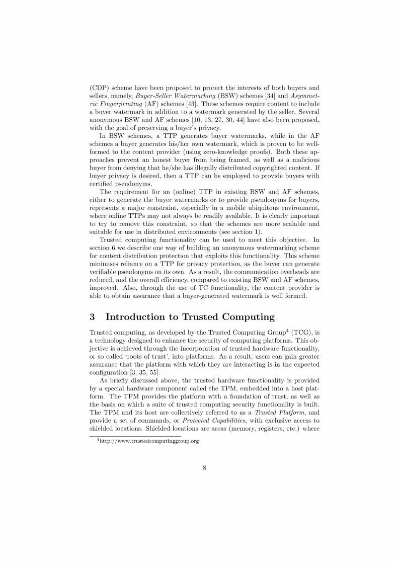
This leads to an environment of the type shown in Figure 1. Such an envi-ronment has three fundamental components — users, network technology, andservice providers.
Figure 1: A mobile ubiquitous computing environment
The diversity of network technology will help to realise the Mobile VCE vi-sion of ubiquitous computing, although addressing this heterogeneity is beyondthe scope of this chapter. Instead, we focus on the two end-parties, users and ser-vice providers, and introduce the key concepts underpinning this environment.In the ongoing Mobile VCE Core 4 programme of research into Ubiquitous Ser-vices3, it is envisaged that users will be able to seamlessly discover and access arich offering of services and content, from a wide choice of service and contentproviders, via their mobile devices; any necessary switching between networktechnologies should be transparent to the user.
As discussed above, Mobile VCE has developed a model encompassing auser’s diverse range of communication devices, called the ‘Personal DistributedEnvironment’ [2, 15]. In section 2.1, we introduce the key concepts of a PDE.A PDE will assist in the delivery of new ubiquitous services, central to thesenew dynamic environments. In section 2.2, we examine two key issues surround-ing the provision of these ‘anywhere-anytime’ services — service discovery andcontent distribution protection.
2.1 Personal Distributed Environments
A PDE is an overlay networking concept that allows a user to form a ‘virtualnetwork’ consisting of the networked devices that the user owns, or is autho-
3See www.mobilevce.com.
3

rised to use. The capabilities of these devices will typically vary in terms ofcomputational power, energy source, mobility, communication and network in-terfaces, and may reside in different physical locations. Other related overlayarchitectures, similar to the PDE concept, include those described in [36, 39, 40].
2.1.1 PDE scenario
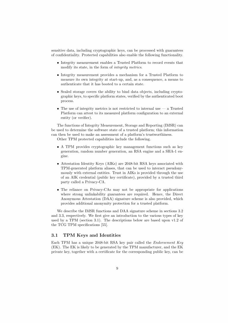
Figure 2 illustrates an example of a PDE consisting of devices that the userowns, ‘home devices’, and also third-party devices that the user may or maynot have pre-established rights to access — these are called ‘foreign devices’ inPDE terminology.
The shaded ovals represent the user’s subnetworks, and the ovalswith dashed outlines show foreign devices that are connected to theuser’s PDE.
Figure 2: A Personal Distributed Environment
For example, a user may have a home network consisting of a desktop com-puter, a printer and an ADSL connection for Internet access. Also at homemight be the user’s digital set-top box and satellite receiver used to receive dig-ital broadcasts. At work, the user might also have a desktop computer that is
4

connected to the corporate network, allowing access to foreign devices such ascorporate servers, applications, etc., that the user is authorised to access anduse, possibly remotely.
In addition to the home and work environments, a user may also have a num-ber of mobile environments. The user’s car may have an intelligent networkingcapability enabling it to retrieve satellite navigation data and traffic news viasatellite or ad hoc network communications. A user may also carry smaller de-vices, such as a mobile phone, PDA, and a laptop — these home devices cancommunicate to form a Personal Area Network (PAN). It is further envisagedthat additional foreign devices may connect to the PAN on an ad hoc basis.These could, for example, include a display monitor on a train, allowing a userto view content on a larger screen, a printer in an airport lounge, or perhaps thedevices of another user’s PDE used to transfer data or play computer games.
This example illustrates how heterogenous networks and devices can be inte-grated to form a PDE. While this results in additional complexity, the diversityof technologies can be used to deliver ubiquitous services to the user, where themost capable devices and communications means available are selected.
2.1.2 PDE management
Given the potential complexity of a PDE, there must be a way for a user tomanage a PDE in a simple and intuitive way. This is achieved through a semi-distributed construct called the Device Management Entity (DME). The pri-mary task for the DME is to intelligently select the most appropriate devicefor service delivery, acting as a Session Initiation Protocol (SIP) [46] proxy toredirect session setup requests. In order to perform this task, the DME requiresthe following functional components:
• Equipment register,
• Location register, and
• Security register.
The equipment register records and stores the capabilities of devices as theyare initialised and registered with the PDE. The location register maintainsthe location of each PDE device. The security registry stores information anddata used to support PDE security functionality — this is discussed further insection 4.
As stated previously, a user’s PDE may consist of a number of subnetworksin disparate locations. For reasons of efficiency and scale, DME functions aredistributed to a ‘local DME’ within each subnetwork, each reporting to a rootDME. This effectively creates a two layer management hierarchy.
It is proposed that the root DME will normally reside on the most capabledevice in a static subnetwork, such as the user’s home desktop or, perhapspreferably, an online PDE service provider that the user has subscribed to [50].Since the DME provides the features that enable a PDE, ensuring its availabilityis extremely important.
5

Within each PDE subnetwork, the most capable device is chosen as the localDME. In the case of mobile subnetworks the local DME selection process isdynamic, since one of the fundamental factors influencing capability is residualenergy. Atkinson et al. [2] have proposed a broadcast-based protocol to discoverthe local, home, DME-capable device with the most residual energy — alsoincluded in their proposal is a handover protocol to move control of the localDME between devices.
In section 4 we discuss how the security issues arising in a PDE might beaddressed using trusted computing functionality.
2.2 Ubiquitous Services
In a ubiquitous setting, as shown in Figure 1, a central user goal is to be able toseamlessly access ubiquitous services (or content) at any time, and anywhere,via a user device (in the user’s PDE). For example, a subscriber to digital sportscontent may wish to watch live, streamed action of a football game, while onthe move.
Recent advances in wireless networking technologies (such as WiFi, WiMax,Bluetooth, ZigBee, UWB), coupled with the ever increasing computation andcommunication capabilities of small form factor devices, have made such a visiona reality. These technological advances, however, have also introduced newsecurity challenges and vulnerabilities. Existing security solutions are not wellsuited to a mobile ubiquitous environment, because of the dynamic and highlymobile nature of users and their devices. Of particular concern are the following.
1. As users roam and move about, they may need to interact with other enti-ties from different administrative or security domains. To facilitate securecommunications, or to establish some form of trust between two entitieswith no prior service interactions, online access to a trusted third party(TTP) may be required (e.g. in a PKI setting). This task is particularlydifficult in a dynamic environment.
2. User devices are typically resource constrained because of their small formfactor, and thus may not be capable of performing computationally in-tensive cryptographic operations (e.g. performing public key algorithms).Lightweight solutions may need to be devised.
3. One other problem which is exacerbated by this new communicationsmedium is that of content distribution protection. The mobile ubiqui-tous environment not only allows content and service providers to reacha big pool of users and customers with greater ease, but similarly allowscontent pirates and illegal content distribution activities to flourish.
Whilst numerous security issues arise in a mobile ubiquitous environment,we focus here on two particularly important issues for service interactions be-tween users and service providers, namely secure service discovery and contentdistribution protection.
6

2.2.1 Service Discovery
O’Sullivan et al. [41] define a Service as: ‘An action performed by an entityon behalf of another and this action involves the transfer of value’. In thecontext of a mobile ubiquitous environment, examples of a service may includestreaming of digital broadcast content, online network gaming, etc. to multipleusers and their devices. Against this backdrop, Service Discovery can thus bedefined as: ‘The act or process of finding and locating such services in thenetwork environment’. Since a value (which may not always be monetary, e.g.reputation) is attached to a service, it is important that measures are taken toprotect and secure the service discovery process.
Service discovery typically takes place immediately prior to service provi-sioning. Many different service discovery mechanisms have been proposed (suchas Java Jini [53], UPnP [56], SLP [25], DEAPspace [38] and Salutation [48]),but few address the issue of security and privacy. Regardless of the type ofservice discovery mechanism employed, a typical service discovery process nor-mally involves the exchange of service messages (i.e. service advertisements andservice requests) between a service user and a service provider. These messages,if divulged to an eavesdropper, may reveal information about a service user (e.g.the type of services that a user is accessing or searching). It is therefore impor-tant that the process of service discovery be conducted in such a way that usersecurity and privacy is protected. Similarly, a service discovery scheme shouldalso protect service providers from rogue users.
In section 5, we discuss in greater detail the security issues arising fromservice discovery. We describe one way in which trusted computing function-ality can be used to protect and secure the process of service discovery whilstpreserving user privacy.
2.2.2 Content Distribution Protection
Illegal distribution of copyrighted digital content (e.g. music and movies) throughnew communications media poses a major challenge to the digital content in-dustries. The challenge for content providers is how to prevent or deter illegaldistribution of copyrighted materials, whilst embracing new opportunities (e.g.a more efficient distribution channel to reach a bigger customer pool) presentedby a mobile ubiquitous environment.
One way of deterring illegal content distribution is for the content provider toembed a unique ‘watermark’ into every piece of content. If unauthorised copiesof the content are found, then this watermark should enable the content providerto trace this copy of the content back to the original buyer. Such an approachsuffers from two problems. Firstly, an honest buyer may be wrongly accused(framed) of unauthorised distribution (e.g. if the content provider matches thewrong identity to the suspect copies of the content). Secondly, it is also possiblefor a malicious buyer to claim that an unauthorised copy was in fact leaked bythe content provider.
To address these problems, two types of content distribution protection
7
(CDP) scheme have been proposed to protect the interests of both buyers andsellers, namely, Buyer-Seller Watermarking (BSW) schemes [34] and Asymmet-ric Fingerprinting (AF) schemes [43]. These schemes require content to includea buyer watermark in addition to a watermark generated by the seller. Severalanonymous BSW and AF schemes [10, 13, 27, 30, 44] have also been proposed,with the goal of preserving a buyer’s privacy.
In BSW schemes, a TTP generates buyer watermarks, while in the AFschemes a buyer generates his/her own watermark, which is proven to be well-formed to the content provider (using zero-knowledge proofs). Both these ap-proaches prevent an honest buyer from being framed, as well as a maliciousbuyer from denying that he/she has illegally distributed copyrighted content. Ifbuyer privacy is desired, then a TTP can be employed to provide buyers withcertified pseudonyms.
The requirement for an (online) TTP in existing BSW and AF schemes,either to generate the buyer watermarks or to provide pseudonyms for buyers,represents a major constraint, especially in a mobile ubiquitous environment,where online TTPs may not always be readily available. It is clearly importantto try to remove this constraint, so that the schemes are more scalable andsuitable for use in distributed environments (see section 1).
Trusted computing functionality can be used to meet this objective. Insection 6 we describe one way of building an anonymous watermarking schemefor content distribution protection that exploits this functionality. This schememinimises reliance on a TTP for privacy protection, as the buyer can generateverifiable pseudonyms on its own. As a result, the communication overheads arereduced, and the overall efficiency, compared to existing BSW and AF schemes,improved. Also, through the use of TC functionality, the content provider isable to obtain assurance that a buyer-generated watermark is well formed.
3 Introduction to Trusted Computing
Trusted computing, as developed by the Trusted Computing Group4 (TCG), isa technology designed to enhance the security of computing platforms. This ob-jective is achieved through the incorporation of trusted hardware functionality,or so called ‘roots of trust’, into platforms. As a result, users can gain greaterassurance that the platform with which they are interacting is in the expectedconfiguration [3, 35, 55].
As briefly discussed above, the trusted hardware functionality is providedby a special hardware component called the TPM, embedded into a host plat-form. The TPM provides the platform with a foundation of trust, as well asthe basis on which a suite of trusted computing security functionality is built.The TPM and its host are collectively referred to as a Trusted Platform, andprovide a set of commands, or Protected Capabilities, with exclusive access toshielded locations. Shielded locations are areas (memory, registers, etc.) where
4http://www.trustedcomputinggroup.org
8
sensitive data, including cryptographic keys, can be processed with guaranteesof confidentiality. Protected capabilities also enable the following functionality.
• Integrity measurement enables a Trusted Platform to record events thatmodify its state, in the form of integrity metrics.
• Integrity measurement provides a mechanism for a Trusted Platform tomeasure its own integrity at start-up, and, as a consequence, a means toauthenticate that it has booted to a certain state.
• Sealed storage covers the ability to bind data objects, including crypto-graphic keys, to specific platform states, verified by the authenticated bootprocess.
• The use of integrity metrics is not restricted to internal use — a TrustedPlatform can attest to its measured platform configuration to an externalentity (or verifier).
The functions of Integrity Measurement, Storage and Reporting (IMSR) canbe used to determine the software state of a trusted platform; this informationcan then be used to make an assessment of a platform’s trustworthiness.
Other TPM protected capabilities include the following.
• A TPM provides cryptographic key management functions such as keygeneration, random number generation, an RSA engine and a SHA-1 en-gine.
• Attestation Identity Keys (AIKs) are 2048-bit RSA keys associated withTPM-generated platform aliases, that can be used to interact pseudony-mously with external entities. Trust in AIKs is provided through the useof an AIK credential (public key certificate), provided by a trusted thirdparty called a Privacy-CA.
• The reliance on Privacy-CAs may not be appropriate for applicationswhere strong unlinkability guarantees are required. Hence, the DirectAnonymous Attestation (DAA) signature scheme is also provided, whichprovides additional anonymity protection for a trusted platform.
We describe the IMSR functions and DAA signature scheme in sections 3.2and 3.3, respectively. We first give an introduction to the various types of keyused by a TPM (section 3.1). The descriptions below are based upon v1.2 ofthe TCG TPM specifications [55].
3.1 TPM Keys and Identities
Each TPM has a unique 2048-bit RSA key pair called the Endorsement Key(EK). The EK is likely to be generated by the TPM manufacturer, and the EKprivate key, together with a certificate for the corresponding public key, can be
9

used to prove that a genuine TPM is contained in a platform. However, since aTPM only has one such key pair, a TPM can be uniquely identified by its EK.
The EK is therefore only used in very special circumstances. A TPM can,however, generate an arbitrary number of 2048-bit RSA Attestation IdentityKey (AIK) key pairs, which are used for interacting with other entities. AIKsfunction as pseudonyms for a trusted platform, and platform privacy can beachieved by using a different AIK to interact with different entities. In order toprove that a particular AIK originates from a genuine TPM, a platform has toprove that the AIK public key is associated with a genuine trusted platform; thisinvolves use of the EK in an exchange with a trusted third party in such a waythat the AIK cannot be linked with a particular EK, even by the trusted thirdparty that sees the EK public key. The DAA protocol (discussed in section 3.3)is used to support this process.
3.2 Integrity Measurement, Storage and Reporting
Integrity Measurement, Storage and Reporting (IMSR) is one of the key featuresof trusted computing. IMSR builds upon the three ‘roots of trust’ in a trustedplatform, namely, the root of trust for measurement (RTM), the root of trust forstorage (RTS), and the root of trust for reporting (RTR). Together, they allowa verifier to learn the exact operational state of a platform, and hence obtainevidence of a platform’s behaviour. This functionality is extremely importantas a platform may potentially enter one of a wide range of operational states,including those that are insecure and undesirable.
3.2.1 Integrity Measurement
IMSR begins with the process of integrity measurement. The RTM, a computingengine in the TPM, measures the platform’s operational state and character-istics. The measured values, known as integrity metrics, convey informationabout the platform’s current state (and hence trustworthiness).
3.2.2 Integrity Storage
Details of exactly which measurements have been performed are stored in afile called the Stored Measurement Log (SML). Using the RTS, a digest (i.e.a cryptographic hash computed using Secure Hash Algorithm 1 (SHA-1) [37])of the integrity metrics is saved in one of the TPM’s internal registers, calledPlatform Configuration Registers (PCRs).
The SML contains the sequence of all measured events, and each sequenceshares a common measurement digest. Since an SML may become fairly large,it does not reside in the TPM. Integrity protection for the SML is not nec-essary, since it functions as a means to interpret the integrity measurementsin the PCRs, and any modifications to the SML will cause subsequent PCRverifications to fail.
10

There are only a limited number of PCRs in the TPM to hold the mea-surement digests. So, in order to ensure that previous and related measuredvalues are not ignored/discarded, and the order of operations is preserved, newmeasurements are appended to a previous measurement digest, re-hashed, andthen put back into the relevant PCR. This technique is known as extending thedigest, and operates as follows:
PCRi [n] ← SHA-1 (PCRi−1 [n] ||New integrity metric),
where PCRi[n] denotes the content of the nth PCR after i extension operations,and || denotes the bit string concatenation operator.
The processes of integrity measuring and storage can be used by a trustedplatform to authenticate its boot process — at each stage of the boot processa measurement is taken of the components required for the subsequent stage,before control is passed to those measured components [24] (see Figure 3).
Figure 3: An example of an authenticated boot process
3.2.3 Integrity Reporting
The final phase of the IMSR process is Integrity Reporting. The RTR has twomain responsibilities during Integrity Reporting:
1. to retrieve and provide a challenger with the requested integrity metrics(i.e. the relevant portion of the SML, and the corresponding PCR values);and
2. to attest to (prove) the authenticity of the integrity metrics to a challengerby signing the PCR values using one of the TPM’s AIK private keys.
To verify the integrity measurements, the verifier computes the measurementdigest (using the relevant portion of the SML), compares it with the correspond-ing PCR values, and checks the signature on the PCR values. The process ofintegrity reporting is also often referred to as Attestation.
11
3.3 Direct Anonymous Attestation
Direct Anonymous Attestation (DAA) [8, 9] is a special type of signature schemethat can be used to anonymously authenticate a TCG v1.2 compliant platformto a remote verifier. The key feature that DAA provides is the capability for aTPM (a prover) to convince a remote verifier that:
• it is indeed a genuine TPM (and hence it will behave in a trustworthymanner) without revealing any unique identifiers;
• an AIK public key is held by a TPM, without allowing multiple verifiersto collude and link transactions involving different AIKs from the sameplatform.
The above-mentioned features help to protect the privacy of a TPM user.Another important feature of DAA is that the powers of the supporting TTP(the DAA Issuer) are minimised, as it cannot link the actions of users (evenwhen it colludes with a verifier), and hence compromise the user’s privacy.
DAA works by allowing a prover to anonymously convince a remote verifierthat it has obtained an anonymous attestation credential, or DAA Certificate(a Camenisch-Lysyanskaya (CL) signature [11]) from a specific DAA Issuer (At-tester). The DAA Certificate also serves to provide the implicit ‘link’ betweenan EK and an AIK. The DAA scheme is made up of two sub-protocols: DAAJoin and DAA Sign. We now provide a short description of these two sub-protocols [8].
3.3.1 DAA Join Protocol
The DAA Join protocol enables the TPM to obtain a DAA Certificate (alsoknown as an anonymous attestation credential) from a DAA Issuer. The Joinprotocol is based on the CL signature scheme [11].
Let (n, S, Z, R) be the public key of the DAA Issuer, where n is an RSAmodulus, and S, Z and R are integers modulo n. We assume that the platform(TPM) is already authenticated to the DAA Issuer via its Endorsement Key,EK.
The platform (TPM) first generates a DAA secret value, f , and makes acommitment to f by computing U = RfSv′ mod n, where v′ is a value chosenrandomly to ‘blind’ f . The platform (TPM) also computes NI = ζf
I mod Γ,where ζI is derived from the DAA Issuer’s name, and Γ is a large prime. Theplatform (TPM) then sends (U,NI) to the DAA Issuer, and convinces the DAAIssuer that U and NI are correctly formed (using a Zero Knowledge Proof [20,21]). If the DAA Issuer accepts the proof, it will sign the hidden message,U , by computing A = ( Z
USv′′ )1/e mod n, where v′′ is a random integer and eis a random prime. The DAA Issuer then sends the platform (i.e. the TPM)the triple (A, e, v′′), and proves that A was computed correctly. The DAACertificate is then (A, e, v = v′ + v′′).
12

3.3.2 DAA Sign Protocol
The DAA Sign protocol allows a platform to prove to a verifier that it is inpossession of a DAA Certificate, and, at the same time, to sign and authenticatea message.
The platform signs a message, m, using its DAA Secret, f , its DAA Cer-tificate, and the public parameters of the system. The message, m, may be anAttestation Identity Key (AIK) generated by the TPM, or an arbitrary message.The platform also computes NV = ζf mod Γ as part of the signature computa-tion (the selection of ζ will be discussed in the next section). The output of theSign protocol is known as the DAA Signature, σ.
The verifier verifies the DAA Signature, σ, and, on successful verification ofσ, is convinced that:
1. the platform has a DAA Certificate (A, e, v) from a specific DAA Issuer,and hence it is a genuine TPM containing a legitimate EK; this is accom-plished by a zero-knowledge proof of knowledge of a set of values f,A, eand v such that AeRfSv ≡ Z (mod n);
2. a message, m, was signed by the TPM using its DAA secret, f , wheref is the same as the value in the DAA Certificate (used in step 1); if mincludes an AIK public key, then the AIK originates from a genuine TPM.
In summary, once a platform (TPM) has obtained a DAA Certificate (whichonly needs to be done once), it is able to subsequently DAA-Sign as many AIKsas its wishes, without involving the DAA Issuer.
3.3.3 Variable Anonymity
Anonymity and unlinkability are provided to a user by using two parameters:ζ, also referred to as the Base, and the AIK. The choice of the base directlyaffects the degree of anonymity afforded to a TPM user. If perfect anonymity isdesired, then a different, random base value should be used for every interactionwith a verifier. Conversely, if the same base value is used for every interactionwith a verifier, then the verifier can identify that this is the same TPM. Inaddition, if the same base value is used to interact with different verifiers, thenthey are able to correlate the activities of a particular TPM. (A more detaileddiscussion of the effects of choices of base values is given in [54]).
As discussed in section 3.1, a TPM is capable of generating multiple platformidentities, simply by generating different AIK key pairs. Different AIKs maytherefore be used to interact with different verifiers so that the actions of a TPMare unlinkable (provided the base is different).
4 PDE security
Pervasive availability of a user’s devices is central to the PDE concept, as statedin section 2.1. This means that subnetworks of a PDE use whatever communica-tions and access networks are available to maintain connectivity. This introduces
13

complex management problems; for example, determining the most appropriatenetwork to use when there are several choices [22, 23] is in itself a non-trivialproblem. In this section we focus on the security issues that arise from suchan architecture, and then discuss ways of addressing some of these issues usingtrusted computing functionality.
4.1 Security issues
The following procedures need to be defined as part of the overall PDE systemdefinition:
• Secure initialisation of a PDE,
• Secure home device registration,
• Secure foreign device registration,
• Secure negotiation protocols within the Digital Marketplace, and
• Secure content download.
The first stage of secure initialisation includes creating and registering auser with a PDE service provider [50]. The user is then in a position to registerhome and foreign devices — this process includes populating the DME registerswith a globally unique PDE identifer for each device, and storing a set of secu-rity credentials for each device. Credentials are stored for both PDE-to-deviceand device-to-device mutual authentication protocols, and for logging into thelocal domains that the device is authorised to operate in. Note that, in thecase of home devices, these credentials can be used to support a single-sign-oncapability. The same information is stored for any foreign devices registered.
The Digital Marketplace is a suite of negotiation protocols designed to man-age the provision of third party services; these could be used, for example, ina market for network access, or a market for downloadable content. Goo et al.[22, 23] define security mechanisms for the negotiation protocol suite.
Gallery and Tomlinson [18] propose a pair of protocols, one based on publickey cryptography and the other on the use of secret keys, that service providerscan use to protect the download of proprietary conditional access software totheir subscribers. It is proposed that the conditional access software is encryptedwith a secret key, and that this software is then downloaded onto the user’sdevice (if it is not already present). The user’s device is assumed to be equippedwith trusted computing software and hardware, including a TPM.
In the public key based protocol, a download application agent on the user’sdevice requests its TPM to measure the current platform state, and create apublic key pair that is ‘sealed’ to the resulting integrity measurements. TheTPM creates a certificate for the associated public key and the integrity mea-surements, and this is sent to the service provider.
14

On verifying the certificate5, the service provider has information on whichto make an informed decision about whether the user’s device contains soft-ware that could circumvent any conditional access protection applied to contentdelivered to that device. If the service provider is satisfied with the providedintegrity metrics, then it can use the public key to encrypt data objects inthe knowledge that the associated TPM will only decrypt them if the platformstate matches that represented by the integrity measurements. In this case,the service provider encrypts two symmetric keys, one to decrypt the encryptedconditional access software, and a second to verify the software’s data integrity.
The secret key version of the protocol works in a similar way, but in thiscase the two symmetric keys are derived from a secret key agreed between theapplication download agent and the service provider, using the Diffie-Hellmankey agreement protocol. The two keys are stored in the device TPM and sealedto the platform state.
4.2 User perspective
We next investigate how other aspects of the PDE can be made robust fromthe user’s perspective, using trusted computing functionality. In particular weinvestigate remote device integrity assurance and device revocation.
Trusted computing has often been viewed as a tool primarily designed toenable remote parties to control the handling of their data on user machines,e.g. for content owners to protect the use of proprietary content, as describedin the overview above, or, for organisations to manage the dissemination ofsensitive data. Indeed, this type of use has been the main source of some ofthe criticisms of the technology (see, for example, [1]). However, as we nowdescribe, trusted computing can also be utilised by users as a means to protecttheir own devices connected in a PDE.
4.2.1 Remote device integrity assurance
Whilst a PDE offers many distributed computing benefits, it also introducesmany vulnerabilities. Since the devices in a PDE will vary in terms of capability,it is likely that the level of protection for devices will also vary; some devicesmay be more prone to malicious physical or network attacks than others. Itwould be extremely useful to alert a user of potential attacks on their PDE,much like the warnings provided by current personal firewall software. Such aservice would be particularly useful for remote devices where the user may notbe able to physically intervene.
Trusted computing can be used to detect whether or not a PDE device hasundergone modification; this can be achieved using the integrity measuring ca-pability and attestation mechanisms provided by trusted computing, as outlinedin section 3. Additional mechanisms are needed to determine if modifications
5It is assumed that there is a public key infrastructure in place, so that the service providercan access a certified copy of the TPM’s public key.
15

are authorised, unauthorised but harmless, or unauthorised and represent athreat to PDE security.
During the process of adding a home device to a PDE [50], the PDE initial-isation agent can also request the device’s TPM to measure the platform state.The resulting integrity measurements can be uploaded to the local DME, and,if possible, to the root DME. This process should ideally be preceded by a scanfor viruses and malicious software on the device, alerting the user and possi-bly preventing the device from joining the PDE if such software is found. Theplatform image can be distributed to all local DMEs; this will mean that theDME had an initial platform image that it can compare with future attestationimages from the same device. Modifications to a device that are not authorisedby the user will change subsequent integrity measurements, allowing the DMEto detect and react to any changes.
Attestation of platform state could be made periodically or on demand. On-demand attestation could be requested before any remote operation involvingsensitive data, such as the transfer of personal data. If direct connectivity toa particular PDE device is not available, but communication can be routedvia a number of devices to the end target, then transitive attestation can beperformed — each device on the communications route attests to its platformstate to the device upstream towards the local DME. This creates an attestationchain which is valid if, and only if, the attestation image of each device has notchanged from the stored value.
If devices are to upload integrity measurements periodically, then this couldbe most efficiently achieved by devices attesting to the local DME, which canthen update the root DME on a less frequent basis. This allows a local DMEto readily detect and swiftly react to a device in its subnetwork that has beenmodified. If and when connectivity to the root DME is present, then the localDME can alert the root DME of the device that caused the alert. Using thetransitive attestation method described above, the root DME requests that thereporting local DME attests to its platform state, in order to determine whetherthe local DME has itself been modified and can be trusted. If a remote device isbelieved to have been modified, then an alert is sent to the user and the remotedevice can be revoked from the PDE until a user intervenes, e.g. to re-initialisethe device — this procedure is discussed further in the next section.
Foreign devices can also be monitored using the same attestation techniques,but, in this case, state verification might take place on a more frequent basisbecause of the higher risks that they pose. On initialisation, a foreign deviceattests to its platform state to the local DME of the subnetwork to which thedevice has connected. The local DME, perhaps through the root DME, coulduse a web service that verifies whether or not the image of the foreign devicecan be trusted. Periodic attestation can then be used to monitor the foreigndevice while it is connected to the user’s PDE. In this case, responsibilityfor terminating a connection to a foreign device suspected of being modified isdelegated to the local DME.
16

4.2.2 Device revocation
Just as in a conventional network, a PDE and its devices are vulnerable toattacks in which a compromised device is used to conduct attacks on the restof the network. Therefore, a fundamental requirement is that the compromiseof a single device should not affect the whole PDE. When a modified deviceis detected, as described above, this device could be temporarily revoked fromthe PDE until a user intervenes, e.g. to re-initialise the device. Furthermore,this should apply even if multiple devices, perhaps even a whole subnetwork,are compromised simultaneously.
PDE access can be controlled using key management, in particular, throughthe use of a secret PDE group key that is distributed to PDE devices, via thelocal DMEs, from the root DME. Additional secret keys for mechanisms suchas confidentiality and data integrity can then be derived from this key. Thecontrolled use and update of this key would enable the root DME to enforcePDE access control, where only those devices in possession of the current groupkey are able to participate in PDE communication. By changing the PDE groupkey whenever a potentially compromised device is detected, such a device couldbe prevented from accessing future communication. Conversely, the PDE groupkey can also be refreshed whenever a new device joins the PDE, so that the newdevice is prevented from accessing past PDE communication.
In the previous section, we suggested that, when devices are initialised, theirplatform integrity measurements could be stored by the root DME, and also eachlocal DME. In addition, the initialisation agent of a device could request theTPM to create a non-migratable key pair that is bound to the platform state.The TPM could certify the public key and platform measurements and theresult could then be sent to the root DME. This is analogous to the downloadapplication agent sending the same data objects to a service provider in thesoftware download protocols proposed by Gallery and Tomlinson (see above).
As a result, the root DME would know the public key bound to the platformstate of each device; the root DME could issue key updates encrypted with thepublic keys of the devices hosting a local DME. If a local DME device has beenmodified then it will not be able to decrypt the key update designated for it. Inthis case, another device in the subnetwork can take over as the local DME host;it could indicate this by presenting an update message that is both encryptedusing the latest PDE group key and signed by the root DME.
Since a subnetwork may not always be online and accessible by the rootDME, each local DME is responsible for maintaining a subnetwork key encrypt-ing key. This is used to encrypt and deliver the PDE group key update tounmodified devices. The same key distribution method can be used for rootDME to local DME key distribution, so that modified PDE devices will not beable to recover the subnetwork key in order to retrieve PDE group key updatedata. If scalability is required, i.e. to cope with the possibility that the num-ber of PDE devices in a subnetwork becomes large, then multicast key updatetechniques can be used (see, for example, [57, 58, 59]).
17

5 Secure and Private Service Discovery
Before a user can access and consume a service, the service will first need tobe discovered via a service discovery process. Service discovery is an essentialprecursor to the process of service provisioning. Securing the process of servicediscovery is equally important, in order to protect the interests and privacy ofboth users and service providers. Many service discovery schemes have beenproposed for ubiquitous environments (see, for example, [12, 16, 60]), but noneaddresses the issues of user security and privacy.
We describe below one way in which trusted computing functionality, specif-ically IMSR and DAA, can be used to preserve user privacy whilst securing theprocess of service discovery in a mobile ubiquitous environment. We first discussthe security and privacy issues arising from service discovery. We then intro-duce Ninja, a privacy preserving authentication scheme for ubiquitous servicediscovery, proposed in [31]. Finally we provide a brief analysis and discussionof this latter scheme.
5.1 Service Discovery Security Issues
A variety of security and privacy threats apply to service discovery, from whichcorresponding security requirements are derived.
5.1.1 Security Threats
Threats applying to service discovery include the following.
1. Spoofing: A malicious entity could masquerade as a legitimate serviceprovider or service user, either by sending false service advertisements orfalse service requests. This could, for example, be achieved using replayor man-in-the-middle attacks.
2. Information Disclosure
(a) User’s Personally Identifiable Information (PII): During theprocess of service discovery, a user’s PII, such as his/her identity(e.g. in the form of a long lived key) or physical location, mightbe revealed (either willingly or unwillingly) to a service provider orpassive eavesdropper.
(b) Service Information (SI): By observing the service informationexchanged by a user and service provider (e.g. the types of servicerequest), a passive adversary could build up a profile of the user. Thisinformation could be used later to predict future patterns and habitsof the user. The privacy of the user is potentially compromised as aresult.
3. Profile Linking: Colluding service providers could buy, sell or exchangeinformation about their users or customers. This could not only provide
18

service providers with monetary benefits, but also enhance their businessintelligence and gain competitive advantage, e.g. if they are able to buildmore comprehensive user profiles (with or without user permission). Fi-nally, the consequences for user privacy could be even more serious if aTTP colludes with service providers.
4. Encouragement of Rogue Behaviour: With the knowledge that pri-vacy enhancing technologies are employed to protect their identities, usersmay be tempted to ‘misbehave’ or act maliciously, since it may be difficultor even impossible for service providers to determine who is misbehaving.
5.1.2 Security Requirements
From the above threat analysis, we derive the following corresponding securityand privacy requirements:
• Mutual Authentication: This is one of the most important require-ments because it can prevent spoofing (by either malicious users or ma-licious service providers). Any mutual authentication scheme should alsobe designed to prevent replay and man-in-the-middle attacks. To protectprivacy, a user may want to remain anonymous to a service provider. So,instead of authenticating his/her identity to a service provider, the usermay want to somehow prove or authenticate his/her ‘trustworthiness’ tothe service provider.
• User Anonymity: Unique user identifying information (e.g. an iden-tifier or a long lived key) should not be divulged to a service providerduring service discovery. A user may interact with service providers usinga pseudonym.
• Service Information Confidentiality: To further preserve the pri-vacy of the user, service information originating from the user may beencrypted.
• Unlinkability: Colluding service providers should not be able to link theactivities of a user. Similarly, when a TTP colludes with a service provider,they should not be able to correlate the actions of a particular user. Inother words, it should be impossible for colluding service providers to tellif two sets of prior service transactions (made with different providers)involved the same or different user(s).
• Transaction Linkability/History: For billing or other purposes, it maybe necessary for a service provider to maintain the transaction historiesof its users. A service provider may thus need to be able to determinewhether a particular user is a repeat user (and, if so, which one) or a firsttime user, whilst still being unable to determine the unique identity of theuser. This is not always a requirement, and providing it may require userconsent.
19

• Rogue Blacklisting: Service providers should be able to identify andblacklist malicious and untrustworthy hosts.
5.1.3 The Security Challenges
A mutual authentication scheme meeting all the above requirements is there-fore required. This is particularly challenging for several reasons. Conventionalmutual authentication schemes normally require the user identity to be authen-ticated to a verifier. But, in this environment, user privacy is a priority, andso user anonymity is required during authentication. How then can we con-vince a service provider that an anonymous user is trustworthy? Also, if useranonymity is provided, can we detect malicious or illegitimate users? We are, infact, trying to achieve security and privacy concurrently, whilst protecting theinterests of both users and service providers. This challenge has been addressedby the scheme we describe immediately below.
5.2 The Ninja Authentication Scheme
To address the above challenge, Ninja, a privacy preserving authenticationscheme for service discovery has been proposed [31]. This scheme uses twotrusted computing functionalities, namely IMSR and DAA, and offers the fol-lowing security and privacy properties: user anonymity, service informationconfidentiality and unlinkability.
The scheme has three phases (as shown in Figure 4). We briefly describe theworkings of each phase. Full details of the protocol can be found in [31].
Figure 4: The Ninja Authentication Scheme
20

Join Phase The Join Phase enables a platform to obtain a DAA Certificatefrom a DAA Issuer. At a later time the platform can use this DAA Certificate,in the mutual authentication phase, to anonymously authenticate itself to aservice provider. As shown in Figure 4, the entities involved are the Platformand the DAA Issuer. Since the Join Phase is identical to the DAA Join Protocolspecified in [8], we do not discuss it further here. Note that the Join Phase mayhave taken place before a device is shipped to the user.
Mutual Authentication Phase Service discovery typically involves the ex-change of service advertisement and service reply messages between a user andservice provider. To avoid increasing the communication overheads, the (pri-vacy preserving) authentication mechanisms are incorporated into these servicemessages. In other words, service discovery and mutual authentication takeplace concurrently.
We now examine how the goal of mutual authentication is achieved throughthese service messages. As shown in Figure 4, the mutual authentication processis initiated by the service provider through an authenticated service advertise-ment message. In other words, the service provider sends a signed copy ofits service advertisement to prospective users. Also sent in this message arethe public key certificate of the service provider and the public Diffie-Hellmanparameters which are used to established a shared secret with the user.
Suppose that a prospective user receives the above service advertisement(via his/her platform), and is interested in the advertised service. The user’splatform then authenticates the service provider by verifying the signature onthe advertisement. If the verification outcome is satisfactory, then, at this point,the service provider is authenticated to the user. Using the platform, and via aservice reply message (as shown in step 5 of Figure 4), the user now anonymouslyauthenticates itself (i.e. its trustworthiness) to the service provider using thefollowing procedure.
1. It generates an AIK key pair.
2. It retrieves its integrity metrics and signs them using the private part ofthe AIK (generated in step 1).
3. It computes a DAA Signature on the public part of the AIK.
4. It generates its own Diffie-Hellman exponent and computes a shared keyK.
5. It then constructs the service reply message, which includes the integritymetrics and corresponding signature, the public part of the AIK, and theDAA signature.
6. It encrypts the service reply message and computes a MAC on the en-crypted service reply.
7. It then sends the service provider the encrypted service reply, the MAC,and the platform’s public Diffie-Hellman value.
21

Verification Phase On receiving a service reply message from a platform,the service provider SP performs the following steps to verify the platform’strustworthiness.
1. It computes the shared key K, and checks the integrity of the receivedmessage (i.e. it checks the MAC on the encrypted service reply).
2. Using K, it decrypts the encrypted service reply message.
3. From this, it obtains the DAA Signature. The service provider verifiesthis signature, and is thereby convinced that the platform possesses alegitimate DAA Certificate.
4. It also verifies the trustworthiness of the device (i.e. by verifying the signa-ture on the integrity metrics and checking that these metrics correspondto a trusted software state).
5. If the service provider is satisfied with the integrity measurements, thenthe platform is authenticated to SP.
When being authenticated by another service provider, the user platformshould generate a new AIK key pair, but only needs to repeat the mutualauthentication phase, i.e. it does not need to perform the join phase again.
5.3 Analysis and Discussion
The Ninja authentication scheme meets all the security requirements identifiedabove. A more detailed security analysis can be found in [31]. We concludethis section by briefly discussing why this scheme is appropriate for a mobileubiquitous environment.
Firstly, as shown in Figure 4, mutual authentication between a serviceprovider and user is achieved using a two-message exchange. This is partic-ulary efficient in terms of communications overhead. The other advantage ofNinja is that, once a user has obtained a DAA Certificate from a DAA Issuer(which only needs to be done once), it is able to generate verifiable pseudonyms(i.e. the AIK key pairs) on its own, and interact with multiple service providerswhilst protecting user privacy and preventing linking of transactions.
This scheme provides one example of how trusted computing can help pro-vide security and privacy for the service discovery process. It remains of interestto consider what other approaches might be devised to achieve similar objectives— indeed, trusted computing has a very rich set of functionality, and it seemsinevitable that any problem can be solved in a variety of ways.
6 Content Distribution Protection — Using TrustedComputing
We next consider how trusted computing can help provide content protectionin a mobile distributed environment. In particular we consider an example of
22

a trusted computing based anonymous watermarking scheme for content distri-bution, proposed in [32]. As discussed in section 2.2, one of the key motivationsfor the design of this scheme was to reduce reliance on an online Trusted ThirdParty (TTP). This is fundamentally important because an online TTP may notalways be available in a mobile ubiquitous environment.
We begin with a review of the content distribution protection security issuesaffecting content consumers and content providers. We then go on to describethe operation of the scheme in greater detail, followed by a brief analysis.
6.1 Content Distribution Protection Security Issues
We start by examining the security issues arising from content distributionprotection.
6.1.1 A CDP Threat Model
Potential security threats to content consumers (referred to below as ‘buyers’)and content providers include the following.
1. Illegal Content Distribution: A malicious user might distribute con-tent without authorisation from the content owner (the content may haveearlier been legally purchased from a content provider). This could resultin the content being used by others without the appropriate payment be-ing made to the content provider. This translates to a potential loss ofrevenue for the content provider.
2. Framing: To deter unauthorised content distribution, the content providercan use a digital watermarking scheme, where a unique seller-generatedwatermark is embedded into every piece of content purchased by the buyer.Such a scheme, however, does not prevent an honest buyer from beingfalsely accused (framed) of unauthorised content distribution. This is aproblem if there is no way for the buyer to challenge the decision andprove his/her innocence.
3. Information Disclosure
• Buyer’s Personally Identifiable Information (PII): During theprocess of content purchase, a buyer’s PII, such as his/her identity orphysical location, might be revealed (either willingly or unwillingly)to a content provider or passive eavesdropper.
• Content Information: By observing the type of content that abuyer purchases, a passive adversary might gradually build up a pro-file of the buyer. This information may later be used to infer orpredict future patterns and habits of the buyer. The privacy of thebuyer is potentially compromised as a result.
23

4. Profile Linking: Colluding content providers might buy, sell or exchangeinformation about their clients. Such collusion could not only providecontent providers with monetary benefits, but also enhance their businessintelligence as they are able to build a more comprehensive profile of theircustomers. With the aid of a TTP, buyers can employ privacy enhanc-ing mechanisms to protect their identity when they interact with contentproviders. The consequences for buyer privacy could be even more seriousif such a TTP decides to collude with content providers.
6.1.2 CDP Security Requirements
We can derive a corresponding set of security requirements from the above listof threats.
1. Framing Resistance: It should not be possible for the content providerto falsely accuse an honest buyer of unauthorised content distribution.
2. User Anonymity: Unique identifying information for a buyer (such asa long lived key) should not be divulged to a content provider during thecontent purchasing process. A buyer may interact with content providersusing pseudonyms.
3. Content Information Confidentiality: Eavesdroppers on the commu-nications between a buyer and content provider should not be able todetermine the type of content that is being purchased by the buyer.
4. Unlinkability: Colluding content providers should not be able to linkthe activities of the same buyer. Similarly, when a TTP colludes witha content provider, they should not be able to correlate the actions of aparticular buyer. In other words, it should be impossible for colludingcontent providers to tell if two sets of prior content purchase transactions(made with different providers) have originated from the same or differentbuyers.
5. Transaction History: For billing or other purposes (e.g. loyalty re-wards), it may be necessary for a content provider to maintain the trans-action histories of its buyers. That is, a content provider may need to beable to identify whether a particular buyer is a repeat buyer (and, if so,which one) or a first time buyer, whilst still being unable to determine theunique identity of the buyer.
6. Blacklisting of Rogue Buyers: In the event that illegal copies of copy-righted content are found (e.g. on the Internet), content providers shouldbe able to blacklist the buyers that purchased these copies of the content.
6.2 The Watermarking Scheme
We now present the anonymous content distribution protection watermarkingscheme given in [32]. This scheme is designed to enable a buyer to anonymously
24

purchase digital content, whilst allowing a seller to blacklist any buyer platformsthat are distributing content illegally. Using the IMSR and DAA TC function-ality, the scheme also allows a buyer to generate verifiable pseudonyms, and toconvince a content provider that the buyer generated watermark is well formed,without the involvement of a TTP. The scheme is also designed to meet all thesecurity requirements set out in section 6.1.
First, we introduce the entities participating in the protocol. Next, we statethe assumptions upon which the scheme is based. Finally, we describe theoperation of the scheme.
6.2.1 The Entities
The entities participating in the scheme are:
• the buyer of digital content (e.g. music, video, podcasts, etc.);
• the platform, consisting of the TPM and its host — the platform is alsothe device which a content buyer will use to interact with other entities;
• the seller (also referred to as the content provider) of digital content;
• the DAA Issuer, i.e. the authority that issues DAA Certificates to legit-imate platforms.
6.2.2 Assumptions
The correct working of scheme relies upon a number of assumptions.
• Using an out of band mechanism, such as the one given in [19]), the contentbuyer is already authenticated to the platform that is used for the CDPwatermarking scheme. The buyer and the platform will collectively bereferred to as the Buyer Platform.
• The device/platform running the CDP scheme is equipped with TCG func-tionality conforming to v1.2 of the TCG specifications [55] (see Section 3).
• The parties involved have agreed on the use of a homomorphic encryptionalgorithm EncK(·) (e.g. the Paillier probabilistic encryption scheme [42]that is homomorphic with respect to addition).
• The embedding operation ⊗ (as used to embed a watermark in a pieceof content) is public knowledge, and the security of the embedding relieson the key used to embed the watermark W . (In this case the key is arandom permutation ρ). In addition, the watermark W embedded with ⊗is collusion resistant, which means that it is computationally infeasible forthe attackers to remove W by comparing different copies of the content.
25

Table 1: Notation
Notation Description
BP The Buyer PlatformS The Seller or Content Provider
DI The DAA Issuerf A DAA secret value generated by the TPM
IDA The identity of a principal, A(EKpk , EKsk ) The pair of Public and Private Endorsement Keys
(AIKpk , AIKsk ) A pair of Public and Private Attestation Identity KeysX′ Watermarked Content
X ⊗W Embed W into X with the embedding operation, ⊗ρ A random permutation function
H A cryptographic hash-functionEncK (M ) The encryption of a message, M , using the key KDecK (M ) The decryption of a message, M , using the key KSigK (M ) A signature on a message, M , created using the key K
6.2.3 The Scheme
Before describing the scheme, it is first necessary to introduce some notation(see Table 1).
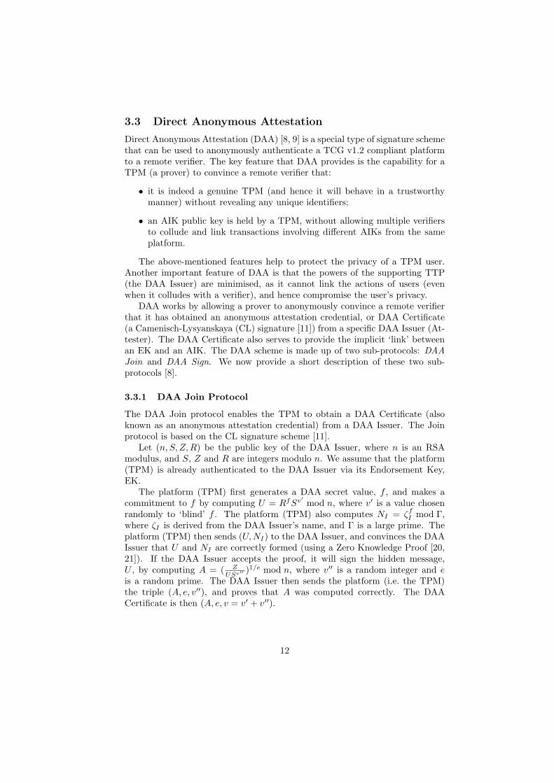
The CDP watermarking scheme involves three distinct phases (as shown inFigure 5), namely, the Join Phase, the Watermarking Phase, and the ContentAcquisition Phase. We now describe each phase in greater detail.
Figure 5: An Anonymous Watermarking Scheme using Trusted Computing
26

Join Phase The objective of the Join Phase is for a buyer platform to obtaina DAA Certificate from a DAA Issuer. Since the Join Phase of the schemeis identical to the DAA Join Protocol of section 3.2, we do not describe thesequence of Join Phase steps. Note that the Join Phase may have taken placebefore a device is shipped to the content buyer.
Watermarking Phase The aim of this phase is for a buyer to contribute awatermark, and for the seller to embed the buyer’s watermark into a piece ofproprietary content. The entities involved in this phase are the Buyer Platform,BP and the Seller, S. The sequence of events is as follows:
1. BP generates a watermark, W , using the watermark generation function ofa reliable watermarking algorithm (e.g. the spread spectrum watermarkingalgorithm given in [14]).
2. BP generates an encryption key pair (BEKpk ,BEKsk ), and encrypts thewatermark, W , using BEKpk, to create:
EncBEKPK (W ).
3. BP (i.e. the TPM) generates a non-migratable signing key pair (BSKpk ,BSKsk ).BP then signs the encrypted watermark, EncBEKpk
(W ) (from step 2), andBEK pk, to obtain:
SigBSKsk(EncBEKpk
(W ),BEKpk ).
4. BP generates an AIK key pair, (AIK pk ,AIK sk ).
5. BP retrieves the Stored Measurement Log (SML), and the correspondingPlatform Configuration Register (PCR) values. BP then signs the PCRvalues using AIK sk (from step 4):
SigAIKsk(PCR).
The SML and PCR values provide evidence that a particular watermarkingalgorithm was used (by the buyer) to generate the watermark.
6. BP computes ζ = H(IDS ). It then creates a pseudonym, Nv = ζf (wheref is the DAA Secret generated during the join phase) for use when inter-acting with the seller.
7. To prove (to the seller) that the AIK (from step 4) originates from a gen-uine TPM, the platform DAA-Signs AIKpk using f , the DAA Certificate,and the other public parameters of the system. The output of DAA Signis the DAA Signature, σ (which also includes ζ and Nv).
8. To prove that BSK originates from the TPM, BP signs (certifies) BSKpk
using AIKsk :
SigAIKsk(BSKpk ).
27

9. BP sends the following to the Seller:
BP → S :EncBEKpk(W ),AIKpk ,BSKpk ,BEKpk ,
σ,SigBSKsk(EncBEKpk
(W ),BEKpk ),SigAIKsk
(BSKpk ),SML,SigAIKsk(PCR).
On receiving the last message from the buyer, and, to subsequently incor-porate the buyer’s watermark into a piece of content, the seller S performs thefollowing steps:
1. Verifies the DAA Signature, σ, and is thus convinced that:
• BP is in possession of a legitimate DAA Certificate from a specificDAA Issuer, which implies that a genuine TPM is contained in BP.
• AIKpk was signed using BP ’s DAA Secret, f . Even though the valueof f is never revealed to the seller, the seller knows that the value isrelated to the one in the DAA Certificate.
2. Examines the integrity measurements of the buyer platform. This isachieved by recursively hashing the values in the SML, and then com-paring the result with the corresponding PCR values. If the outcome issatisfactory, the seller is convinced that a reliable watermarking algorithmwas used by the buyer platform to generate its watermark, W .
3. Verifies SigAIKsk(BSKpk ).
4. Verifies SigBSKsk(EncBEKpk
(W ),BEKpk ).
5. Generates a seller watermark, V , and then embeds it into the Content,X, to create:
X ′ = X ⊗ V.
6. Encrypts X ′ (from step 3) using BEKpk to obtain:
E(X ′) = EncBEKpk(X ′).
7. Permutes EncBEKpk(W ) (received from buyer) to obtain E(ρW ).
8. The permuted watermark is then embedded into X ′ as follows:
E(X ′ ⊗ ρW ) = E(X ′)⊗ E(ρW ),
which follows because of the homomorphic property of the encryptionalgorithm.
9. The encrypted, watermarked content is then sent back to the buyer.
S → BP : E(X ′ ⊗ ρW ).
28

Content Acquisition Phase When the buyer receives the encrypted, wa-termarked content, E(X ′ ⊗ ρW ), from the seller, the buyer decrypts it usingBEK sk, to retrieve the watermarked content:
(X ′ ⊗ ρW ).
The watermarked content is now ready for consumption (e.g. viewing orlistening) by the buyer.
6.3 Analysis and Discussion
The watermarking scheme presented here meets all the security requirementsidentified earlier in section 6.1. The interested reader is referred to [32] for amore detailed security analysis. This watermarking scheme is suitable for usein a mobile ubiquitous environment for the following reasons.
Firstly, as mentioned in section 2.2, having access to an online TTP maynot be feasible in such an environment. To protect privacy, and using DAA, abuyer only has to interact with the DAA Issuer (the online TTP here) once,and he/she can subsequently generate verifiable pseudonyms on his/her ownand interact with buyers.
Secondly, the scheme is extremely efficient in terms of communications over-head, because only two messages need to be exchanged between the contentbuyer and a seller. In a mobile environment, where users are predominantlyusing resource constrained devices, communications efficiency is an importantfeature.
6.4 The Future
We have presented just one example of a scheme exploiting the features offeredby trusted computing for the purpose of protecting content distributed to mo-bile devices. If trusted computing functionality becomes as widespread as iscommonly expected, then a variety of other such schemes are likely to be pro-posed. This appears to be an area of considerable promise for future researchand exploitation.
7 Concluding Remarks
We have considered three ways in which trusted computing can help to addresssome of the most pressing security and privacy issues arising in future mobileubiquitous networks. However, there are doubtless many other ways in whichtrusted computing can be exploited to help provide security for future mobilenetworks. If trusted computing technology becomes as ubiquitous as is envisagedby the technology’s developers, then this is clearly an area of huge importancefor the future. TPMs are already present in very large numbers of PCs on saletoday, and it seems only a matter of time before similar functionality spreadsto a wide range of mobile computing devices.
29

Other work on exploiting trusted computing functionality to provide securityin mobile ubiquitous computing environments is already emerging. The workof Balfe, Lakhani and Paterson [4, 5] on using trusted computing to providestable addresses in a peer-to-peer environment, and hence avoid Sybil attacks,has already been mentioned in section 1. The use of trusted computing’s attes-tation mechanisms to detect node compromise in wireless sensor networks [29]has been proposed by Krauß, Stumpf and Eckrt. Other relevant work includesthe efforts of the Mobile Phone Working Group of the TCG, as outlined in[17], the work of Kinateder and Pearson on using trusted computing to sup-port a distributed reputation system [28], the use of trusted computing forsecuring the access, distribution and storage of confidential documents in a net-worked enterprise environments for mobile workers [51], as proposed by Sevinc,Strasser and Basin, and the possible use of trusted computing functionality toprovide greater security for end nodes in peer-to-peer networks, as discussed bySchechter, Greenstadt and Smith [49].
Like any other technological innovation, trusted computing is no silver bul-let. The technology is still evolving, and open issues remain. One such issue,highlighted by McCune et al. [33], is the turtle problem, i.e. the problem of es-tablishing the first point of trust for the purpose of user based attestation in anetwork environment. Another area of considerable recent interest involves pos-sible means of generalising the attestation mechanism, which is seen by many astoo coarse and difficult to manage. Such work includes Shi et al.’s fine-grainedcode attestation [52], and property-based attestation [26, 47].
One technology likely to be fundamental to the deployment of trusted com-puting in general purpose computing platforms is virtualisation. This technologyprovides the ability to run multiple ‘virtual machines’ (VMs) on one physicalplatform, managed by a ‘hypervisor’ or Virtual Machine Monitor (VMM). Eachvirtual machine hosts a self-contained operating system or task-specific software.The VMs are isolated from each other, and one VM cannot access memory spaceallocated to another VM — the VMM ensures this with assistance from hard-ware enhancements. For example, Intel’s LaGrande technology [24] provideshardware support enabling the creation of secure (and measurable) compart-ments for virtual machines. Virtualisation can be used to enhance the securityproperties of a trusted platform — for example, Haldar et al. [26] have proposedmethods for extending platform integrity measuring to virtual machines.
Indeed, trusted computing could become a ubiquitous security infrastruc-ture, used routinely in the provision of almost every security service — indeed,this would appear to be part of the vision of the TCG (see, for example, [45]). Ittherefore would seem prudent to further explore ways in which such technologycan be exploited to solve some of the most difficult problems facing users anddesigners of ubiquitous computing systems, not least such issues as user privacyand trust establishment.
30

Acknowledgements
The work reported in this chapter has formed part of the Ubiquitous ServicesCore Research Programme of the Virtual Centre of Excellence in Mobile &Personal Communications, Mobile VCE, www.mobilevce.com. This researchhas been funded by the DTI-led Technology Programme and by the IndustrialCompanies who are Members of Mobile VCE. Fully detailed technical reportson this research are available to Industrial Members of Mobile VCE.
References
[1] R. Anderson. Cryptography and competition policy: Issues with ‘trustedcomputing’. In Proceedings of the 22nd annual symposium on Principlesof Distributed Computing (PODC ’03), Boston, Massachusetts, US, July13–16, 2003, pages 3–10. ACM Press, 2003.
[2] R. C. Atkinson, J. Irvine, J. Dunlop, and S. Vadagama. The personaldistributed environment. IEEE Wireless Communications, 14(2):62–69,April 2007.
[3] B. Balacheff, L. Chen, S. Pearson, D. Plaquin, and G. Proudler. TrustedComputing Platforms: TCPA Technology in Context. Prentice Hall PTR,Upper Saddle River, New Jersey, 2003.
[4] S. Balfe, A. D. Lakhani, and K. G. Paterson. Securing peer-to-peer net-works using trusted computing. In C. J. Mitchell, editor, Trusted Comput-ing, chapter 10, pages 271–298. IEE Press, London, 2005.
[5] S. Balfe, A. D. Lakhani, and K. G. Paterson. Trusted computing: Providingsecurity for peer-to-peer networks. In Proceedings of the Fifth InternationalConference on Peer-to-Peer Computing (P2P ’05), Konstanz, Germany,August 31–September 2, 2005, pages 117–124. IEEE Computer Society,Aug-Sep 2005.
[6] F. Bao and R. H. Deng. Privacy protection for transactions of digitalgoods. In S. Qing, T. Okamoto, and J. Zhou, editors, Third InternationalConference on Information and Communications Security (ICICS 2001),Xian, China, November 13–16, 2001. Proceedings, volume 2229 of LectureNotes in Computer Science, pages 202–213. Springer-Verlag, Berlin, 2001.
[7] B. Berendt, O. Gunther, and S. Spiekermann. Privacy in e-commerce:Stated preferences vs. actual behavior. Communications of the ACM,48(4):101–106, 2005.
[8] E. Brickell, J. Camenisch, and L. Chen. Direct anonymous attestation. InProceedings of the 11th ACM Conference on Computer and Communica-tions Security, Washington DC, USA, October 25–29, 2004, pages 132–145.ACM Press, 2004.
31

[9] E. Brickell, J. Camenisch, and L. Chen. The DAA scheme in context. InC. J. Mitchell, editor, Trusted Computing, chapter 5, pages 143–174. IEEPress, London, 2005.
[10] J. Camenisch. Efficient anonymous fingerprinting with group signatures.In T. Okamoto, editor, Advances in Cryptology — ASIACRYPT 2000,6th International Conference on the Theory and Application of Cryptologyand Information Security, Kyoto, Japan, December 3–7, 2000, Proceed-ings, volume 1976 of Lecture Notes in Computer Science, pages 415–428.Springer-Verlag, 2000.
[11] J. Camenisch and A. Lysyanskaya. A signature scheme with efficient proto-cols. In S. Cimato, C. Galdi, and G. Persiano, editors, Third Conference onSecurity in Communication Networks (SCN 2002), Amalfi, Italy, Septem-ber 12–13, 2002. Proceedings, volume 2576 of Lecture Notes in ComputerScience, pages 268–289. Springer-Verlag, Berlin, 2003.
[12] D. Chakraborty, A. Joshi, Y. Yesha, and T. Finin. Toward distributedservice discovery in pervasive computing environments. IEEE Transactionson Mobile Computing, 5(2):97–112, 2006.
[13] J.-G. Choi, K. Sakurai, and J.-H. Park. Does it need trusted third party?Design of buyer-seller watermarking protocolwithout trusted third party.In J. Zhou, M. Yung, and Y. Han, editors, First International Conferenceon Applied Cryptography and Network Security (ACNS 2003), Kunming,China, October 16–19, 2003. Proceedings, volume 2846 of Lecture Notes inComputer Science, pages 265–279. Springer-Verlag, Berlin, 2003.
[14] I. J. Cox, J. Killian, T. Leighton, and T. Shamoon. Secure spread spectrumwatermarking for multimedia. IEEE Transactions on Image Processing,6(12):1673–1687, 1997.
[15] J. Dunlop, R. C. Atkinson, J. Irvine, and D. Pearce. A personal distributedenvironment for future mobile systems. In Proceedings of 12th IST Mo-bile and Wireless Communications Summit, Aveiro, Portugal, June 15–18,2003, pages 705–709. Instituto de Telecomunicacoes, Jun 2003.
[16] A. Friday, N. Davies, N. Wallbank, E. Catterall, and S. Pink. Supportingservice discovery, querying and interaction in ubiquitous computing envi-ronments. Wireless Networks, 10(6):631–641, 2004.
[17] E. M. Gallery and C. J. Mitchell. Trusted mobile platforms. In A. Al-dini and R. Gorrieri, editors, Foundations of Security Analysis and DesignIV: FOSAD 2006/2007 Tutorial Lectures, volume 4677 of Lecture Notes inComputer Science, pages 282–323. Springer-Verlag, Berlin, 2007.
[18] E. M. Gallery and A. Tomlinson. Secure delivery of conditional access ap-plications to mobile receivers. In C. J. Mitchell, editor, Trusted Computing,chapter 7, pages 195–237. IEE Press, London, 2005.
32

[19] C. Gehrmann, C. J. Mitchell, and K. Nyberg. Manual authentication forwireless devices. Cryptobytes, 7(1):29–37, 2004.
[20] O. Goldreich, S. Micali, and A. Wigderson. Proofs that yield nothing buttheir validity or all languages in NP have zero-knowledge proof systems.Journal of the ACM, 38(3):690–728, 1991.
[21] S. Goldwasser, S. Micali, and C. Rackoff. The knowledge complexity ofinteractive proof systems. SIAM Journal on Computing, 18(1):186–208,1989.
[22] S. K. Goo, J. Irvine, and R. Atkinson. Personal distributed environmentsecuring the dynamic service platformsbeyond 3G. In Proceedings of 4thInternational Conference on 3G Mobile Communication Technologies, Lon-don, UK, June 25–27, 2003, pages 18–22. IEE Conference Publication 494,2003.
[23] S. K. Goo, J. Irvine, J. Dunlop, A. Tomlinson, and S. Schwiderski-Grosche.Security requirements for mobile service provision via a digital marketplace.In Proceedings of 11th European Wireless Conference (EW 2005), Nicosia,Cyprus, April 10–13, 2005, volume 2, pages 573–581, 2005.
[24] D. Grawrock. The Intel safer computing initiative: building blocks fortrusted computing. Intel Press, 2006.
[25] E. Guttman, C. Perkins, J. Veizades, and M. Day. Service Location Pro-tocol, Version 2. RFC 2608, The Internet Engineering Task Force (IETF),June 1999.
[26] V. Haldar, D. Chandra, and M. Franz. Semantic remote attestation — Avirtual machine directed approach to Trusted Computing. In Proceedingsof the 3rd USENIX Virtual Machine Research & Technology Symposium(VM ’04), San Jose, CA, USA, May 6–7, 2004, pages 29–41. USENIX,May 2004.
[27] H. S. Ju, H. J. Kim, D. H. Lee, and J. I. Lim. An anonymous buyer-sellerwatermarking protocol with anonymity control. In P. J. Lee and C. H.Lim, editors, 5th International Conference on Information Security andCryptology (ICISC 2002), Seoul, Korea, November 28–29, 2002. Proceed-ings, volume 2587 of Lecture Notes in Computer Science, pages 421–432.Springer-Verlag, Berlin, 2002.
[28] M. Kinateder and S. Pearson. A privacy-enhanced peer-to-peer reputationsystem. In K. Bauknecht, A. Min Tjoa, and G. Quirchmayr, editors, E-Commerce and Web Technologies, 4th International Conference, EC-Web,Prague, Czech Republic, September 2–5, 2003, Proceedings, volume 2738 ofLecture Notes in Computer Science, pages 206–216. Springer-Verlag, Berlin,2003.
33

[29] C. Krauß, F. Stumpf, and C. Eckert. Detecting node compromise in hy-brid wireless sensor networks using attestation techniques. In F. Stajano,C. Meadows, S. Capkun, and T. Moore, editors, 4th European Workshop onSecurity and Privacy in Ad-hoc and Sensor Networks (ESAS 2007), Cam-bridge, UK, July 2–3, 2007. Proceedings, volume 4572 of Lecture Notes inComputer Science, pages 203–217. Springer-Verlag, Berlin, 2007.
[30] C.-L. Lei, P.-L. Yu, P.-L. Tsai, and M.-H. Chan. An efficient and anony-mous buyer-seller watermarking protocol. IEEE Transactions on ImageProcessing, 13(12):1618–1626, 2004.
[31] A. Leung and C. J. Mitchell. Ninja: Non identity based, privacy preservingauthentication for ubiquitousenvironments. In J. Krumm, G. D. Abowd,A. Seneviratne, and T. Strang, editors, 9th International Conference onUbiquitous Computing (Ubicomp 2007), Innsbruck, Austria, September 16–19, 2007. Proceedings, volume 4717 of Lecture Notes in Computer Science,pages 73–90. Springer-Verlag, Berlin, 2007.
[32] A. Leung and G. S. Poh. An anonymous watermarking scheme for contentdistribution protection using trusted computing. In Proceedings of the In-ternational Conference on Security and Cryptography (SECRYPT 2007),Barcelona, Spain, August 28–31, 2007, pages 319–326. INSTICC Press,2007.
[33] J. M. McCune, A. Perrig, A. Seshadri, and L. van Doorn. Turtles all theway down: Research challenges in user-based attestation. In Proceedingsof the 2nd USENIX Workshop on Hot Topics in Security (HotSec ’07),Boston, MA, USA, August 7, 2007, 2007.
[34] N. Memon and P. W. Wong. A buyer-seller watermarking protocol. IEEETransactions on Image Processing, 10(4):643–649, 2001.
[35] C. J. Mitchell, editor. Trusted Computing. IEE Press, London, 2005.
[36] W. Mohr. The wireless world research forum — WWRF. Computer Com-munications, 26(1):2–10, Jan 2003.
[37] National Institute of Standards and Technology (NIST). Secure Hash Stan-dard. Federal information processing standards publication (FIPS) 180-2,2002.
[38] M. Nidd. Service discovery in DEAPspace. IEEE Personal Communica-tions, 8(4):39–45, 2001.
[39] N. Niebert, A. Schieder, H. Abramowicz, G. Malmgren, J. S. C. Prehofer,and H. Karl. Ambient networks: An architecture for communication be-yond 3G. IEEE Wireless Communications, 11(2):14–22, April 2004.
34

[40] I. G. Niemegeers and S. M. H. de Groot. Research issues in ad-hoc dis-tributed personal networking. Wireless Personal Communications, 26(2–3):149–167, 2003.
[41] J. O’Sullivan, D. Edmond, and A. Hofstede. What’s in a service? Towardsaccurate description of non-functional service properties. Distributed andParallel Databases Journal, 12(2/3):117–133, 2002.
[42] P. Paillier. Public-key cryptosystems based on composite degree residuosityclasses. In J. Stern, editor, EUROCRYPT ’99, Prague, Czech Republic,May 2–6, 1999. Proceedings, volume 1592 of Lecture Notes in ComputerScience, pages 223–238. Springer-Verlag, Berlin, 1999.
[43] B. Pfitzmann and M. Schunter. Asymmetric fingerprinting. In U. M. Mau-rer, editor, EUROCRYPT ’96, Zaragoza, Spain, May 12-16, 1996. Pro-ceedings, volume 1070 of Lecture Notes in Computer Science, pages 84–95.Springer-Verlag, Berlin, 1996.
[44] B. Pfitzmann and M. Waidner. Anonymous fingerprinting. In W. Fumy,editor, EUROCRYPT ’97, Konstanz, Germany, May 11–15, 1997. Pro-ceedings, volume 1233 of Lecture Notes in Computer Science, pages 88–102.Springer-Verlag, Berlin, 1997.
[45] G. J. Proudler. Concepts of trusted computing. In C. J. Mitchell, editor,Trusted Computing, chapter 2, pages 11–27. IEE Press, London, 2005.
[46] J. Rosenburg, H. Schulzrinne, G. Camarillo, A. Johnston, J. Peterson,R. Sparks, M. Handley, and E. Schooler. SIP: Session initiation protocol.RFC 3261, Internet Engineering Task Force, Jun 2002.
[47] A.-R. Sadeghi and C. Stuble. Property-based attestation for computingplatforms: Caring about properties, not mechanisms. In Proceedings ofthe 2004 Workshop on New Security Paradigms (NSPW ’04), Nova Scotia,Canada, September 20–23, 2004, pages 67–77. ACM Press, 2004.
[48] Salutation Consortium. Salutation Architecture Specification, June 1999.http://www.salutation.org/.
[49] S. E. Schechter, R. A. Greenstadt, and M. D. Smith. Trusted computing,peer-to-peer distribution, and the economics of pirated entertainment. InProceedings of The Second Annual Workshop on Economics and Informa-tion Security, 2003. College Park, Maryland, May 29–30, 2003.
[50] S. Schwiderski-Grosche, A. Tomlinson, and D. B. Pearce. Towards the se-cure initialisation of a personal distributed environment. Technical ReportRHUL–MA–2005–9, Mathematics Department, Royal Holloway, Universityof London, July 2005.
35

[51] P. E. Sevinc, M. Strasser, and D. A. Basin. Securing the distributionand storage of secrets with trusted platform modules. In D. Sauveron,K. Markantonakis, A. Bilas, and J.-J. Quisquater, editors, First Inter-national Workshop in Information Security Theory and Practices: SmartCards, Mobile and Ubiquitous Computing Systems (WISTP 2007), Herak-lion, Crete, Greece, May 9–11, 2007. Proceedings, volume 4462 of LectureNotes in Computer Science, pages 53–66. Springer-Verlag, Berlin, 2007.
[52] E. Shi, A. Perrig, and L. V. Doorn. BIND: A fine-grained attestationservice for secure distributed systems. In Proceedings of the 2005 IEEESymposium on Security and Privacy, Oakland, CA, USA, May 8–11, 2005,pages 154–168. IEEE Press, 2005.
[53] Sun Microsystems. Jini Architecture Specification. Version1.2, Sun Microsystems, Palo Alto, CA, USA, December 2001.http://www.sun.com/software/jini/specs/.
[54] Trusted Computing Group (TCG). TPM v1.2 Specification Changes. Asummary of changes, Trusted Computing Group, Portland, Oregon, USA,October 2003.
[55] Trusted Computing Group (TCG). TCG Specification ArchitectureOverview. Version 1.2, The Trusted Computing Group, Portland, Oregon,USA, April 2004.
[56] Universal Plug and Play (UPnP) Forum. UPnP Device Architecture. ver-sion 1.0, December 2003. http://www.upnp.org/.
[57] M. Waldvogel, G. Caronni, D. Sun, N. Weiler, and B. Plattner. The ver-sakey framework: versatile group key management. IEEE Journal on Se-lected Areas in Communications, 17(9):1–16, Aug 1999.
[58] D. Wallner, E. Harder, and R. Agee. Key management for multicast: Issuesand architectures. RFC 2627, Internet Engineering Task Force, Jun 1999.
[59] C. K. Wong, M. Gouda, and S. S. Lam. Secure group communicationsusing key graphs. IEEE/ACM Transactions on Networking, 8(1):16–30,Feb 2000.
[60] F. Zhu, M. Mutka, and L. Li. Service discovery in pervasive computingenvironments. IEEE Pervasive Computing, 4(4):81–90, 2005.
36