Embed Size (px)
Citation preview
32nd Gas-Lift WorkshopThe Hague, The Netherlands
February 2 - 6, 2009
This presentation is the property of the author(s) and his/her/their company(ies).It may not be used for any purpose other than viewing by Workshop attendees without the expressed written permission of the author(s).
Using Valve Performance in
Gas Lift Design SoftwareTom Nations
Feb. 2 - 6, 2009 2009 Gas-Lift Workshop 2
Contents
• Definition of Valve Performance.• Differences between some of the available flow
correlations.• Valve Performance availability in gas lift design
software programs.• Using Valve Performance in Gas Lift Design.• What can happen if Valve Performance is not
considered.
Feb. 2 - 6, 2009 2009 Gas-Lift Workshop 3
Valve Performance
• Valve Performance is the determination of the actual flow rate through a gas lift valve at different combinations of Pvo, temperature and Piod.– Each make and model of gas lift valve is
somewhat different .– Bellows load rate and effective stem travel
must be determined.– Performance curves generated from dynamic
tests.
Feb. 2 - 6, 2009 2009 Gas-Lift Workshop 4
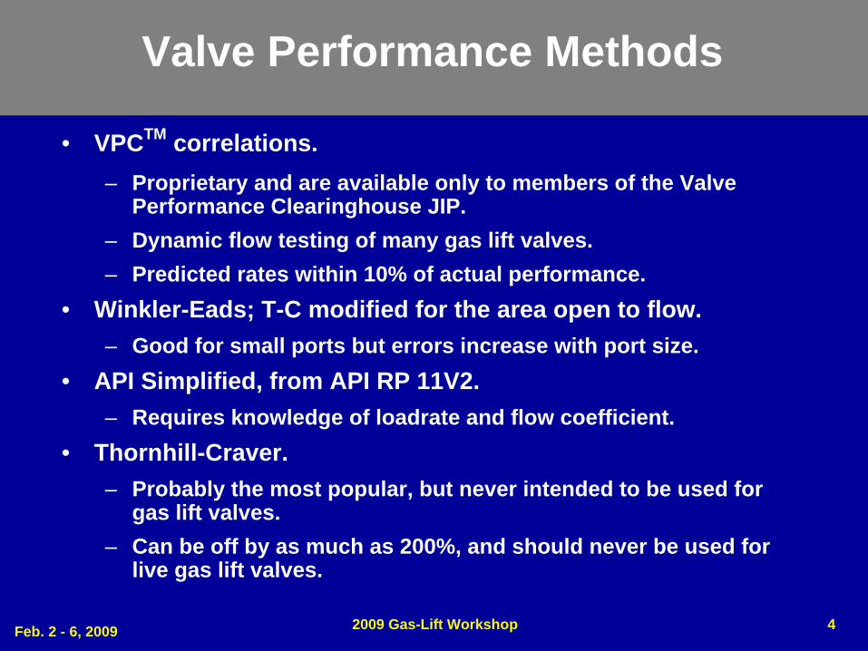
Valve Performance Methods
• VPCTM correlations.– Proprietary and are available only to members of the Valve
Performance Clearinghouse JIP.– Dynamic flow testing of many gas lift valves.– Predicted rates within 10% of actual performance.
• Winkler-Eads; T-C modified for the area open to flow.– Good for small ports but errors increase with port size.
• API Simplified, from API RP 11V2.– Requires knowledge of loadrate and flow coefficient.
• Thornhill-Craver.– Probably the most popular, but never intended to be used for
gas lift valves.– Can be off by as much as 200%, and should never be used for
live gas lift valves.
Feb. 2 - 6, 2009 2009 Gas-Lift Workshop 5
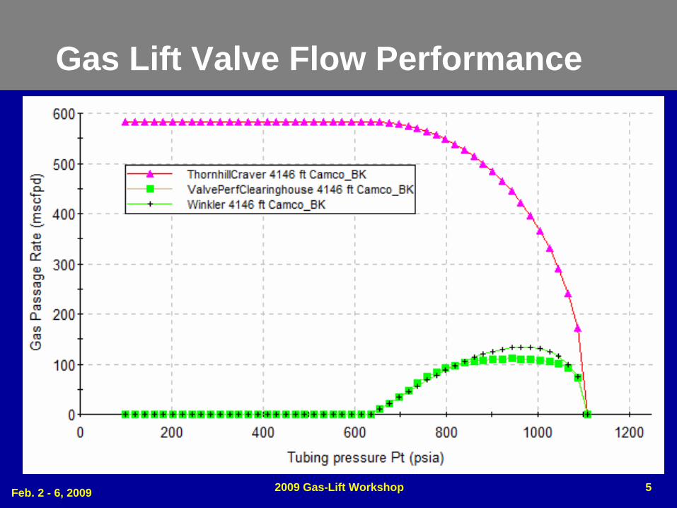
Gas Lift Valve Flow Performance
Feb. 2 - 6, 2009 2009 Gas-Lift Workshop 6
Valve Performance in software programs
• SNAP– Ryder Scott, LLC.
• WellFlow– Weatherford
• WinGLUE– AppSmiths
• PROSPER– Petroleum Experts
Feb. 2 - 6, 2009 2009 Gas-Lift Workshop 7
Using Valve Performance
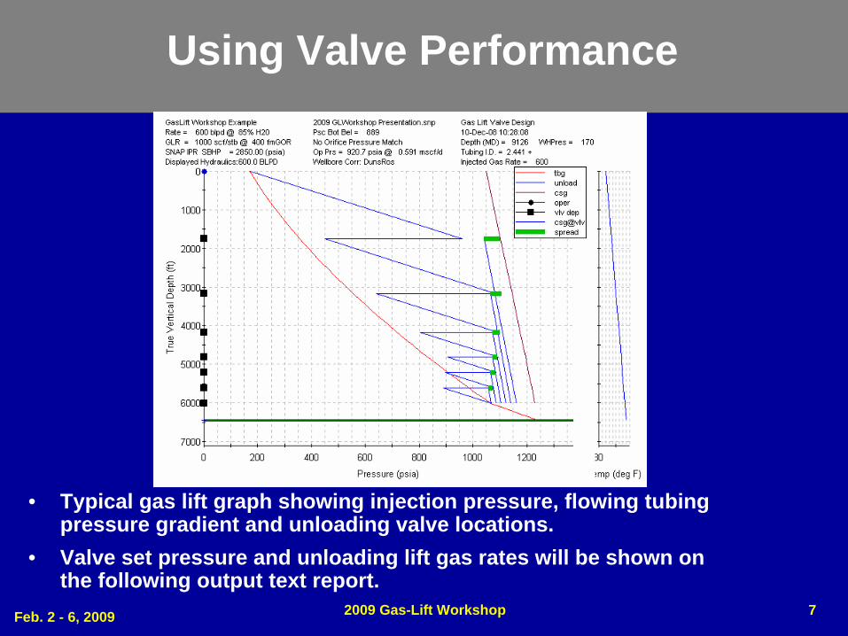
• Typical gas lift graph showing injection pressure, flowing tubing pressure gradient and unloading valve locations.
• Valve set pressure and unloading lift gas rates will be shown on the following output text report.
Feb. 2 - 6, 2009 2009 Gas-Lift Workshop 8
Gas Lift Design Output Report
Feb. 2 - 6, 2009 2009 Gas-Lift Workshop 9
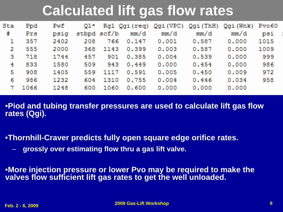
•Piod and tubing transfer pressures are used to calculate lift gas flow rates (Qgi).
•Thornhill-Craver predicts fully open square edge orifice rates.– grossly over estimating flow thru a gas lift valve.
•More injection pressure or lower Pvo may be required to make the valves flow sufficient lift gas rates to get the well unloaded.
Calculated lift gas flow rates
Feb. 2 - 6, 2009 2009 Gas-Lift Workshop 10
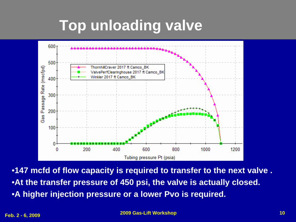
Top unloading valve
•147 mcfd of flow capacity is required to transfer to the next valve .•At the transfer pressure of 450 psi, the valve is actually closed.•A higher injection pressure or a lower Pvo is required.
Feb. 2 - 6, 2009 2009 Gas-Lift Workshop 11
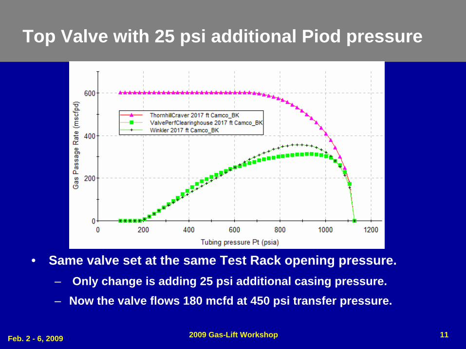
Top Valve with 25 psi additional Piod pressure
• Same valve set at the same Test Rack opening pressure.– Only change is adding 25 psi additional casing pressure.– Now the valve flows 180 mcfd at 450 psi transfer pressure.
Feb. 2 - 6, 2009 2009 Gas-Lift Workshop 12
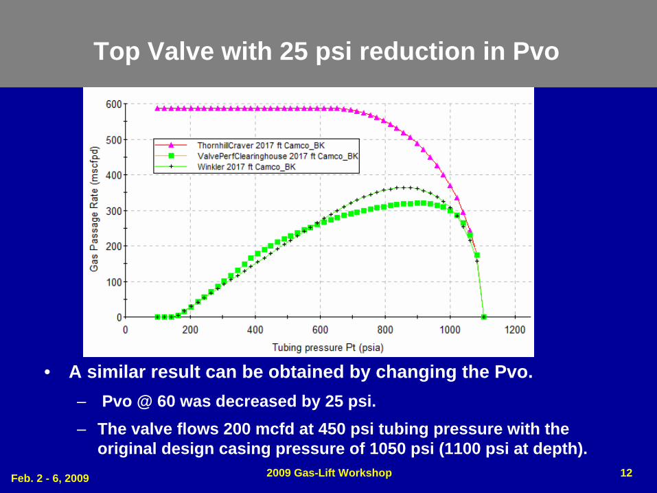
Top Valve with 25 psi reduction in Pvo
• A similar result can be obtained by changing the Pvo.– Pvo @ 60 was decreased by 25 psi.– The valve flows 200 mcfd at 450 psi tubing pressure with the
original design casing pressure of 1050 psi (1100 psi at depth).
Feb. 2 - 6, 2009 2009 Gas-Lift Workshop 13
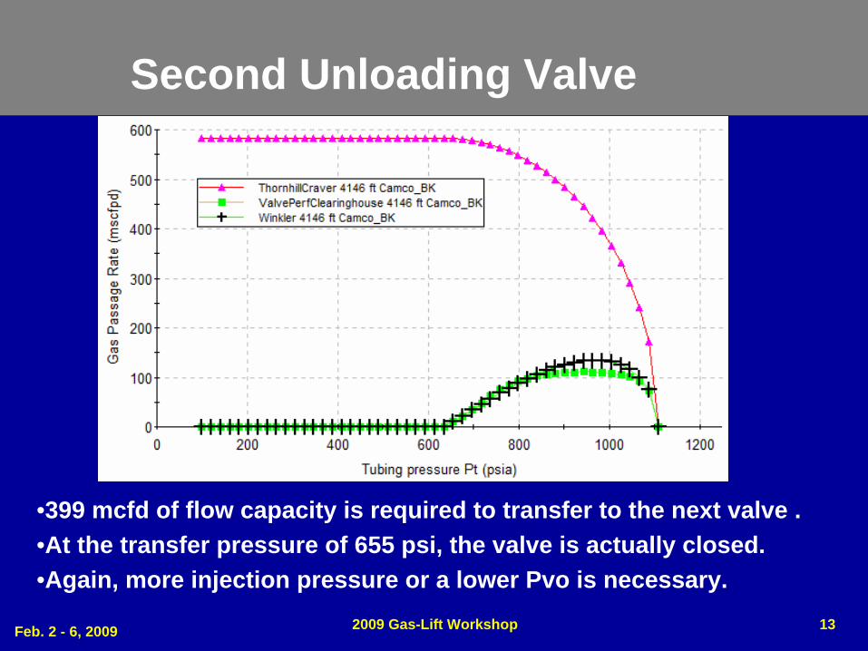
Second Unloading Valve
•399 mcfd of flow capacity is required to transfer to the next valve .•At the transfer pressure of 655 psi, the valve is actually closed.•Again, more injection pressure or a lower Pvo is necessary.
Feb. 2 - 6, 2009 2009 Gas-Lift Workshop 14
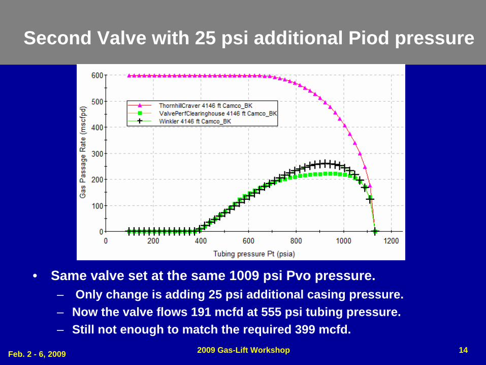
Second Valve with 25 psi additional Piod pressure
• Same valve set at the same 1009 psi Pvo pressure.– Only change is adding 25 psi additional casing pressure.– Now the valve flows 191 mcfd at 555 psi tubing pressure.– Still not enough to match the required 399 mcfd.
Feb. 2 - 6, 2009 2009 Gas-Lift Workshop 15
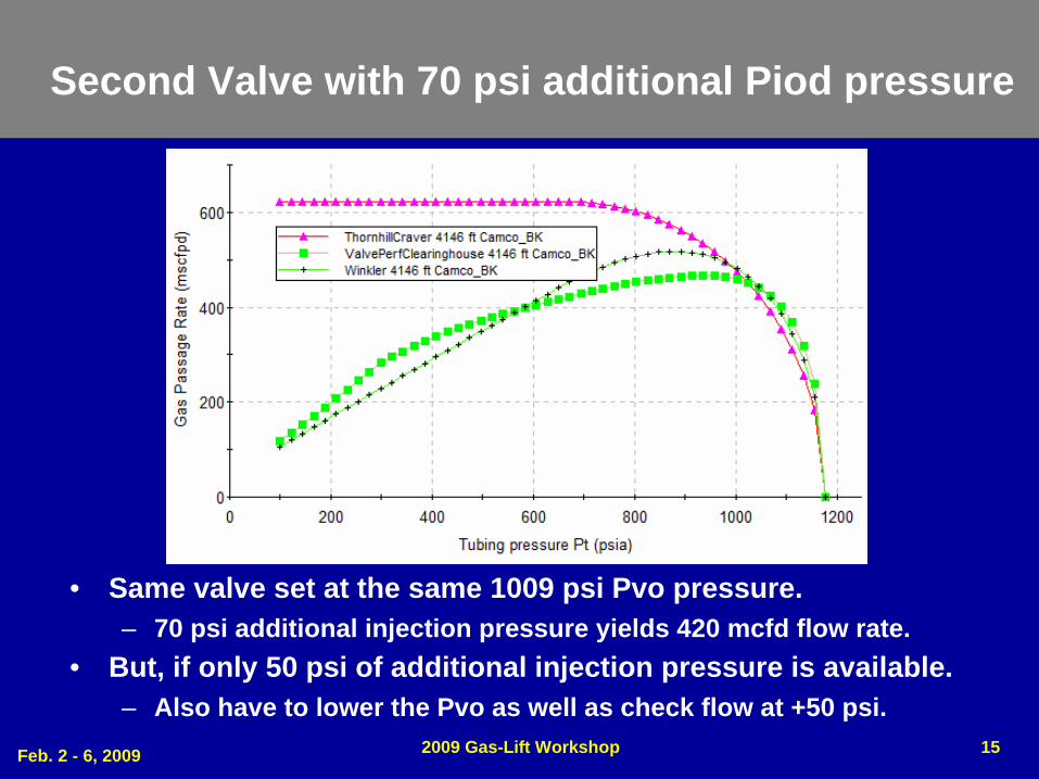
Second Valve with 70 psi additional Piod pressure
• Same valve set at the same 1009 psi Pvo pressure.– 70 psi additional injection pressure yields 420 mcfd flow rate.
• But, if only 50 psi of additional injection pressure is available.– Also have to lower the Pvo as well as check flow at +50 psi.
Feb. 2 - 6, 2009 2009 Gas-Lift Workshop 16
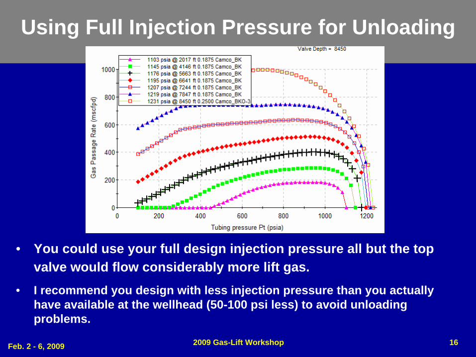
Using Full Injection Pressure for Unloading
• You could use your full design injection pressure all but the top valve would flow considerably more lift gas.
• I recommend you design with less injection pressure than you actually have available at the wellhead (50-100 psi less) to avoid unloading problems.
Feb. 2 - 6, 2009 2009 Gas-Lift Workshop 17
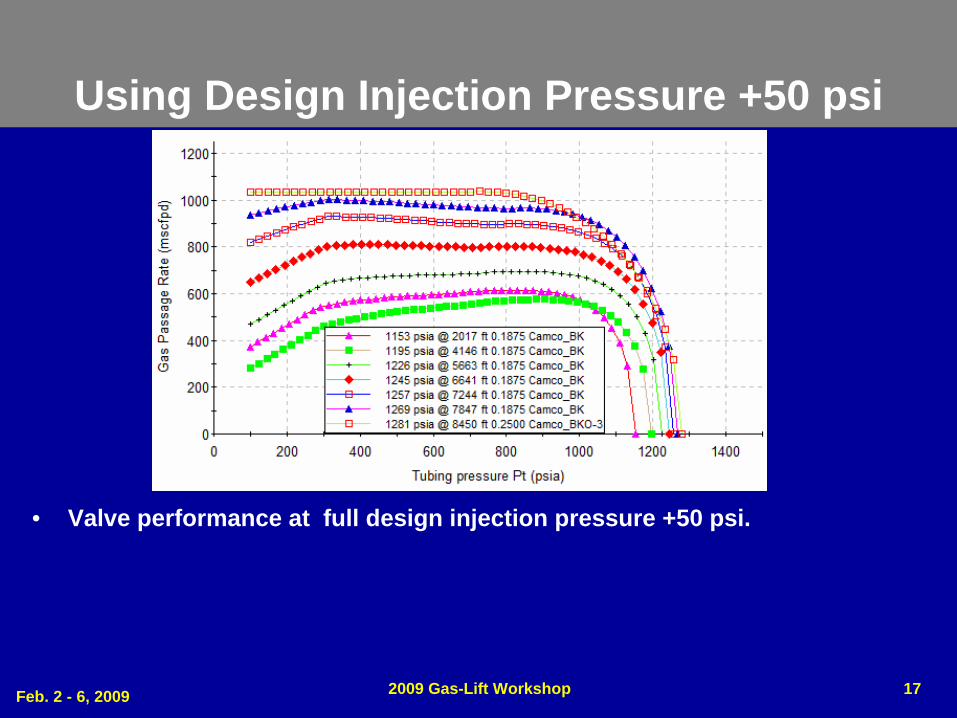
Using Design Injection Pressure +50 psi
• Valve performance at full design injection pressure +50 psi.
Feb. 2 - 6, 2009 2009 Gas-Lift Workshop 18
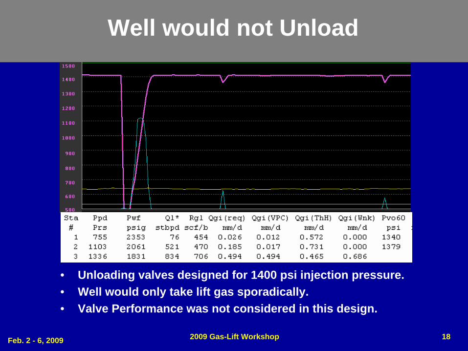
Well would not Unload
• Unloading valves designed for 1400 psi injection pressure.• Well would only take lift gas sporadically.• Valve Performance was not considered in this design.
Feb. 2 - 6, 2009 2009 Gas-Lift Workshop 19
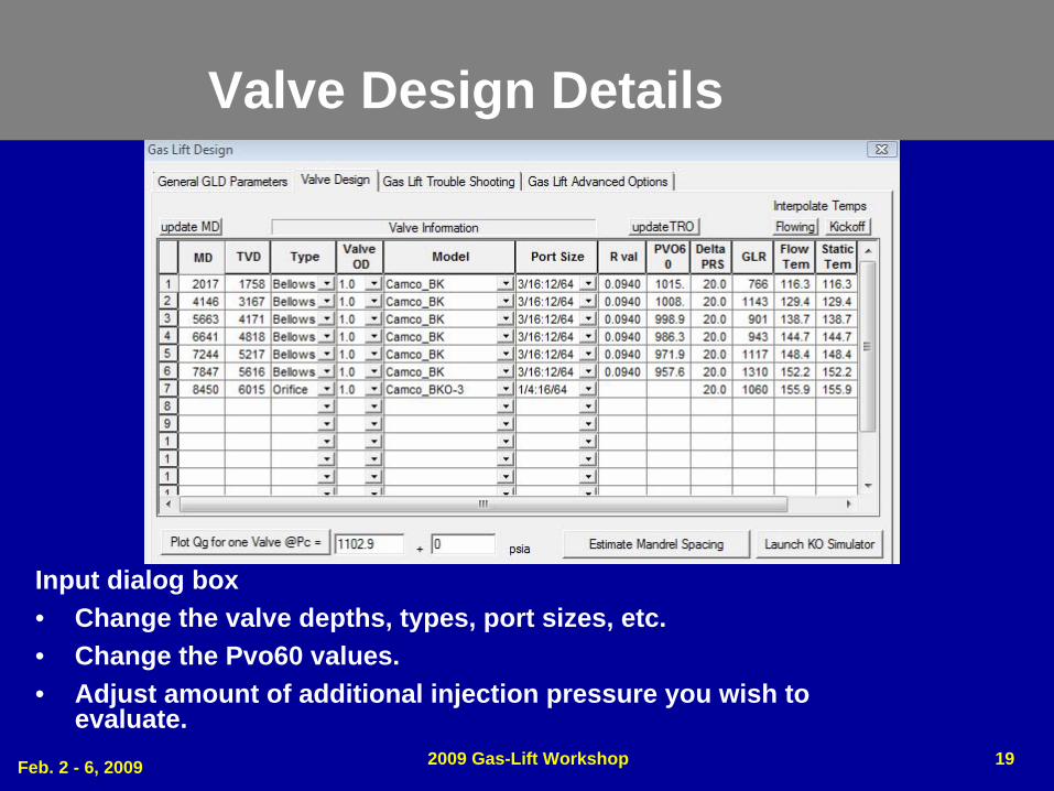
Valve Design Details
Input dialog box• Change the valve depths, types, port sizes, etc.• Change the Pvo60 values.• Adjust amount of additional injection pressure you wish to
evaluate.
Feb. 2 - 6, 2009 2009 Gas-Lift Workshop 20
Re-cap
• Definition of Valve Performance.• Differences between some of the available flow
correlations.• Valve Performance availability in gas lift design
software programs.• Using Valve Performance in Gas Lift Design.
Feb. 2 - 6, 2009 2009 Gas-Lift Workshop 21
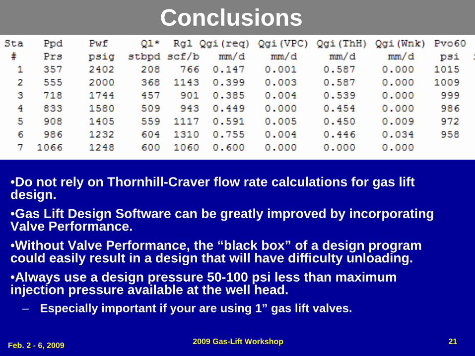
•Do not rely on Thornhill-Craver flow rate calculations for gas lift design.•Gas Lift Design Software can be greatly improved by incorporating Valve Performance.•Without Valve Performance, the “black box” of a design program could easily result in a design that will have difficulty unloading.•Always use a design pressure 50-100 psi less than maximum injection pressure available at the well head.
– Especially important if your are using 1” gas lift valves.
Conclusions
Feb. 2 - 6, 2009 2009 Gas-Lift Workshop 22
CopyrightRights to this presentation are owned by the company(ies) and/or author(s) listed on the title page. By submitting this presentation to the Gas-Lift Workshop, they grant to the Workshop, the Artificial Lift Research and Development Council (ALRDC), and the American Society of Mechanical Engineers (ASME), rights to:
– Display the presentation at the Workshop.– Place it on the www.alrdc.com web site, with access to the site to be as
directed by the Workshop Steering Committee.– Place it on a CD for distribution and/or sale as directed by the Workshop
Steering Committee.Other uses of this presentation are prohibited without the expressed written permission of the company(ies) and/or author(s) who own it and the Workshop Steering Committee.
Feb. 2 - 6, 2009 2009 Gas-Lift Workshop 23
Disclaimer
The Artificial Lift Research and Development Council and its officers and trustees, and the Gas-Lift Workshop Steering Committee members, and their supporting organizations and companies (here-in- after referred to as the Sponsoring Organizations), and the author(s) of this Technical Presentation or Continuing Education Training Course and their company(ies), provide this presentation and/or training material at the Gas-Lift Workshop "as is" without any warranty of any kind, express or implied, as to the accuracy of the information or the products or services referred to by any presenter (in so far as such warranties may be excluded under any relevant law) and these members and their companies will not be liable for unlawful actions and any losses or damage that may result from use of any presentation as a consequence of any inaccuracies in, or any omission from, the information which therein may be contained.The views, opinions, and conclusions expressed in these presentations and/or training materials are those of the author and not necessarily those of the Sponsoring Organizations. The author is solely responsible for the content of the materials.The Sponsoring Organizations cannot and do not warrant the accuracy of these documents beyond the source documents, although we do make every attempt to work from authoritative sources. The Sponsoring Organizations provide these presentations and/or training materials as a service. The Sponsoring Organizations make no representations or warranties, express or implied, with respect to the presentations and/or training materials, or any part thereof, including any warrantees of title, non- infringement of copyright or patent rights of others, merchantability, or fitness or suitability for any purpose.