Embed Size (px)
Citation preview
Using the Transceiver Reconfiguration Controllerfor Dynamic Reconfiguration in Arria V and
Cyclone V Devices2013.03.01AN-676 Subscribe Feedback
TheAltera®Transceiver ReconfigurationController dynamically reconfigures the transceiver PHY inArria®Vand Cyclone® V devices. You can use the dynamic reconfiguration features to reconfigure the transceiverchannels to supportmultiple or different data rates and physicalmedium attachment (PMA) settings withoutinterrupting adjacent transceiver channels or powering down the transceiver channels.
The reconfiguration methods are similar between Arria V, Cyclone V, and Stratix® V devices. The featuressupported in Arria V and Cyclone V devices are a subset of those supported in Stratix V devices.
Related LinksAltera Transceiver PHY IP Core User Guide
Reconfiguration MethodsYou can dynamically change the transceiver setting using either register-based or streamer-basedreconfiguration. Both methods use a sequence of Avalon®-MM writes and reads to update the transceiversettings.Related LinksRefer to the read and write transfer timing diagrams in the Avalon Interface Specifications
Register-Based ReconfigurationRegister-based reconfiguration does not require any MIF files during the reconfiguration process. It uses aset of dedicated reconfiguration addresses to carry out a specific reconfiguration function. You use a specificflow to carry out this reconfiguration.
The design example in this application note demonstrates the following:
• The analog (PMA) reconfiguration update on the VOD settings• The method to trigger the duty cycle distortion (DCD) calibration
Related LinksArria V GX Dynamic Reconfiguration Design Example on page 3Refer to the Altera Transceiver PHY IP Core User Guide for the register-based reconfiguration read and writeflow.
Streamer-Based ReconfigurationThe streamer-based reconfiguration mode supports the reconfiguration features that are not achievable withthe register-based method.
ISO9001:2008Registered
© 2013 Altera Corporation. All rights reserved. ALTERA, ARRIA, CYCLONE, HARDCOPY, MAX, MEGACORE, NIOS, QUARTUS and STRATIXwords and logos are trademarks of Altera Corporation and registered in the U.S. Patent and Trademark Office and in other countries. All other wordsand logos identified as trademarks or service marks are the property of their respective holders as described at www.altera.com/common/legal.html.Altera warrants performance of its semiconductor products to current specifications in accordance with Altera's standard warranty, but reserves theright to make changes to any products and services at any time without notice. Altera assumes no responsibility or liability arising out of the applicationor use of any information, product, or service described herein except as expressly agreed to in writing by Altera. Altera customers are advised toobtain the latest version of device specifications before relying on any published information and before placing orders for products or services.
www.altera.com
101 Innovation Drive, San Jose, CA 95134
There are two supported modes: MIF Streaming and Direct Write. Both modes use the streamer modulein the Reconfiguration Controller. The streamer module uses the same address to carry out reconfiguration.However, the data values are different and you must specify that to the Reconfiguration Controller.
• MIF Streaming mode (Mode 0):
• Streams the entire content of a MIF• Uses the streamer module
The advantage of this mode is you only need to use one command to execute the write process of the entireMIF. You do not need to manually control the write process to dedicated reconfiguration addresses such asPMA settings, reference clock selection, and PLL selection.
The design example demonstrates the streamer-based reconfiguration mode when switching the TX PLLconnected to the transceiver channel.
• Direct Write mode (Mode 1):
• No MIF streaming is required• You need to selectively write the reconfiguration data• May require multiple writes and reads
The advantage of thismode is to access the reconfiguration address that is not supported by the register-basedmethod.
Related LinksArria V GX Dynamic Reconfiguration Design Example on page 3Altera Transceiver PHY IP Core User Guide
Transceiver Calibration FunctionThe Reconfiguration Controller supports two calibration functions: offset cancellation and duty cycledistortion (DCD) calibration.
The design example shows how to execute the DCD calibration from the Reconfiguration Controller.
Related LinksArria V GX Dynamic Reconfiguration Design Example on page 3Duty Cycle Distortion Calibration on page 16Duty Cycle Distortion (DCD) calibration is used to calibrate the TX duty cycle to compensate for the skewintroduced by different clock networks.
Unsupported Reconfiguration ModesThe Reconfiguration Controller in Arria V and Cyclone V devices does not support the following modes:
• Switching between a receiver-only channel and a transmitter-only channel• Switching between one PHY IP to another PHY IP (for example, switching from a deterministic latency
PHY IP to a custom PHY IP)• Switching between PMA Direct mode to non-PMA Direct mode• Bonded mode configuration• TX PLL reconfiguration if the TX PLL is connected to bonded channels
Using the Transceiver Reconfiguration Controller for Dynamic Reconfiguration in Arria V and Cyclone V DevicesAltera Corporation
AN-676Using the Transceiver Reconfiguration Controller for Dynamic Reconfiguration in Arria V and Cyclone V Devices2 2013.03.01
Arria V GX Dynamic Reconfiguration Design ExampleThe design example uses the Reconfiguration Controller to dynamically reconfigure a Native PHY IP tosupport multiple data rates of 2500 Mbps and 5000 Mbps by switching the external PLL connected to thetransceiver channel. The design example uses a 5AGXFB3H4F35C5 device and is compiled with theQuartus® II 12.1sp1 software.
The reconfiguration commands are controlled through the SystemConsole tool that ships with theQuartus IIsoftware. This design example demonstrates the following reconfiguration methods:
• Streamer-based reconfiguration
• The MIF streaming reconfiguration is used to switch the TX PLLs that are connected to the transceiverchannel.
• Register-based reconfiguration
• Changing VOD setting• Triggering DCD calibration manually
The design example consists of the following modules. The numbers refer to the position of the modules inthe following figure. The system-level diagram shows how the differentmodules interact in the reconfigurationdesign example.
1. Arria V GX Transceiver Native PHY IP2. Transceiver Reconfiguration Controller3. Qsys system4. PHY Reset Controller5. CMU PLL – Transceiver PLL6. Fractional PLL (fPLL) – Altera fPLL7. ROM containing the MIF for reconfiguration8. In-System Sources and Probes (ISSP)
The design example also contains a PRBS data generator and checker. The data generator generates a PRBS15data pattern. The data checker verifies the PRBS15 data received.
Altera CorporationUsing the Transceiver Reconfiguration Controller for Dynamic Reconfiguration in Arria V and Cyclone V Devices
3Using the Transceiver Reconfiguration Controller for Dynamic Reconfiguration in Arria V and Cyclone V DevicesAN-6762013.03.01
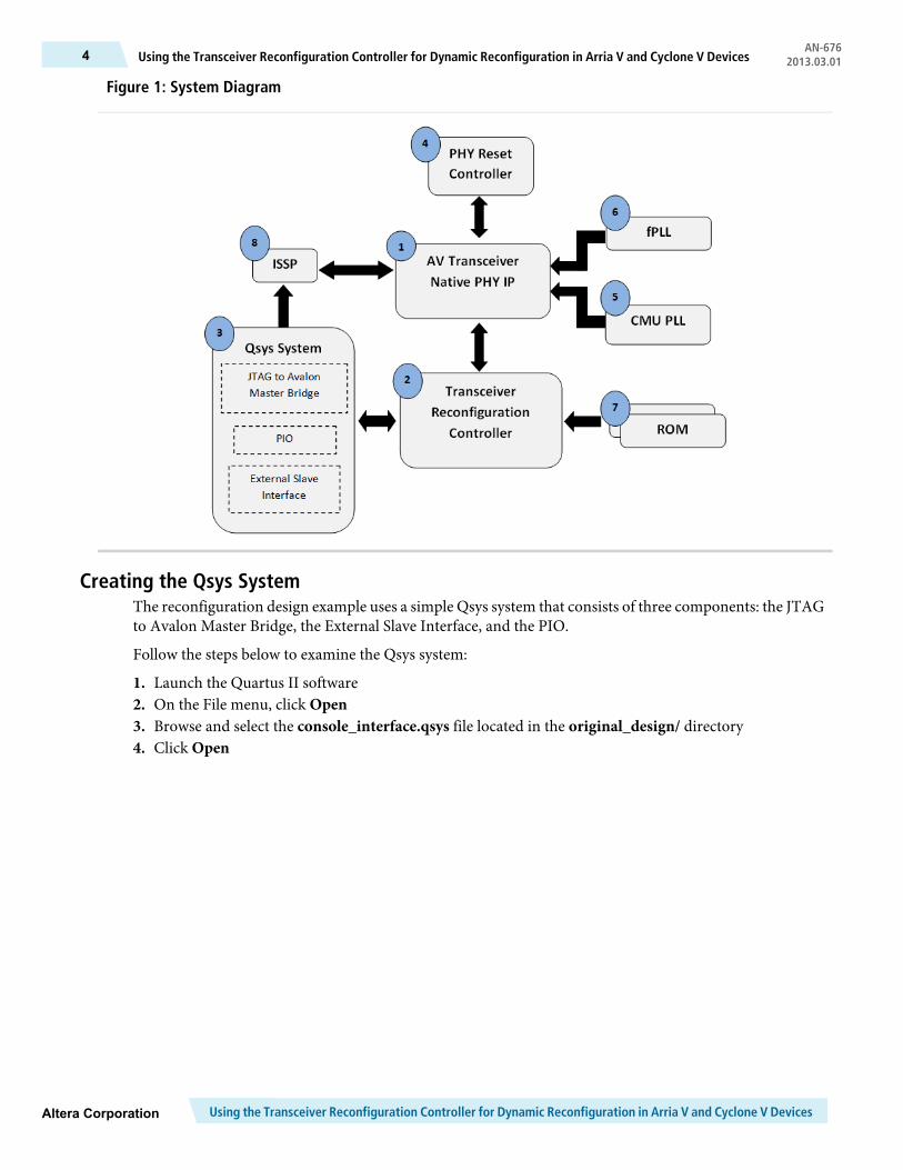
Figure 1: System Diagram
Creating the Qsys SystemThe reconfiguration design example uses a simple Qsys system that consists of three components: the JTAGto Avalon Master Bridge, the External Slave Interface, and the PIO.
Follow the steps below to examine the Qsys system:
1. Launch the Quartus II software2. On the File menu, click Open3. Browse and select the console_interface.qsys file located in the original_design/ directory4. Click Open
Using the Transceiver Reconfiguration Controller for Dynamic Reconfiguration in Arria V and Cyclone V DevicesAltera Corporation
AN-676Using the Transceiver Reconfiguration Controller for Dynamic Reconfiguration in Arria V and Cyclone V Devices4 2013.03.01
The Qsys System ComponentsThe Qsys tool launches and shows all components used.
The Qsys system contains the following components:
• The JTAG toAvalonMaster Bridge component acts as themaster in the design example and is themaincommunication channel between the System Console tool and the external slave interface in the design.The System Console tool issues Avalon reads and writes to the Reconfiguration Controller to carry outreconfiguration of the PHY IP.
• The External Slave Interface component exports all required Avalon signals to the top-level design.With the Avalon signals exported, the Qsys system can interface with any Avalon-compliant componentthat resides outside of the Qsys component library.
• TheTransceiverReconfigurationController is anAvalon-compliant component. Therefore, the ExternalSlave Interface component must be connected to the JTAG to Avalon Master Bridge.
• The PIO component uses external input as control bits in the system. In this design example, the PIOis connected to the rate_select port, which is used to trigger the rate change of the channel from2500 Mbps to 5000 Mbps. The PIO connects to the JTAG to Avalon Master Bridge. You can also connectany PIO to status bits to be monitored externally.
The Arria V and Cyclone V PHY IP components are not supported in the Qsys tool in the QuartusII software. To interface with an Arria V or Cyclone V PHY IP in a Qsys system, you must use anexternal slave interface.
Note:
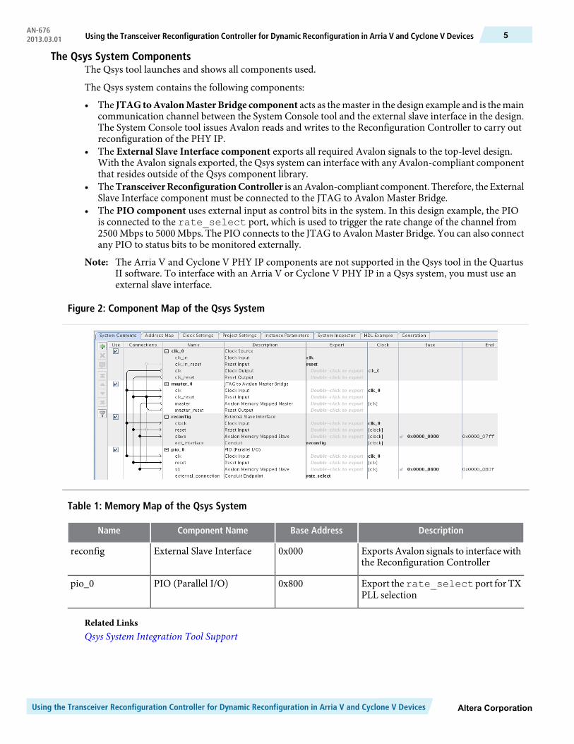
Figure 2: Component Map of the Qsys System
Table 1: Memory Map of the Qsys System
DescriptionBase AddressComponent NameName
Exports Avalon signals to interfacewiththe Reconfiguration Controller
0x000External Slave Interfacereconfig
Export therate_select port for TXPLL selection
0x800PIO (Parallel I/O)pio_0
Related LinksQsys System Integration Tool Support
Altera CorporationUsing the Transceiver Reconfiguration Controller for Dynamic Reconfiguration in Arria V and Cyclone V Devices
5Using the Transceiver Reconfiguration Controller for Dynamic Reconfiguration in Arria V and Cyclone V DevicesAN-6762013.03.01
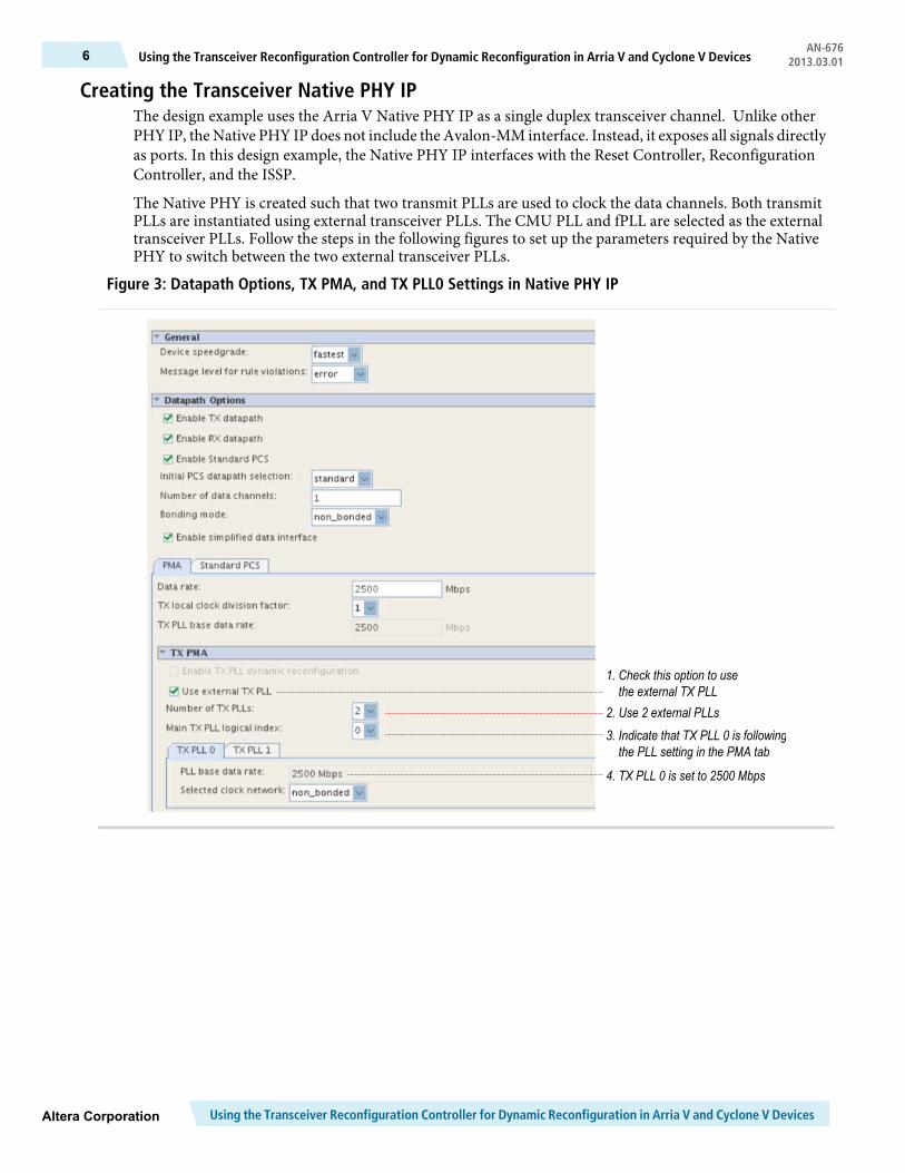
Creating the Transceiver Native PHY IPThe design example uses the Arria V Native PHY IP as a single duplex transceiver channel. Unlike otherPHY IP, the Native PHY IP does not include the Avalon-MM interface. Instead, it exposes all signals directlyas ports. In this design example, the Native PHY IP interfaces with the Reset Controller, ReconfigurationController, and the ISSP.
The Native PHY is created such that two transmit PLLs are used to clock the data channels. Both transmitPLLs are instantiated using external transceiver PLLs. The CMU PLL and fPLL are selected as the externaltransceiver PLLs. Follow the steps in the following figures to set up the parameters required by the NativePHY to switch between the two external transceiver PLLs.
Figure 3: Datapath Options, TX PMA, and TX PLL0 Settings in Native PHY IP
1. Check this option to usethe external TX PLL
2. Use 2 external PLLs3. Indicate that TX PLL 0 is following
the PLL setting in the PMA tab
4. TX PLL 0 is set to 2500 Mbps
Using the Transceiver Reconfiguration Controller for Dynamic Reconfiguration in Arria V and Cyclone V DevicesAltera Corporation
AN-676Using the Transceiver Reconfiguration Controller for Dynamic Reconfiguration in Arria V and Cyclone V Devices6 2013.03.01
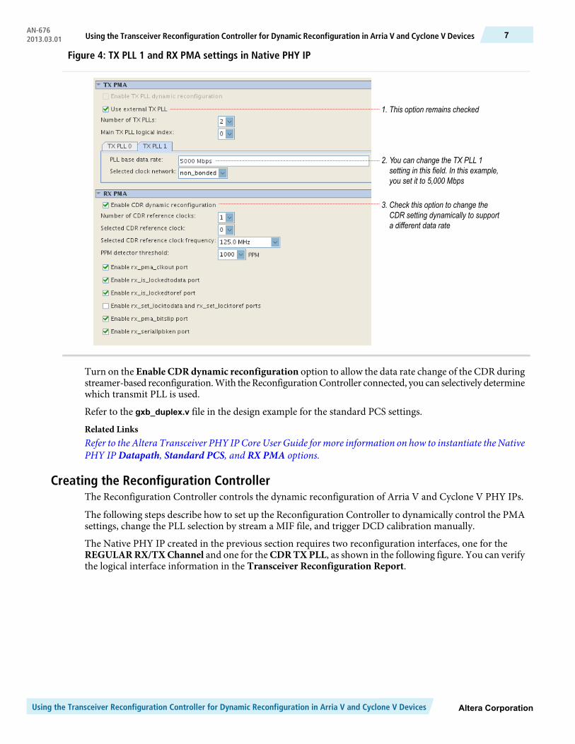
Figure 4: TX PLL 1 and RX PMA settings in Native PHY IP
1. This option remains checked
2. You can change the TX PLL 1setting in this field. In this example,you set it to 5,000 Mbps
3. Check this option to change theCDR setting dynamically to supporta different data rate
Turn on the Enable CDRdynamic reconfiguration option to allow the data rate change of the CDR duringstreamer-based reconfiguration.With theReconfigurationController connected, you can selectively determinewhich transmit PLL is used.
Refer to the gxb_duplex.v file in the design example for the standard PCS settings.
Related LinksRefer to the Altera Transceiver PHY IP Core User Guide formore information on how to instantiate the NativePHY IP Datapath, Standard PCS, and RX PMA options.
Creating the Reconfiguration ControllerThe Reconfiguration Controller controls the dynamic reconfiguration of Arria V and Cyclone V PHY IPs.
The following steps describe how to set up the Reconfiguration Controller to dynamically control the PMAsettings, change the PLL selection by stream a MIF file, and trigger DCD calibration manually.
The Native PHY IP created in the previous section requires two reconfiguration interfaces, one for theREGULARRX/TXChannel and one for the CDRTXPLL, as shown in the following figure. You can verifythe logical interface information in the Transceiver Reconfiguration Report.
Altera CorporationUsing the Transceiver Reconfiguration Controller for Dynamic Reconfiguration in Arria V and Cyclone V Devices
7Using the Transceiver Reconfiguration Controller for Dynamic Reconfiguration in Arria V and Cyclone V DevicesAN-6762013.03.01
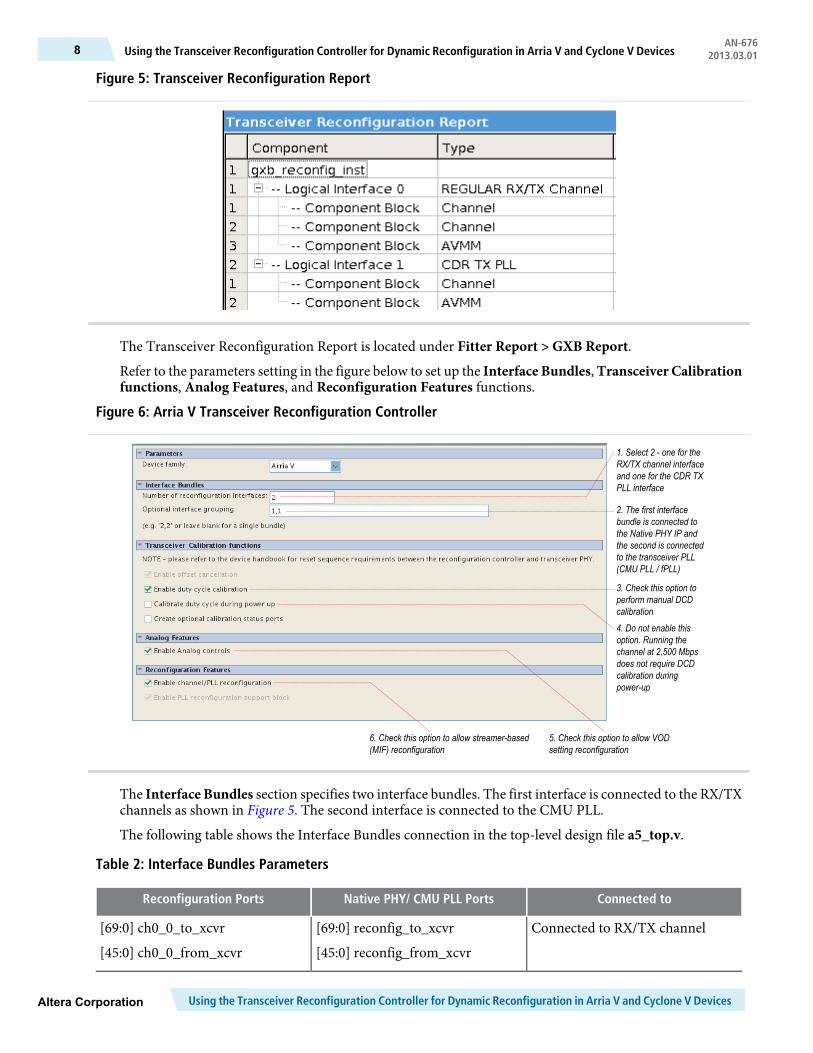
Figure 5: Transceiver Reconfiguration Report
The Transceiver Reconfiguration Report is located under Fitter Report > GXB Report.
Refer to the parameters setting in the figure below to set up the Interface Bundles,Transceiver Calibrationfunctions, Analog Features, and Reconfiguration Features functions.
Figure 6: Arria V Transceiver Reconfiguration Controller
1. Select 2 - one for theRX/TX channel interfaceand one for the CDR TXPLL interface
2. The first interfacebundle is connected tothe Native PHY IP andthe second is connectedto the transceiver PLL(CMU PLL / fPLL)
3. Check this option toperform manual DCDcalibration4. Do not enable thisoption. Running thechannel at 2,500 Mbpsdoes not require DCDcalibration duringpower-up
5. Check this option to allow VODsetting reconfiguration
6. Check this option to allow streamer-based(MIF) reconfiguration
The Interface Bundles section specifies two interface bundles. The first interface is connected to the RX/TXchannels as shown in Figure 5. The second interface is connected to the CMU PLL.
The following table shows the Interface Bundles connection in the top-level design file a5_top.v.
Table 2: Interface Bundles Parameters
Connected toNative PHY/ CMU PLL PortsReconfiguration Ports
Connected to RX/TX channel[69:0] reconfig_to_xcvr
[45:0] reconfig_from_xcvr
[69:0] ch0_0_to_xcvr
[45:0] ch0_0_from_xcvr
Using the Transceiver Reconfiguration Controller for Dynamic Reconfiguration in Arria V and Cyclone V DevicesAltera Corporation
AN-676Using the Transceiver Reconfiguration Controller for Dynamic Reconfiguration in Arria V and Cyclone V Devices8 2013.03.01
Connected toNative PHY/ CMU PLL PortsReconfiguration Ports
Connected to CMU PLL[69:0] reconfig_to_cmu
[45:0] reconfig_from_cmu
[69:0] ch1_1_to_xcvr
[45:0] ch1_1_from_xcvr
In the Transceiver Calibration Functions section, turn on the Enable duty cycle calibration option.
In the Analog Features section, turn on the Enable Analog controls option to enable VOD settingreconfiguration.
In the Reconfiguration Features section, turn on the Enable channel/PLL reconfiguration option to allowthe streamer-based reconfiguration process. This reconfiguration mode reconfigures the TX/RX data path,CDR settings, and TX PLL selection.
After all parameters have been specified, you can generate the Reconfiguration Controller.
Related LinksDuty Cycle Distortion Calibration on page 16Duty Cycle Distortion (DCD) calibration is used to calibrate the TX duty cycle to compensate for the skewintroduced by different clock networks.
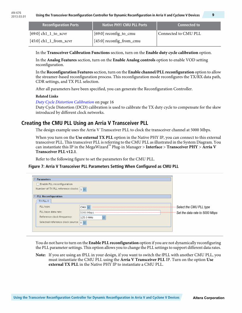
Creating the CMU PLL Using an Arria V Transceiver PLLThe design example uses the Arria V Transceiver PLL to clock the transceiver channel at 5000 Mbps.
When you turn on the Use external TX PLL option in the Native PHY IP, you can connect to this externaltransceiver PLL. This transceiver PLL is referring to the CMU PLL as illustrated in the System Diagram. Youcan instantiate this IP in the MegaWizard™ Plug-in Manager > Interface > Transceiver PHY > Arria VTransceiver PLL v12.1.
Refer to the following figure to set the parameters for the CMU PLL.
Figure 7: Arria V Transceiver PLL Parameters Setting When Configured as CMU PLL
Select the CMU PLL typeSet the data rate to 5000 Mbps
You do not have to turn on theEnable PLL reconfiguration option if you are not dynamically reconfiguringthe PLL parameter settings. This option allows you to change the PLL settings to support different data rates.
If you are using an fPLL in your design, if you want to switch the fPLL with another CMU PLL, youmust instantiate the CMU PLL using the Arria V Transceiver PLL IP. Turn on the option Useexternal TX PLL in the Native PHY IP to instantiate a CMU PLL.
Note:
Altera CorporationUsing the Transceiver Reconfiguration Controller for Dynamic Reconfiguration in Arria V and Cyclone V Devices
9Using the Transceiver Reconfiguration Controller for Dynamic Reconfiguration in Arria V and Cyclone V DevicesAN-6762013.03.01
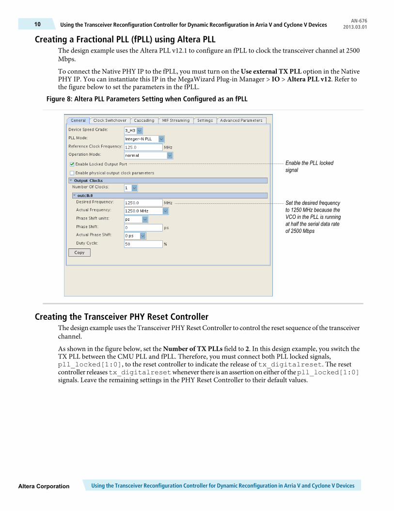
Creating a Fractional PLL (fPLL) using Altera PLLThe design example uses the Altera PLL v12.1 to configure an fPLL to clock the transceiver channel at 2500Mbps.
To connect the Native PHY IP to the fPLL, you must turn on the Use external TX PLL option in the NativePHY IP. You can instantiate this IP in the MegaWizard Plug-in Manager > IO > Altera PLL v12. Refer tothe figure below to set the parameters in the fPLL.
Figure 8: Altera PLL Parameters Setting when Configured as an fPLL
Enable the PLL lockedsignal
Set the desired frequencyto 1250 MHz because theVCO in the PLL is runningat half the serial data rateof 2500 Mbps
Creating the Transceiver PHY Reset ControllerThe design example uses the Transceiver PHYReset Controller to control the reset sequence of the transceiverchannel.
As shown in the figure below, set the Number of TX PLLs field to 2. In this design example, you switch theTX PLL between the CMU PLL and fPLL. Therefore, you must connect both PLL locked signals,pll_locked[1:0], to the reset controller to indicate the release of tx_digitalreset. The resetcontroller releasestx_digitalresetwhenever there is an assertion on either of thepll_locked[1:0]signals. Leave the remaining settings in the PHY Reset Controller to their default values.
Using the Transceiver Reconfiguration Controller for Dynamic Reconfiguration in Arria V and Cyclone V DevicesAltera Corporation
AN-676Using the Transceiver Reconfiguration Controller for Dynamic Reconfiguration in Arria V and Cyclone V Devices10 2013.03.01
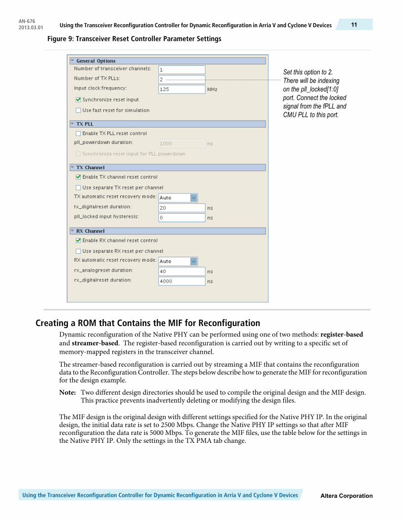
Figure 9: Transceiver Reset Controller Parameter Settings
Set this option to 2.There will be indexingon the pll_locked[1:0]port. Connect the lockedsignal from the fPLL andCMU PLL to this port.
Creating a ROM that Contains the MIF for ReconfigurationDynamic reconfiguration of the Native PHY can be performed using one of two methods: register-basedand streamer-based. The register-based reconfiguration is carried out by writing to a specific set ofmemory-mapped registers in the transceiver channel.
The streamer-based reconfiguration is carried out by streaming a MIF that contains the reconfigurationdata to the ReconfigurationController. The steps below describe how to generate theMIF for reconfigurationfor the design example.
Two different design directories should be used to compile the original design and the MIF design.This practice prevents inadvertently deleting or modifying the design files.
Note:
The MIF design is the original design with different settings specified for the Native PHY IP. In the originaldesign, the initial data rate is set to 2500 Mbps. Change the Native PHY IP settings so that after MIFreconfiguration the data rate is 5000 Mbps. To generate the MIF files, use the table below for the settings inthe Native PHY IP. Only the settings in the TX PMA tab change.
Altera CorporationUsing the Transceiver Reconfiguration Controller for Dynamic Reconfiguration in Arria V and Cyclone V Devices
11Using the Transceiver Reconfiguration Controller for Dynamic Reconfiguration in Arria V and Cyclone V DevicesAN-6762013.03.01
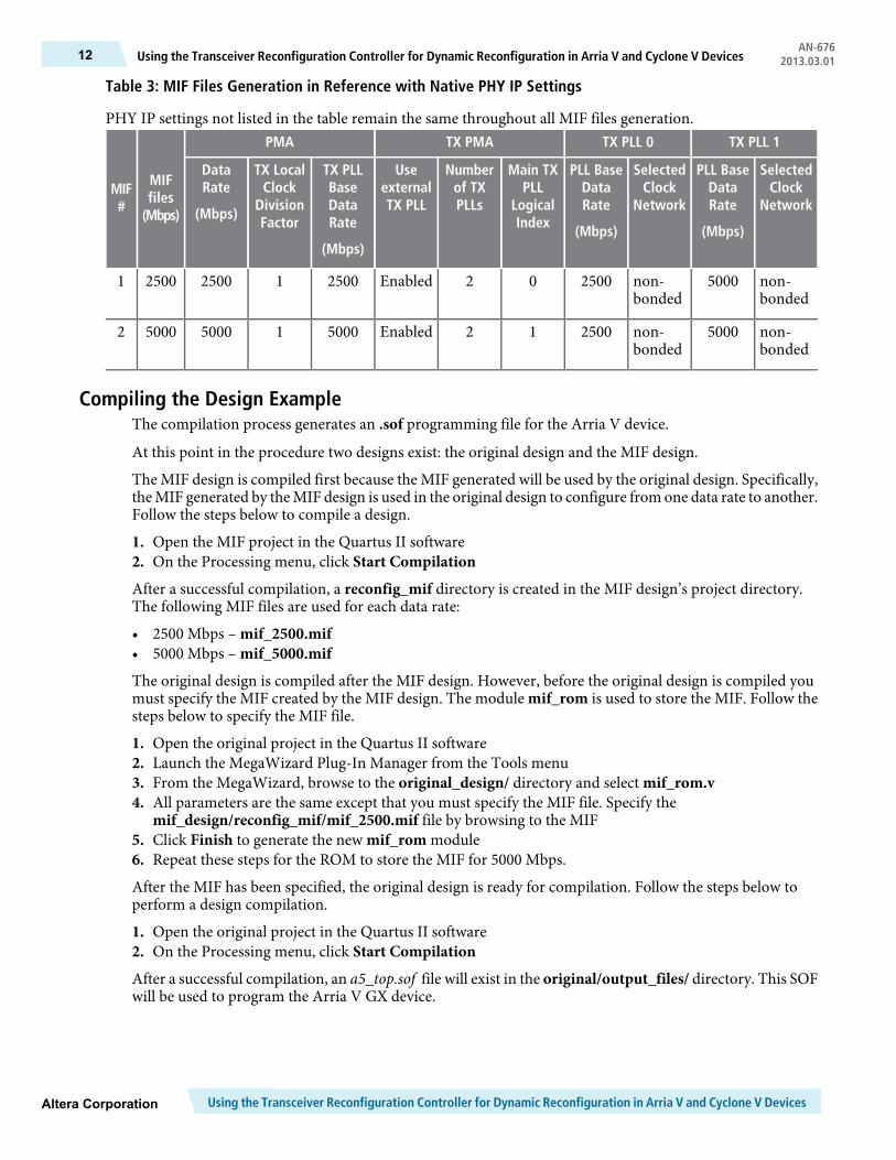
Table 3: MIF Files Generation in Reference with Native PHY IP Settings
PHY IP settings not listed in the table remain the same throughout all MIF files generation.TX PLL 1TX PLL 0TX PMAPMA
MIFfiles
(Mbps)
MIF#
SelectedClock
Network
PLL BaseDataRate
(Mbps)
SelectedClock
Network
PLL BaseDataRate
(Mbps)
Main TXPLL
LogicalIndex
Numberof TXPLLs
UseexternalTX PLL
TX PLLBaseDataRate
(Mbps)
TX LocalClock
DivisionFactor
DataRate
(Mbps)
non-bonded
5000non-bonded
250002Enabled25001250025001
non-bonded
5000non-bonded
250012Enabled50001500050002
Compiling the Design ExampleThe compilation process generates an .sof programming file for the Arria V device.
At this point in the procedure two designs exist: the original design and the MIF design.
The MIF design is compiled first because the MIF generated will be used by the original design. Specifically,theMIF generated by theMIF design is used in the original design to configure fromone data rate to another.Follow the steps below to compile a design.
1. Open the MIF project in the Quartus II software2. On the Processing menu, click Start Compilation
After a successful compilation, a reconfig_mif directory is created in the MIF design’s project directory.The following MIF files are used for each data rate:
• 2500 Mbps – mif_2500.mif• 5000 Mbps – mif_5000.mif
The original design is compiled after the MIF design. However, before the original design is compiled youmust specify the MIF created by the MIF design. The module mif_rom is used to store the MIF. Follow thesteps below to specify the MIF file.
1. Open the original project in the Quartus II software2. Launch the MegaWizard Plug-In Manager from the Tools menu3. From the MegaWizard, browse to the original_design/ directory and select mif_rom.v4. All parameters are the same except that you must specify the MIF file. Specify the
mif_design/reconfig_mif/mif_2500.mif file by browsing to the MIF5. Click Finish to generate the new mif_rom module6. Repeat these steps for the ROM to store the MIF for 5000 Mbps.
After the MIF has been specified, the original design is ready for compilation. Follow the steps below toperform a design compilation.
1. Open the original project in the Quartus II software2. On the Processing menu, click Start Compilation
After a successful compilation, an a5_top.sof file will exist in the original/output_files/ directory. This SOFwill be used to program the Arria V GX device.
Using the Transceiver Reconfiguration Controller for Dynamic Reconfiguration in Arria V and Cyclone V DevicesAltera Corporation
AN-676Using the Transceiver Reconfiguration Controller for Dynamic Reconfiguration in Arria V and Cyclone V Devices12 2013.03.01
Creating In-System Sources and Probes (ISSP)The ISSP is instantiated to control the PHY reset, enable serial loopback, and align word boundaries onreceived data.
The Qsys system communicates with the ISSP to control the Native PHY.
Table 4: ISSP and Its Control in the Design Example
DescriptionISSPBit
Aligns theword boundaries inmanual alignmentmoderx_std_wa_patternalign[2]
Enables the serial loopback of the transceiver channelrx_seriallpbken[1]
Used as a system resethssi_reset[0]
Performing Reconfiguration with the System Console ToolWith the Avalon to JTAG Master Bridge, reconfiguration commands are directly streamed to theReconfiguration Controller through the JTAG port. The System Console tool issues commands to initiatedynamic reconfiguration of the Native PHY IP.
This design example uses a Tcl script called main.tcl that consists of several different procedures withdifferent functionality.
Program the Arria V GX device with the SOF generated in the previous section before launching theSystem Console. Having both the programmer and System Console open simultaneously can causeprogramming errors.
Note:
Before any reconfiguration can take place, you must first launch the System Console tool. To launch theSystem Console, perform the following steps:
1. Program the Arria V Device with the SOF generated from the original design2. Launch the Quartus II software3. From the Quartus II software, on the Tools menu, click Qsys4. From the Qsys tool, on the Tools menu, click System Console5. Ensure that the present working directory contains main.tcl
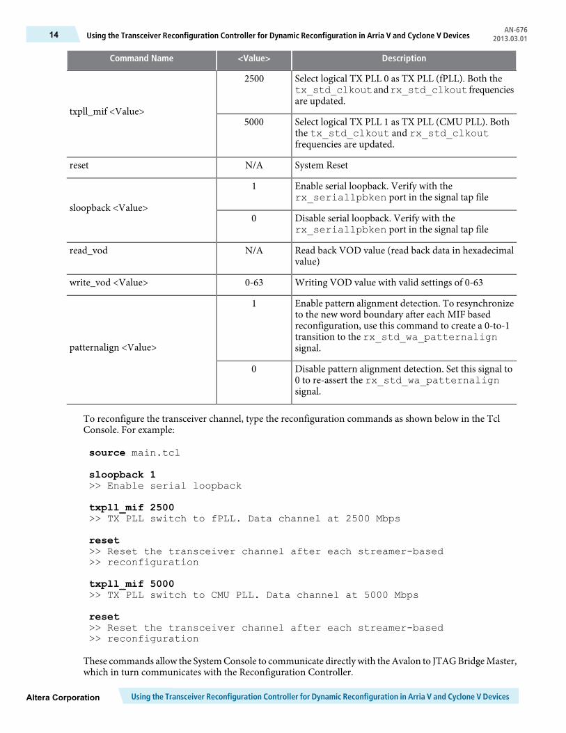
The following table lists the procedures in main.tcl. You can type in a procedure name and its value toexecute the reconfiguration process. Verify your results with the signal tap file (stp1.stp) by looking at thesignals listed in the following table.
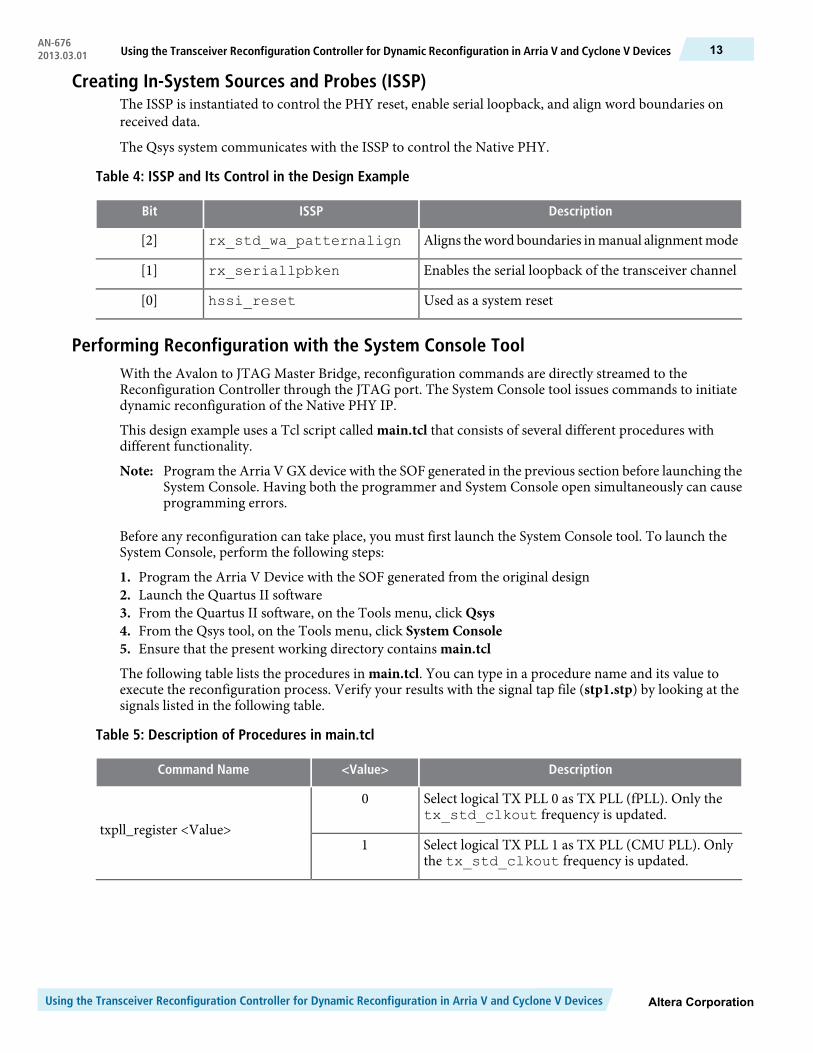
Table 5: Description of Procedures in main.tcl
Description<Value>Command Name
Select logical TX PLL 0 as TX PLL (fPLL). Only thetx_std_clkout frequency is updated.
0
txpll_register <Value>Select logical TX PLL 1 as TX PLL (CMU PLL). Onlythe tx_std_clkout frequency is updated.
1
Altera CorporationUsing the Transceiver Reconfiguration Controller for Dynamic Reconfiguration in Arria V and Cyclone V Devices
13Using the Transceiver Reconfiguration Controller for Dynamic Reconfiguration in Arria V and Cyclone V DevicesAN-6762013.03.01
Description<Value>Command Name
Select logical TX PLL 0 as TX PLL (fPLL). Both thetx_std_clkoutandrx_std_clkout frequenciesare updated.
2500
txpll_mif <Value>Select logical TX PLL 1 as TX PLL (CMU PLL). Boththe tx_std_clkout and rx_std_clkoutfrequencies are updated.
5000
System ResetN/Areset
Enable serial loopback. Verify with therx_seriallpbken port in the signal tap file
1
sloopback <Value>Disable serial loopback. Verify with therx_seriallpbken port in the signal tap file
0
Read back VOD value (read back data in hexadecimalvalue)
N/Aread_vod
Writing VOD value with valid settings of 0-630-63write_vod <Value>
Enable pattern alignment detection. To resynchronizeto the new word boundary after each MIF basedreconfiguration, use this command to create a 0-to-1transition to the rx_std_wa_patternalignsignal.
1
patternalign <Value>
Disable pattern alignment detection. Set this signal to0 to re-assert the rx_std_wa_patternalignsignal.
0
To reconfigure the transceiver channel, type the reconfiguration commands as shown below in the TclConsole. For example:
source main.tcl
sloopback 1>> Enable serial loopback
txpll_mif 2500>> TX PLL switch to fPLL. Data channel at 2500 Mbps
reset>> Reset the transceiver channel after each streamer-based>> reconfiguration
txpll_mif 5000>> TX PLL switch to CMU PLL. Data channel at 5000 Mbps
reset>> Reset the transceiver channel after each streamer-based>> reconfiguration
These commands allow the SystemConsole to communicate directly with theAvalon to JTAGBridgeMaster,which in turn communicates with the Reconfiguration Controller.
Using the Transceiver Reconfiguration Controller for Dynamic Reconfiguration in Arria V and Cyclone V DevicesAltera Corporation
AN-676Using the Transceiver Reconfiguration Controller for Dynamic Reconfiguration in Arria V and Cyclone V Devices14 2013.03.01
Related LinksAnalyzing and Debugging Designs with the System ConsoleRefer to the Altera Transceiver PHY IP Core User Guide for more information on the specific address mapassociated with the Reconfiguration Controller
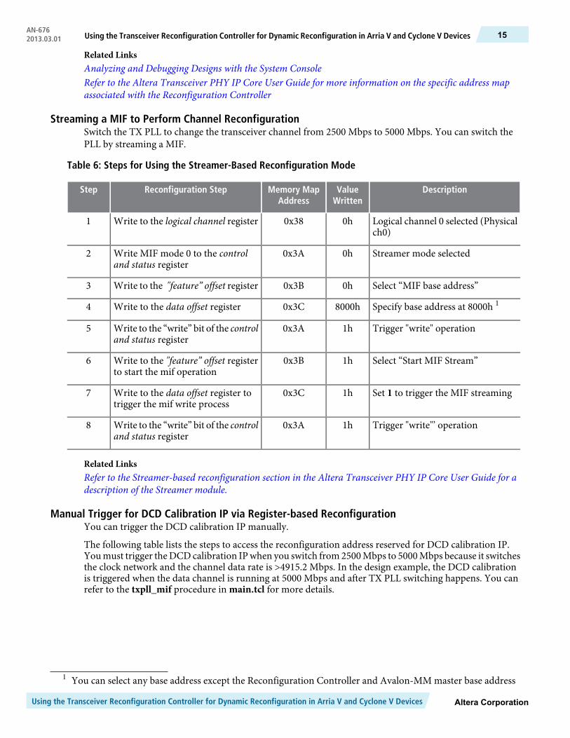
Streaming a MIF to Perform Channel ReconfigurationSwitch the TX PLL to change the transceiver channel from 2500 Mbps to 5000 Mbps. You can switch thePLL by streaming a MIF.
Table 6: Steps for Using the Streamer-Based Reconfiguration Mode
DescriptionValueWritten
Memory MapAddress
Reconfiguration StepStep
Logical channel 0 selected (Physicalch0)
0h0x38Write to the logical channel register1
Streamer mode selected0h0x3AWrite MIF mode 0 to the controland status register
2
Select “MIF base address”0h0x3BWrite to the "feature” offset register3
Specify base address at 8000h 18000h0x3CWrite to the data offset register4
Trigger "write" operation1h0x3AWrite to the “write” bit of the controland status register
5
Select “Start MIF Stream”1h0x3BWrite to the "feature” offset registerto start the mif operation
6
Set 1 to trigger the MIF streaming1h0x3CWrite to the data offset register totrigger the mif write process
7
Trigger "write"’ operation1h0x3AWrite to the “write” bit of the controland status register
8
Related LinksRefer to the Streamer-based reconfiguration section in the Altera Transceiver PHY IP Core User Guide for adescription of the Streamer module.
Manual Trigger for DCD Calibration IP via Register-based ReconfigurationYou can trigger the DCD calibration IP manually.
The following table lists the steps to access the reconfiguration address reserved for DCD calibration IP.Youmust trigger theDCDcalibration IPwhen you switch from2500Mbps to 5000Mbps because it switchesthe clock network and the channel data rate is >4915.2 Mbps. In the design example, the DCD calibrationis triggered when the data channel is running at 5000 Mbps and after TX PLL switching happens. You canrefer to the txpll_mif procedure in main.tcl for more details.
1 You can select any base address except the Reconfiguration Controller and Avalon-MM master base address
Altera CorporationUsing the Transceiver Reconfiguration Controller for Dynamic Reconfiguration in Arria V and Cyclone V Devices
15Using the Transceiver Reconfiguration Controller for Dynamic Reconfiguration in Arria V and Cyclone V DevicesAN-6762013.03.01
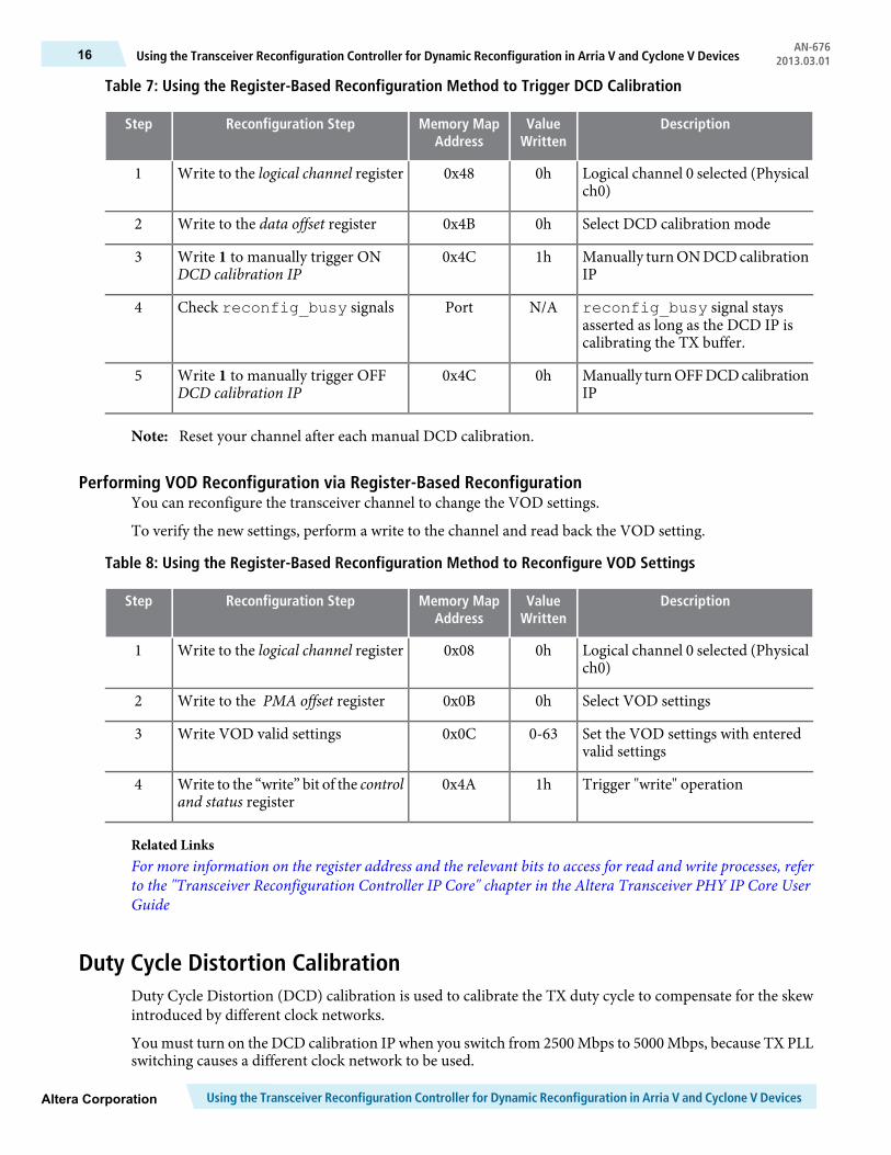
Table 7: Using the Register-Based Reconfiguration Method to Trigger DCD Calibration
DescriptionValueWritten
Memory MapAddress
Reconfiguration StepStep
Logical channel 0 selected (Physicalch0)
0h0x48Write to the logical channel register1
Select DCD calibration mode0h0x4BWrite to the data offset register2
Manually turnONDCDcalibrationIP
1h0x4CWrite 1 to manually trigger ONDCD calibration IP
3
reconfig_busy signal staysasserted as long as the DCD IP iscalibrating the TX buffer.
N/APortCheck reconfig_busy signals4
Manually turnOFFDCDcalibrationIP
0h0x4CWrite 1 to manually trigger OFFDCD calibration IP
5
Reset your channel after each manual DCD calibration.Note:
Performing VOD Reconfiguration via Register-Based ReconfigurationYou can reconfigure the transceiver channel to change the VOD settings.
To verify the new settings, perform a write to the channel and read back the VOD setting.
Table 8: Using the Register-Based Reconfiguration Method to Reconfigure VOD Settings
DescriptionValueWritten
Memory MapAddress
Reconfiguration StepStep
Logical channel 0 selected (Physicalch0)
0h0x08Write to the logical channel register1
Select VOD settings0h0x0BWrite to the PMA offset register2
Set the VOD settings with enteredvalid settings
0-630x0CWrite VOD valid settings3
Trigger "write" operation1h0x4AWrite to the “write” bit of the controland status register
4
Related LinksFor more information on the register address and the relevant bits to access for read and write processes, referto the "Transceiver Reconfiguration Controller IP Core" chapter in the Altera Transceiver PHY IP Core UserGuide
Duty Cycle Distortion CalibrationDuty Cycle Distortion (DCD) calibration is used to calibrate the TX duty cycle to compensate for the skewintroduced by different clock networks.
You must turn on the DCD calibration IP when you switch from 2500 Mbps to 5000 Mbps, because TX PLLswitching causes a different clock network to be used.
Using the Transceiver Reconfiguration Controller for Dynamic Reconfiguration in Arria V and Cyclone V DevicesAltera Corporation
AN-676Using the Transceiver Reconfiguration Controller for Dynamic Reconfiguration in Arria V and Cyclone V Devices16 2013.03.01
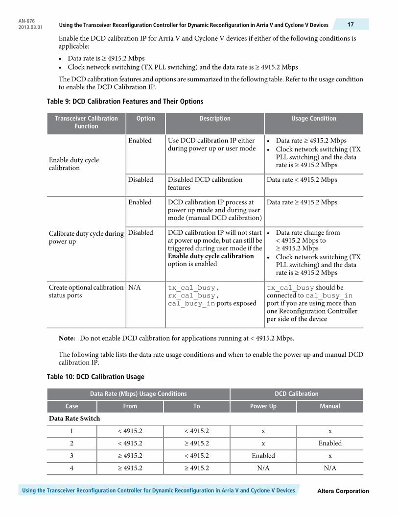
Enable the DCD calibration IP for Arria V and Cyclone V devices if either of the following conditions isapplicable:
• Data rate is ≥ 4915.2 Mbps• Clock network switching (TX PLL switching) and the data rate is ≥ 4915.2 Mbps
TheDCDcalibration features and options are summarized in the following table. Refer to the usage conditionto enable the DCD Calibration IP.
Table 9: DCD Calibration Features and Their Options
Usage ConditionDescriptionOptionTransceiver CalibrationFunction
• Data rate ≥ 4915.2 Mbps• Clock network switching (TX
PLL switching) and the datarate is ≥ 4915.2 Mbps
Use DCD calibration IP eitherduring power up or user mode
Enabled
Enable duty cyclecalibration
Data rate < 4915.2 MbpsDisabled DCD calibrationfeatures
Disabled
Data rate ≥ 4915.2 MbpsDCD calibration IP process atpower up mode and during usermode (manual DCD calibration)
Enabled
Calibrate duty cycle duringpower up
• Data rate change from< 4915.2 Mbps to≥ 4915.2 Mbps
• Clock network switching (TXPLL switching) and the datarate is ≥ 4915.2 Mbps
DCD calibration IP will not startat power up mode, but can still betriggered during user mode if theEnable duty cycle calibrationoption is enabled
Disabled
tx_cal_busy should beconnected to cal_busy_inport if you are using more thanone Reconfiguration Controllerper side of the device
tx_cal_busy ,rx_cal_busy ,cal_busy_in ports exposed
N/ACreate optional calibrationstatus ports
Do not enable DCD calibration for applications running at < 4915.2 Mbps.Note:
The following table lists the data rate usage conditions and when to enable the power up and manual DCDcalibration IP.
Table 10: DCD Calibration Usage
DCD CalibrationData Rate (Mbps) Usage Conditions
ManualPower UpToFromCase
Data Rate Switch
xx< 4915.2< 4915.21
Enabledx≥ 4915.2< 4915.22
xEnabled< 4915.2≥ 4915.23
N/AN/A≥ 4915.2≥ 4915.24
Altera CorporationUsing the Transceiver Reconfiguration Controller for Dynamic Reconfiguration in Arria V and Cyclone V Devices
17Using the Transceiver Reconfiguration Controller for Dynamic Reconfiguration in Arria V and Cyclone V DevicesAN-6762013.03.01
DCD CalibrationData Rate (Mbps) Usage Conditions
ManualPower UpToFromCase
EnabledEnabled9830.46144Example 1
xEnabled61449830.4Example 2
Clock Network Switch (TX PLL Switching)
xx< 4915.2< 4915.21
Enabledx≥ 4915.2< 4915.22
xEnabled< 4915.2≥ 4915.23
EnabledEnabled≥ 4915.2≥ 4915.24
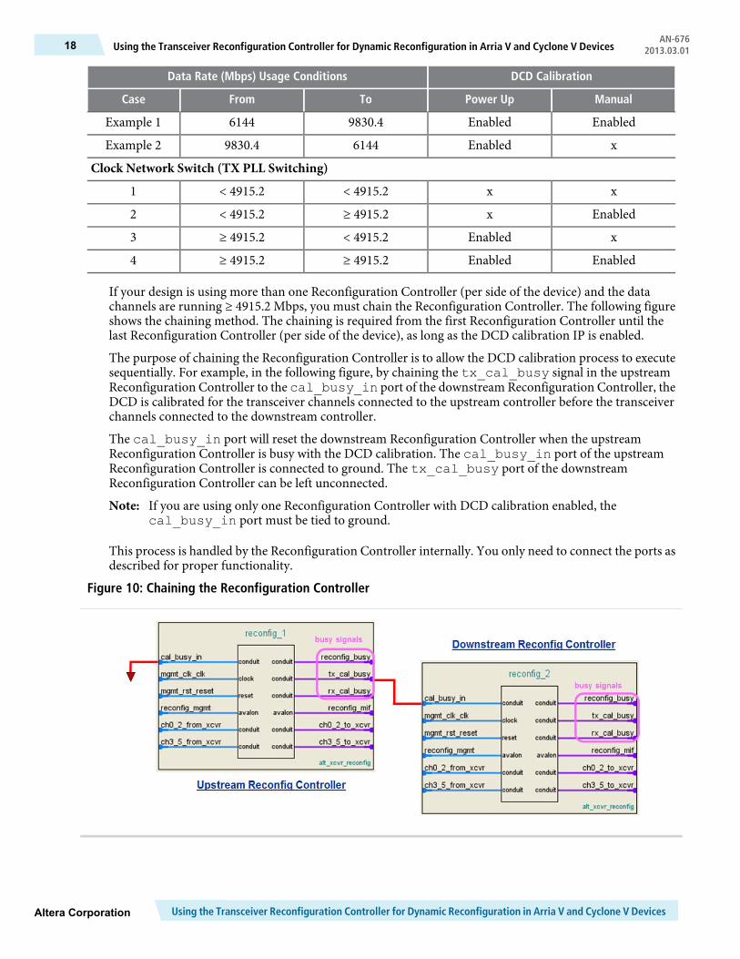
If your design is using more than one Reconfiguration Controller (per side of the device) and the datachannels are running ≥ 4915.2 Mbps, you must chain the Reconfiguration Controller. The following figureshows the chaining method. The chaining is required from the first Reconfiguration Controller until thelast Reconfiguration Controller (per side of the device), as long as the DCD calibration IP is enabled.
The purpose of chaining the Reconfiguration Controller is to allow the DCD calibration process to executesequentially. For example, in the following figure, by chaining the tx_cal_busy signal in the upstreamReconfiguration Controller to the cal_busy_in port of the downstream Reconfiguration Controller, theDCD is calibrated for the transceiver channels connected to the upstream controller before the transceiverchannels connected to the downstream controller.
The cal_busy_in port will reset the downstream Reconfiguration Controller when the upstreamReconfiguration Controller is busy with the DCD calibration. The cal_busy_in port of the upstreamReconfiguration Controller is connected to ground. The tx_cal_busy port of the downstreamReconfiguration Controller can be left unconnected.
If you are using only one Reconfiguration Controller with DCD calibration enabled, thecal_busy_in port must be tied to ground.
Note:
This process is handled by the Reconfiguration Controller internally. You only need to connect the ports asdescribed for proper functionality.
Figure 10: Chaining the Reconfiguration Controller
Using the Transceiver Reconfiguration Controller for Dynamic Reconfiguration in Arria V and Cyclone V DevicesAltera Corporation
AN-676Using the Transceiver Reconfiguration Controller for Dynamic Reconfiguration in Arria V and Cyclone V Devices18 2013.03.01
As this design example demonstrates, the Reconfiguration Controller provides an easy and efficient methodto dynamically change the Arria V GX Native PHY IP's settings, including TX PLL switching, VOD settingupdates, and triggering the DCD calibration process during user mode.
Document Revision History
Table 11: Document Revision History
ChangesVersionDate
Initial release.2013.03.01March 2013
Altera CorporationUsing the Transceiver Reconfiguration Controller for Dynamic Reconfiguration in Arria V and Cyclone V Devices
19Using the Transceiver Reconfiguration Controller for Dynamic Reconfiguration in Arria V and Cyclone V DevicesAN-6762013.03.01