Embed Size (px)
Citation preview

Usko Anttikoski Memo 14 September 2007
Fixed transport connections across the Baltic fromFinland to Sweden and Estonia.
Preliminary feasibility assessment.
2(29)
Usko Anttikoski Memo 14 September 2007
Fixed traffic connections across the Baltic from Finlandto Sweden and Estonia.
Preliminary feasibility assessment.
Summary
Below is an explanation of the possibility of constructing fixed rail connections via undersea tunnels between Finland and Sweden, and Finland and Estonia. The connection viathe Åland Islands includes railway tunnels under the Finnish Archipelago Sea and theÅland Sea, between Turku in Finland and Uppsala in Sweden. This assessment will alsodeal with the Gulf of Finland railway tunnel linking Helsinki and Tallinn in Estonia, as wellas the railway tunnel under Kvarken (Merenkurkku in Finnish, the narrowest section of theGulf of Bothnia), linking Vaasa in Finland with Umeå in Sweden.
Railway routes on nautical maps, longitudinal profiles and proposals for tunnel crosssections will also be presented in this memo. The length of the railway lines across theBaltic range between 88 and 240 km. The length of individual tunnels dug into the rockunder the sea range between 60 and 85 km. In the case of the railway tunnels, the construction cost of the connection across the Åland Islands will total between EUR 3.4 and5.0 billion, across the Gulf of Finland between EUR 2.3 and 2.7 billion and across Kvarkenbetween EUR 1.7 and 2.1 billion. The bridge option in the Åland Islands would add EUR2.0 to 3.0 billion to the costs. The construction costs quoted are according to 2007 pricelevels. The construction time needed for the connections would vary between 15 and 30years.
This assessment particularly concerns rock tunnels and the construction of the foundationsof surface connections. Land use and transport plans have not been discussed. This assessment is expected to generate interest in fixed transport connections across the seaand in the research and development of offshore technology in the northern part of theBaltic, in the bedrock of the Fennoscandian Shield.

3(29)
Contents:
1. Introduction 32. Background and events 43. Unit costs 74. Undersea tunnel technology 95. Åland Sea Tunnel 126. Åland Sea Embankment 127. Åland Sea Ferry 128. Archipelago Sea tunnel 139. Archipelago Sea embankment 1310. Gulf of Finland tunnel 1511. Kvarken tunnel 1712. Summary of construction costs 1713. Comments concerning financing 1814. Final conclusions 1915. Suggestions for actions 1916. Appendices 20
1. Introduction
This memo deals with undersea rock tunnels and the construction of the foundations ofsurface connections. The tunnel and embankment connections in the Åland Sea and in theFinnish Archipelago Sea have been included for the first time. The railway tunnels acrossthe Gulf of Finland and Kvarken have been dealt with before.
The study has been conducted for 15 years through voluntary work by various societies. Itis hoped that it will generate interest in fixed transport connections across the sea and inthe research and development of offshore technology.
The Fennoscandian bedrock is mostly similar in Finland, Sweden, Norway and RussianKarelia (Geological Map of the Fennoscandian Shield 1:2,000,000. Geological Survey ofFinland, Norway, Sweden and Russia 2001). Based on experiences from numerous construction sites, the bedrock is extremely well suited to the construction of tunnels. In fact, abedrock resource of similar quality can hardly be found anywhere else in the world.
The bedrock in the Åland Sea and the Finnish Archipelago Sea in the region where thetunnels would be constructed is similar to that around the Gulf of Finland and Kvarken tunnels (with the exception of the Estonian coast).
The transport connections are displayed on the Norden map on a scale of 1:2,000,000(cover illustration). The Åland Islands connections are shown on the nautical map of theFinnish Archipelago Sea (1:250,000) and the Gulf of Finland connections on the nauticalmap of the western part of the Gulf of Finland (1:250,000).
The longitudinal profiles of the routes have been drawn on a scale of 1:250,000/1:2,500.The seafloor depth data has been obtained from nautical maps and the ground altitudedata from Google Earth Maps. The rock surface is estimated to be situated at a depth of

4(29)
between 5 and 50 metres from the seabed. In addition, we will present preliminary construction principles and some proposed structural sketches as a basis for discussion.
The proposed railway lines have been made for a preliminary feasibility assessment. Railway lines have not been inserted in the maps in great detail and no negotiations havebeen undertaken with the planning authorities.
2. Background and events
In the early 1990s the Geological Survey of Finland published maps of the Baltic Sea’sgeology, which generated interest in the construction of undersea tunnels from Finland toEstonia and Sweden. As a representative of the Finnish Geotechnical Society, Usko Anttikoski proposed three new tunnels across the Baltic at the Nordic Geotechnical Meeting(NGM92) in Aalborg, Denmark, in 1992. The tunnels were located in the Gulf of Finland,the Åland Islands (Finnish Archipelago Sea and Åland Sea) and Kvarken.
HelsinkiTallinna Seura ry (HelsinkiTallinn Association) published a book entitled HelsinkiTallinna kaksoiskaupunki. Tarua vai totta? (HelsinkiTallinn Twin City. Fact or Myth? –edited by Martti Asunmaa) in Tallinn, Estonia, in 1995. The book also explains the possibility of constructing a railway tunnel across the Gulf of Finland (pp. 100110): U. Anttikoski,V. Castrén and T. Cronvall. HelsinkiTallinn Railway Tunnel, Utopia or Possibility?
Seminars on the construction of the railway tunnel across the Gulf of Finland were organised in 1995 and 1996 with tunnel experts from the Helsinki University of Technology, theTallinn University of Technology and the St Petersburg State Railway University. The participants drew up a joint statement expressing that it would be technically possible to buildan undersea tunnel but the question is primarily a financial one. The project was positivelyreceived in Estonia, Poland and Russia. In Finland, however, it did not receive the backingof the Ministry of Transport and Communications. For this reason, crucial geological surveys and studies from the point of view of transportation economics have not been conducted.
HelsinkiTallinna tunneliyhdistys ry. (HelsinkiTallinn Tunnel Association) – nowadaysBaltirailyhdistys ry, with Martti Asunmaa as its Chairman – conducted a study of the tunnel project entitled Preliminary Project Plan, 9 April 1997. HelsinkiTallinn Railway Tunnel.Shortcut to Europe.
Finland’s tunnel proposals have also been explained at the industry’s meetings and conferences, including U. Anttikoski and A. Vilo: Baltic Sea Circular Link via Rock Tunnels.World Tunnel Congress. Oslo, 29 May – 3 June 1999. “Challenges for the 21st Century.”In addition to the railway tunnel across the Gulf of Finland, the essay presents an evaluation of the Kvarken railway tunnel (illustration 3). Commissioned by The Kvarken Council, surveys on the road connection across Kvarken,between Vaasa and Umeå, were published in 2000. In connection with these, the possibility of constructing a railway tunnel was also evaluated (Fast förbindelse över Kvarken. OyTalentek Ab & Infraplan AB 2000). Newspaper articles have found constructing the tunnela possible option although the project is still not deemed economically viable.

5(29)
Upon request from the Baltirail Association, Usko Anttikoski published an evaluation ofthe possibility of constructing a railway tunnel under the Gulf of Finland on 6 November2001, based on experiences shared at the World Tunnel Congress in Milan. In particular,the four railway tunnel projects under road tunnels in the Alps were discussed at the Milanevent. Of these, the Lötschberg tunnel (34 km) between Italy and Switzerland was completed in the summer of 2007, and the world’s longest railway tunnel, the Gotthard tunnel(57 km), is expected to be completed in 2015. The projects can be viewed on the tunnels’websites, for example at www.alptransit.ch. Over 70% of the Gotthard tunnel has alreadybeen excavated.
The Finnish Rail Administration included the Gulf of Finland railway tunnel project in itsown vision for the year 2050 (Visions of Railway Transport in Southern Finland in 2050,project descriptions 26 March 2004/14).
Upon request from the Board of the Baltirail Association, Usko Anttikoski revised hisevaluation of the feasibility of the Gulf of Finland railway tunnel in a memo dated 22 January 2005 to bring it up to date with the situation in early 2005.
There has been interest in Sweden in a transport connection to Finland via the Åland Islands, and on to Russia. For this reason, Usko Anttikoski studied the possibility of buildinga connection via the Åland Islands in a memo dated 23 November 2006.
On 23 November 2006 the Finnish Geotechnical Society posted two memos on fixedtransport connections to Sweden and Estonia on its website www.sgy.fi under the “news”section on the homepage. One of these (dated 23 November 2006) dealt with the fixedtransport connection via the Åland Islands, while the other (dated 22 January 2005) discussed the Gulf of Finland railway tunnel. A combined memo on these was published on31 January 2007.
This memo, dated 14 September 2007, is an update of the previous memo.

6(29)
Illustration 2. As a representative of the Finnish Geotechnical Society, Usko Anttikoski presented three new tunnels under the Baltic at the Nordic Geotechnical Meeting (NGM92) inAalborg, Denmark, in 1992. The tunnels were located in the Gulf of Finland, the Åland Islands (Finnish Archipelago Sea and Åland Sea) and Kvarken. The geological map by theGeological Survey of Finland (GTK) was used as a basis for the routing of the tunnels.

7(29)
Illustration 3. Circular Link proposal for a highspeed railway connection around the Baltic(Anttikoski and Vilo 1999). Usko Anttikoski’s proposal for a HelsinkiTurkuPoriVaasacoastal railway (2006) has also been included.
3. Unit costs
Plans for railway tunnels and sea embankments should be drawn up for a lifespan of over100 years and for a minimum train speed of 200 km/h.
The Channel Tunnel’s high construction costs labelled undersea traffic tunnels as expensive, particularly in Central Europe. The Channel Tunnel was completed about 15 yearsago as a joint venture between the United Kingdom and France. From the technical pointof view, the construction work proceeded well despite the particularly challenging circumstances. The tunnel has been dubbed the construction project of the century, even thoughit far exceeded its budget.
Tunnelling work in Helsinki (300 km of tunnels, including the world’s longest tunnel, thePäijänne tunnel, measuring 120 km), however, has remained within budget. The underseawaste water discharge tunnel (8 km) leading to the south of Katajaluoto was also completed within its cost estimate. For this reason, the Finnish opinion of tunnelling costsseems to be more confident than elsewhere. The estimation of the costs of constructingundersea tunnels is less reliable because the conditions are not sufficiently known andthere is only limited experience of them.

8(29)
The table below (listing completed railway tunnels and work in progress) uses cost datafrom the memo dated 6 November 2001, with the addition of the details of the general planfor the Greater Helsinki Ring Railway:www.keharata.net/marja_yleissuunnitelmaraportti.pdf.
The expenses include the overall costs of tunnel construction and railway structures andequipment, including their general expenses, excluding value added tax, at 2001 price levels.
Unit costs for finished railway tunnels and for work in progress:Alp tunnels (23 tunnels) 6080 EUR million/kmChannel Tunnel (3 tunnels) 172 ”Railway tunnel at Oslo Airport (2 tracks in 1 tunnel) 13 ”Great Belt railway tunnel (2 tunnels) 69 ”Vuosaari port railway tunnel (1 track) 7 ”Railway tunnel in Marja Railway general plan (2 tunnels) 12 ”Railway tunnels in Marja Railway general plan (including stations) 23 ”Lahti direct railway line (no tunnels) 5 ”Botniabana (25 km of tunnels, 12 tracks) 8 ”Raippaluoto road bridge (1045 m/12 m, span 26 m/250 m) 24 ”Puumalansalmi bridge (781 m/13 m, span 25 m/140 m) 12 ”
Unit costs used, at 2001 price levels:Hard rock tunnel (23 tunnels) 20 ”Soft rock tunnel (e.g. in mainland Estonia) 50 ”Work tunnel 3 ”Maintenance shaft and base on island (”railway lighthouse”) 10 EUR million/eachEmbankment railway (2 tracks, including bridges) 5 EUR million/kmEmbankment road (2 lanes, including bridges) 5 ”Both together 10 ”
Construction costs in special, socalled mega projects are usually projected too low. Thecosts of the Gotthard tunnel have risen by 28% and those of the Vuosaari port railway byabout 30% compared to the estimates presented in the early stages of the projects, eventhough construction plans and ground surveys for these projects were carried out properly.The rise in construction costs is due to changes in the construction business’s trend duringthe longterm projects and other unforeseeable circumstances occurring during the work.For instance, the price of crude oil and other raw materials vital for the construction projects have risen, and sometimes even doubled, in the last few years.
Therefore, earlier unit costs (from the year 2001) have been increased by 2030%. Themore accurate unit costs, excluding value added tax and the constructor’s expenses, listedat 2007 price levels are as follows:
Unit costs used, at 2007 price levels:Hard rock tunnel (23 tunnels) 25 EUR million/kmSoft rock tunnel (e.g. in mainland Estonia) 65 ”Work tunnel 4 ”

9(29)
Manmade island and base (”railway lighthouse”) 15 EUR million/eachEmbankment railway (2 tracks, including bridges) 6 EUR million/kmRoad next to a sea embankment (2 lanes, including bridges) 4 ”Sea embankment railway and road together 10 ”
4. Undersea tunnel technology
As a result of environmental change and the scarcity of oil reserves, road and air traffic willdecline while transport on railways and highspeed train traffic will increase. Plans have tobe made for large railway tunnels (clear area more than 70 square metres). Two trackswould be built in the first stage. The proposed lifespan of the undersea rock tunnels wouldbe over 100 years.
A more reliable estimate of the feasibility and construction costs of the projects will onlybecome available after geological surveys and drilling in the sea regions have been completed.
Islands and sea banks would be used for tunnel maintenance and ventilation, if this is possible from an environmental point of view.
Finland’s Precambrian hard (granite) bedrock is bare on the islands. It is presumed thatsimilar bedrock exists under the seabed where the railway routes are proposed.
On the other hand, soft sedimentary rock (sandstone and limestone) covers the hard bedrock in the north and south of the Åland Islands. Only one rock massif of limited size wouldprovide a favourable spot for a tunnel under Åland. A similar layer of soft sedimentary rock(sandstone, claystone and limestone) covers the hard granite bedrock on the Estoniancoast as well.
Provisions should be made for the rise in sea levels by raising the railway embankmentand ground level on the open sea above the current level by 810 m and on the mainlandby at least 3 m.
The greatest longitudinal incline usually used for railway tunnels is a maximum of 1.0%and in some exceptional cases a maximum of 2.0%. At its lowest, the base of a tunnelwould be about 220 metres below sea level. When undersea, a minimum of 4050 metresof hard rock should be left above the tunnel.
If an incline of 2% could be generally used at the end of the tunnel where the railway trackascends, the tunnel would be shorter. The depth of fractures in the bedrock can push thetunnel’s level even lower, in which case it would have to be longer. Rock surveys can beused to find a zone where the rock surface is higher, which would enable the constructionof the tunnel at a higher level and, consequently, make it shorter.
Rock tunnels would mostly be constructed in the hard bedrock by excavating and blasting.Pilot tunnels can also be made using full profile drilling. The excavated rock surface wouldbe supported with sprayed concrete and bolting. Fractures can often be found in hard bedrock, and these would require the construction of sturdy reinforced concrete arches for

10(29)
stretches of tens of metres. This would disrupt the normal work rhythm, possibly causingdelays lasting several months.
The major problems facing the construction of long undersea tunnels are the removal ofwater leaks and ventilation, as well as the abatement of smoke from fires. For this reason,at least three separate tunnels would be used under the sea, two of which would be designated for traffic and would serve as emergency exits while the others would be for maintenance, ventilation and smoke abatement. The railway tunnels would be linked at intervalsof 200500 m.
As an example of the type of tunnel to be constructed under the sea, we could use the twotrack tunnels designed for the Greater Helsinki Ring Railway (2 x 70 square metres) inwhich the crosssection of the excavated tunnel measures 2 x 80 square metres. Abovethe track tunnels there is a separate, smaller service tunnel (3040 square metres) for ventilation and smoke abatement. This would be excavated before the track tunnels as a socalled pilot tunnel and would be used to preinject the bedrock to make it as dense as possible before the excavation of the track tunnels (illustration 4). The service tunnel couldalso be used as an emergency exit via the connecting tunnels.
Illustration 4. Crosssection of the rock tunnel under the sea. The standard crosssectionhas been obtained from illustration 19 in the 2003 general plan of the Greater HelsinkiRing Railway, to which a service and ventilation tunnel has been added(http://www.keharata.net/marja_yleissuunnitelmaraportti.pdf).
The second option is to use the large railway tunnel at Oslo Airport that houses two tracks(120140 square meters) as an example. In order to improve safety and ventilation, twoservice tunnels would be constructed on its sides. The lower service tunnel would serve asan emergency exit and would be used for the removal of leaked water and for overpressure ventilation while the upper service tunnel would be used for air discharge and smokeabatement. The service tunnels would also be constructed as socalled pilot tunnels forpreinjection before the excavation of the large track tunnel.

11(29)
At sea, entrances to the work tunnel and construction bases would be located on rockyislands. In addition, blasted rock would be used to create manmade islands on sea bankswhere the water’s depth is less than 10 m. These would house service shafts leading intothe tunnels. For the maintenance and ventilation of the track tunnels to function properly,the service shafts would have to be located at intervals of no more than 2030 km fromeach other. The manmade islands would also feature a “railway lighthouse building”, amaintenance building that would also include a ventilation exhaust chimney. If necessary,wind power stations could be built on the manmade islands for the generation of energy.
The tunnels’ maintenance and ventilation during the construction work can be facilitated bythe use of drilling rigs at 23 km intervals. These would be used to drill large service holesnext to the tunnels. The service tunnels on the sides of and above the track tunnels wouldbe used to preinject the tunnel area in order to make it waterproof before the excavationof the track tunnels. The excavation of the service tunnels would proceed 50200 metresahead of the track tunnel. Excavation would be carried out in shifts, with each tunnel progressing by about 50 m a week. In a year, the work on the track tunnels would advance atmost by about 2 km per tunnel.
In the soft bedrock on the Estonian coast the tunnels would be excavated using the fullprofile method that was used in Denmark’s Great Belt railway tunnel.
The excavation of the track tunnels would produce 1525 million cubic metres of blastedrock that could be used for creating the base embankment for the track above ground andthe manmade islands. The blasted rock would be crushed in the tunnels to be used asbuilding material for the track, and could be transported to Estonia, for example, which hasa shortage of hard rock material.
The construction time from the launch decision would be 1015 years. Geological surveys(seismic and acoustic soundings and rock drillings), planning, the obtaining of permits andthe decisionmaking process would take between 5 and 15 years. Therefore, the overallperiod in which a tunnel project could be realised would range between 15 and 30 years.
Long undersea railway tunnels are being designed all over the world. The most challenging of these, for example, are an undersea tunnel under the Bering Strait, linking Russiaand Alaska, and a tunnel under the Strait of Gibraltar between Spain and Morocco. Compared to these, Finland’s undersea tunnels are relatively easy undertakings.
The geology, tunnel technology and transport requirements are similar across “Fennoscandia”. For this reason, the technology for building long undersea railway tunnels couldbe developed in cooperation between Finland, Sweden and Norway. The Norwegianshave experience of constructing long road tunnels under the sea at depths of up to 280 mbelow sea level.
It would be useful to maintain contacts with the research teams of the International Tunnelling Association, ITA, based in Lausanne, Switzerland (www.itaaites.org). In 2003 the Association’s Working Group no. 17 (WG17) ”Long Tunnels at Great Depth” published a 32page report on long traffic tunnels, and its efforts are ongoing. The Working Group has yetto include a member from Finland.

12(29)
5. Åland Sea Tunnel
The depth of the seabed varies greatly in the Åland Sea, reaching depths of 50250 metres in depressions.
The most favourable spot for constructing the Åland Sea railway tunnel would be fromEckerö across Södra kvarken to Östhammar on the south side of Grundkallen, where theseabed is at a depth of 50100 metres. The tunnel’s length would be 80 km.
The track would be built on the ground surface to Gimo, for example, where it would linkup with the current industrial track at a distance of 20 km. The surface track would extendfor another 20 km to the coastal track in Örbyhus.
The construction costs of the Åland Sea railway tunnel would amount to 80x25 + 20x6 =EUR 2.120 billion.
The track routing extending from Nortälje to Lemland has not been examined because thehard bedrock is covered by a layer of soft sediment rock up to 300400 metres thick in thesouth of the Åland Islands.
6. Åland Sea Embankment
The current shipping channel in the Åland Sea (depth 18.2 m) would require that a gap 65metres high be left open for shipping, in the same manner as with the Great Belt Bridge.That is why the construction of the surface connection could be compared to the construction of the Great Belt or Öresund railway and road connections.
A sea bridge measuring about 12 km would have to be built across the shipping lane, withthe apex of the bridge being situated over the shipping channel at 70 metres above sealevel. Bridges and embankments totalling 50 km in length would have to be built across theÅland Sea.
Alternatively, instead of the bridge, a floating tunnel sunk into the sea could be built acrossthe shipping channel. The technology for this is being developed in Norway and Japan,among others.
The length of the track from Eckerö to Gimo would be about 90 km. The total costs of thisoption could exceed EUR 5.0 billion.
7. Åland Sea Ferry
A lowcost solution would be to establish a surface connection, at least initially, in the formof a ferry from Berghamn in Eckerö to Grisslehamn. The length of the ferry connectionwould be 45 km. In addition, a 30 kmlong new embankment track to Gimo would beneeded. The construction costs would total about EUR 300 million.A ferry connection (65 km) to Kapellskär via Norrtälje would be suitable for the transportation of cars as part of the E18 main road.
13(29)
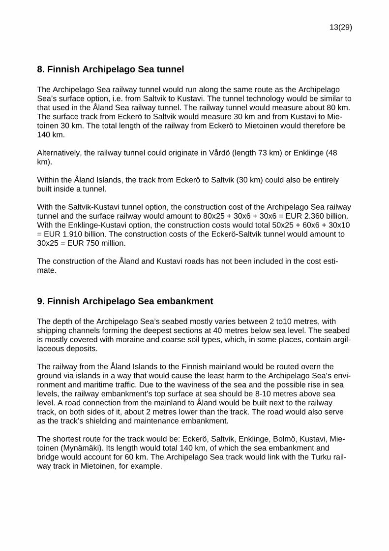
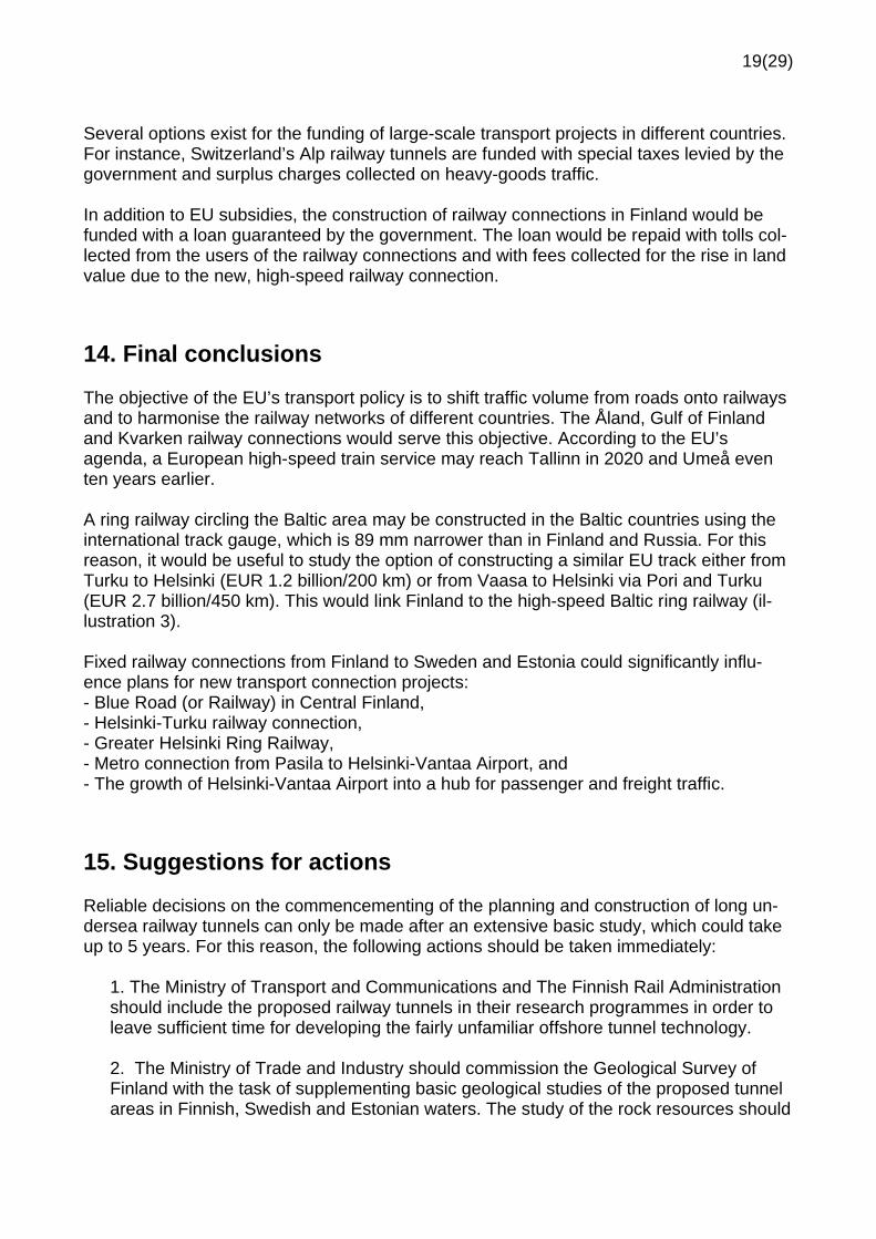
8. Finnish Archipelago Sea tunnel
The Archipelago Sea railway tunnel would run along the same route as the ArchipelagoSea’s surface option, i.e. from Saltvik to Kustavi. The tunnel technology would be similar tothat used in the Åland Sea railway tunnel. The railway tunnel would measure about 80 km.The surface track from Eckerö to Saltvik would measure 30 km and from Kustavi to Mietoinen 30 km. The total length of the railway from Eckerö to Mietoinen would therefore be140 km.
Alternatively, the railway tunnel could originate in Vårdö (length 73 km) or Enklinge (48km).
Within the Åland Islands, the track from Eckerö to Saltvik (30 km) could also be entirelybuilt inside a tunnel.
With the SaltvikKustavi tunnel option, the construction cost of the Archipelago Sea railwaytunnel and the surface railway would amount to 80x25 + 30x6 + 30x6 = EUR 2.360 billion.With the EnklingeKustavi option, the construction costs would total 50x25 + 60x6 + 30x10= EUR 1.910 billion. The construction costs of the EckeröSaltvik tunnel would amount to30x25 = EUR 750 million.
The construction of the Åland and Kustavi roads has not been included in the cost estimate.
9. Finnish Archipelago Sea embankment
The depth of the Archipelago Sea’s seabed mostly varies between 2 to10 metres, withshipping channels forming the deepest sections at 40 metres below sea level. The seabedis mostly covered with moraine and coarse soil types, which, in some places, contain argillaceous deposits.
The railway from the Åland Islands to the Finnish mainland would be routed overn theground via islands in a way that would cause the least harm to the Archipelago Sea’s environment and maritime traffic. Due to the waviness of the sea and the possible rise in sealevels, the railway embankment’s top surface at sea should be 810 metres above sealevel. A road connection from the mainland to Åland would be built next to the railwaytrack, on both sides of it, about 2 metres lower than the track. The road would also serveas the track’s shielding and maintenance embankment.
The shortest route for the track would be: Eckerö, Saltvik, Enklinge, Bolmö, Kustavi, Mietoinen (Mynämäki). Its length would total 140 km, of which the sea embankment andbridge would account for 60 km. The Archipelago Sea track would link with the Turku railway track in Mietoinen, for example.

14(29)
An alternative route for the track would be: Eckerö, Mariehamn, Lemland, Sommarö,Kökar, Korppoo, Nauvo, Parainen. The link with the Helsinki railway track would be madebetween Kaarina and Salo. This option will not be discussed in more detail.
Bridges would be used to cross the current shipping channels. The most important ofthese, the Kihti shipping channel (depth 10 m), is located between Vuosnainen and Jurmo.A bridge similar to the Raippaluoto bridge (length 1,045 m) would be of a suitable type forthe location if its dimensions (cable stayed bridge, clear span 26 m and span 250 m) awere sufficient. A bridge similar to the one in Puumalansalmi (composite girder bridge) couldbe built as an alternative solution.
The construction costs of the Kihti railway and road bridge (length 2 km, clear span 25 m)would amount to 2x2x24 = EUR 96 million.
If the Kihti bridge needs to have a clear span similar to that of the Öresund bridge (57 m),the railway bridge would then measure 8 km and the road bridge 4 km. The bridge’s construction costs in this case would amount to 8x24 + 4x24 = EUR 288 million.
An alternative plan would be to build a ship lock under the bridge for large vessels. In thiscase, large vessels could pass under the bridge through the lock, and the height of thebridge would not have to be increased. The lock would be built in the channel before thebridge in a location where the rock surface is at a depth of 010 m. A dam wall extendingto the rock surface would be built around the lock. The lock (capacity approximately 1 million cubic metres) would be excavated into the rock in dry conditions, protected by the damwall. The lock gates would extend to the surface of the rock, and down to the requireddepth of the channel. The lock’s dimensions: length 700, width 3040 metres and depth 50m. In order to enable the lock to be emptied quickly, two reservoirs (2 x 400,000 cubic metres) could be excavated into the rock. The construction costs of the ship lock would totalEUR 2550 million.
The cost of bridging other channels 5 metres deep (clear span under 25 m, bridge length 1km) would amount to about 2x24 = EUR 48 million.
The costs of small bridges over shipping channels are included in the unit costs of the surface track and surface road (EUR 10 million/km).
The average crosssectional area of the railway and road embankment in the sea sectionswould be about 500 square metres. Approximately 2025 million cubic metres of blastedrock would be needed for the sea embankment. This could be obtained from the ÅlandSea tunnel, for example, if this was being excavated at the same time.
The construction costs of the surface connection (Eckerö, Saltvik, Enklinge, Bolmö, Kustavi, Mietoinen), including the ship lock in the Kihti channel, would amount to 76x10 + 96 +48 + 50 + 60x6 = EUR 1.314 billion. This would allow large vessels to pass through theKihti channel. The Åland Islands and Kustavi road connections have not been included inthe cost estimate.

15(29)
According to the table (illustration 5), the options for the Åland Islands are:
Option 1 (“”tunnel+tunnel”). The total length of the Åland Sea and Archipelago Sea railway tunnels is 80+80=160 km. There would be 20 km of surface track on the Swedishside, 30 km in the Åland Islands and 30 km in Finland. The estimated construction costwould be EUR 4.5 billion. The roads across the Åland Sea, Archipelago Sea and the ÅlandIslands have not been included in the costs.
Option 2 (“”tunnel+embankment”). The construction costs of the Åland Sea railway tunneland the Archipelago Sea surface railway and road would total EUR 3.4 billion. The roadacross the Åland Sea has not been included in the cost. A ferry connection would transportroad traffic to Grisslehamn and Kapellskär.
Option 3 (“”bridge+embankment”). The construction costs of the Åland Sea surface railway (large sea bridge) would exceed EUR 5.0 billion. The construction costs of the Archipelago Sea embankment railway and road would be EUR 1.3 billion. The constructioncosts of the surface connection would exceed EUR 6.3 billion. The transport connectionincludes a fixed railway and road connection between Finland and Sweden.
Option 4 (“”single continuous tunnel”). A rock tunnel could also be constructed across theÅland Islands, between the Åland Sea and the Archipelago Sea. The tunnel’s total lengthwould be 190 km. In addition, 50 km of surface railway track would be required. The construction costs would total EUR 5.0 billion.
Option 5 (“”the lowcost option”). This would not be a completely fixed connection, since itincludes ferry crossings. A railway tunnel would be built from Kustavi to Enklinge, and anembankment via Saltvik to Eckerö. Blasted rock from the tunnel excavation work wouldprovide material for the embankment for the Archipelago Sea surface connection. A trainconnection would continue by ferry from Eckerö to Grisslehamn (2 hours) and onwards toGimo. An embankment would be constructed for road traffic using the current island roadsfrom Kustavi to the Åland Islands (Eckerö) via Bolmö, Brandö, Enklinge and Vårdö. TheKihti channel would be crossed using a car ferry. Car ferries would be used to transportroad traffic from Åland to Kapellskär (E18). The construction cost of this option would totalabout EUR 2.3 billion.
10. Gulf of Finland tunnel
Two of the main route options for the Gulf of Finland railway tunnel include: a connectionfrom the port of Muuga in Estonia to Porkkala or to Pasila in Finland. The two options forthe Gulf of Finland railway tunnel are presented in the 2003 edition of the Finnish MaritimeAdministration’s nautical maps of the western part of the Gulf of Finland ion a scale of1:250,000, as well as in two longitudinal profiles.
With both options the track would link with the Muuga coastal railway on the Narva mainroad in Mardu, Estonia. On the Finnish side, the Porkkala track option would link with thecoastal railway in Jorvas in the municipality of Kirkkonummi. The Pasila track option wouldlink with the main railway line after the Pasila depot.

16(29)
The tunnel option through Naissaar has been discussed in an article at the World TunnelCongress in Oslo (Anttikoski and Vilo 1999). A new estimate of this option has not yetbeen made.
The seabed has a maximum depth of 90 to 100 metres. The Precambrian hard bedrock onthe Finnish side descends gently at an incline of about 0.2% southwards, and drillingsconducted in Tallinn have found its surface at a depth of 100 to 150 metres below sealevel. In Estonia, the granite bedrock is covered by a layer of softer sandstone, claystoneand limestone. Geological surveys for the Gulf of Finland tunnel have not yet been started.
The tunnel’s longitudinal incline could be a maximum of 1.2 to 2.0%. The tunnel’s lowestsection would be at a depth of 220 metres below sea level, which would leave a layer ofhard rock above the tunnel estimated to be at least 40 metres thick. The tunnel’s longitudinal profile has been placed with the assumption that the maximum depth of the bedrocksurface in the sea region is 150 metres below sea level.
Undersea tunnels would primarily be constructed by drilling and blasting the hard bedrockall the way to the Estonian mainland. On the Estonian side, the tunnel would be constructed using full profile drilling, with reinforced concrete arches providing support.
A location for the railway track and a terminal in Äigrumäe on the Viims peninsula hasbeen marked on the general plan of the Province of Harju, in Estonia.
The general plan for the Porkkala peninsula would allow for the railway track to link withthe coastal railway, even though this has not been marked ion the plan. The preliminarylocation for the mouth of the tunnel has been placed in the vicinity of Piispankylä andLångvik on the Porkkala peninsula. There are no plans for a possible entrance to the tunnel in the Pasila area. The preliminary location for the tunnel’s mouth has been placed inthe depot area, next to Veturitie Road.
At sea, entrances to the work tunnel and work bases would be built on islands along theroute. These islands are: Aegna, Naissaar, Katajaluoto and Järvö. In addition, manmadeislands with service shafts to the tunnels would be created on sea banks (water depth lessthan 10 m). Sea banks along the route include Uusmadal, Tallinna madal, Gråskärsbådan,Ulkomatala and Lybeckshällarna. “Railway lighthouse buildings” would be constructed onthe manmade islands, and these would house maintenance facilities, a service shaft anda ventilation exhaust chimney. Wind power stations could also be built on the manmadeislands for the generation of energy.
The length of the tunnel for these two options would be 7085 km. In addition, about 10 kmof surface track would have to be built in order to link with existing railway lines in Estoniaand Finland. The total length of the track would be 8095 km.
The construction costs of the Porkkala option would amount to 58x25 + 12x65 +10x6 =EUR 2.290 billion, while the Pasila option would cost 73x25 + 12x65 + 10x6 = EUR 2.665billion.
The project would also serve as a significant source of building stone material, since thereis permanent demand for hard building stone (granite) in Estonia and the rest of the Balticcountries. The excavation of the railway tunnel would produce about 17 million cubic me

17(29)
tres of blasted rock. About 3 million cubic metres of this would be used to create the manmade islands, but the rest could be crushed in the tunnels for building material and transported to Estonia by sea, for example, via the Kantvik freight port. If the value of theblasted rock at the port could be EUR 5/cubic metre, then its total value would amount toEUR 70 million, or about 3% of the construction costs.
11. Kvarken tunnel
The route of the Kvarken tunnel has been indicated on the Norden map (1:2,000,000). Thelength of the track from the new Botniabana (Bothnia Line) in Holmsund to Vaasa wouldbe about 100 km. The tunnel from Holmsund to Raippaluoto would measure 60 km, andthe tunnel between Raippaluoto and Vaasa 20 km. In addition, different options would include between 20 and 40 km of surface railway tracks.
The tunnel would be easier to construct than the connections across the Åland Sea, theArchipelago Sea and the Gulf of Finland, because the seabed is mostly only 10 to 30 metres deep. Construction costs have been estimated using the same railway tunnel unitprices as in the other two projects evaluated.
The construction costs of the different options vary between EUR 1.7 and 2.1 billion.
12. Summary of construction costs
The table below (illustration 5) shows a comparison of construction costs. The cost estimates of fixed transport connections vary between EUR 1.7 and 8.0 billion for the connection between Finland’s and Sweden’s coastal railroads, and EUR 2.3 and 2.7 billion for theconnection between Finland’s and Estonia’s coastal railroads.
The smallest environmental effects would be caused by continuous rock tunnels, whichwould measure 190 km in the Åland Islands, 70 km in the Gulf of Finland and 80 km inKvarken. The construction costs would amount to EUR 5.0 billion, EUR 2.3 billion andEUR 2.1 billion respectively.
The costs of transport connections can be compared, for example, to the Öresund or theGreat Belt transport connection (EUR 4.0 to 5.0 billion at 2000 price levels) or the plannedtransport connection across the Fehmarn strait between Denmark and Germany (EUR 5.0billion).

18(29)
Illustration 5. The costs in this summary table are quoted at 2007 price levels. Value addedtax and the costs of owner have not been included. The main unit costs used in this summary table are: Hard rock tunnel (23 tunnels) 25 EUR million/km Soft rock tunnel (e.g. on the Estonian mainland) 65 ” Embankment railway (2 tracks, including bridges) 6 ” Embankment road next to embankment railway(2 lanes, including bridges) 4 ”
13. Comments concerning financing
Units costs are based on 2007 price levels. Provisions should be made for an increase inconstruction costs due to the fact that construction cannot be started infor 5 years at theearliest.
No geological surveys have been conducted for the undersea tunnels. The geology of theArchipelago Sea and Kvarken is well suited for the construction of tunnels. On the otherhand, the bedrock under the Åland Sea and the Gulf of Finland is of a lower quality, andunexpected changes in these areas may increase construction costs and prolong the duration of the project.
The EU has previously supported the construction of transport corridors listed on itsagenda with a 1020% share of the costs. Moreover, it has funded up to 75% of the costsof preliminary studies.
Fixed transport connections across the Baltic SeaConnection tunnel surface altitude constr. cost
km km maximum +/ EUR millionÅLAND ISLANDSÅland Sea Tunnel 80 20 180 2 100 Embankment (large sea bridge) 90 70 over 5 000 Railway and car ferry (ferry 45 km) 30 300Archipelago Sea (and Åland Islands) Tunnel 80 60 160 2 400 Embankment (large sea bridge) 140 30 1 300 Tunnel under Åland as well 110 30 160 2 900
GULF OF FINLANDPorkkala 70 12 220 2 300Pasila 85 7 220 2 700
KVARKEN Tunnel and embankment 60 40 130 1 700 2 tunnels and embankment 60+20=80 20 130 2 100
19(29)
Several options exist for the funding of largescale transport projects in different countries.For instance, Switzerland’s Alp railway tunnels are funded with special taxes levied by thegovernment and surplus charges collected on heavygoods traffic.
In addition to EU subsidies, the construction of railway connections in Finland would befunded with a loan guaranteed by the government. The loan would be repaid with tolls collected from the users of the railway connections and with fees collected for the rise in landvalue due to the new, highspeed railway connection.
14. Final conclusions
The objective of the EU’s transport policy is to shift traffic volume from roads onto railwaysand to harmonise the railway networks of different countries. The Åland, Gulf of Finlandand Kvarken railway connections would serve this objective. According to the EU’sagenda, a European highspeed train service may reach Tallinn in 2020 and Umeå eventen years earlier.
A ring railway circling the Baltic area may be constructed in the Baltic countries using theinternational track gauge, which is 89 mm narrower than in Finland and Russia. For thisreason, it would be useful to study the option of constructing a similar EU track either fromTurku to Helsinki (EUR 1.2 billion/200 km) or from Vaasa to Helsinki via Pori and Turku(EUR 2.7 billion/450 km). This would link Finland to the highspeed Baltic ring railway (illustration 3).
Fixed railway connections from Finland to Sweden and Estonia could significantly influence plans for new transport connection projects: Blue Road (or Railway) in Central Finland, HelsinkiTurku railway connection, Greater Helsinki Ring Railway, Metro connection from Pasila to HelsinkiVantaa Airport, and The growth of HelsinkiVantaa Airport into a hub for passenger and freight traffic.
15. Suggestions for actions
Reliable decisions on the commencementing of the planning and construction of long undersea railway tunnels can only be made after an extensive basic study, which could takeup to 5 years. For this reason, the following actions should be taken immediately:
1. The Ministry of Transport and Communications and The Finnish Rail Administrationshould include the proposed railway tunnels in their research programmes in order toleave sufficient time for developing the fairly unfamiliar offshore tunnel technology.
2. The Ministry of Trade and Industry should commission the Geological Survey ofFinland with the task of supplementing basic geological studies of the proposed tunnelareas in Finnish, Swedish and Estonian waters. The study of the rock resources should

20(29)
be conducted in cooperation with the corresponding institutes in Finland’s neighbouring countries.
3. VTT Technical Research Centre of Finland should assemble a working group composed of experts working in its construction laboratories and in universities in order tostudy the particular details of undersea railway tunnels. It is necessary to develop theHEPAC technology and security of the railway tunnels in particular. The tunnels’ airconditioning and smoke abatement systems and the removal of water leaks will posethe biggest challenges.
Espoo, February 2008
Usko Anttikoski
M. Sc. (Eng.), geotechnics expert, [email protected]
16. Appendices:
Norden map 1:2,000,000 on the cover page of this memo’s text section Corresponding longitudinal profiles (4 pages) Sketches of structure crosssections (5 pages)
Nautical charts of the Finnish Archipelago Sea and the western part of the Gulf ofFinland 1:250,000 (6 pages) separate appendices

21(29)
Appendices:
Profiles (4 pages)
The Åland Sea

22(29)
The Åland Isles
23(29)
The Archipelago Sea
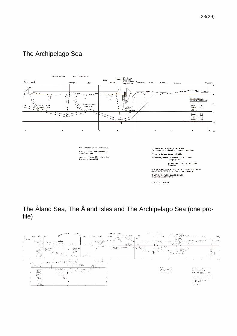
The Åland Sea, The Åland Isles and The Archipelago Sea (one profile)

24(29)
The Gulf of Finland

25(29)
Construction principles (5 pages)

26(29)

27(29)

28(29)

29(29)