Embed Size (px)
Citation preview

USUSAT CDR / ION-F IDR DOCUMENT:
ATTITUDE DETERMINATION SYSTEM
CAMERA ALGORITHM SOFTWARE DOCUMENT
Document AuthorsPrapat Sripruetkiat [email protected]
Utah State UniversityMechanical and Aerospace Engineering
Logan, Utah 84322
Last Updated: 7/2/01 8:00 PMDocument Number: AA-22707-DOC03-1.doc Revision Number: 1

2
REVISION HISTORY
Revision Description Author Date Approval
1 Initial Release Prapat
Sripruetkiat
7/2/01 Pending

3
ContentIntroduction 6Software Requirements 6Conceptual Design 6Part 1: Sun Algorithm 7 main program 7- init_sun.m 7- sun_main.m 8-- sun_algorithm.m 9--- checksun.m 10---- scatter.m 11--- swsize.m 12--- rowscan.m 12--- lp.m 13--- normal.m 13--- stepindex.m 13--- change.m 14--- antidis_inter.m 14---- normalize.m 15---- comp_distortion_oulu.m 15--- center.m 16--- sunvec.m 17--- cc2sc.m 17Part 2: Horizon Algorithm 18 main program 18- init_horizon.m 18- horizon_main.m 18-- horizon_algorithm.m 19--- findedge.m 20--- lp.m, normal.m, stepindex.m 23-- check_horizon.m 23-- antidis_inter.m 24--- normalize.m, comp_distortion_oulo.m 24-- center.m 24-- check_shadow.m 24-- camco.m 24Part 3: Captures Image 26- Gaussian filter 26

4
Part 4:Accessories Code 27- Angle between two vectors 27- sub-pixel method 27- cutoff.m 29- 1-D Gaussian filer and edge detection from ideal edge 30Analysis the source code and some experiment 32

5
Figure & table contentFigure 1 Block diagram of main sun vector program 7Figure 2 Block diagram of sun algorithm 9Figure 3 Block diagram of main sun vector program 18Figure 4 Block diagram of horizon algorithm 19Figure 5 Ideal edge detection by 1-D Gaussian filter, gradient
based and Laplacian of Gaussian edge detection 31Figure 6 Experiment of sun images for analysis sun algorithm 33
Table 1 Analysis program performance of sun algorithm of image b17.bmp 32
Table 2 Analysis program performance of horizon algorithm of image bright_pic.bmp 32
Table 3 Analysis program performance of sun algorithm 20 images 34

6
Camera Algorithm Softwarefor Attitude Determination
Introduction: This document outlines the source code of camera algorithm based on MATLAB.
Source codes are divided four parts: sun algorithm, horizon algorithm, and captures image and accessories code. Sun and horizon algorithm will be changed to C code and used in satellite computer. Captures image and accessories codes are using to analysis the data by general PC on the ground.
Software Requirements:A. Sun and horizon algorithm need to change to C code and use in computer of
satelliteB. Capture image and accessories codes required MATLAB 5.X program.
Conceptual Design:The main concept design covers from highest requirement to lowest requirement.
1. Fast processing. Current design sun and horizon vector will update every 5second. Computer, which be using to analysis, with CPU Pentium 200 MHz1 runs fastest than computer on satellite with CPU 80 MHz about 5 to 10 time. Now, the estimated time of sun algorithm about 0.22-0.44 sec for one sun image on MATLAB. The estimated time of horizon algorithm about 1.05-1.22 sec for one horizon image on MATLAB.
2. Detectable most situations. Camera algorithm will cover all situations for visual wavelength, such as ecliptic, sun and earth appearing in same image, and eliminate the noise from star, noon and another spacecraft.
3. Accuracy. The design value will be 3 degree.
1 Computer runs with CPU speed 200 MHz and 76 Mb memory.

7
Part 1: Sun Algorithm
Main program
Figure 1. Block diagram of main sun vector program
init_sun.m Objective: Initialize constant value and storage in memory for sun sensor.Global Constant:R_cc2sc Rotation matrix of camera coordinate respect to satellite body fixed coordinate.
Size [3x3] im Image from Fuga camera. Size [512x512] 8-bitfc Focus length in pixel units of x and y camera axis. Size [2x1x4]cc Principal axis in pixel units of u and v position. Size [2x1x4]kc Distortion constants for non linear equation. Size [5x1x4]uL Lower u value of sub-window. Size [1] constantuH Higher u value of sub-window. Size [1] constantvL Lower v value of sub-window. Size [1] constantvH Higher v value of sub-windows. Size [1] constant rowS Position and number of row scanning line. Current design scans at row 2, 4, 6, 8
10, 12, 14, 16, 18 and 20. Size [1x10]Local Constant:Rdata Rotation matrix of camera coordinate respect to satellite body fixed coordinate.
Size [3x3x4] fcdata Focus length in pixel units of x and y camera axis. Size [2x1x4]ccdata Principal axis in pixel units of u and v position. Size [2x1x4]kcdata Distortion constants for non linear equation. Size [5x1x4]imdata Image from Fuga camera. Size [512x512x4] 8-bit. ***On flight version, each
image will install in SimRAM one image per execution. We don’t need all 4 images in memory***.
Source code:
% init_sun.m Initialize the constant for sun algorithm global im R_cc2sc fc cc kc uL uH vL vH rows% --------------------------------------------------%Under this line, constants will be updateable to optimize CPU time and accuracy of space image. uL=-5 ; uH=25; vL=-9; vH=10; rowS=[2:2:20];
Sun algorithm(sun_algorithm.m)
Initial sun(init_sun.m)
Sun vector(sv_sc)
Solar Switchsolar=’1’ or ’0’
Storage image by image in SimRam i=1:4

8
% --------------------------------------------------% R_cc2sc constant
% cam#1 [Psi,Phi,Psi]=[90,140,0]; R_cc2sc1% cam#2 [Psi,Phi,Psi]=[-90,140,0]; R_cc2sc2% cam#3 [Psi,Phi,Psi]=[180,90,0]; R_cc2sc3R_cc2sc1=[0.76604 0 0.64279; 0 1 0; 0.64279 0 0.76604];R_cc2sc2=[-0.76604 0 0.64279; 0 –1 0; -0.64279 0 0.76604];R_cc2sc3=[0 0 1; 0 -1 0;-1 0 0];R_cc2sc4=[0 0 1; 0.86603 -0.5 0; -0.5 -0.86603 0];Rdata(:,:,1)=R_cc2sc1; Rdata(:,:,2)=R_cc2sc2; Rdata(:,:,3)=R_cc2sc3;Rdata(:,:,4)=R_cc2sc4;
% --------------------------------------------------% im constant
im1=imread('b01.bmp');im2=imread('dark_fuga.bmp')im3=im2;im4=im2;imdata(:,:,1)=im1; imdata(:,:,2)= im2; imdata(:,:,3)=im3; imdata(:,:,4)= im4;
% --------------------------------------------------% fc cc kc constant
fc1=[383.17911 384.08776]' ; cc1=[ 259.73519 304.21791]';kc1=[-0.36142 0.11366 -0.00173 0.00148 0.00000]'; fcdata(:,:,1)=fc1; fcdata(:,:,2)=fc1; fcdata(:,:,3)=fc1; fcdata(:,:,4)=fc1; ccdata(:,:,1)=cc1; ccdata(:,:,2)=cc1; ccdata(:,:,3)=cc1; ccdata(:,:,4)=cc1;kcdata(:,:,1)=kc1; kcdata(:,:,2)=kc1; kcdata(:,:,3)=kc1; kcdata(:,:,4)=kc1;
sun_main.m Objective: The main program of sun vector determination and storage each image
and parameter in memory a time for execution. Program periodic executes when solar switch is on (‘1’)
Constant: same as init_main.mSource code:
switch solarcase '1' %Have sun and run sun algorithm
for CamNo=1:4 im=imdata(:,:,CamNo); R_cc2sc=Rdata(:,:,CamNo); fc=fcdata(:,:,CamNo); cc=ccdata(:,:,CamNo); kc=kcdata(:,:,CamNo); sv_sc(:,:,CamNo)=sun_V1(im); end; case '0' % No sun and Don't run sun algorithm end;

9
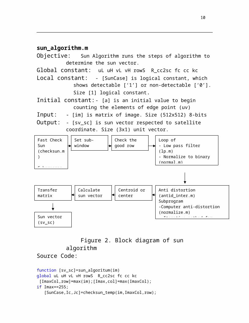
sun_algorithm.m Objective: Sun Algorithm runs the steps of algorithm to determine the sun vector. Global constant: uL uH vL vH rowS R_cc2sc fc cc kcLocal constant: - [SunCase] is logical constant, which shows detectable [‘1’] or non-
detectable [‘0’]. Size [1] logical constant.Initial constant: - [a] is an initial value to begin counting the elements of edge point
(uv)Input: - [im] is matrix of image. Size (512x512) 8-bitsOutput: - [sv_sc] is sun vector respected to satellite coordinate. Size (3x1) unit
vector.
Figure 2. Block diagram of sun algorithmSource Code:
function [sv_sc]=sun_algoritum(im)global uL uH vL vH rowS R_cc2sc fc cc kc [ImaxCol,row]=max(im);[Imax,col]=max(ImaxCol);if Imax==255; [SunCase,Ic,Jc]=checksun_temp(im,ImaxCol,row);else SunCase='0'; end;
switch SunCase % Using case condition case('0') sv_sc=[0; 0; 0]; break; % no sun in image case('1') a=0 ; % initialize in sub-window(CHANGE.M)
[subw,ulow,vlow]=swsizeV1(im,Ic,Jc); %sub-window 20x31 pixels
[CorrectRow]=rowscan(subw,8); % check good row for scanning
for i=1:length(CorrectRow); % use scanning row follow Correct Row rowN(i,:)=lp(subw(CorrectRow(i),:)); nr(i,:)=normal(rowN(i,:),250); % normalize signal to be binary
if max(nr(i,:))==0 | min(nr(i,:))==1;
Fast Check Sun (checksun.m)
Subprogram- Check scatter (scatter.m)
Set sub-window (swsize.m)
Check the good row (rowscan.m)
Loop of - Low pass filter (lp.m) - Normalize to binary (normal.m)- Count the signal (stepindex.m)- Change coordinate (change.m)
Anti distortion (antid_inter.m)Subprogram-Computer anti-distortion (normalize.m)- Iterative method for compensation (comp_distortion_oulu.m)
Centroid or center (center.m)
Calculate sun vector (sunvec.m)
Transfer matrix (cc2sc.m)
Sun vector(sv_sc)
10
% no data and repeat another line. else edgenum=stepindex(nr(i,:)); % count the signal % change sub-window coordinate to original coordinate for point=1:length(edgenum);a=a+1;
UV(a,:)=changeV1(edgenum(point),CorrectRow(i),ulow,vlow); end; end;
end;
[Xp, Yp]= antid_inter(UV); % anti-distortioncent=center([Xp,Yp]); % calculate center pointsv_cc = sunvecV1(cent); % sun vector reference to camera sv_sc = cc2sc(sv_cc); % change sun vector from camera
% coordinate to satellite coordinateend;
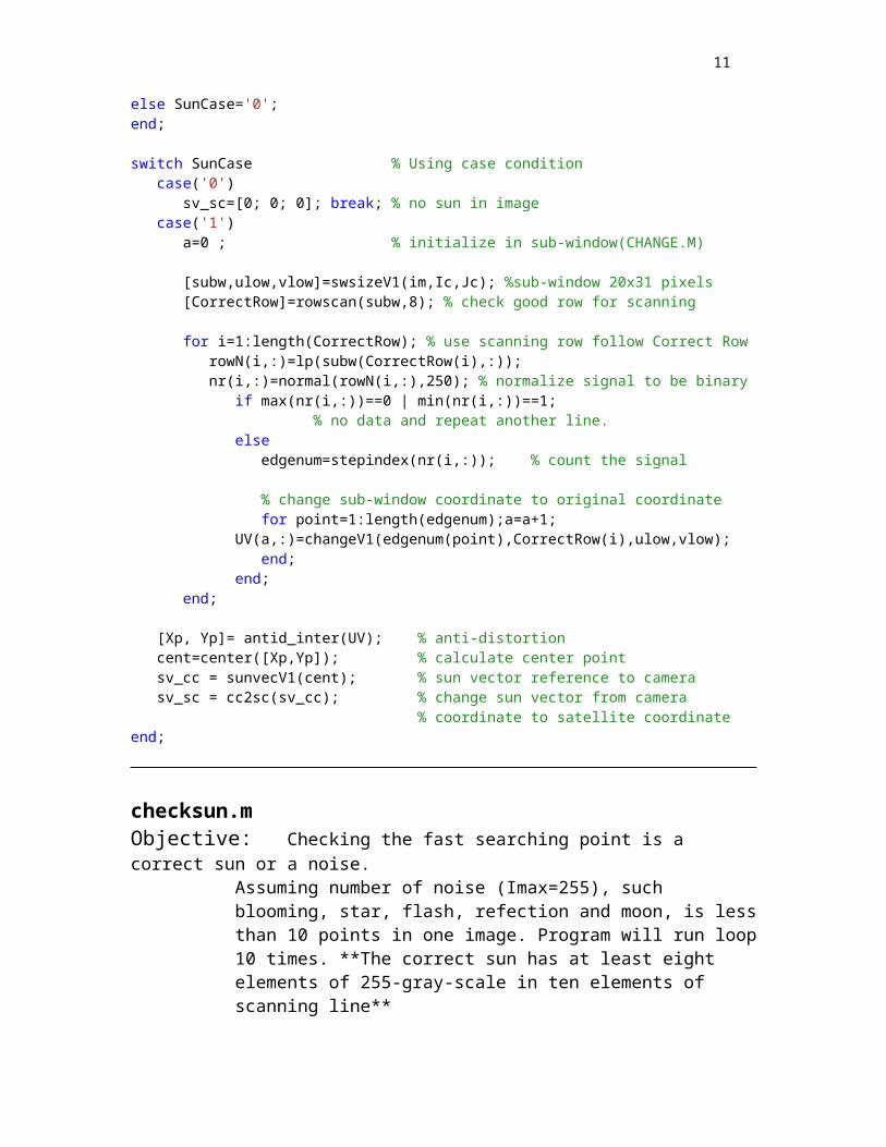
checksun.m Objective: Checking the fast searching point is a correct sun or a noise.
Assuming number of noise (Imax=255), such blooming, star, flash, refection and moon, is less than 10 points in one image. Program will run loop 10 times. **The correct sun has at least eight elements of 255-gray-scale in ten elements of scanning line**
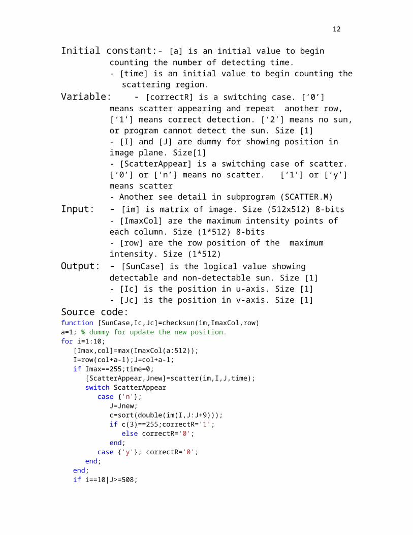
Initial constant:- [a] is an initial value to begin counting the number of detecting time.- [time] is an initial value to begin counting the scattering region.
Variable: - [correctR] is a switching case. [‘0’] means scatter appearing and repeat another row, [‘1’] means correct detection. [‘2’] means no sun, or program cannot detect the sun. Size [1]- [I] and [J] are dummy for showing position in image plane. Size[1]- [ScatterAppear] is a switching case of scatter. [‘0’] or [‘n’] means no scatter. [‘1’] or [‘y’] means scatter- Another see detail in subprogram (SCATTER.M)
Input: - [im] is matrix of image. Size (512x512) 8-bits- [ImaxCol] are the maximum intensity points of each column. Size (1*512) 8-bits - [row] are the row position of the maximum intensity. Size (1*512)
Output: - [SunCase] is the logical value showing detectable and non-detectable sun. Size [1]- [Ic] is the position in u-axis. Size [1] - [Jc] is the position in v-axis. Size [1]
Source code:function [SunCase,Ic,Jc]=checksun(im,ImaxCol,row)a=1; % dummy for update the new position.for i=1:10; [Imax,col]=max(ImaxCol(a:512)); I=row(col+a-1);J=col+a-1; if Imax==255;time=0; [ScatterAppear,Jnew]=scatter(im,I,J,time); switch ScatterAppear
11
case {'n'}; J=Jnew;
c=sort(double(im(I,J:J+9))); if c(3)==255;correctR='1'; else correctR='0'; end; case {'y'}; correctR='0'; end; end; if i==10|J>=508;
correctR='2'; end; switch correctR case '2';
SunCase='0';Ic=0;Jc=0; break; case '1';
SunCase='1';Ic=I;Jc=J; break; case '0';
a=J+1; %continue end;end;
scatter.mObjective: Checking the scatter points have 255-gray-scale intensity. This program is
the subprogram of CHECKSUN.M. When data have scatters, program will find the next 255-gray-scale position in the same row.
Fact: From experiment, characteristics of scatter (Imax=255) appear continuous one or two points and have neighborhoods intensity less than 250-gray-scale. **The correct sun has at least eight elements of 255-gray-scale in ten elements of scanning line**
Variable - [J2] is the value of J+2. Size[1]- [b] is the sort data from J to J2. Size[1] - [Jlo] is the lower J in u-axis. 508 is maximum. Size [1] - [Jhi] is the lower J in u-axis. 512 is maximum. Size [1] - [InewCol] is the new maximum intensity. Size [1]- [new] is dummy of Jnew for repeating program. Size [1]
Initial constant:- [a] is an initial value to begin counting the detecting time.Input: - [im] is matrix of image. Size (512x512) 8-bits
- [I] is the position in u-axis, which may be boundary of sun. Size [1]- [J] is the position in v-axis, which may be boundary of sun. Size [1]- [time] is counting number the scattering region. Size [1]
Output: - [ScatterAppear] is logical value, which shows scatters appearing [‘1’] or [‘y’] and scatters non-appearing [‘0’] or [‘n’]. Size [1]
- [Jnew] is the position in v-axis and update the J constant. Size [1]
Source code:
function [ScatterAppear,Jnew]=scatter(im,I,J,time)time=time+1; % assuming scattering regions have less than 4 regions
12
if time==4; ScatterAppear='y'; Jnew=J;
break; end;
J2=J+2;b=sort(double(im(I,J:J2)));if b(1)>=250;
ScatterAppear='n';Jnew=J; else
Jlo=min(508,J2); % using 508 for lower limitedJhi=min(J+23,512); % the upper limit of camera
[InewCol,new]=max(im(I,Jlo:Jhi)); if InewCol==255;
[ScatterAppear,Jnew]=scatter(im,I,(new+Jlo-1),time); elseif InewCol<255;
Jnew=J;ScatterAppear='y'; %Data have scatter end;end;
swsize.mObjective: create sub-window to cover sunGlobal constant:- uL uH vL vH ( see details in INIT_SUN.M)Input: - [im] is matrix of image. Size (512x512) 8-bits
- [us] and [vs] are located point of sun from sun searching. Size [1] Output: -[sws] is a sub-window matrix. Size variable by uL uH vL vH and
position. The initial value sets up at 20x31 pixels. -[ulow] and [vlow] are the original point of sub-window. Size [1]
Source code:function [sws,ulow,vlow]=swsize(image,us,vs);global uL uH vL vHulow=(us+uL);uhigh=(us+uH);vlow=(vs-vL); vhigh=(vs+vH); ulow=min(ulow,493);ulow=max(ulow,1);uhigh=min(uhigh,512);vlow=min(vlow,490);vlow=max(vlow,1);vhigh=min(vhigh,512);sws=im(ulow:uhigh,vlow:vhigh);
rowscan.mObjective: finds the acceptable rows, which have more than COUNT elements of the highest intensity. This program setups COUNT at 8 elements at SUN_ALGORITUM.M. Global constant:- [rows] ( see details in INIT_SUN.M)Input: - [subw] is matrix of image. Size (20x31) 8-bits
- [count] is the design number of acceptable . Size [1] Output: -[ rowAccept]

13
function [rowAccept]=rowscan(subw,count)global rowSleng=length(subw); c=0;AcceptNo=leng+1-count;rowAccept=0;for i=1:length(rowS); b=sort(double(subw(rowS(i),:))); if b(AcceptNo)==255;c=c+1;rowAccept(c)=rowS(i); end;end;
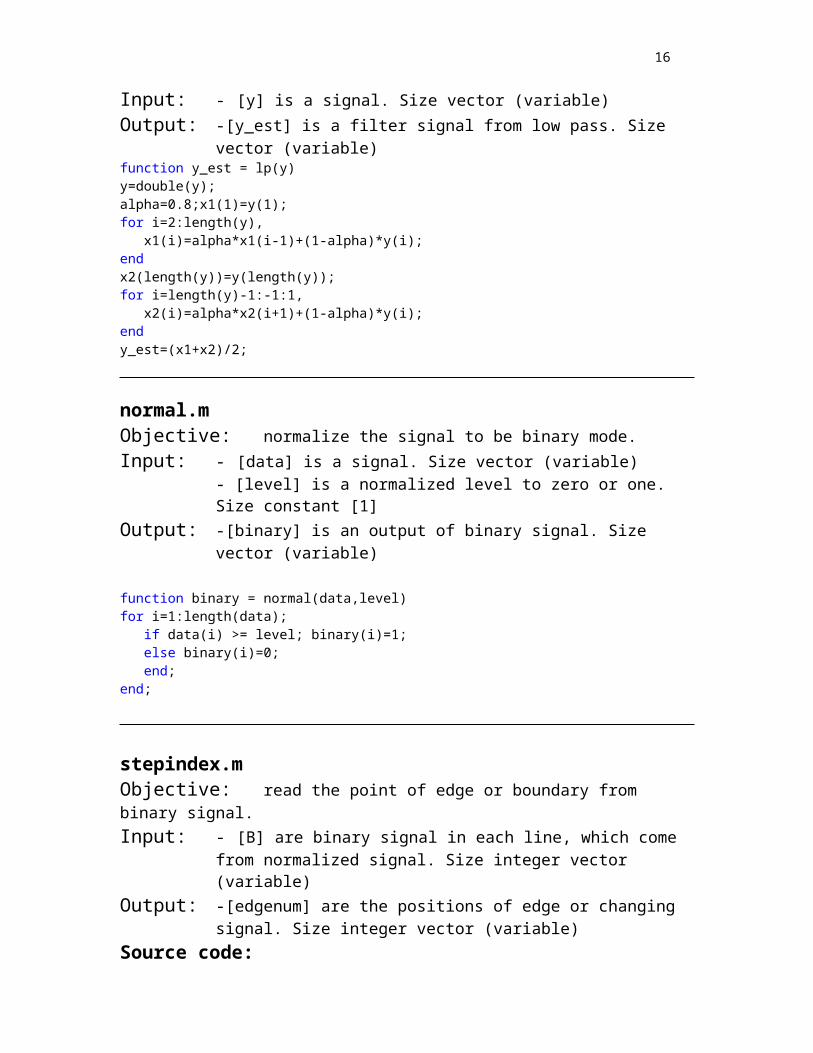
lp.mObjective: Low pass filter reduce the noise in signal.Local constant:- [alpha] the low pass filter ratioInput: - [y] is a signal. Size vector (variable) Output: -[y_est] is a filter signal from low pass. Size vector (variable) function y_est = lp(y)y=double(y);alpha=0.8;x1(1)=y(1);for i=2:length(y),
x1(i)=alpha*x1(i-1)+(1-alpha)*y(i);endx2(length(y))=y(length(y));for i=length(y)-1:-1:1,
x2(i)=alpha*x2(i+1)+(1-alpha)*y(i);endy_est=(x1+x2)/2;
normal.mObjective: normalize the signal to be binary mode.Input: - [data] is a signal. Size vector (variable)
- [level] is a normalized level to zero or one. Size constant [1] Output: -[binary] is an output of binary signal. Size vector (variable)
function binary = normal(data,level)for i=1:length(data); if data(i) >= level; binary(i)=1; else binary(i)=0; end;end;
stepindex.mObjective: read the point of edge or boundary from binary signal.Input: - [B] are binary signal in each line, which come from normalized signal.
Size integer vector (variable) Output: -[edgenum] are the positions of edge or changing signal. Size integer
vector (variable)Source code:

14
function edgenum = stepindex(B)ro=size(B,1);co=size(B,2); for i=1:ro; % calculate each line c=1;for j=1:co-1; if B(i,j)~=B(i,j+1)& B(i,j)==0; edgenum(i,c)=j+1; c=c+1; elseif B(i,j)~=B(i,j+1) & B(i,j)==1; edgenum(i,c)=j; c=c+1; end;end;end;
change.mObjective: change the sub-window position (u,v) to be the image reference
frame(U,V)Input: -[edgenum] are the positions of edge or changing signal. Size integer
vector (variable)-[rowNo] is the positions of each rows. Size integer constant [1]-[ulow] is the original u-axis of sub-window. Size integer constant [1]-[vlow] is the original u-axis of sub-window. Size integer constant [1]
Output: -[UV] are the positions of edge or changing signal, which counted Size integer vector (variable)
Source Code:function UV=change(edgenum,rowNo,ulow,vlow)[ro,co]=size(edgenum);c=1;for i=1:ro; for j=1:co; uv_subw(c,:)=[rowNo edgenum(i,j)]; c=c+1; end;end;UV=[uv_subw(:,1)+ulow uv_subw(:,2)+vlow];
antidis_inter.mObjective: changes the distorted points to position for camera model.Global constant: fc cc kcInput: -[pixel_position] are distortion image or real image from camera.
Size vector (variable)Output: -[Xp,Yp] are points for camera model. Size vector (variable)Source Code:
function [Xp,Yp] = antid_inter(pixel_position)alpha_c = 0;global fc cc kc

15
x_kk=pixel_position'; [xn] = normalize(x_kk,fc,cc,kc,alpha_c);xd=xn';KK=[ fc(1) alpha_c * fc(1) cc(1); 0 fc(2) cc(2); 0 0 1 ]; a(1:length(xd(:,1)))=1; % make dummy of row vector =1XYp = KK*[xd(:,1) xd(:,2) a(:)]' ;Xp=XYp(1,:)'; Yp=XYp(2,:)';
normalize.mObjective: Computes the normalized coordinates xn given the pixel coordinates x_kk
and the intrinsic camera parameters fc, cc and kc.
Input: [x_kk] Feature locations on the images fc, cc, kc and alpha_c are as same as the INIT_SUN.MOutput: [xn] Normalized feature locations on the image plane (a 2XN matrix)Source Code:function [xn] = normalize(x_kk,fc,cc,kc,alpha_c),
% First: Subtract principal point, and divide by the focal length:x_distort = [(x_kk(1,:) - cc(1))/fc(1);(x_kk(2,:) - cc(2))/fc(2)];
% Second: undo skewx_distort(1,:) = x_distort(1,:) - alpha_c * x_distort(2,:);
if norm(kc) ~= 0,% Third: Compensate for lens distortion:xn = comp_distortion_oulu(x_distort,kc);
else xn = x_distort;end;
comp_distortion_oulu.mObjective: Compensates for radial and tangential distortion by Iterative method for
compensation. Model from Oulu university. Input: [xd] is a distorted (normalized) point coordinates in the image plane. Size
(2xN matrix)[k] is the distortion coefficients (radial and tangential). Size (4x1 vector)
Output: [x] undistorted (normalized) point coordinates in the image plane. Size (2xN matrix )
Source Code:
function [x] = comp_distortion_oulu(xd,k);
if length(k) == 1,
16
[x] = comp_distortion(xd,k);else k1 = k(1); k2 = k(2); k3 = k(5); p1 = k(3); p2 = k(4); x = xd; % initial guess for kk=1:5; r_2 = sum(x.^2); k_radial = 1 + k1 * r_2 + k2 * r_2.^2 + k3 * r_2.^3; delta_x = [2*p1*x(1,:).*x(2,:) + p2*(r_2 + 2*x(1,:).^2) ;
p1 * (r_2 + 2*x(2,:).^2)+2*p2*x(1,:).*x(2,:)]; x= (xd - delta_x)./(ones(2,1)*k_radial); end; end;
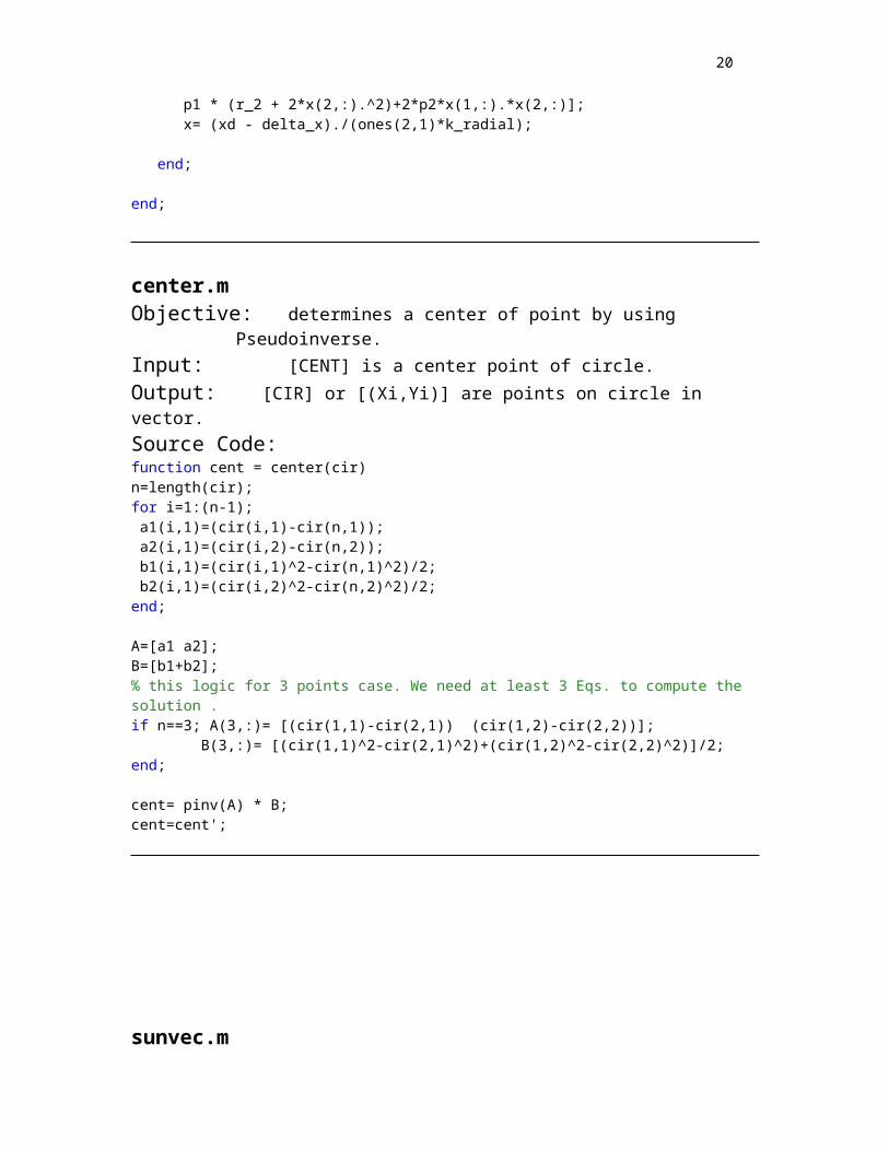
center.mObjective: determines a center of point by using Pseudoinverse. Input: [CENT] is a center point of circle.Output: [CIR] or [(Xi,Yi)] are points on circle in vector.Source Code:function cent = center(cir) n=length(cir);for i=1:(n-1); a1(i,1)=(cir(i,1)-cir(n,1)); a2(i,1)=(cir(i,2)-cir(n,2)); b1(i,1)=(cir(i,1)^2-cir(n,1)^2)/2; b2(i,1)=(cir(i,2)^2-cir(n,2)^2)/2;end;
A=[a1 a2];B=[b1+b2];% this logic for 3 points case. We need at least 3 Eqs. to compute the solution . if n==3; A(3,:)= [(cir(1,1)-cir(2,1)) (cir(1,2)-cir(2,2))]; B(3,:)= [(cir(1,1)^2-cir(2,1)^2)+(cir(1,2)^2-cir(2,2)^2)]/2; end;
cent= pinv(A) * B;cent=cent';

17
sunvec.m
Objective: Calculate the sun vector based on the Camera reference frame Coordinate. (CC)
Input: [UV_cent] is the centroid of the Sun on the image plane in pixels.Output: [sv_cc] is a sun vector respected to Camera reference frame Coordinate.Source Code:
function sv_cc = sunvecV1(UV_cent)global fc cc kcZc=fc(2);Uo=cc(1);Vo=cc(2);Xc=(UV_cent(1,1)-Uo); Yc=(UV_cent(1,2)-Vo);sv_cc = [Xc; Yc; Zc] /(Xc^2 + Yc^2 +Zc^2)^0.5;
cc2sc.m
Objective: transform the sun vector based on the Camera reference frame Coordinate. (CC) to Satellite Body Fix Coordinate (SC)
Input: [UV_cent] is the centroid of the Sun on the image plane in pixels.Output: [sv_cc] is a sun vector respected to Camera reference frame Coordinate.Source Code:
function sv_sc = cc2sc(sv_cc)global R_cc2sc;sv_sc = R_cc2sc*sv_cc;

18
Part 2: Horizon Algorithm
Main program
Figure 3. Block diagram of main sun vector program
init_horizon.mObjective: Initialize constant value and storage in memory for sun sensor.Global Constant: R_cc2sc im fc cc kc (see details in INIT_SUN.M )
- [alphaH] is a high level of threshold of edge detection. Size constant [1]
- [alphaL]is a low threshold of edge detection. Size constant [1]- [Psi0] is the initial yaw angle of camera. Size constant [1] - [rh] is a radius of horizon, which calculated from geometry. Size
constant [1]Local Constant: Rdata fcdata ccdata kcdata imdata ((see details in INIT_SUN.M )Source code:
global R_cc2sc im fc cc kc rh% ------------------------------------------------------% * Every parameters are as same as the INIT_SUN.M except this box.*% Under this line, constants will be updateable to make accuracy of % edge detection in space image. global alphaH alphaLalphaH =0.8; alphaL=0.5% ---------------------------------------------------------------% R_cc2sc constant
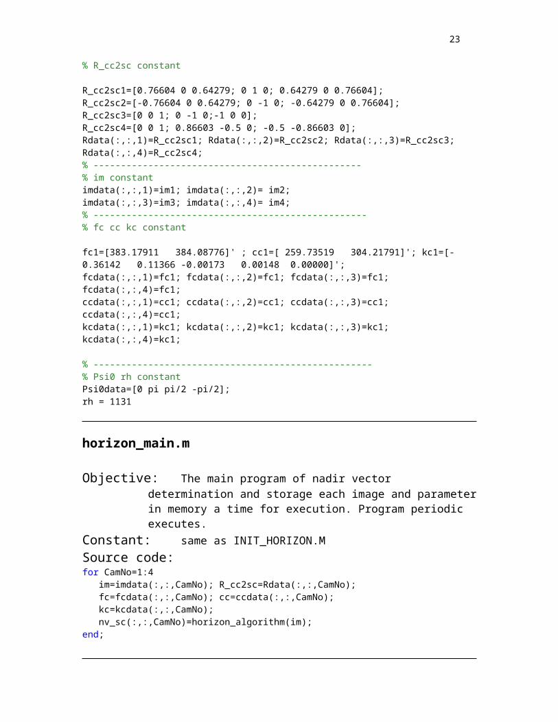
R_cc2sc1=[0.76604 0 0.64279; 0 1 0; 0.64279 0 0.76604];R_cc2sc2=[-0.76604 0 0.64279; 0 -1 0; -0.64279 0 0.76604];R_cc2sc3=[0 0 1; 0 -1 0;-1 0 0];R_cc2sc4=[0 0 1; 0.86603 -0.5 0; -0.5 -0.86603 0];Rdata(:,:,1)=R_cc2sc1; Rdata(:,:,2)=R_cc2sc2; Rdata(:,:,3)=R_cc2sc3;Rdata(:,:,4)=R_cc2sc4; % -------------------------------------------------% im constantimdata(:,:,1)=im1; imdata(:,:,2)= im2; imdata(:,:,3)=im3; imdata(:,:,4)= im4; % --------------------------------------------------% fc cc kc constant
fc1=[383.17911 384.08776]' ; cc1=[ 259.73519 304.21791]'; kc1=[-0.36142 0.11366 -0.00173 0.00148 0.00000]';
Horizon algorithm(horizon_algorithm.m)
Initial horizon(init_horizon.m)
Nadir vector(nv_sc)
Periodic run program
Storage image by image in SimRam i=1:4

19
fcdata(:,:,1)=fc1; fcdata(:,:,2)=fc1; fcdata(:,:,3)=fc1; fcdata(:,:,4)=fc1; ccdata(:,:,1)=cc1; ccdata(:,:,2)=cc1; ccdata(:,:,3)=cc1; ccdata(:,:,4)=cc1;kcdata(:,:,1)=kc1; kcdata(:,:,2)=kc1; kcdata(:,:,3)=kc1; kcdata(:,:,4)=kc1;
% ---------------------------------------------------% Psi0 rh constantPsi0data=[0 pi pi/2 -pi/2]; rh = 1131
horizon_main.m
Objective: The main program of nadir vector determination and storage each image and parameter in memory a time for execution. Program periodic executes.
Constant: same as INIT_HORIZON.MSource code:for CamNo=1:4
im=imdata(:,:,CamNo); R_cc2sc=Rdata(:,:,CamNo);fc=fcdata(:,:,CamNo); cc=ccdata(:,:,CamNo);kc=kcdata(:,:,CamNo);nv_sc(:,:,CamNo)=horizon_algorithm(im);
end;
horizon_algorithm.mObjective: Horizon algorithm runs the steps of algorithm to determine the sun vector. Global constant: R_cc2sc fc cc kc alphaH alphaL Psi0 rhInitial constant: - [a] is an initial value to begin counting the elements of edge point
(uv)Input: - [im] is matrix of image. Size (512x512) 8-bitsOutput: - [nv_sc] is nadir vector respected to satellite coordinate. Size (3x1) unit
vector.
Figure 4. Block diagram of horizon algorithm
Find edge (findedge.m)
Check shadow (check_shadow.m)
Loop of correct row and column- Low pass filter (lp.m) - Find level high and low- Normalize to binary (normal.m)- Count the signal (stepindex.m)- Check horizon (check_horizon.m)
Anti distortion (antid_inter.m)Subprogram-Computer anti-distortion (normalize.m)- Iterative method for compensation (comp_distortion_oulu.m)
Centroid or center (center.m)
Calculate cam coor (camco.m)
Calculate R int. respected to curr.
Nadir vector(nv_sc)
20
function [nv_sc]=horizon_algorithm(im)global R_cc2sc fc cc kc alphaH alphaL Psi0a=0; %initial horizontal point(uv) [correctRow,correctCol]=findedge(im); % find the edge ;if correctRow==0 & correctCol==0; nv_sc=[0; 0; 0]; break ;end;if correctRow>=1; for i=1:length(correctRow);j=[1:512]; data(i,:)=im(correctRow(i),j); lpdata(i,:)=lp(data(i,:)); high=max(lpdata(i,:)); % using ratio from low pass to avoid noise low=min(lpdata(i,:)); levelH=low + alphaH*(high-low); levelL=low + alphaL(high-low); nr(i,:)=normal(lpdata(i,:),levelH); edgenum(i,:)=stepindex(nr(i,:)); [correct_p,correct_nr]=check_horizon(edgenum,data(i,:),lpdata(i,:),nr(i,:),levelL); for k=1:length(correct_p(i)); a=a+1; UV(a,:)=[correctRow(i),correct_p(k)]; end; end;end;
if correctCol>=1; for i=1:length(correctCol);j=[1:512]; data(i,:)=(im(j,correctCol(i)))'; lpdata(i,:)=lp(data(i,:)); high=max(lpdata(i,:)); % using ratio from low pass to avoid noise low=min(lpdata(i,:)); levelH=low + alphaH*(high-low); levelL=low + alphaL*(high-low); nr(i,:)=normal(lpdata(i,:),levelH); edgenum=stepindex(nr(i,:)); [correct_p,correct_nr]=check_horizon(edgenum,data(i,:),lpdata(i,:),nr(i,:),levelL); for k=1:length(correct_p); a=a+1; UV(a,:)=[correct_p(k),correctCol(i)]; end; end;end; [Xp, Yp]= antid_inter(UV); % anti-distortioncent=center([Xp,Yp]); % calculate center point by persidou invert[shadow,Rrms]=check_shadow(cent,Xp,Yp); % check shadowswitch shadow
case '0' R1=R_cc2sc; % from geometry of camera
R2=camco(fc(2),cc(1),cc(2),Psi0,cent(1),cent(2),Rrms);R=R2*inv(R1);nv_sc=R*[0 0 1]'; % nadir vector reference to initial body fixed
coordinate case '1' nv_sc=[0; 0; 0] % no earth in image.

21
end;
findedge.m
Objective: Find edge by sampling the data. Using standard derivation to check appearing horizon. This program use STD=30.
Initial constant:- [a] is an initial value to begin counting the number of detecting time.- [b] is 1 ,which shows complete (1) or incomplete (0) scan.
Input: - [im] is matrix of image. Size (512x512) 8-bitsOutput: - [correctRow] is the correct row. Size integer vector (variable)
- [correctCol] is the correct column. Size integer vector (variable)Source code:
function [correctRow,correctCol]=findedge(im)a=0; % initial a=0 to count correct scanning lineb=1; % initial b=1 for completed information in column scan.correctCol=0; correctRow=0; % initail% Using standard division criterion to accept the edge.stdedge =30; % from experiment% stepscan=16;t=16:16:512; %To save flops give t(stepscan) =[16 32 48 ... 512]
for j=1:3;v=128*j; for i=1:32; sample(i,j)=im(t(i),v); end;
sample=double(sample); if std(sample(:,j))>stdedge; a=a+1; correctCol(a)=v; end;end; % second scanning: 4 cases a=0,1,and 2 % 2nd**cases a=2**(2 signals in col 128,256 or 384)% So scan line between 2 signals must get signal.% If it doesn't get the third signal, this program will reset b=0 if a==2; v=(correctCol(1)+correctCol(2))/2; for i=1:32; sample(i,1)=im(t(i),v); end if std(sample(:,1))>stdedge; a=a+1; correctCol(a)=v; end; if a~=3; b=0; end;end;% 2nd**cases a=1**(1 signal in col 128,256 or 384)% So scan line between left and right must get signal.% If it doesn't get the third signal, this program will reset b=0 if a==1; center=correctCol(1); % scan right of correct column
for j=1:2,v=center+16*j;for i=1:32;
sample(i,j)=im(t(i),v); end;

22
if std(sample(:,j))>stdedge; a=a+1; correctCol(a)=v; end; end; % scan left of correct column for j=1:2; v=center-16*j; for i=1:32; sample(i,j)=im(t(i),v); end; if std(sample(:,j))>stdedge; a=a+1; correctCol(a)=v; end; end; if a<3;checking enough information b=0; end; end;% ****end of column scan****
% 2nd**cases a=0**(no signal in col 128,256 and 384)% So scanning at row 128,256 and 384 if a==0|b==0 ; for i=1:3;u(i)=128*i; for j=1:32; sample(i,j)=im(u(i),t(j)); end; if std(sample(i,:))>stdedge; a=a+1; correctRow(a)=u(i); end; end;
if a>=3; b=1; else b=0; end;end;
% 3rd scanning for cases a<3 meaning don't have enough data.% __3__ % | | ** last scanning at Col#8,Row#8,Col#504,and Row #504% 1 2 If scan doesn't find edge, then image doesn't have horizon,% |__4__|
if a==0|b==0 ; s=[8,504]; % scan column for j=1:2; for i=1:32; sample(i,j)=im(t(i),s(j)); end; if std(sample(:,j))>stdedge; a=a+1; correctCol(a)=s(j); end; end; if correctCol(1)~=0; if correctCol(1)==504; sign=-1; else sign=1; end for i=1:2; correctCol(a+i)=correctCol(1)+sign*8*i; end;
23
end % scan row for j=1:2; for i=1:32; sample(i,j)=im(s(j),t(i)); end; if std(sample(:,j))>stdedge; a=a+1; correctRow(a)=s(j); end; end; if correctRow(1)~=0; if correctRow(1)==504; sign=-1; else sign=1; end for i=1:2; correctRow(a+i)=correctCol(1)+sign*8*i; end; end end;
lp.m (objective, input, output and source code is shown in page 13)normal.m (objective, input, output and source code is shown in page 13)stepindex.m (objective, input, output and source code is shown in page 13)
check_horizon.m
Objective: determine the correct point of edge and eliminate the noise from sun and non-smooth of land and ocean on horizon region.
Input: [edgenum] is the position of edge from normalized data. 1xN vector[data] is the real data from image. 1x512 integer vector
[lpdata] is the filtered data by low pass method. 1x512 vector [nr] is the normalize data. 1x512 binary vector[levelL] is the lowest level, which is criteria of elimination noise on horizon region
Output: [correct_p] is the correct point on the horizon image. 1xN integer Source code:Function correct_p =check_horizon(edgenum,data,lpdata,nr,levelL)
a=[1 edgenum 512];b=length(edgenum)+1;c=0;d=0; % initial dummydummy=a;if b>1; for i=1:b; cen=ceil((a(i)+a(i+1))/2); if nr(cen)==1 & data(cen)>=250; % check sun dummy(i)=0; dummy(i+1)=0; % 0 represents edge from noise

24
end; if nr(cen)==0; leng=a(i+1)-a(i); if leng<=10 | lpdata(cen)>levelL ; dummy(i)=0; dummy(i+1)=0; end; end; end;
for i=1:b; if dummy(i)>1 & dummy(i)~=512; % a(i)>0 & a(i)~=1 implies a(i)>1 d=1+d; correct_p(d)=dummy(i); end;
end; else correct_p=edgenum;end;
antidis_inter.m and subprogram normalize.m and comp_distortion_oulu.m(objective, input, output and source code are shown in page 14-15 )
center.m (objective, input, output and source code is shown in page 16)
check_shadow.m Objective: Checking shadow condition in image.Global constant: [rh] radius (pixel) of horizon. See shadow condition (Rev2)Input: [cent] is a center point of horizon. 2x1 vector
[Xp]and [Yp] are a point of arc on the circle. 1xN vectorOutput: [SHADOW] is a logical value, represented shadow appearing ('1') or non-
appearing ('0'). Size constant[Rrms] is root mean square of horizon radius. Size [1]
Source code:
function [shadow,Rrms]=check_shadow(cent,Xp,Yp)global rhleng=length(Xp);for i=1:leng R(i)= ((cent(1)-Xp(i))^2 + (cent(2)-Yp(i))^2)^0.5;end;Rrms=(sum(R.^2)/leng)^0.5;if Rrms< 0.7*rh | Rrms> 1.3*rh
shadow='1'; % shadow appearselse shadow='0'; % correct detectionend

25
camco.m
Objective: determines orthogonal coordinates of camera in Body Initial Coordinate (BIC) from image detection. This method is based on geometry and vector. The concepts are shown in Camera algorithm.doc
Input: [f] is focus length or fc(2). Size constant [1][uo] and [vo] is coordinate of (o)ptical axis or cc(1) and cc(2). Size is constant in pixel unit.
[Psi0] is the yaw angle of initial camera coordinate. Size constant [1][uc] and [vc] is a coordinate of (c)enter of circle or cent(1) and cent(2). Size constant in pixel units[r] is a radius of circle. Using RMS of R (Rrms). Size is constant [1] in pixel units.
Output: [xyzCC_BIC] is a unit vector of camera coordinate respected to Body Initial Coordinate (BIC)
Source code:function xyzCC_BIC=camco(f,uo,vo,Psi0,uc,vc,r)u=uo-uc;v=vo-vc; % dummy for saving flopsPO=((u)^2+(v)^2)^0.5;Theta2=atan(f/PO);SP=f*cos(Theta2); Theta1=atan(r/SP);Theta=(2*pi)-Theta2-Theta1;Psi1=atan(u/v);Psi=Psi1+Psi0;%(small vector represents as a unit vector)y1CC_BIC=[-cos(Psi)*cos(Theta); -sin(Psi)*cos(Theta); sin(Theta)];zCC_BIC=[cos(Psi)*sin(Theta); sin(Psi)*sin(Theta); cos(Theta)];x1CC_BIC=cross(y1CC_BIC,zCC_BIC);ratio=(v/u);Y_CC_BIC=y1CC_BIC+ratio*(x1CC_BIC);yCC_BIC= Y_CC_BIC/((Y_CC_BIC(1))^2+(Y_CC_BIC(2))^2+(Y_CC_BIC(3))^2)^0.5;xCC_BIC=cross(yCC_BIC,zCC_BIC);xyzCC_BIC=[xCC_BIC(1) yCC_BIC(1) zCC_BIC(1); xCC_BIC(2) yCC_BIC(2) zCC_BIC(2); xCC_BIC(3) yCC_BIC(3) zCC_BIC(3)];
26
Part 3: Captures Image
After image from space is downlink to ground station, we use Gaussian filter to eliminate the noise image. Another method is offset correction from Fuga’s software. Now we cannot apply this method to filter the noise from capture image. ** All M codes in this part don’t have to change to C code. **
Gaussian filterObjective: filter the image by using Gaussian filter.Input: a noisy imageOutput: clear imageSource code
% Parameters of the Gaussian filter:n1=10;sigma1=3;n2=10;sigma2=3;theta=0;[y,map]=imread('nonoffset1.bmp'); filter1=d2gauss(n1,sigma1,n2,sigma2,theta); % Gaussian filter gf=conv2(y,filter1,'same');imagesc(gf1);title('Gaussian filter (sigma=3)');colormap(gray);%%%%%%%%%%%%%% End of the main.m file %%%%%%%%%%%%%%%
% Function "d2gauss.m":% This function returns a 2D Gaussian filter with size n1*n2; theta is % the angle that the filter rotated counter clockwise; and sigma1 and sigma2% are the standard deviation of the Gaussian functions.function h = d2gauss(n1,std1,n2,std2,theta)r=[cos(theta) -sin(theta); sin(theta) cos(theta)];for i = 1 : n2 for j = 1 : n1 u = r * [j-(n1+1)/2 i-(n2+1)/2]'; h(i,j) = gauss(u(1),std1)*gauss(u(2),std2); endendh = h / sqrt(sum(sum(h.*h)));
% Function "gauss.m":function y = gauss(x,std)y = exp(-x^2/(2*std^2)) / (std*sqrt(2*pi));
27
Part 4: Accessories Code
This part shows the general source codes to analysis the image, such as angle between two vector, sub-pixel method, 1-D Gaussian filer and edge detection and cut off the lower intensity. . ** All M codes in this part don’t have to change to C code. **
angle between two vectorsObjective: determine the different angle between two vectorsInput: [a] and [b] is a unit vector . 3x1 unit vector
Output: [a_rad] and [a_deg] angle in degree and radius
angle=dot(a,b)/norm(a)/norm(b);a_rad=acos(angle), a_deg=(angle)*180/pi
sub-pixel methodObjective: determine the center or centroid point by using sub-pixel.Input: [im] a image of sun. 512x 512 (8 bits)
[U] and [V] a maximum intensity point on uv-axis. Integer number Output: [point] a maximum intensity point by sub-pixel methodNote: This source code is developed from sub-pixel edge detection, which
determines the position of edge with 1/50 pixel. See Devernay [1995]2.However, this code is modified to determine the centroid and don’t have experiment on this code. On the estimated accuracy, it should give the accuracy between ¼ to 1/50 pixel. Then I assume accuracy is 1/4 pixel for feature analysis data.
Source code:
function point =subpixel(im,U,V)global ta=im(U-1:U+1,V-1:V+1); a=double(a);t=0; % initialboundary=bsubpix(a);cent=center(boundary); % calculate center point by persidou invertpoint=[U+cent(1) V+cent(2)]
Sub program:function boundary=bsubpix(A,b)% BSUBPIX determines the boundary of maximun point. % This method is developed from 1/50 pixel accuracy edge detection.global tif nargin < 2;alpha=0.95;b=0; % Should use alpha=0.95else alpha=b;end; A=double(A); % constant
2 F. DEVERNAY, A Non-Maxima Suppression Method for Edge Detection with Sub-Pixel Accuracy, RR 2724, INRIA, nov. 1995 (PDF, PS) Download from ftp://ftp.inria.fr/INRIA/publication/publi-pdf/RR/RR-2724.pdf

28
A11=A(1,1); A12=A(1,2); A13=A(1,3);A21=A(2,1); A22=A(2,2); A23=A(2,3);A31=A(3,1); A32=A(3,2); A33=A(3,3); Co(1,:)=polyfit([-1 0 1],[A11 A12 A13],2); % Upper LineCo(2,:)=polyfit([-1 0 1],[A13 A23 A33],2); % Right Line Co(3,:)=polyfit([-1 0 1],[A31 A32 A33],2); % Lower LineCo(4,:)=polyfit([-1 0 1],[A11 A21 A31],2); % Left Lineleng=[1 2^0.5 1 2^0.5]; Icen=A22; a=0;
% find which line is Max Intensity coef(1,:)=polyfit([-leng(1) 0 leng(1)],[A12 A22 A32],2); coef(2,:)=polyfit([-leng(2) 0 leng(2)],[A31 A22 A13],2);
coef(3,:)=polyfit([-leng(3) 0 leng(3)],[A21 A22 A23],2);coef(4,:)=polyfit([-leng(4) 0 leng(4)],[A11 A22 A33],2);
for i=1:4 PoMax(i)=-coef(i,2)/2/coef(i,1); I(i)=coef(i,1)*PoMax(i)^2+coef(i,2)*PoMax(i)+coef(i,3);endImax=max(I);% quadatic 1 & 3for i=1:6
y=[-1+0.2*(i-1) 0 1-0.2*(i-1)]; Int=[Co(1,1)*y(1)^2 + Co(1,2)*y(1) + Co(1,3), Icen ...
Co(3,1)*y(3)^2 + Co(3,2)*y(3) + Co(3,3)];leng=[-(1+y(1)^2)^0.5 0 (1+y(1)^2)^0.5 ]; HalfLeng(i)=abs(leng(1))/2;coef=polyfit(leng,Int,2);
rt(:,i)=roots([coef(1) coef(2) (coef(3)-alpha*Imax)]); r(i,:)=[rt(1,i) rt(2,i)]; theta(i)=atan((-1+0.2*(i-1))/-1) + pi; if (isreal(r(i,:))==1) &(abs(r(i,1))<= HalfLeng(i)); a=a+1; boundary(a,:)=[r(i,1)*abs(cos(theta(i))) r(i,1)*abs(sin(theta(i)))]; end if (isreal(r(i,:))==1) & (abs(r(i,2))<= HalfLeng(i)); a=a+1; boundary(a,:)=[r(i,2)*abs(cos(theta(i))) r(i,2)*abs(sin(theta(i)))]; end end % quadatic 2&4 for i=7:11
y=[-1+0.2*(i-1) 0 1-0.2*(i-1)]; Int=[Co(1,1)*y(1)^2 + Co(1,2)*y(1) + Co(1,3), Icen ...
Co(3,1)*y(3)^2 + Co(3,2)*y(3) + Co(3,3)];leng=[-(1+y(1)^2)^0.5 0 (1+y(1)^2)^0.5 ]; HalfLeng(i)=abs(leng(1))/2;coef=polyfit(leng,Int,2);
rt(:,i)=roots([coef(1) coef(2) (coef(3)-alpha*Imax)]); r(i,:)=[rt(1,i) rt(2,i)]; theta(i)=atan((-1+0.2*(i-1))/-1) + pi; if (isreal(r(i,:))==1) &(abs(r(i,1))<= HalfLeng(i)); a=a+1; boundary(a,:)=[r(i,1)*(cos(theta(i))) r(i,1)*(sin(theta(i)))]; end if (isreal(r(i,:))==1) & (abs(r(i,2))<= HalfLeng(i)); a=a+1; boundary(a,:)=[r(i,2)*(cos(theta(i))) r(i,2)*(sin(theta(i)))]; end end% quadatic 2&4for i=12:16; x=[-1+0.2*(i-11) 0 1-0.2*(i-11)];
29
Int=[Co(4,1)*x(1)^2 + Co(4,2)*x(1) + Co(4,3), Icen ... Co(2,1)*x(3)^2 + Co(2,2)*x(3) + Co(2,3)]; leng=[-(1+x(1)^2)^0.5 0 (1+x(1)^2)^0.5 ]; HalfLeng(i)=abs(leng(1))/2; coef=polyfit(leng,Int,2); rt(:,i)=roots([coef(1) coef(2) (coef(3)-alpha*Imax)]); r(i,:)=[rt(1,i) rt(2,i)]; if i==16; theta(i)= pi/2; else theta(i)=atan(1 /(-1+0.2*(i-11)))+pi; end if (isreal(r(i,:))==1) &(abs(r(i,1))<= HalfLeng(i)); a=a+1; boundary(a,:)=[r(i,1)*cos(theta(i)) r(i,1)*sin(theta(i))];end if (isreal(r(i,:))==1) & (abs(r(i,2))<= HalfLeng(i)); a=a+1; boundary(a,:)=[r(i,2)*cos(theta(i)) r(i,2)*sin(theta(i))]; end end
% quadatic 1&3 for i=17:21; x=[-1+0.2*(i-11) 0 1-0.2*(i-11)]; Int=[Co(4,1)*x(1)^2 + Co(4,2)*x(1) + Co(4,3), Icen ... Co(2,1)*x(3)^2 + Co(2,2)*x(3) + Co(2,3)]; leng=[-(1+x(1)^2)^0.5 0 (1+x(1)^2)^0.5 ]; HalfLeng(i)=abs(leng(1))/2; coef=polyfit(leng,Int,2); rt(:,i)=roots([coef(1) coef(2) (coef(3)-alpha*Imax)]); r(i,:)=[rt(1,i) rt(2,i)]; theta(i)=atan(1/(-1+0.2*(i-11))); if (isreal(r(i,:))==1) &(abs(r(i,1))<= HalfLeng(i)); a=a+1; boundary(a,:)=[r(i,1)*cos(theta(i)) r(i,1)*sin(theta(i))];end if (isreal(r(i,:))==1) & (abs(r(i,2))<= HalfLeng(i)); a=a+1; boundary(a,:)=[r(i,2)*cos(theta(i)) r(i,2)*sin(theta(i))]; end endif a<1;t=t+1;if t==10;disp('error'); break;end newalpha=alpha+0.045/10^(t); boundary=bsubpix(A,newalpha); end;
cutoff.mObjective: makes image to show only higher intensity for analysis the sun.Input: [image] is an image.
[cut] is the highest intensity level, which be changed to zero. Output: [A_cut] is an image after program cut off the intensity.function [A_cut]=cutoff(image,cut)for i=1:size(image,1); for j=1:size(image,2); % cut=254 if image(i,j)<= cut A_cut(i,j)=0; else A_cut(i,j)=image(i,j); end endend
1-D Gaussian filer and edge detection from ideal edge
30
Objective: show the sample the edge by using 1D gaussian filter and edge detection by local maximum of gradient and Laplacian of a Gaussian (LOG) edge detection. This method will give accuracy 1/50 pixel.
Note: To apply this code in a real image from Fuga15D without offset-correct, this code have to have more code to filter noise and using human notice to detect the edge position. Due to non-uniform noise, the gradient and Laplacian rapidly change the signal. By the way, this code can determine what the good alpha of threshold ratio edge detection is.
Source code:% edgesample.m % makes a step function to represent ideal edge% v0.1 date June 6,2001Int(1:32)=0;Int(33:96)=1;Int(97:128)=0; y=[Int(1:32) 1 Int(33:96) 0 Int(97:128)];x=[1:32 32 33:96 96 97:128]; figure(1);subplot(2,2,1);plot(x,y);axis([0 128 -0.2 1.2]);gridtitle('a) Step Function Representing Edge'); xlabel('Length');ylabel('intensity'); for i=1:21;z(i)=(cos((i-1)*pi/20)+1)/2;endysys=Int;for uppoint=[32] for downpoint=[96] ysys(uppoint-10:uppoint+10)=1-z; ysys(downpoint-10:downpoint+10)=z; end ;end% Gaussian Filtersigma=3;leng=11;gaussFun=d1gauss(leng,sigma); % need GAUSS.m in working directoryy_conv=conv(ysys,gaussFun); le=length(y_conv); %resulting vector is length LENGTH(A)+LENGTH(B)-1.be=(leng+1)/2; en=le-(leng-1)/2;y_gauss=y_conv(be:en);subplot(2,2,2);plot(y_gauss);axis([0 128 -0.2 1.2]);gridtitle('b) Ideal Edge from Camera Image'); xlabel('length');ylabel('intensity'); % Gradient based edge detectiony_grad=gradient(y_gauss);subplot(2,2,3);plot(y_grad);axis([0 128 -0.1 0.1]);grid;title('c) Gradient Based Edge Detection'); xlabel('length');ylabel('intensity/pixel'); % Laplacian of a Gaussian (LOG) edge detection y_log=gradient(y_grad);subplot(2,2,4);plot(y_log);axis([0 128 -0.01 0.01]);grid;title('d) Laplacian of Gaussian Edge Detection');xlabel('Length');ylabel('intensity/pixel^2');
Subprogram: d1gauss.m% Function "d1gauss.m":% This function use a 2D Gaussian filter with size n1.function h = d1gauss(n1,std1)for i = 1 : n1 ; u = [i-(n1+1)/2]; h(i) = gauss(u,std1);endSubprogram: d1gauss.m% Function "gauss.m":function y = gauss(x,std)

31
y = exp(-x^2/(2*std^2)) / (std*sqrt(2*pi));
Image from this source code:
Figure 5 Ideal edge detection by 1-D Gaussian filter, gradient based and Laplacian of Gaussian edge detection
32
Analysis the source code and some experiment
This part shows performance of sun algorithm (table1) and horizon algorithm (table2). Sun algorithm takes about 7,000- 10,000 flops a sun image to determine sun vector. For no sun case, sun algorithm takes about 60 flops. Other, horizon algorithm takes about 23,000 flops a horizon image to determine nadir vector. For no horizon case, horizon algorithm takes about 1,346 flops.
Function Flops % of total flops
Main sun_alogithm.m 9539
Sub checksun.m 17 0.18swsize.m 10 0.10
rowscan.m 12 0.13lp.m 3630 38.05
normal.m 0 0.00stepindex.m * 630 6.60change.m * 150 1.57
antid_inter.m 4011 42.05center.m 1122 11.76sunvec.m 15 0.16cc2sc.m 18 0.19
* Estimated flops because data is variable- No sun case takes 60 flops
Table 1 Analysis program performance of sun algorithm of image b17.bmp
Table 2 Analysis program performance of horizon algorithm of image bright_pic.bmp.
Experiment of sun algorithm test the real image of sun, which capture form outdoor. The images have two series: series (a) and (b) in figure 6. The Fuga15D images in series (a) are manual grain control with neutral density filter. The images in series (b) are automatic grain control without any filter.
Analysis the 20 images fond the angle error between (a) and (b) is about 1.1 degree at 3 in Table 3. (Note: this numerical error doesn’t count the image b07.bmp because sun appears in boundary and give a huge error). The undetectable error or extreme error will show out, when the sun appear near by boundary, such image b06, b07 and b16. We can reduce the error by normalizing data at 245 gray-level-intensity.
Future, the horizon analysis and experiment will revise later.
Function Flops % of total flops
main horizon_alogithm.m 23319
Sub findedge.m 408 1.75lp.m 6135x3 79.93
normal.m 0 0.00stepindex.m * 1036x3 13.33
check_horizon.m* 75x3 0.96antid_inter.m 628 2.96
center.m 241 1.03check_shadow.m 36 0.15
cam_co.m 77 0.33sunvec.m 15 0.06cc2sc.m 18 0.08
* Estimated flops because data is variable.- No horizon case takes 1346 flops

33
b01.bmp b02.bmp b03.bmp b04.bmp b05.bmp
b06.bmp b07.bmp b08.bmp b09.bmp b10.bmp
b11.bmp b12.bmp b13.bmp b14.bmp b15.bmp
b16.bmp b17.bmp b18.bmp b19.bmp b20.bmp
a01.bmp a02.bmp a03.bmp a04.bmp a05.bmp
a06.bmp a07.bmp a08.bmp a09.bmp a10.bmp
a11.bmp a12.bmp a13.bmp a14.bmp a15.bmp
zoom picture from a series image
Figure 6 Experiment of sun images for analysis sun algorithm

34
Image No
center sub-pixel method
sun vectorerror error flops time
u v x y z (rad) (deg) (sec)1 61.2317 103.8806 -0.4844 -0.4851 0.7281 0.0101 0.5803 7438 0.332 41.945 144.9822 -0.5346 -0.3827 0.7535 0.015 0.8621 7802 0.383 476.9663 24.9407 0.4823 -0.6209 0.618 0.0017 0.0993 7344 0.384 398.0113 30.0029 0.3334 -0.6483 0.6845 0.0093 0.534 9329 0.445 334.0091 36.1113 0.1819 -0.6533 0.7349 0.0043 0.2467 6859 0.386 171.0489 29.0159 note *1* - - - -7 249.9132 5.9419 -0.0332 -0.6132 0.7892 0.1435 8.2209 2465 0.228 503 100 0.5683 -0.4735 0.6729 0.0142 0.8142 5990 0.339 443 107 0.45743 -0.48654 0.74433 0.008571 0.49109 4914 0.2710 376.9401 114.9775 0.2921 -0.4741 0.8307 0.0012 0.0691 7118 0.3311 268.0801 125.9846 0.0403 -0.4557 0.8892 0.0202 1.1597 7327 0.3912 222.9274 128.9956 -0.0884 -0.4461 0.8906 0.0058 0.3345 8320 0.3813 137.9756 138.0235 -0.3126 -0.4126 0.8556 0.0078 0.4442 10099 0.4414 70.0056 107.0238 -0.452 -0.4825 0.7503 0.0221 1.2659 7277 0.3315 50.0104 108.0121 -0.5048 -0.4801 0.7174 0.012 0.6898 9163 0.3816 14.9859 169.0387 note *2* - - - -17 57.8693 162 -0.50551 -0.35341 0.78712 0.000898 0.051443 9539 0.3818 80.6782 158.9879 -0.43674 -0.37218 0.81899 0.016061 0.92025 7160 0.3319 87.3803 157.0102 -0.43769 -0.36148 0.82326 0.008516 0.48792 9068 0.3920 204.8845 143.6602 -0.13851 -0.40724 0.90276 0.001307 0.07488 8025 0.33
6** -0.21653 -0.66337 0.71628 0.009335 0.53488 8654 0.387** -0.02638 -0.71718 0.69639 0.003983 0.2282 3685 0.22
*1* Data is error when use a normalized level at 250*2* Data is error because sun appear near boundary.** Re-test by Normalizing data at level 245
Table 3 Analysis program performance of sun algorithm 20 images.