Embed Size (px)
Citation preview

Utah State Amendments for the 2015 IRC
Courtesy of the


In IRC, Section R102, a new Section R102.7.2 is added as follows:
"R102.7.2 Physical change for bedroom window egress.
A structure whose egress window in an existing bedroom is smaller than required by this code,
and that complied with the construction code in effect at the time that the bedroom was finished,
is not required to undergo a physical change to conform to this code if the change would
compromise the structural integrity of the structure or could not be completed in accordance with
other applicable requirements of this code, including setback and window well requirements."
Insert after page 2


(2) In IRC, Section 109:
(a) A new IRC, Section 109.1.5, is added as follows:
"R109.1.5 Weather-resistant exterior wall envelope inspections. An inspection shall be
made of the weather-resistant exterior wall envelope as required by Section R703.1 and flashings
as required by Section R703.8 to prevent water from entering the weather-resistive barrier."
(b) The remaining sections are renumbered as follows: R109.1.6 Other inspections; R109.1.6.1
Fire- and smoke-resistance-rated construction inspection; R109.1.6.2 Reinforced masonry,
insulating concrete form (ICF) and conventionally formed concrete wall inspection; and
R109.1.7 Final inspection.
Insert after page 6


IRC, Section R114.1, is deleted and replaced with the following:
"R114.1 Notice to owner. Upon notice from the building official that work on any building or
structure is being prosecuted contrary to the provisions of this code or other pertinent laws or
ordinances or in an unsafe and dangerous manner, such work shall be immediately stopped. The
stop work order shall be in writing and shall be given to the owner of the property involved, or to
the owner's agent or to the person doing the work; and shall state the conditions under which
work will be permitted to resume."
Insert after page 8


In IRC, Section R202, the following definition is added:
"CERTIFIED BACKFLOW PREVENTER ASSEMBLY TESTER: A person who has
shown competence to test Backflow prevention assemblies to the satisfaction of the authority
having jurisdiction under Utah Code, Subsection 19-4-104(4)."
"CONDITIONED SPACE" is modified by deleting the words at the end of the sentence
"being heated or cooled by any equipment or appliance" and replacing them with the following:
"enclosed within the building thermal envelope that is directly heated or cooled, or indirectly
heated or cooled by any of the following means:
1. Openings directly into an adjacent conditioned space.
2. An un-insulated floor, ceiling or wall adjacent to a conditioned space.
3. Un-insulated duct, piping or other heat or cooling source within the space."
"CROSS CONNECTION. Any physical connection or potential connection or arrangement
between two otherwise separate piping systems, one of which contains potable water and the
other either water of unknown or questionable safety or steam, gas, or chemical, whereby there
exists the possibility for flow from one system to the other, with the direction of flow depending
on the pressure differential between the two systems (see "Backflow, Water Distribution")."
Insert after page 12


In IRC, Section 202, in the definition for gray water a comma is inserted after the word
"washers"; the word "and" is deleted; and the following is added to the end: "and clear water
wastes which have a pH of 6.0 to 9.0; are non-flammable; non-combustible; without
objectionable odors; non-highly pigmented; and will not interfere with the operation of the sewer
treatment facility."
New definition will read;
Gray Water. Waste discharged from lavatories, bathtubs, showers, clothes washers, laundry
trays, and clear water wastes which have a pH of 6.0 to 9.0; are non-flammable; non-
combustible; without objectionable odors; non-highly pigmented; and will not interfere with the
operation of the sewer treatment facility
Insert after page 16


In IRC, Section R202, the definition of "Potable Water" is deleted and replaced with the
following:
"POTABLE WATER. Water free from impurities present in amounts sufficient to cause
disease or harmful physiological effects and conforming to the Utah Code, Title 19, [Chapters]
Chapter 4, Safe Drinking Water Act, and Title 19, Chapter 5, Water 1267 Quality Act, and the
regulations of the public health authority having jurisdiction."
Insert after page 20

IRC, Figure R301.2(5), is deleted and replaced with Table R301.2(5a) and Table
R301.2(5b) as follows:
Beaver 43 63 6.2
Box Elder 43 63 5.2
Cache 50 63 4.5
Carbon 43 63 5.2
Daggett 43 63 6.5
Davis 43 63 4.5
Duchesne 43 63 6.5
Emery 43 63 6.0
Garfield 43 63 6.0
Grand 36 63 6.5
Iron 43 63 5.8
Juab 43 63 5.2
Kane 36 63 5.7
Millard 43 63 5.3
Morgan 57 63 4.5
Piute 43 63 6.2
Rich 57 63 4.1
Salt Lake 43 63 4.5
San Juan 43 63 6.5
Sanpete 43 63 5.2
Sevier 43 63 6.0
Summit 86 63 5.0
Tooele 43 63 4.5
"TABLE NO. R301.2(5a)
STATE OF UTAH - REGIONAL SNOW LOAD FACTORS
COUNTY Po S Ao

Uintah 43 63 7.0
Utah 43 63 4.5
Wasatch 86 63 5.0
Washington 29 63 6.0
Wayne 36 63 6.5
Weber 43 63 4.5
TABLE NO. R301.2(5b)
REQUIRED SNOW LOADS FOR SELECTED UTAH CITIES AND TOWNS1,2
The following jurisdictions require design snow load values that differ from the Equation in
the Utah Snow Load Study.
County City Elevation Ground Snow
Load (psf)
Roof Snow
Load (psf) 6
Carbon Price3
All other county locations5
5550
--
43
--
30
--
Davis Fruit Heights3 4500 - 4850 57 40
Emery Green River3 4070 36 25
Garfield Panguitch3 6600 43 30
Rich Woodruff3
Laketown4
Garden City5
Randolph4
6315
6000
--
6300
57
57
--
57
40
40
--
40
San Juan Monticello3 6820 50 35
Summit Coalville3
Kamas4
5600
6500
86
114
60
80
Tooele Tooele3 5100 43 30
Utah Orem3
Pleasant Grove4
Provo5
4650
5000
--
43
43
--
30
30
--

Insert after page 40
Wasatch Heber5 -- -- --
Washington Leeds3
Santa Clara3
St. George3
All other county locations5
3460
2850
2750
--
29
21
21
--
20
15
15
--
Wayne Loa3 7080 43 30
1The IRC requires a minimum live load -- See R301.6.
2This table is informational only in that actual site elevations may vary. Table is only valid
if site elevation is within 100 feet of the listed elevation. Otherwise, contact the local
Building Official.
3Values adopted from Table VII of the Utah Snow Load Study
4Values based on site-specific study. Contact local Building Official for additional
information.
5Contact local Building Official.
6Based on Ce =1.0, Ct =1.0 and Is =1.0"


IRC, Section R301.6, is deleted and replaced with the following:
"R301.6 Utah Snow Loads. The snow loads specified in Table R301.2 (5b) shall be used for
the jurisdictions identified in that table. Otherwise, the ground snow load, Pg, to be used in the
determination of design snow loads for buildings and other structures shall be determined by
using the following formula: Pg = (Po2 + S2(A-Ao)2)0.5 for A greater than Ao, and Pg = Po for
A less than or equal to Ao.
WHERE:
Pg = Ground snow load at a given elevation (psf);
Po = Base ground snow load (psf) from Table No. R301.2(5a);
S = Change in ground snow load with elevation (psf/100 ft.) From Table No. R301.2 (5a);
A = Elevation above sea level at the site (ft./1,000);
Ao = Base ground snow elevation from Table R301.2 (5a) (ft./1,000).
The building official may round the roof snow load to the nearest 5 psf. The ground snow load,
Pg, may be adjusted by the building official when a licensed engineer or architect submits 1338
data substantiating the adjustments. Where the minimum roof live load in accordance
with Table R301.6 is greater than the design roof snow load, such roof live load shall be used for
design, however, it shall not be reduced to a load lower than the design roof snow load. Drifting
need not be considered for roof snow loads less than 20 psf."
Insert after page 50


In IRC, Section R302.5
the words "self-closing device" are deleted and replaced with "self-latching hardware".
Place after page 52


IRC, Section R302.13, is deleted
Place after page 54

In IRC, Section R303.4
the number "5" is changed to "3" in the first sentence.
Place after page 56


IRC, Sections R311.7.4
R 311.7.4 through R311.7.5.3, are deleted and replaced with the following:
"R311.7.4 Stair treads and risers. R311.7.5.1 Riser height. The maximum riser height shall be 8
inches (203 mm). The riser shall be measured vertically between leading edges of the adjacent
treads. The greatest riser height within any flight of stairs shall not exceed the smallest by more
than 3/8 inch (9.5 mm).
R311.7.5.2 Tread depth.
The minimum tread depth shall be 9 inches (228 mm).
The tread depth shall be measured horizontally between the vertical planes of the foremost
projection of adjacent treads and at a right angle to the tread's leading edge. The greatest
tread depth within any flight of stairs shall not exceed the smallest by more than 3/8 inch (9.5
mm). Winder treads shall have a minimum tread depth of 10 inches (254 mm) measured as
above at a point 12 inches (305 mm) from the side where the treads are narrower. Winder
treads shall have a minimum tread depth of 6 inches (152 mm) at any point. Within any
flight of stairs, the greatest winder tread depth at the 12-inch (305 mm) walk line shall not
exceed the smallest by more than 3/8 inch (9.5 mm).
R311.7.5.3 Profile.
The radius of curvature at the leading edge of the tread shall be no greater than 9/16 inch
(14.3 mm). A nosing not less than 3/4 inch (19 mm) but not more than 1 1/4 inches (32 mm)
shall be provided on stairways with solid risers. The greatest nosing projection shall not
exceed the smallest nosing projection by more than 3/8 inch (9.5 mm) between two stories,
including the nosing at the level of floors and landings. Beveling of nosing shall not exceed
1/2 inch (12.7 mm). Risers shall be vertical or sloped from the underside of the leading edge
of the tread above at an angle not more than 30 degrees (0.51 rad) 1380 from the vertical.
Open risers are permitted, provided that the opening between treads does not permit the
passage of a 4-inch diameter (102 mm) sphere.
Exceptions.
1. A nosing is not required where the tread depth is a minimum of 10 inches (254 mm).
2. The opening between adjacent treads is not limited on stairs with a total rise of 30
inches(762 mm) or less."
Place after page 64


IRC, Section R312.2,
R312.2 is deleted.
Place after page 66

IRC, Section R313.1
R313.1 through R313.2.1, are deleted and replaced with the following: "R313.1 Design
and installation. When installed, automatic residential fire sprinkler systems for
townhouses or one- and two-family dwellings shall be designed and installed in accordance
with Section P2904 or NFPA 13D."
Place after page 66

IRC Section 315.3,
The following words are added to the first sentence after the word "installed": "on each level of
the dwelling unit and".
IRC, Section R315.5,
A new exception, 3, is added as follows:
"3. Hard wiring of carbon monoxide alarms in existing areas shall not be required where
the alterations or repairs do not result in the removal of interior wall or ceiling finishes
exposing the structure, unless there is an attic, crawl space or basement available which
could provide access for hard wiring, without the removal of interior finishes."
IRC, Section R315.7, is added as follows:
"R315.7 Interconnection. Where more than one carbon monoxide alarm is required to be
installed within an individual dwelling unit in accordance with Section R315.1, the alarm
devices shall be interconnected in such a manner that the actuation of one alarm will
activate all of the alarms in the individual unit. Physical interconnection of smoke alarms
shall not be required where listed wireless alarms are installed and all alarms sound upon
activation of one alarm.
Exception: Interconnection of carbon monoxide alarms in existing areas shall not be
required where alterations or repairs do not result in removal of interior wall or ceiling
finishes exposing the structure, unless there is an attic, crawl space or basement available
which could provide access for interconnection without the removal of interior finishes."
Place after page 68


In IRC, Section R403.1.6, a new Exception 3 is added as follows:
"3. When anchor bolt spacing does not exceed 32 inches (813 mm) apart, anchor bolts may be
placed with a minimum of two bolts per plate section located not less than 4 inches (102 mm)
from each end of each plate section at interior bearing walls, interior braced wall lines, and at all
exterior walls."
In IRC, Section R403.1.6.1, a new exception is added at the end of Item 2 and Item 3 as follows:
"Exception: When anchor bolt spacing does not exceed 32 inches (816 1424 mm) apart, anchor
bolts may be placed with a minimum of two bolts per plate section located not less than 4 inches
(102 mm) from each end of each plate section at interior bearing walls, interior braced wall lines,
and at all exterior walls."
Place after page 88


In IRC, Section R404.1, a new exception is added as follows:
"Exception: As an alternative to complying with Sections R404.1 through R404.1.5.3, concrete
and masonry foundation walls may be designed in accordance with IBC Sections 1807.1.5 and
1807.1.6 as amended in Section 1807.1.6.4 and Table 1807.1.6.4 under these rules."
Place after page 100

2015 IECC Commercial and
Residential Utah State Amendments
Draft Copy - 04/15/2016
2015 IECC
®
INTERNATIONAL
Energy Conservation Code®
CODE ALERT! Sign up now to receive critical code updates and
free access to videos, book excerpts and training
resources.
Signup is easy, subscribe now! www.iccsafe.org/alerts

2015 International Energy Conservation Code®
First Printing: May 2014
ISBN: 978-1-60983-486-9 (soft-cover edition)
COPYRIGHT © 2014
by
INTERNATIONAL CODE COUNCIL, INC.
Date of First Publication: May 30, 2014
ALL RIGHTS RESERVED. This 2015 International Energy Conservation Code® is a copyrighted work owned by the Interna- tional Code Council, Inc. Without advance written permission from the copyright owner, no part of this book may be repro- duced, distributed or transmitted in any form or by any means, including, without limitation, electronic, optical or mechanical means (by way of example, and not limitation, photocopying, or recording by or in an information storage retrieval system). For information on permission to copy material exceeding fair use, please contact: Publications, 4051 West Flossmoor Road, Coun- try Club Hills, IL 60478. Phone 1-888-ICC-SAFE (422-7233).
Trademarks: “International Code Council,” the “International Code Council” logo and the “International Energy Conservation Code” are trademarks of the International Code Council, Inc.
PRINTED IN THE U.S.A.

2015 INTERNATIONAL ENERGY CONSERVATION CODE® R-27
2015 INTERNATIONAL ENERGY CONSERVATION CODE® R-27
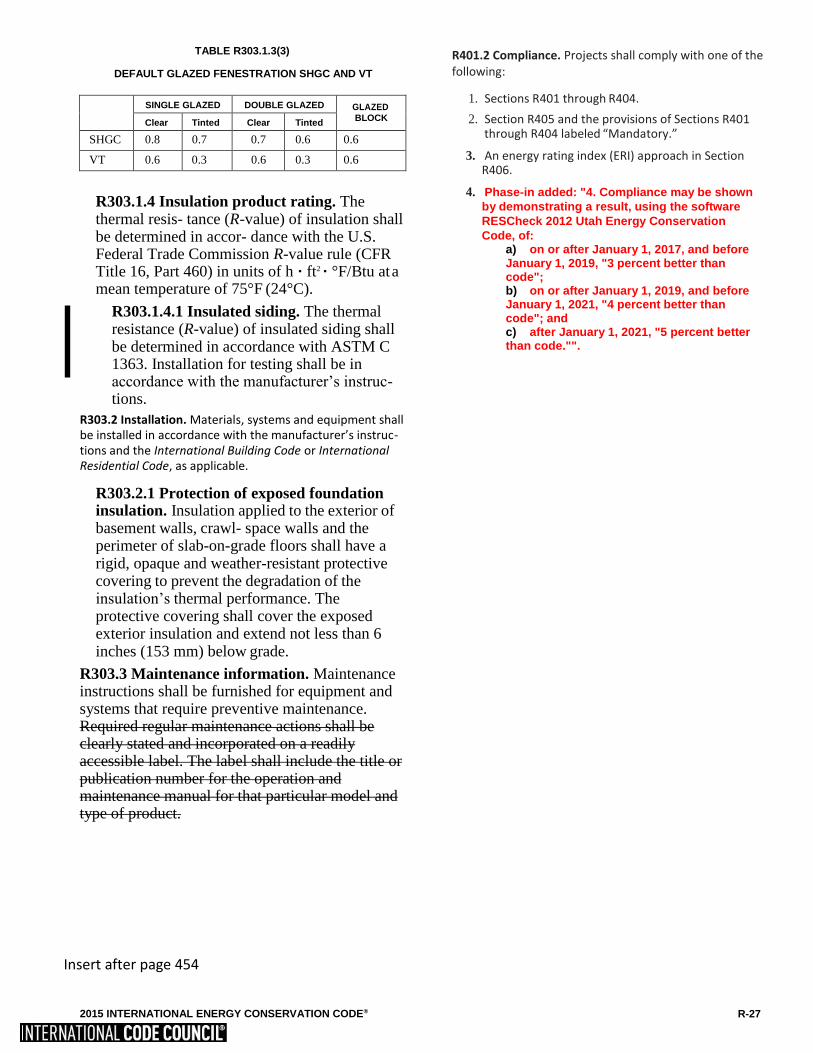
TABLE R303.1.3(3)
DEFAULT GLAZED FENESTRATION SHGC AND VT
SINGLE GLAZED DOUBLE GLAZED GLAZED
BLOCK Clear Tinted Clear Tinted
SHGC 0.8 0.7 0.7 0.6 0.6
VT 0.6 0.3 0.6 0.3 0.6
R303.1.4 Insulation product rating. The thermal resis- tance (R-value) of insulation shall be determined in accor- dance with the U.S. Federal Trade Commission R-value rule (CFR Title 16, Part 460) in units of h · ft2 · °F/Btu at a mean temperature of 75°F (24°C).
R303.1.4.1 Insulated siding. The thermal resistance (R-value) of insulated siding shall be determined in accordance with ASTM C 1363. Installation for testing shall be in accordance with the manufacturer’s instruc- tions.
R303.2 Installation. Materials, systems and equipment shall be installed in accordance with the manufacturer’s instruc- tions and the International Building Code or International Residential Code, as applicable.
R303.2.1 Protection of exposed foundation insulation. Insulation applied to the exterior of basement walls, crawl- space walls and the perimeter of slab-on-grade floors shall have a rigid, opaque and weather-resistant protective covering to prevent the degradation of the insulation’s thermal performance. The protective covering shall cover the exposed exterior insulation and extend not less than 6 inches (153 mm) below grade.
R303.3 Maintenance information. Maintenance instructions shall be furnished for equipment and systems that require preventive maintenance. Required regular maintenance actions shall be clearly stated and incorporated on a readily accessible label. The label shall include the title or publication number for the operation and maintenance manual for that particular model and type of product.
Insert after page 454
R401.2 Compliance. Projects shall comply with one of the following:
1. Sections R401 through R404.
2. Section R405 and the provisions of Sections R401 through R404 labeled “Mandatory.”
3. An energy rating index (ERI) approach in Section R406.
4. Phase-in added: "4. Compliance may be shown
by demonstrating a result, using the software
RESCheck 2012 Utah Energy Conservation
Code, of: a) on or after January 1, 2017, and before January 1, 2019, "3 percent better than code"; b) on or after January 1, 2019, and before January 1, 2021, "4 percent better than code"; and c) after January 1, 2021, "5 percent better than code."".

RESIDENTIAL ENERGY EFFICIENCY
TABLE R402.1.4
EQUIVALENT U-FACTORSa
CLIMATE ZONE
FENESTRATION U-FACTOR
SKYLIGHT U-FACTOR
CEILING U-FACTOR
FRAME
WALL U-FACTOR
MASS WALL U-FACTORb
FLOOR U-FACTOR
BASEMENT
WALL U-FACTOR
CRAWL
SPACE
WALL U-
FACTOR
1 0.50 0.75 0.035 0.084 0.197 0.064 0.360 0.477
2 0.40 0.65 0.030 0.084 0.165 0.064 0.360 0.477
3 0.35 0.55 0.030 0.060 0.098 0.047 0.091c
0.136
4 except
Marine
0.35 0.55 0.026 0.060 0.098 0.047 0.059 0.065
5 and Marine 4 0.32 0.55 0.026 0.060 0.082 0.033 0.050 0.055
6 0.32 0.55 0.026 0.045 0.060 0.033 0.050 0.055
7 and 8 0.32 0.55 0.026 0.045 0.057 0.028 0.050 0.055
a. Nonfenestration U-factors shall be obtained from measurement, calculation or an approved source. b. When more than half the insulation is on the interior, the mass wall U-factors shall be a maximum of 0.17 in
Climate Zone 1, 0.14 in Climate Zone 2, 0.12 in Climate Zone 3, 0.087 in Climate Zone 4 except Marine, 0.065 in Climate Zone 5 and Marine 4, and 0.057 in Climate Zones 6 through 8.
c. Basement wall U-factor of 0.360 in warm-humid locations as defined by Figure R301.1 and Table R301.1.
In the column entitled MASS WALL R-VALUE a new footnote j is added as follows: "j, Log walls complying with the
ICC400 and with a minimum average wall thickness of 5" or greater shall be permitted in Zones 5-8 when overall window
glazing is .31 U-factor or lower, minimum heating equipment efficiency is 90 AFUE (gas) or 84 AFUE (oil), and all other
requirements are met."
Insert after page 456
R-30 2015 INTERNATIONAL ENERGY CONSERVATION CODE®

2015 INTERNATIONAL ENERGY CONSERVATION CODE® R-33

2015 INTERNATIONAL ENERGY CONSERVATION CODE® R-33

2015 INTERNATIONAL ENERGY CONSERVATION CODE® R-33
3.5 ACH begining Jan 1 2019;
3 ACH beginning Jan 1 2021
R402.3.3 Glazed fenestration exemption. Up to 15 square feet (1.4 m2) of glazed fenestration per dwelling unit shall be permitted to be exempt from U-factor and SHGC requirements in Section R402.1.2. This exemption shall not apply to the U-factor alternative approach in Section R402.1.4 and the Total UA alternative in Section R402.1.5.
R402.3.4 Opaque door exemption. One side-hinged opaque door assembly up to 24 square feet (2.22 m2) in area is exempted from the U-factor requirement in Section R402.1.4. This exemption shall not apply to the U-factor alternative approach in Section R402.1.4 and the total UA alternative in Section R402.1.5.
R402.3.5 Sunroom fenestration. Sunrooms enclosing conditioned space shall meet the fenestration requirements of this code.
Exception: For sunrooms with thermal isolation and enclosing conditioned space in Climate Zones 2 through 8, the maximum fenestration U-factor shall be
0.45 and the maximum skylight U-factor shall be 0.70.
New fenestration separating the sunroom with thermal isolation from conditioned space shall meet the building thermal envelope requirements of this code
R402.4 Air leakage (Mandatory). The building thermal envelope shall be constructed to limit air leakage in accor- dance with the requirements of Sections R402.4.1 through R402.4.4.
R402.4.1 Building thermal envelope. The building ther-
mal envelope shall comply with Sections R402.4.1.1 OR R402.4.1.2. The sealing methods between dissimilar mate- rials shall allow for differential expansion and contraction.
R402.4.1.1 Installation. The components of the build- ing thermal envelope as listed in Table R402.4.1.1 shall be installed in accordance with the manufacturer’s instructions and the criteria listed in Table R402.4.1.1, as applicable to the method of construction. Where required by the code official, an approved third party shall inspect all components and verify
compliance.ADDED: "Where allowed by the code
official, the builder may certify compliance to components
criteria for items which may not be inspected during
regularly scheduled inspections."
Insert after page 458
R402.4.1.2 Testing. The building or dwelling unit
shall be tested and verified as having an air leakage
rate not exceeding five air changes per hour in
Climate Zones 1 and 2,
and three air changes per
hour in Climate Zones 3 through 8. Testing shall be
conducted in accordance with ASTM E 779 or ASTM
E 1827 and reported at a pressure of 0.2 inch w.g.
(50 Pascals). Where required by the code official,
testing shall be conducted by an approved third
party. A written report of the results of the test
shall be signed by the party conducting the test and
provided to the code official. Testing ADDED: "The
following parties shall be approved to conduct testing:
Parties certified by BPI or RESNET, or licensed
contractors who have completed training provided by
a Blower Door Test equipment manufacturer or
comparable training."

2015 INTERNATIONAL ENERGY CONSERVATION CODE® R-35
RESIDENTIAL ENERGY EFFICIENCY
2015 INTERNATIONAL ENERGY CONSERVATION CODE® R-35
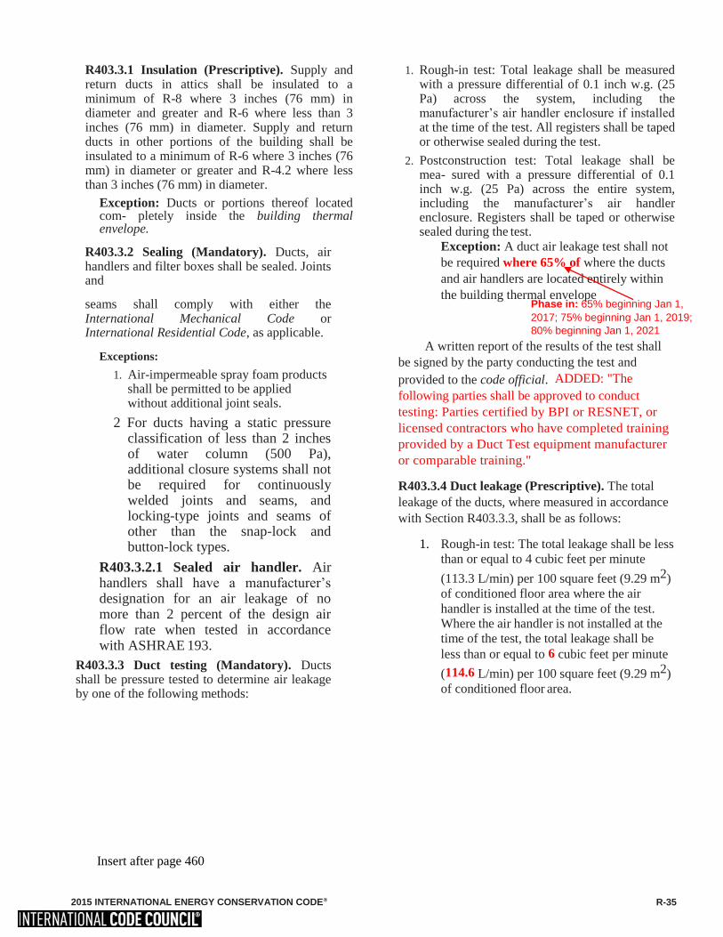
R403.3.1 Insulation (Prescriptive). Supply and return ducts in attics shall be insulated to a minimum of R-8 where 3 inches (76 mm) in diameter and greater and R-6 where less than 3 inches (76 mm) in diameter. Supply and return ducts in other portions of the building shall be insulated to a minimum of R-6 where 3 inches (76 mm) in diameter or greater and R-4.2 where less than 3 inches (76 mm) in diameter.
Exception: Ducts or portions thereof located com- pletely inside the building thermal envelope.
R403.3.2 Sealing (Mandatory). Ducts, air handlers and filter boxes shall be sealed. Joints and
seams shall comply with either the International Mechanical Code or International Residential Code, as applicable.
Exceptions:
1. Air-impermeable spray foam products shall be permitted to be applied without additional joint seals.
2 For ducts having a static pressure classification of less than 2 inches of water column (500 Pa), additional closure systems shall not be required for continuously welded joints and seams, and locking-type joints and seams of other than the snap-lock and button-lock types.
R403.3.2.1 Sealed air handler. Air handlers shall have a manufacturer’s designation for an air leakage of no more than 2 percent of the design air flow rate when tested in accordance with ASHRAE 193.
R403.3.3 Duct testing (Mandatory). Ducts shall be pressure tested to determine air leakage by one of the following methods:
1. Rough-in test: Total leakage shall be measured with a pressure differential of 0.1 inch w.g. (25 Pa) across the system, including the manufacturer’s air handler enclosure if installed at the time of the test. All registers shall be taped or otherwise sealed during the test.
2. Postconstruction test: Total leakage shall be mea- sured with a pressure differential of 0.1 inch w.g. (25 Pa) across the entire system, including the manufacturer’s air handler enclosure. Registers shall be taped or otherwise sealed during the test.
Exception: A duct air leakage test shall not
be required where 65% of where the ducts
and air handlers are located entirely within
the building thermal envelope
A written report of the results of the test shall
be signed by the party conducting the test and
provided to the code official. ADDED: "The
following parties shall be approved to conduct
testing: Parties certified by BPI or RESNET, or
licensed contractors who have completed training
provided by a Duct Test equipment manufacturer
or comparable training."
R403.3.4 Duct leakage (Prescriptive). The total
leakage of the ducts, where measured in accordance
with Section R403.3.3, shall be as follows:
1. Rough-in test: The total leakage shall be less
than or equal to 4 cubic feet per minute
(113.3 L/min) per 100 square feet (9.29 m2)
of conditioned floor area where the air
handler is installed at the time of the test.
Where the air handler is not installed at the
time of the test, the total leakage shall be
less than or equal to 6 cubic feet per minute
(114.6 L/min) per 100 square feet (9.29 m2)
of conditioned floor area.
Insert after page 460
Phase in: 65% beginning Jan 1,
2017; 75% beginning Jan 1, 2019;
80% beginning Jan 1, 2021

Phase in: 8CFM (226.5 L/min) beginning Jan 1,
2017; 7 CFM (198.2 L/min) beginning Jan 1, 2019; 6
CFM (169.9 L/min) beginning Jan 1, 2021
4
2. Postconstruction test: Total leakage shall be less than or equal to 8 cubic feet per minute( 226.5 L/
min) per 100 square feet (9.29 m2) of conditioned floor area.
R403.3.5 Building cavities (Mandatory).
Building framing cavities shall not be used as ducts or plenums.
R403.4 Mechanical system piping insulation (Manda- tory). Mechanical system piping capable of carrying fluids above 105°F (41°C) or below 55°F (13°C) shall be insulated to a minimum of R-3.
R403.4.1 Protection of piping insulation. Piping insulation exposed to weather shall be protected from damage, including that caused by sunlight, moisture, equipment maintenance and wind, and shall provide shielding from solar radiation that can cause degradation of the material. Adhesive tape shall not be permitted.
R403.5 Service hot water systems. Energy conservation measures for service hot water systems shall be in accordance with Sections R403.5.1 and R403.5.4.
R403.5.1 Heated water circulation and temperature maintenance systems (Mandatory). Heated water circulation systems shall be in accordance with Section R403.5.1.1. Heat trace temperature maintenance systems shall be in accordance with Section R403.5.1.2. Automatic Controls, temperature sensors and pumps shall be accessible. Manual controls shall be readily accessible.
R403.5.1.1 Circulation systems. Heated water circulation systems shall be provided with a circulation pump. The system return pipe shall be a dedicated return pipe or a cold water supply pipe. Gravity and thermo- syphon circulation systems shall be prohibited. Controls for circulating hot water system pumps shall start the pump based on the identification of a demand for hot water within the occupancy. The controls shall automatically turn off the pump when the water in the circulation loop is at the desired temperature and when there is no demand for hot water.
R403.5.1.2 Heat trace systems. Electric heat trace systems shall comply with IEEE 515.1 or UL 515. Controls for such systems shall
Insert after page 462
automatically adjust the energy input to the heat tracing to maintain the desired water temperature in the piping in accordance with the times when heated water is used in the occupancy.
R403.5.2 Demand recirculation systems. A water distribution system having one or more recirculation pumps that pump water from a heated water supply pipe back to the heated water source through a cold water supply pipe shall be a demand recirculation water system. Pumps shall have controls that comply with both of the following:
1. The control shall start the pump upon receiving a signal from the action of a user of a fixture or appliance, sensing the presence of a user of a fixture or sensing the flow of hot or tempered water to a fixture fitting or appliance.
2. The control shall limit the temperature of the water entering the cold water piping to 104ºF (40ºC).
R403.5.3 Hot water pipe insulation (Prescriptive). Insulation for hot water pipe with a minimum thermal resistance (R-value) of R-3 shall be applied to the following:
1. Piping 3/ inch (19.1 mm) and larger in nominal diameter.
2. serving more than one dwelling unit.
3. Piping located outside the conditioned space.
4. Piping from the water heater to a distribution manifold.
5. Piping located under a floor slab.
6. Buried in piping.
7. Supply and return piping in recirculation
systems other than demand recirculation
systems.
R403.5.4 Drain water heat recovery units. Drain water heat recovery units shall comply with CSA B55.2. Drain water heat recovery units shall be tested in accordance with CSA B55.1. Potable water-side pressure loss of drain water heat recovery units shall be less than 3 psi (20.7 kPa) for individual units connected to one or two showers. Potable water-side pressure loss of drain water heat recovery units shall be less than 2 psi (13.8 kPa) for individual units
connected to three or more showers


TABLE R406.4
MAXIMUM ENGERGY RATING INDEX
Insert after page 468
CLIMATE
ZONE
ENERGY RATING INDEX
1 52
2 52
3 65
4 54
5 69
6 68
7 53
8 53


In IRC, Section M1307.2,
The words "In Seismic Design Categories D0, D1, and D2, and in townhouses in Seismic Design
Category C", are deleted, and in Subparagraph 1, the last sentence is deleted.
Place after page 474

IRC, Section M1411.8, is deleted
Place after page 482


A new IRC, Section G2401.2, is added as follows:
"G2401.2 Meter Protection. Fuel gas services shall be in an approved location and/or provided
with structures designed to protect the fuel gas meter and surrounding piping from physical
damage, including falling, moving, or migrating ice and snow. If an added structure is used, it
must provide access for service and comply with the IBC or the IRC."
Place after 512


A new IRC, Section P2602.3, is added as follows:
"P2602.3 Individual water supply. Where a potable public water supply is not available,
individual sources of potable water supply shall be utilized, provided that the source has been
developed in accordance with Utah Code, Sections 73-3-1 and 73-3-25, as administered by the
Department of Natural Resources, Division of Water Rights. In addition, the quality of the water
shall be approved by the local health department having jurisdiction."
A new IRC, Section P2602.4, is added as follows:
"P2602.4 Sewer required. Every building in which plumbing fixtures are installed and all
premises having drainage piping shall be connected to a public sewer where the sewer is
accessible and is within 300 feet of the property line in accordance with Utah Code, Section 10-
8-38; or an approved private sewage disposal system in accordance with Utah Administrative
Code, Chapter 4, Rule R317, as administered by the Department of Environmental Quality,
Division of Water Quality."
Place after page 592


IRC, Section P2801.8,
All words in the first sentence up to the word "water" are deleted.
Place after page 603

A new IRC, Section P2902.1.1, is added as follows:
"P2902.1.1 Backflow assembly testing. The premise owner or the premise owner's designee
shall have backflow prevention assemblies operation tested in accordance with
administrative rules made by the Drinking Water Board at the time of installation, repair, and
relocation and at least on an annual basis thereafter, or more frequently as required by the
authority having jurisdiction. Testing shall be performed by a Certified Backflow Preventer
Assembly Tester. The assemblies that are subject to this paragraph are the Spill Resistant
Vacuum Breaker, the Pressure Vacuum Breaker Assembly, the Double Check Backflow
Prevention Assembly, the Double Check Detector Assembly Backflow Preventer, the
Reduced Pressure Principle Backflow Preventer, and Reduced Pressure Detector Assembly.
Third-party certification for backflow prevention assemblies will consist of any combination
of two certifications, laboratory or field. Acceptable third-party laboratory certifying
agencies are ASSE, IAPMO, and USC-FCCCHR. USC-FCCCHR currently provides the
only field testing of backflow protection assemblies. Also see www.drinkingwater.utah.gov
and rules made by the Drinking Water Board."
Place after page 606

IRC, Section P2902.1, the following subsections are added as follows:
"P2902.1.1 General Installation Criteria. Assemblies shall not be installed more than
five feet above the floor unless a permanent platform is installed. The assembly
owner, where necessary, shall provide devices or structures to facilitate testing,
repair, and maintenance, and to insure the safety of the backflow technician.
P2902.1.2 Specific Installation Criteria.
P2902.1.2.1 Reduced Pressure Principle Black flow Prevention Assembly.
The reduced pressure principle backflow prevention assembly shall be installed as follows:
a. The assembly may not be installed in a pit.
b. The relief valve of the assembly shall not be directly connected to a waste
disposal line, including a sanitary sewer, a storm drain, or a vent.
c. The assembly shall be installed in a horizontal position only, unless listed or
approved for vertical installation in accordance with Section 303.4.
d. The bottom of the assembly shall be installed a minimum of 12 inches above the
floor or ground.
e. The body of the assembly shall be a minimum of 12 inches from any wall,
ceiling, or obstacle, and shall be readily accessible for testing, repair, and maintenance.
P2902.1.2.2 Double Check Valve Backflow Prevention Assembly.
A double check valve backflow prevention assembly shall be installed as follows:
a. The assembly shall be installed in a horizontal position only, unless listed or
approved for vertical installation.
b. The bottom of the assembly shall be a minimum of 12 inches above the ground
or floor.
c. The body of the assembly shall be a minimum of 12 inches from any wall,
ceiling, or obstacle, and shall be readily accessible for testing, repair, and maintenance.
d. If installed in a pit, the assembly shall be installed with a minimum of 12 inches of
clearance between all sides of the vault, including the floor and roof or ceiling, with adequate
room for testing and maintenance.
P2902.1.2.3 Pressure Vacuum Break Assembly and Spill Resistant Pressure Vacuum
Breaker Assembly. A pressure vacuum break assembly or a spill resistant pressure vacuum
breaker assembly shall be installed as follows:
a. The assembly shall not be installed in an area that could be subject to backpressure
or back drainage conditions.
b. The assembly shall be installed a minimum of 12 inches above all downstream
piping and the highest point of use.
c. The assembly shall be a minimum of 12 inches from any wall, ceiling, or obstacle,
and shall be readily accessible for testing, repair, and maintenance.
d. The assembly shall not be installed below ground, in a vault, or
in a pit.
e. The assembly shall be installed in a vertical position."
Place after page 606

IRC, Section P2910.5, is deleted and replaced with the following:
"P2910.5 Potable water connections. When a potable water system is
connected to a nonpotable water system, the potable water system shall
be protected against backflow by a reduced pressure backflow
prevention assembly or an air gap installed in accordance with Section
2901."
Place after page 628

IRC, Section P2910.9.5, is deleted and replaced with the following:
"P2910.9.5 Makeup water.
Where an uninterrupeted nonpotable water supply is required for the intended application,
potable or reclaimed water shall be provided as a source of makeup water for the storage tank.
The makeup water supply shall be protected against backflow by means of an air gap not less
than 4 inches (102 millimeters) above the overflow or by a reduced pressure backflow prevention
assembly installed in accordance with Section 2902."
Place after 628
In IRC, Section P2911.12.4,
The following words are deleted: "and backwater valves".
Place after page 632

IRC, Section P2912.15.6,
The following words are deleted: "and backwater valves".
IRC, Section P2913.4.2,
The following words are deleted: "and backwater valves".
Place after page 634


IRC, Section P3009, is deleted and replaced with the following:
"P3009 Connected to nonpotable water from on-site water reuse systems. Nonpotable systems
utilized for subsurface irrigation for single-family residences shall comply with the requirements
of R317-401, UAC, Gray Water Systems."
Place after page 644


In IRC, Section P3103.6,
The following sentence is added at the end of the paragraph: "Vents extending through the wall
shall terminate not less than 12 inches from the wall with an elbow pointing downward."
Place after 646

In IRC, Section P3104.4,
The following sentence is added at the end of the paragraph: "Horizontal dry vents below the
flood level rim shall be permitted for floor drain and floor sink installations when installed below
grade in accordance with Chapter 30, and Sections P3104.2 and P3104.3. A wall cleanout shall
be provided in the vertical vent."
Place after page 648


IRC, Section E3901.9, the following exception is added:
"Exception: Receptacles or other outlets adjacent to the exterior walls of the garage, outlets
adjacent to an exterior wall of the garage, or outlets in a storage room with entry from the garage
may be connected to the garage branch circuit."
Place after page 696

IRC, Section E3902.16,
The following words in the first sentence are deleted: "family rooms, dining rooms, living rooms,
parlors, libraries, dens," and "sunrooms, recreation rooms, closets, hallways, and similar rooms
or areas."
Place after page 698

In Section E3902.17:
(a) following the word "Exception" the number "1." is added; and (b) at the end of the
section, the following sentences are added: "2. This section does not apply for a simple
move or an extension of a branch circuit or an outlet which does not significantly
increase the existing electrical load. This exception does not include changes involving
remodeling or additions to a residence."
Place after 698


IRC, Chapter 44, is amended by adding the following reference standard:
"Standard reference
number
Title Referenced in code
section number
USC-FCCCHR 10th Foundation for Cross-Connection Control Table P2902.3"
Edition Manual of and Hydraulic Research University of
Cross Connection Southern California Kaprielian Hall 300
Control Los Angeles CA 90089-2531
Place after page 746