Embed Size (px)
Citation preview
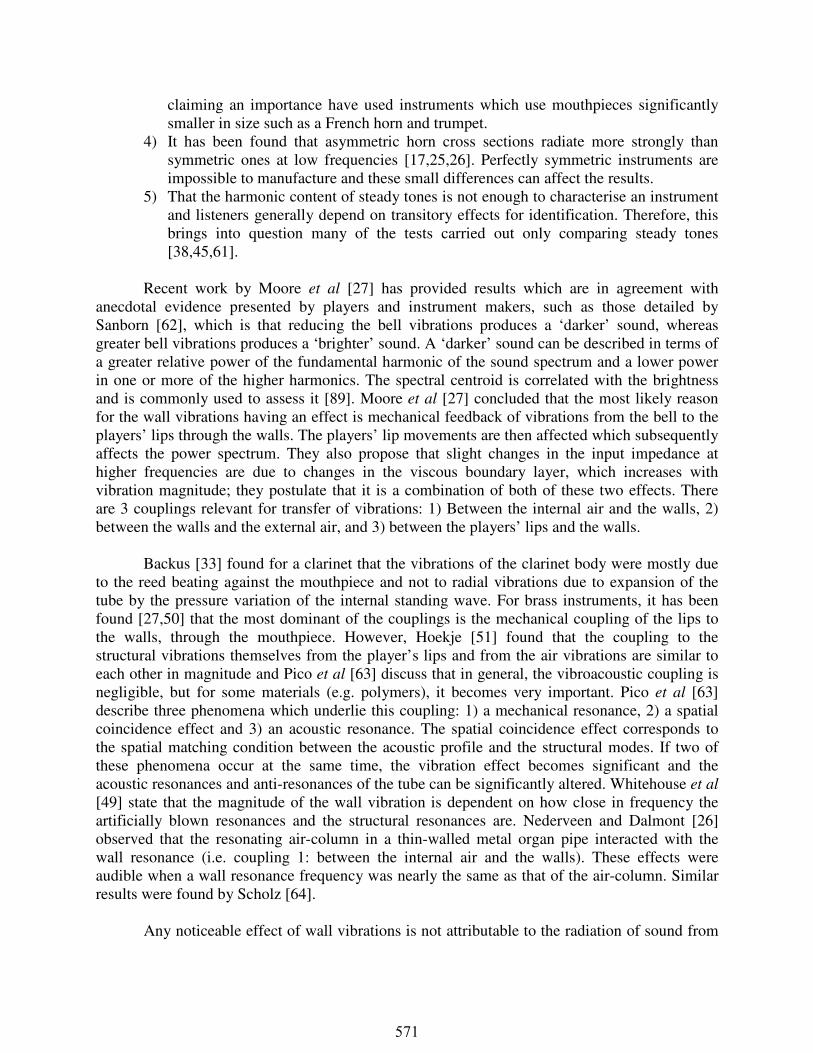
UTILISING THE DESIGN FREEDOMS OF RAPID MANUFACTURING TO
OPTIMISE STRUCTURAL AND ACOUSTICAL INTERACTIONS OF
‘BRASS’ MUSICAL INSTRUMENTS
D. J. Brackett, I. A. Ashcroft, and R. J. Hague,
Wolfson School of Mechanical and Manufacturing Engineering, Loughborough University, Leicestershire, LE11 3TU, UK
Reviewed, accepted September 10, 2008Abstract
The feasibility of the production of end use ‘brass’ musical instruments using Rapid Manufacturing (RM) is discussed with an emphasis on optimising the structural resonance through stiffening structures. The method is based upon a coupling between the air-column and structure when their resonant frequencies approach each other, which accentuates the players’ lip to wall coupling effect. The degree of wall vibration and the frequencies at which it occurs can be controlled by variation of the structure’s stiffness and the design freedoms allowed by RM enable greater control of this. Initial results of the structures and their performance are presented.
Introduction
This paper looks at the multi-disciplinary optimisation of air-column instruments accounting for wall vibrations. It includes modal, stress, mass reduction and manufacturing constraints. It outlines the principle and methodology for including the interactions between the structure and the air-column into an optimisation loop. Initial results are presented while the ongoing research is carried out. While in this case the method is defined for brass instrument application, it could also be applied to other areas such as vehicular exhaust systems.
The subject of whether the wall vibrations of an air-column musical instrument, such as a
trumpet, has an effect on the resulting sound has seen much debate over the past 100 or so years. There has been a great deal of conflicting research and there is still a lack of understanding of the mechanisms behind the wall vibration effect. Wall vibrations can be affected by many factors such as material type, wall thickness and structural support. Musicians and musical instrument manufacturers have long thought that these factors impacted on the sound of their air-column instrument, but scientists have had difficulty in finding convincing causes for an audible effect. Those that concluded that the wall vibrations have an audible effect were [1-27]. Those that concluded that they have little or no effect were [28-47]. Those that concluded that they still did not know based on their results whether the vibration of the walls was large enough to be significant were [48-50]. However, recently scientists have been able to explain some of the discrepancies in results. The reasons for this contradiction have been identified as:
1) The difficulties in constructing two instruments having exactly the same internal geometry and weight [48], especially out of different materials e.g. machining differences [51]. Moore et al [27] removed this potential for error, by damping the same geometry to lesser or greater extents to vary the wall vibration, instead of using different samples.
2) The extreme differences in results between human players of the same instrument [47]. Artificial lips such as that used by [50,52,53-59] can be used to improve repeatability.
3) The contradictory nature is inherent in the choice of instruments [27,60]. Authors claiming a lack of importance of bell vibrations have used trombones, while those
570
claiming an importance have used instruments which use mouthpieces significantly smaller in size such as a French horn and trumpet.
4) It has been found that asymmetric horn cross sections radiate more strongly than symmetric ones at low frequencies [17,25,26]. Perfectly symmetric instruments are impossible to manufacture and these small differences can affect the results.
5) That the harmonic content of steady tones is not enough to characterise an instrument and listeners generally depend on transitory effects for identification. Therefore, this brings into question many of the tests carried out only comparing steady tones [38,45,61].
Recent work by Moore et al [27] has provided results which are in agreement with
anecdotal evidence presented by players and instrument makers, such as those detailed by Sanborn [62], which is that reducing the bell vibrations produces a ‘darker’ sound, whereas greater bell vibrations produces a ‘brighter’ sound. A ‘darker’ sound can be described in terms of a greater relative power of the fundamental harmonic of the sound spectrum and a lower power in one or more of the higher harmonics. The spectral centroid is correlated with the brightness and is commonly used to assess it [89]. Moore et al [27] concluded that the most likely reason for the wall vibrations having an effect is mechanical feedback of vibrations from the bell to the players’ lips through the walls. The players’ lip movements are then affected which subsequently affects the power spectrum. They also propose that slight changes in the input impedance at higher frequencies are due to changes in the viscous boundary layer, which increases with vibration magnitude; they postulate that it is a combination of both of these two effects. There are 3 couplings relevant for transfer of vibrations: 1) Between the internal air and the walls, 2) between the walls and the external air, and 3) between the players’ lips and the walls.
Backus [33] found for a clarinet that the vibrations of the clarinet body were mostly due
to the reed beating against the mouthpiece and not to radial vibrations due to expansion of the tube by the pressure variation of the internal standing wave. For brass instruments, it has been found [27,50] that the most dominant of the couplings is the mechanical coupling of the lips to the walls, through the mouthpiece. However, Hoekje [51] found that the coupling to the structural vibrations themselves from the player’s lips and from the air vibrations are similar to each other in magnitude and Pico et al [63] discuss that in general, the vibroacoustic coupling is negligible, but for some materials (e.g. polymers), it becomes very important. Pico et al [63] describe three phenomena which underlie this coupling: 1) a mechanical resonance, 2) a spatial coincidence effect and 3) an acoustic resonance. The spatial coincidence effect corresponds to the spatial matching condition between the acoustic profile and the structural modes. If two of these phenomena occur at the same time, the vibration effect becomes significant and the acoustic resonances and anti-resonances of the tube can be significantly altered. Whitehouse et al [49] state that the magnitude of the wall vibration is dependent on how close in frequency the artificially blown resonances and the structural resonances are. Nederveen and Dalmont [26] observed that the resonating air-column in a thin-walled metal organ pipe interacted with the wall resonance (i.e. coupling 1: between the internal air and the walls). These effects were audible when a wall resonance frequency was nearly the same as that of the air-column. Similar results were found by Scholz [64].
Any noticeable effect of wall vibrations is not attributable to the radiation of sound from
571
the vibrating walls (2nd potential coupling in the above list) because these instruments are not percussion instruments. There are fundamental differences between instruments which make sound from vibrating air-columns, and those in which the sound comes from the vibrating structure. The sound produced by the vibrating bell of a trombone is about 10,000 times less powerful than the sound energy from the resonating air-column and, because a trumpet bell is smaller, the radiated sound is likely to be substantially lower [27]. Gautier and Tahani [48] also conclude that “the radiated sound power from the lateral wall is calculated for mechanical and acoustical excitations and is found to be much lower than the sound power radiated from the open end”. In summary, there are certain conditions that, if met, result in an instrument which is more or less susceptible to vibration and to audible differences in sound. Hence by varying the structural properties (e.g. stiffness), the difference between the structural and air-column resonant frequency and thus the degree of vibration can be controlled. If a ‘darker’ sound is desired, which is a result of an increase in power in the fundamental harmonic, a stiffer structure would be required, with the opposite being true for a ‘brighter’ sound. Sounds anywhere between these two extremes are theoretically obtainable by optimising the stiffness of the structure and the harmonic spectrum. Work is therefore needed on defining what the optimal stiffness profile would be and how to integrate this as an objective in an optimisation problem. Manufacturers produce brass instruments with different wall thicknesses specifically for players who want a brighter or darker sounding instrument and players can use additional masses to attach to the instrument in places to affect the sound. However, thick walls and the associated weight is often cited as a practical issue for players, especially for larger instruments such as trombones [62]. There is therefore potential for the weight reduction criteria to be included in the structural optimisation.
Rapid Manufacture
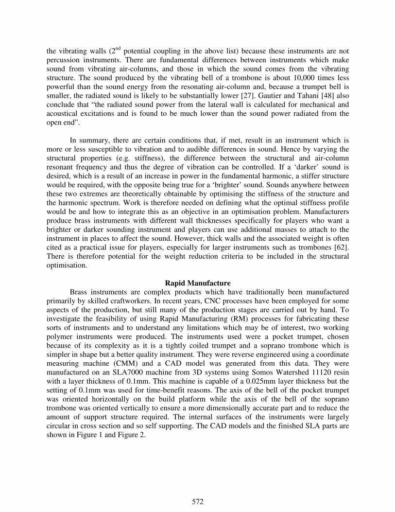
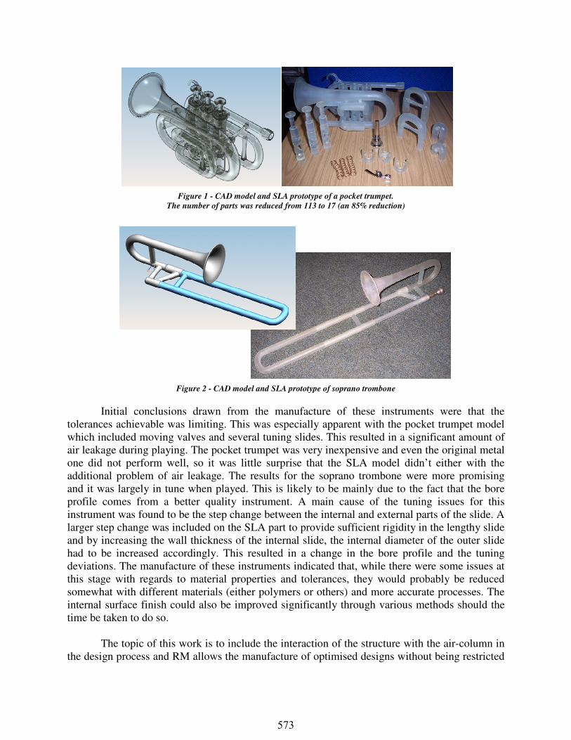
Brass instruments are complex products which have traditionally been manufactured primarily by skilled craftworkers. In recent years, CNC processes have been employed for some aspects of the production, but still many of the production stages are carried out by hand. To investigate the feasibility of using Rapid Manufacturing (RM) processes for fabricating these sorts of instruments and to understand any limitations which may be of interest, two working polymer instruments were produced. The instruments used were a pocket trumpet, chosen because of its complexity as it is a tightly coiled trumpet and a soprano trombone which is simpler in shape but a better quality instrument. They were reverse engineered using a coordinate measuring machine (CMM) and a CAD model was generated from this data. They were manufactured on an SLA7000 machine from 3D systems using Somos Watershed 11120 resin with a layer thickness of 0.1mm. This machine is capable of a 0.025mm layer thickness but the setting of 0.1mm was used for time-benefit reasons. The axis of the bell of the pocket trumpet was oriented horizontally on the build platform while the axis of the bell of the soprano trombone was oriented vertically to ensure a more dimensionally accurate part and to reduce the amount of support structure required. The internal surfaces of the instruments were largely circular in cross section and so self supporting. The CAD models and the finished SLA parts are shown in Figure 1 and Figure 2.
572
Initial conclusions drawn from the manufacture of these instruments were that the tolerances achievable was limiting. This was especially apparent with the pocket trumpet model which included moving valves and several tuning slides. This resulted in a significant amount of air leakage during playing. The pocket trumpet was very inexpensive and even the original metal one did not perform well, so it was little surprise that the SLA model didn’t either with the additional problem of air leakage. The results for the soprano trombone were more promising and it was largely in tune when played. This is likely to be mainly due to the fact that the bore profile comes from a better quality instrument. A main cause of the tuning issues for this instrument was found to be the step change between the internal and external parts of the slide. A larger step change was included on the SLA part to provide sufficient rigidity in the lengthy slide and by increasing the wall thickness of the internal slide, the internal diameter of the outer slide had to be increased accordingly. This resulted in a change in the bore profile and the tuning deviations. The manufacture of these instruments indicated that, while there were some issues at this stage with regards to material properties and tolerances, they would probably be reduced somewhat with different materials (either polymers or others) and more accurate processes. The internal surface finish could also be improved significantly through various methods should the time be taken to do so. The topic of this work is to include the interaction of the structure with the air-column in the design process and RM allows the manufacture of optimised designs without being restricted
Figure 1 - CAD model and SLA prototype of a pocket trumpet.
The number of parts was reduced from 113 to 17 (an 85% reduction)
Figure 2 - CAD model and SLA prototype of soprano trombone
573
by complexity limitations. Some of the current practical issues are going to be ignored based on the assumption that better processes and materials will be developed in the future.
Optimisation of air-column instruments
The application of computational optimisation techniques to air-column instruments has been carried out previously [66-72] but these studies focussed purely on the uncoiled bore profile of the instrument based upon its link with the input impedance and only considered the walls as rigid. Some work has been done on incorporating bends [77] as they have been found to have an audible effect, depending on their tightness [69,71,75,76]. Focus on the bore profile is understandable as it does have the greatest impact on the resulting sound, but further accuracy can be achieved by taking structural aspects into account. It is useful also to include other optimisation criterion in the process to produce coherent designs.
Other related work includes that carried out on optimising the shape and topology of loudspeaker horns [74,79]. Loudspeaker horns differ from musical horns in quite a fundamental way in that musical horns require reflections to generate standing waves, whereas loudspeaker horns require the minimum level of reflection possible (as reflections would cause the sound to distort). So instead, the goal is to optimise the transmission effectiveness of the horn to get zero reflection. This is achieved by altering the profile of the horn through the addition of mass to the inside surface to match the impedance to that of the surrounding air.
Structural optimisation based upon frequency constraints is very common as it has numerous design applications. Some of the earliest work on this was by Turner [80] who developed a finite element numerical procedure for minimising the structural mass of aircraft with specified natural frequencies. Grandhi [81] reviews this topic and identifies research by area of application, including shells. Rao and Reddy [82,83] looked at the weight minimisation of stiffened cylindrical and conical shells with natural frequency constraints using variables of shell wall thickness, sizes of stiffeners and the number of rings and stringers (longitudinal beams that connect the rings). Bratus [84] varied the thickness of cylindrical shells to obtain the minimum weight for axi- and non-axisymmetric cases. In a slightly different approach to weight minimisation, Hassan et al [85] maximised the fundamental frequency of a conical shell without increasing the total structural mass, using stiffening rings. All the literature on shell optimisation with frequency constraints seems to be basically sizing and shape optimisation. While not directly applied to shell problems, Xie and Steven [86] use the Evolutionary Structural Optimisation (ESO) method to optimise topology, subject to different frequency constraints. Material is removed after each design iteration to move the frequencies in the desired direction. Topology optimisation is considered to be able to produce globally optimal solutions. It is the coupling of the structural vibrations with the internal acoustic air vibrations into a multi-disciplinary optimisation model specific to air-column instrument design which is novel in this research.
Overview of method
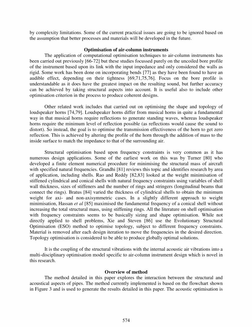
The method detailed in this paper explores the interaction between the structural and acoustical aspects of pipes. The method currently implemented is based on the flowchart shown in Figure 3 and is used to generate the results detailed in this paper. The acoustic optimisation is
574
currently loosely coupled to the structural optimisation. This method is based upon the coupling between the air-column and structure and the reason for this was explained earlier. The magnitude of the wall vibrations is greatest when the structural resonant frequency matches the air-column resonant frequency. The focus of the study is on the bell end of the instrument as this is where the amplitude of vibration is greatest. By controlling the degree of wall vibration through varying the stiffness, the resonant frequency can be controlled, enabling a desired target sound profile to be achieved; either ‘bright’, ‘dark’, or somewhere in between. Initially, the aim is to match the resonant frequencies of the air column and the structure, thereby emphasising vibrations at those frequencies. It may indeed be the case that it is desirable to avoid all structural resonant frequencies so that the degree of matching is optimised to a minimum thereby creating a darker sound.
The sound quality of a tube can be measured using the input impedance profile of the geometry. According to Moore [87], virtually everything about how a brass instrument sounds can be understood from this profile. However, the effects of wall vibrations cannot be understood based upon the input impedance because in modelling work, the walls are treated as rigid. It also
Create initial bore geometry
Assessment of acoustic input
impedance profile
Alter geometry (length and
diameter profile)
Set up geometry from acoustic
optimisation results
Calculation of input impedance of rigid
walled tube
Obtain modal
frequencies
Intended profile
achieved?
Set limits for structural
vibrational mode constraints
No
Yes
Set up structural
optimisation model
Define boundary conditions
Solve optimisation
model
Optimisation complete,
output results
Define optimisation
objective
Define optimisation
variables
Define optimisation constraints
Create solid 3D CAD model based
on results
Direct input of geometry from acoustic
optimisation results into FEA pre-processor
CAD manipulation
Geometry representation
Stiffening structures or topology optimisation
Solely wall thickness variation along length
Figure 3 - Simplified flowchart of optimisation procedure
575
does not take into account the players’ lips and style of playing which have large control over the sound. The input impedance of a real instrument is found usually not by playing the instrument but by sending a pressure impulse down the bore and measuring the pressure variations at the input. Input impedance is a complex function of frequency, defined as the quotient of sound pressure and sound flow at the interface between the player’s lips and the mouthpiece. The air contained within the instrument will resonate based on the impedance and so the impedance should be such that the resonances are at the desired frequencies. On an impedance magnitude against frequency graph, peaks that are tallest and sharpest indicate that that particular tone is easiest to initiate and sustain without wavering. The position of these peaks determines the intonation. The impedance peaks for the harmonics of each note being played also need to be in the correct place along the frequency scale. The harmonics of a note also sound when it is played and it is the combination of all of these frequencies that gives instruments such as these their rich sound. The relative strength of the harmonics with each other influences the timbre of the sound.
A wind instrument can be described as an impedance transformer between the player and their surroundings. The geometry can be simplified and split up into many small segments, cylindrical or conical in shape. By finding the transmission matrix for each of these segments the impedance of the full impedance can be found from their product. The transmission or transfer matrix, H, for a conical or cylindrical segment is denoted by: � � ���� ������ ���� (4.1)
Where each element of the matrix is calculated based on the dissipative versions from Mapes-Riodan [73] for spherical wavefronts. Once the transmission matrix has been found for each segment, the transmission matrix for the whole instrument can be found: � � ������…� (4.2) Where Hi is the transmission matrix of the ith element from the left. The input impedance, Zin of the impedance transformer is calculated from H as follows: � � ��� � ���
��� � ��� (4.3)
Where ZL is the radiation impedance seen from the end of the instrument as calculated by Caussé et al [88]. This method has been formed into an optimisation loop that uses a genetic algorithm (GA) implemented in Matlab to find the global optimum. A target input impedance profile is defined with peaks centred on desired note frequencies and with a desired magnitude The optimiser then finds the geometry that has the impedance profile that matches the target.
To get an understanding of the manufacturing limits that would be used as an
optimisation constraint a test was carried out to investigate what was the thinnest wall that could be made using the SLA7000 machine for a horn geometry. A self supporting horn was designed and the wall thickness specified at 0.3mm (close to specified machine capability limits). The resulting part was slightly thicker than this (~0.5mm) due to machine calibration issues and that the laser power was low. However, other more modern machines can produce thinner parts.
Geometry representation for Structural Optimisation
The geometry is represented in different ways for finite element analysis (FEA) and optimisation depending on the method used to achieve the optimisation objective. For instance, for wall thickness variation using 2D shell elements, the acoustically optimised bore profile is
576
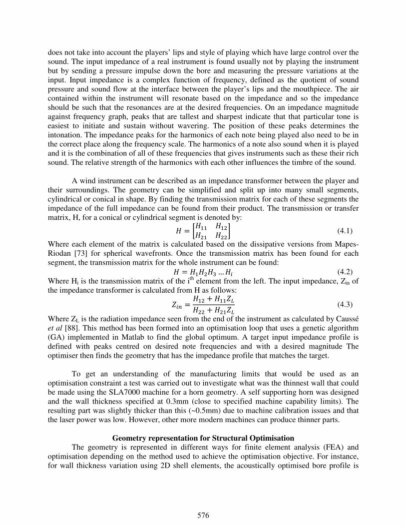
directly transferred to the pre-processor and the optimisation model set up using scripting. Figure 4 shows a simplified four variable bore profile which then is split into four wall thickness variables for structural optimisation. Boundary conditions are applied for nodes that are fixed, i.e. at the players lips and instrument support braces, and a load applied to the end. This basically forms a cantilever problem which, while is not meant to be a completely realistic representation of the problem at this stage, it allows the method to be developed. Once the correct boundary conditions are worked out it is a simple task to replace the existing ones with them. Equally, the number of variables would be increased to increase the extent of the optimisation. The material used was Somos Watershed 11120 and for this initial study the material properties were1: Elastic modulus 2765MPa, Tensile strength 47.1-53.6MPa, density 1120kg/m3, and Poisson ratio 0.452. More reliable material properties data has been obtained from experiments carried out at Loughborough University and this will be used for future studies.
Figure 4 - Load cases for a) linear static and b) normal modes, showing boundary conditions, mesh, and shell variables.
Red dots indicate specific nodes that were fixed to represent support brace positions.
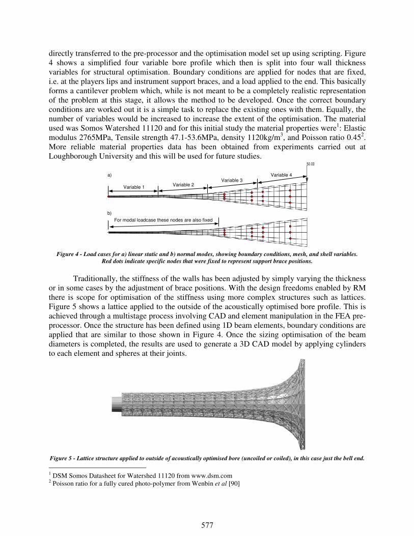
Traditionally, the stiffness of the walls has been adjusted by simply varying the thickness or in some cases by the adjustment of brace positions. With the design freedoms enabled by RM there is scope for optimisation of the stiffness using more complex structures such as lattices. Figure 5 shows a lattice applied to the outside of the acoustically optimised bore profile. This is achieved through a multistage process involving CAD and element manipulation in the FEA pre-processor. Once the structure has been defined using 1D beam elements, boundary conditions are applied that are similar to those shown in Figure 4. Once the sizing optimisation of the beam diameters is completed, the results are used to generate a 3D CAD model by applying cylinders to each element and spheres at their joints.
Figure 5 - Lattice structure applied to outside of acoustically optimised bore (uncoiled or coiled), in this case just the bell end.
1 DSM Somos Datasheet for Watershed 11120 from www.dsm.com 2 Poisson ratio for a fully cured photo-polymer from Wenbin et al [90]
Variable 1 Variable 2
Variable 3 Variable 4
For modal loadcase these nodes are also fixed
a)
b)
577
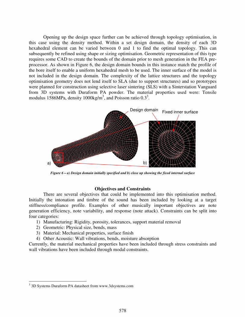
Opening up the design space further can be achieved through topology optimisation, in this case using the density method. Within a set design domain, the density of each 3D hexahedral element can be varied between 0 and 1 to find the optimal topology. This can subsequently be refined using shape or sizing optimisation. Geometric representation of this type requires some CAD to create the bounds of the domain prior to mesh generation in the FEA pre-processor. As shown in Figure 6, the design domain bounds in this instance match the profile of the bore itself to enable a uniform hexahedral mesh to be used. The inner surface of the model is not included in the design domain. The complexity of the lattice structures and the topology optimisation geometry does not lend itself to SLA (due to support structures) and so prototypes were planned for construction using selective laser sintering (SLS) with a Sinterstation Vanguard from 3D systems with Duraform PA powder. The material properties used were: Tensile modulus 1586MPa, density 1000kg/m3, and Poisson ratio 0.33.
Figure 6 – a) Design domain initially specified and b) close up showing the fixed internal surface
Objectives and Constraints
There are several objectives that could be implemented into this optimisation method. Initially the intonation and timbre of the sound has been included by looking at a target stiffness/compliance profile. Examples of other musically important objectives are note generation efficiency, note variability, and response (note attack). Constraints can be split into four categories:
1) Manufacturing: Rigidity, porosity, tolerances, support material removal 2) Geometric: Physical size, bends, mass 3) Material: Mechanical properties, surface finish 4) Other Acoustic: Wall vibrations, bends, moisture absorption
Currently, the material mechanical properties have been included through stress constraints and wall vibrations have been included through modal constraints.
3 3D Systems Duraform PA datasheet from www.3dsystems.com
Design domain Fixed inner surface
a) b)
578
Initial results for the wall thickness variation and also initial lattice sizing and optimisation results are presented here.at a later stage.
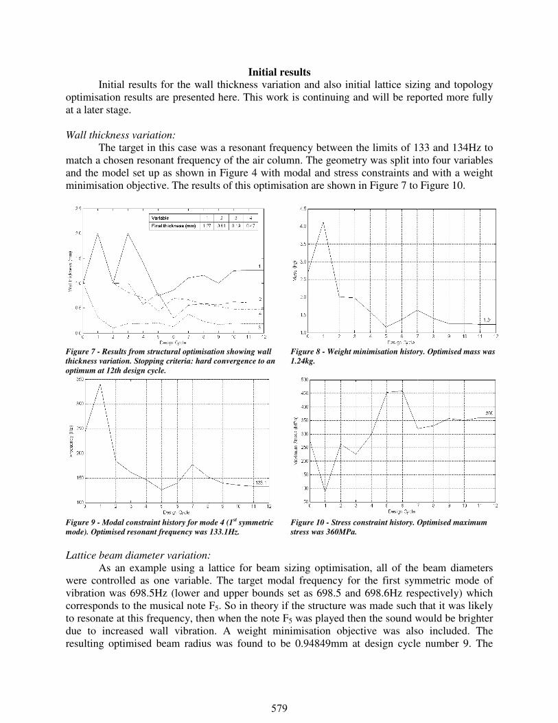
Wall thickness variation:
The target in this case was match a chosen resonant frequency of the air column.and the model set up as shown in minimisation objective. The results of this optimisation are shown in
Figure 7 - Results from structural optimisation showing wall
thickness variation. Stopping criteria: hard convergence to an
optimum at 12th design cycle.
Figure 9 - Modal constraint history for mode 4 (
mode). Optimised resonant frequency was
Lattice beam diameter variation:
As an example using a lattice for beam sizing optimisatiwere controlled as one variablevibration was 698.5Hz (lower and upper bounds set as 698.5 and 698.6Hz respectively) corresponds to the musical note Fto resonate at this frequency, then when the note Fdue to increased wall vibration. resulting optimised beam radius
Initial results
all thickness variation and also initial lattice sizing and results are presented here. This work is continuing and will be reported more fully
The target in this case was a resonant frequency between the limits of 133 and 134Hza chosen resonant frequency of the air column. The geometry was split into four variables
in Figure 4 with modal and stress constraints and withThe results of this optimisation are shown in Figure 7 to
Results from structural optimisation showing wall
s variation. Stopping criteria: hard convergence to an
Figure 8 - Weight minimisation history. Optimised mass was
1.24kg.
mode 4 (1st symmetric
mode). Optimised resonant frequency was 133.1Hz.
Figure 10 - Stress constraint history. Optimised maximum
stress was 360MPa.
:
As an example using a lattice for beam sizing optimisation, all of the beam diameters were controlled as one variable. The target modal frequency for the first symmetric
(lower and upper bounds set as 698.5 and 698.6Hz respectively) note F5. So in theory if the structure was made such that it was likely
to resonate at this frequency, then when the note F5 was played then the sound would be brighter due to increased wall vibration. A weight minimisation objective was also included.
radius was found to be 0.94849mm at design cycle number 9.
all thickness variation and also initial lattice sizing and topology This work is continuing and will be reported more fully
frequency between the limits of 133 and 134Hz to split into four variables
with modal and stress constraints and with a weight to Figure 10.
history. Optimised mass was
. Optimised maximum
on, all of the beam diameters the first symmetric mode of
(lower and upper bounds set as 698.5 and 698.6Hz respectively) which heory if the structure was made such that it was likely
was played then the sound would be brighter A weight minimisation objective was also included. The
was found to be 0.94849mm at design cycle number 9. The
579
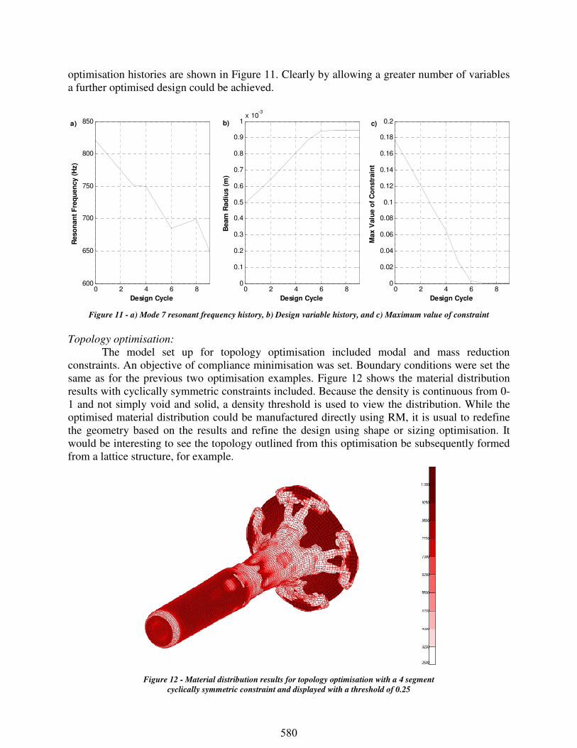
optimisation histories are shown in Figure 11. Clearly by allowing a greater number of variables a further optimised design could be achieved.
Figure 11 - a) Mode 7 resonant frequency history, b) Design variable history, and c) Maximum value of constraint
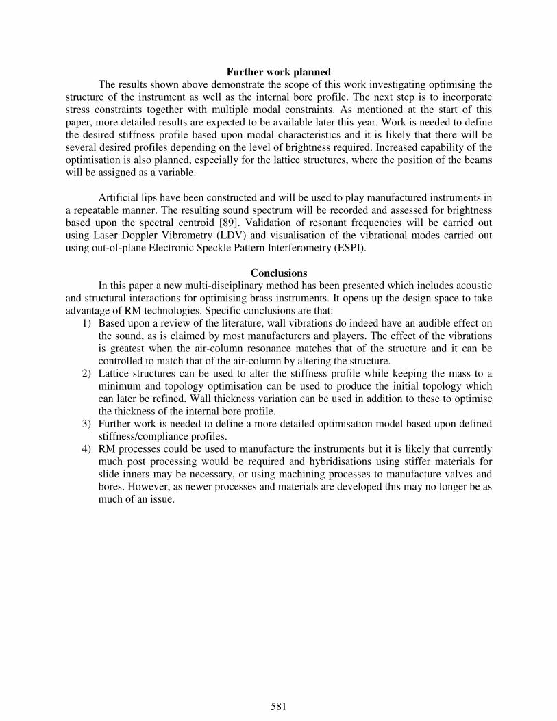
Topology optimisation:
The model set up for topology optimisation included modal and mass reduction constraints. An objective of compliance minimisation was set. Boundary conditions were set the same as for the previous two optimisation examples. Figure 12 shows the material distribution results with cyclically symmetric constraints included. Because the density is continuous from 0-1 and not simply void and solid, a density threshold is used to view the distribution. While the optimised material distribution could be manufactured directly using RM, it is usual to redefine the geometry based on the results and refine the design using shape or sizing optimisation. It would be interesting to see the topology outlined from this optimisation be subsequently formed from a lattice structure, for example.
0 2 4 6 8600
650
700
750
800
850
Design Cycle
Reso
nan
t F
req
uen
cy (
Hz)
0 2 4 6 80
0.1
0.2
0.3
0.4
0.5
0.6
0.7
0.8
0.9
1x 10
-3
Design Cycle
Beam
Rad
ius (
m)
0 2 4 6 80
0.02
0.04
0.06
0.08
0.1
0.12
0.14
0.16
0.18
0.2
Design Cycle
Max V
alu
e o
f C
on
str
ain
t
b)a) c)
Figure 12 - Material distribution results for topology optimisation with a 4 segment
cyclically symmetric constraint and displayed with a threshold of 0.25
580
Further work planned
The results shown above demonstrate the scope of this work investigating optimising the structure of the instrument as well as the internal bore profile. The next step is to incorporate stress constraints together with multiple modal constraints. As mentioned at the start of this paper, more detailed results are expected to be available later this year. Work is needed to define the desired stiffness profile based upon modal characteristics and it is likely that there will be several desired profiles depending on the level of brightness required. Increased capability of the optimisation is also planned, especially for the lattice structures, where the position of the beams will be assigned as a variable.
Artificial lips have been constructed and will be used to play manufactured instruments in a repeatable manner. The resulting sound spectrum will be recorded and assessed for brightness based upon the spectral centroid [89]. Validation of resonant frequencies will be carried out using Laser Doppler Vibrometry (LDV) and visualisation of the vibrational modes carried out using out-of-plane Electronic Speckle Pattern Interferometry (ESPI).
Conclusions
In this paper a new multi-disciplinary method has been presented which includes acoustic and structural interactions for optimising brass instruments. It opens up the design space to take advantage of RM technologies. Specific conclusions are that:
1) Based upon a review of the literature, wall vibrations do indeed have an audible effect on the sound, as is claimed by most manufacturers and players. The effect of the vibrations is greatest when the air-column resonance matches that of the structure and it can be controlled to match that of the air-column by altering the structure.
2) Lattice structures can be used to alter the stiffness profile while keeping the mass to a minimum and topology optimisation can be used to produce the initial topology which can later be refined. Wall thickness variation can be used in addition to these to optimise the thickness of the internal bore profile.
3) Further work is needed to define a more detailed optimisation model based upon defined stiffness/compliance profiles.
4) RM processes could be used to manufacture the instruments but it is likely that currently much post processing would be required and hybridisations using stiffer materials for slide inners may be necessary, or using machining processes to manufacture valves and bores. However, as newer processes and materials are developed this may no longer be as much of an issue.
581
References [1] Williams, C. F. A., 1903, The Story of the Organ, New York:
Charles Scribner & Sons, 1903 [2] Miller, D. C., 1909, The influence of the material of wind-
instruments on the tone quality, Science, Vol. 29, no. 735, pp.161-171, Jan 1909
[3] Richardson, E. G., 1929, The acoustics of orchestral instruments and of the organ, Richardson Press, 1929
[4] Lottermoser, W., 1937, Der Einfluß des Materials von Orgel-Metallpfeifen auf ihre Tongebung, Akustische Zeitschrift (Acoustic Journal), Vol. 2, pp.129–134, May 1937
[5] Lottermoser, W., 1938, Der Einfluß des Materials von Orgel-Metallpfeifen auf ihre Tongebung, Akustische Zeitschrift (Acoustic Journal), Vol. 3, pp.63-64, 1938
[6] Barnes, W. H., 1948, The Contemporary American Organ, J. Fischer and Brothers, New York, 1948
[7] Jeans, J., 1953, Science and Music, Courier Dover Publications, 1953
[8] Rendall, F. G., 1957, The Clarinet, Ernest Benn, London, 1957 [9] Baines, A., 1962, Woodwind instruments and their history, Faber,
London, 1962 [10] Lottermoser, W., and Meyer, J., 1962, Über den Einfluß des
Materials auf die klanglichen Eigenschaften von Orgelpfeifen, Metall, Vol. 16, pp.108-111, 1962
[11] Lottermoser, W., and Meyer, J., 1964, Die Verwendung von Kunststoffen bei Orgelpfeifen. Zeitschrift für Instrumentenbau (Journal of Instrument Making) Vol. 18, pp.195–199, 1964
[12] Taylor, C. A., 1965, The physics of musical sounds, The English Universities Press Ltd., London, 1965
[13] Wogram, K., 1977, Das Musikinstrument, pp.1193-1194, Sept 1977
[14] Wogram, K., 1979, Paper presented at the International Horn Workshop, Los Angeles, 1979 (from Whitehouse 2003)
[15] Smith, R. A., and Mercer D. M. A., 1979, Recent work on musical acoustics, Reports on Progress in Physics, Vol. 42, pp.1085-1129
[16] Pyle, R. W., 1981, The effect of surface coatings upon brass-instrument tone quality, The Journal of the Acoustical Society of America, Vol. 69, Issue S1, pp.S37, Apr 1981
[17] Watkinson, P. S., and Bowsher, J. M., 1982, Vibration characteristics of brass instrument bells, Journal of Sound and Vibration, Vol. 85, Issue 1, pp.1-17, 1982
[18] Lawson, B., and Lawson, W., 1985, Acoustical characteristics of annealed French horn bell flares, The Journal of the Acoustical Society of America, Vol. 77, Issue 5, pp.1913-1916, May 1985
[19] Morral, F. R., 1986, Metals and alloys in musical instruments, CIM Bulletin, Vol. 79, Issue 889, pp.86-88, 1986
[20] Gibiat, V., Bouche-Pillon, M., Perrot S., Vandenbogaerde, T., Roumaire, J., 1997, Influence des résonances mécaniques sur l’émission acoustique d'un instrument à vent simplifié, Proceedings of the Fourth Congress on Acoustics, Marseille, France, pp.585–588, 1997
[21] Runnemalm, A., 1997, Effects of material choice and tooling methods on structural modes of open organ pipes, Proceedings of the Institute of Acoustics, ISMA’97, 19, (5 (2)), pp.303-308, 1997
[22] Mainstone, J., 1998, From: The Cambridge companion to the organ by Thistlethwaite, N., and Webber, G., Cambridge University Press, 1998
[23] Cocchi, A., and Tronchin, L., 1998, Material and obsolescence on flute quality, Proceedings of the Acoustical Society of America, Vol. 103, pp.763-764, 1998
[24] Runnemalm, A., Zipser, L., and Frankc, H., 1999, Structural vibration modes of a blown open organ pipe, Acta Acustica united with Acustica, Vol. 85, No. 6, pp.877-882, Nov 1999
[25] Hoekje, P. L., and Morrison, A., 1999, Finite-element analysis of vibrating trombone bell, The Journal of the Acoustical Society of America, Vol. 105, Issue 2, pp.1126, Feb 1999
[26] Nederveen, C. J., and Dalmont, J.-P., 2004, Pitch and level changes in organ pipes due to wall resonances, Journal of Sound and Vibration, Vol. 271, pp.227-239, 2004
[27] Moore, T. R., Shirley, E. T., Codrey I. E. W., and Daniels, A. E., 2005, The effects of bell vibrations on the sound of the modern trumpet, Acta Acustica United With Acustica, Vol. 91, pp.578-589, 2005
[28] Blaikley, D. J., 1919, Metronome, Vol. 35, No. 1, pp.41-56, 1919 [29] Glatter-Götz, E. von, 1935, Der Einfluß des Wandmaterials von
Orgelpfeifen auf Klangfarbe und Lautstärke, Zeitschrift für Instrumentenbau (Journal of Instrument Making), Vol. 55, pp.96-99, 1935
[30] Boner, C. P., and Newman. R. B., 1940, The effect of wall materials on the steady-state acoustic spectrum of flue pipes, The Journal of the Acoustical Society of America, Vol. 12, Issue 1, pp.83-89, Jul 1940
[31] Knauss, H. P., and Yeager, W. J., 1941, Vibrations of the walls of a cornet, The Journal of the Acoustical Society of America, Vol. 13, Issue 2, pp.160-162, Oct 1941
[32] Parker, S. E., 1947, Analyses of the tones of wooden and metal clarinets, The Journal of the Acoustical Society of America, Vol. 19, Issue 3, pp.415-419, May 1947
[33] Backus, J., 1964, Effect of wall material on the steady-state tone quality of woodwind instruments, The Journal of the Acoustical Society of America, Vol. 36, No. 10, pp.1881-1887, October 1964
[34] Backus, J., 1965, Wall vibrations in organ pipes and their effect on tone, The Journal of the Acoustical Society of America, Vol. 38, Issue 5, pp.912, Nov 1965
[35] Backus, J., and Hindley, T. C., 1966, The Journal of the Acoustical Society of America, Wall vibrations in flue organ pipes and their effect on tone, Vol. 39, Issue 5A, pp.936-945
[36] Benade, A. H., 1967, Absorption cross section of a pipe organ due to resonant vibration of the pipe walls, The Journal of the Acoustical Society of America, Vol. 42, Issue 1, pp.210-223, Jul 1967
[37] Backus, J., 1969, The acoustical foundations of music, New York, Norton, 1969
[38] Coltman, J. W., 1971, Effect of material on flute tone quality, The Journal of the Acoustical Society of America, Vol. 49, Issue 2B, pp.520-523, Feb 1971
[39] Smith, R., 1986, The effect of material in brass instruments: a review, Proceedings of The Institute of Acoustics, Vol. 8, Issue 1, 1986
[40] Heokje, P. L., Payne, C. A., and Kjar, D. N., 1993, Brass instrument bell vibrations and coupling to air modes, The Journal of the Acoustical Society of America, Vol. 94, Issue 3, pp.1806, Sept 1993
[41] Zipser, L., and Franke, H., 1996, Vibrations of thin-walled tubes and organ flue pipes, Proceedings of SPIE Vol. 2868, Second International Conference on Vibration Measurements by Laser Techniques: Advances and Applications, Enrico P. Tomasini, Editor, Aug 1996, pp.255-262
[42] Morrison, A., and Hoekje, P. L., 1997, Internal sound field of vibrating trombone bell, The Journal of the Acoustical Society of America, Vol. 101, Issue 5, pp.3056, May 1997
[43] Angster, J., Paal, G., Garen, W., and Miklos, A., 1998, The effect of wall vibrations on the timbre of organ pipes, Proceedings of the 16th International Congress on Acoustics, Seattle, WA, 1998, pp.753-754
[44] Fletcher, N. H, and Rossing, T. D., 1998, The physics of musical instruments, Springer, 2nd Edition, 1998, Chapter 22.2: Materials for wind instruments
[45] Kob, M., 2000, Influence of wall vibrations on the transient sound of flue organ pipes, Acta Acustica united with Acustica, Vol. 86, No. 4, pp.642-648, Jul 2000
[46] Kob, M., 2001, Can wall vibrations alter the sound of a flue organ pipe, 17th International Congress on Acoustics (ICA), Rome 2001, Proceedings CD-ROM, Vol. 4
[47] Widholm, G., Bertsch, M., Kausel, W., and Linortner, R., 2001, Proceedings of International Symposium on Musical Acoustics
582
2001 (ISMA’2001), Perugia: Musical and Architectural Acoustics Lab. Venezia, pp.277-280, 2001
[48] Gautier, F., and Tahani, N., 1998, Vibroacoustic behaviour of a simplified musical wind instrument, Journal of Sound and Vibration, Vol. 213, Issue 1, pp.107-125, 1998
[49] Whitehouse, J.W., Sharp, D.B., and Harrop, N.D., 2002, An investigation into wall vibrations induced in wind instruments constructed from different metals, Proceedings of the International Symposium on Musical Acoustics, Mexico City, Mexico, Dec 2002
[50] Whitehouse, J.W., 2003, A study of the wall vibrations excited during the playing of lip-reed instruments (PhD Thesis), Oct 2003
[51] Hoekje, P. L., 2003, SEA applications to wind instruments, The Journal of the Acoustical Society of America, Vol. 113, Issue 4, pp.2315, Apr 2003
[52] Gilbert, J., Ponthus, S., and Petiot, J., 1998, Artificial buzzing lips and brass instruments: experimental results, The Journal of the Acoustical Society of America 104 (3): 1627-1632, Sept 1998
[53] Petiot, J. F., Teissier, F., Gilbert, J., and Campbell, M., 2003, Comparative analysis of brass wind instruments with an artificial mouth: First results, Acta Acustica United With Acustica, Vol. 89, pp.974-979, 2003
[54] Cullen, J. S., Gilbert, J., and Cambell, M., 2000, Brass instruments: Linear stability analysis and experiments with an artificial mouth, Acustica - Acta Acustica, Vol. 86, pp.704-724, 2000
[55] Vergez, C., and Rodet, X., 1997a, Model of the trumpet functioning: Real time simulation and experiments with an artificial mouth, ISMA97, Edinburgh, UK, Aug 1997
[56] Vergez, C., and Rodet, X., 1997b, Comparison of real trumpet playing, latex model of lips and computer model, Proceedings of the ICMC97, Thessalonique, Sept 1997
[57] Bromage, S., 2007, Visualisation of the lip motion of brass instrument players and investigations of an artificial mouth as a tool for comparative studies of instruments, PhD Thesis, University of Edinburgh, 2007
[58] Richards, O., 2003, Investigation of the lip reed using computation modelling and experimental studies with an artificial mouth, PhD Thesis, University of Edinburgh, 2003
[59] Wolfe, J., Tarnopolsky, A., Z., Fletcher, N., H., Hollenberg, L., C., L., and Smith, J., 2003, Some effects of the player’s vocal tract and tongue on wind instrument sound, Proceedings of the Stockholm Music Acoustics Conference (SMAC’03), Stockholm, Sweden, pp.307-310, Aug 2003
[60] Smith, R. A., 1978, Recent developments in trumpet design, International Trumpet Guild, Vol. 3, Oct 1978
[61] Kob, M., and Scholz, M., 1999, Simulation and measurement of wall vibrations of a flue organ pipe, The Journal of the Acoustical Society of America, Vol. 105, Issue 2, pp.1126-1127, Feb 1999
[62] Sanborn, C., 1997, Confessions of a brass repair man: an interview with Ron Partch, International Trumpet Guild Journal, Sept 1997
[63] Picó, R., Gautier, F., and Redondo, J., 2007, Acoustic input impedance of a vibrating cylindrical tube, Journal of Sound and Vibration, Vol. 301, pp.649-664, 2007
[64] Scholz, M., 2006, Sound generation in metal flue organ pipes: on the influence of asymmetric flue exit geometry and vibrations of the upper labium with particular emphasis on the early response, Vol. 2554, PhD Thesis, Chalmers University of Technology, 2006
[65] Pyle, R. W., 1998, The effect of wall materials on the timbre of brass instruments, The Journal of the Acoustical Society of America, Vol. 103, Issue 5, pp.2834, May 1998
[66] Kausel, W., 1999, Computer optimization of brass wind instruments, Diderot Forum on Mathematics and Music, 1999
[67] Kausel, W., and Anglmayer, P., 1999, A computer program for brass instrument optimization Part 2: Applications, practical examples, The Journal of the Acoustical Society of America 105 (2): 1003, 1999
[68] Noreland, D., (2002), A numerical method for acoustic waves in horns, Acta Acustica United With Acustica, 88, 576-586, 2002
[69] Noreland, D., (2003a), Numerical techniques for acoustic modelling and design of brass wind instruments, Comprehensive Summaries of Uppsala Dissertations from the Faculty of Science and Technology, 862, Acta Universitatis Upsaliensis, Uppsala 2003
[70] Noreland, D., (2003b), A gradient based optimisation algorithm for the design of brass-wind instruments, Technical Report 2003-033, Uppsala Universitet, May 2003
[71] Braden, A. C. P., (2005), Optimisation techniques for solving design problems in modern trombones, Forum Acusticum 2005, Budapest, 557-562
[72] Poirson, E., Dépincé, P., and Petiot, J-F., (2007), User-centered design by genetic algorithms: Applications to brass musical instrument optimization, Engineering Applications of Artificial Intelligence, 20 (4): 511-518, Jun 2007
[73] Mapes-Riordan, D., (1993), Horn Modeling with Conical and Cylindrical Transmission-Line Elements, Journal of Audio Engineering Society, 41 (6): 471-484, Jun 1993
[74] Bängtsson, E., Noreland, D., and Berggren, M., (2003), Shape optimization of an acoustic horn, Computer Methods in Applied Mechanics and Engineering, 192 (11-12): pp.1533-1571, Mar 2003
[75] Benade, A. H., (1976), Fundamentals of musical acoustics, Oxford University Press, 1976, ISBN: 0-401-83473-5
[76] Nederveen, C. J., (1998), Influence of a toroidal bend on wind instrument tuning, The Journal of the Acoustical Society of America, 104 (3) Part 1: 1616-1626, 1998
[77] Braden, A. C. P., (2006), Input Impedance of Bent Waveguides, Proceedings of the Institute of Acoustics, 28, Part 1, 2006
[78] Knowles, J. D., and Corne, D. W., 2000, M-PAES: A memetic algorithm for multiobjective optimization, Evolutionary Computation, 2000. Proceedings of the 2000 Congress on, Vol. 1, pp.325-332, 2000
[79] Wadbro, E., and Berggren. M., (2006), Topology optimization of an acoustic horn, Computer Methods in Applied Mechanics and Engineering, 196, 420-436, 2006
[80] Turner, J. M., 1967, Design of minimum mass structures with specified natural frequencies, AIAA Journal, Vol. 5, No. 3, pp.406-412, 1967
[81] Grandhi, R., 1993, Structural optimization with frequency constraints, AIAA Journal, Vol. 31, No. 12, pp.2296-2303, Dec 1993
[82] Rao, S. S., and Reddy, E. S., 1980, Optimum design of stiffened cylindrical shells with natural frequency constraints, Computers and Structures, Vol. 12, pp.211-219, 1980
[83] Rao, S. S., and Reddy, E. S., 1981, Optimum design of stiffened conical shells with natural frequency constraints, Computers and Structures, Vol. 14, No. 1-2, pp.103-110, 1981
[84] Bratus, A. S., 1985, Design of circular cylindrical shells of minimum weight with fixed natural oscillation frequencies, PMM U.S.S.R., Vol. 47, No. 5, pp.650-657, 1983
[85] Hassan, A. I., Maalawi, K. Y., and Negm, H. M., 2006, Frequency optimization of conical shells under mass equality constraint, Journal of Applied Sciences Research, Vol. 2, No. 11, pp.821-829, 2006
[86] Xie, Y. M., and Steven, G. P., 1996, Evolutionary Structural Optimization for dynamic problems, Computers and Structures, Vol. 58, No. 6, pp.1067-1073, 1996
[87] Moore, T. R., 2002, What is impedance and why do we care?, International Trumpet Guild Journal 27 (1): 70-71, Oct 2002
[88] Caussé, R., Kergomard, J., and Lurton, X., (1984), Input impedance of brass musical instruments – comparison between experiment and numerical models, The Journal of the Acoustical Society of America, 75 (1): 241-254, 1984
[89] Poirson, E., Petiot, J.-F, and Gilbert, J., 2005, Study of the brightness of trumpet tones, Journal of the Acoustical Society of America, Vol. 118, No. 4, Oct 2005
[90] Wenbin, H., Tsui, L. Y., and Haiqing, G., 2005, A study of the staircase effect induced by material shrinkage in rapid prototyping, Rapid Prototyping Journal, Vol. 11, Issue 2, pp.82-89, 2005
583


![Information and Software Technologygorschek.com/.../12/Utilising-CI...testing-of-NFRs.pdf · Frequent integration and automation testing [1] in a rapid iteration to enhance software](https://img.pdfslide.net/doc/110x75/5fc090e1840441746d51130a/information-and-software-frequent-integration-and-automation-testing-1-in-a-rapid.jpg)