Embed Size (px)
Citation preview
DOEMU32267 -- 5669 (DE97002299)
Utility Advanced Turbine Systems Program (ATS) Technical Readiness Testing and Pre-Commercial
Demonstration
Annual Report October 30, 1995 - September 30, 1996
Work Performed Under Contract No.: DE-FC21-95MC32267
For U.S. Department of Energy
Office of Fossil Energy Federal Energy Technology Center
Morgantown Site P.O. Box 880
Morgantown, West Virginia 26507-0880
By Westinghouse Electric Corporation
Emerging Technologies Power Generation Business Unit
4400 Alafaya Trail Orlando, Florida 32826-2399
c
Disclaimer
This report was prepared as an account of work sponsored by an agency of the United States Government. Neither the United States Government nor any agency thereof, nor any of their employees, makes any warranty, express or implied, or assumes any legal liability or responsibility for the accuracy, completeness, or use- fulness of any information, apparatus, product, or process disclosed, or represents that its use would not infringe privately owned rights Reference herein to any specific commercial product, process, or service by trade name, trademark, manufacturer, or otherwise does not necessarily constitute or imply its endorsement, recommendation, or favoring by the United States Government or any agency thereof. The views and opinions of authors expressed herein do not necessarily state or reflect those of the United States Government or any agency thereof.
P

DISCLAIMER
Portions of this document may be illegible electronic image products. Images are produced from the best available original document.
CONTENTS
.. Section Page
. 1.0
2.0
3.0
8.0
9.1
9.2
9.3
9.4
9.5
9.6
9.7
9.8
9.9
9.10
9.1 1
9.12
9.13
9.14
9.15
9.16
11.0
NEPA INFORMATION ..................................................................... 1
ATS ENGINE DESIGN ...................................................................... 1
SPECIFICATION & DESIGN OF POWER PLANT EQUIPMENT.. 7
INTEGRATED PROGRAM PLAN ................................................... 7
CLOSED LOOP COOLING ............................................................... 8
THIN WALL CASTING DEVELOPMENT ....................................... 9
ROTOR AIR SEALING DEVELOPMENT ........................................ 12
COMPRESSOR AERODYNAMIC DEVELOPMENT ...................... 14
TURBINE AERODYNAMIC DEVELOPMENT ................................ 15
PHASE 3 ADVANCED AIR SEALING DEVELOPMENT ............... 16
‘k$CTIVE TIP CLEARANCE CONTROL ............................................ 18
COMBUSTION SYSTEM DEVELOPMENT ..................................... 20
CERAMIC RING SEGMENT .............................................................. 21
ADVANCED TBC DEVELOPMENT .................................................. 24
STEAM COOLING EFFECTS ............................................................. 29
DIRECTIONALLY SOLIDIFIED BLADE DEVELOPMENT ........... 31
SINGLE CRYSTAL BLADE DEVELOPMENT PROGRAM ............. 32
ADVANCED VANE ALLOY DEVELOPMENT ................................ 33
BLADE AND VANE LIFE PREDICTION .......................................... 33
\
NICKEL-BASED ALLOY ROTOR .................................................... 35
PROGRAM MANAGEMENT ............................................................ 36
1.0 NEPA INFORMATION
National Environmental Policy Act Information (NEPA) information for ATS Phase 3 component and systems testing was submitted to METC for preparation of the NEPA Report during the first quarter of FY 96.
Additional Phase 3 combustion testing emissions data was requested and submitted for clarification. NEPA report review by METC has resulted in an additional request for information regarding the use of cooling water during the Phase 3 combustion tests.
Documents explaining the most frequently asked question about NEPA submittals on DOE projects was received from METC during the second quarter.
2.0 ATS ENGINE DESIGN
The ATS Engine design concept is based on a mix of well proven Westinghouse design features with innovative, performance enhancing advanced technology. The 60% combined cycle efficiency will be met while maintaining structural integrity and engine reliability. A risk analysis of ATS engine design has identified where the highest probability and consequences of risk exist. Mitigation plans to counter any identified risk have been initiated.
During~FY’96 the ATS engine design has proceeded on schedule through the conceptual design &ase into detailed design.
Aerodynamic and mechanical design of the 30: 1 ATS compressor was completed during FY96. The compressor design has been released for manufacturing. Manufacturing of the compressor components are on schedule for use in ATS Compressor test rig.
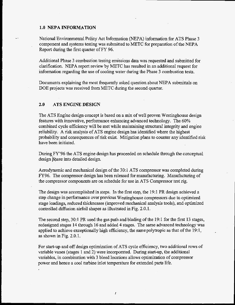
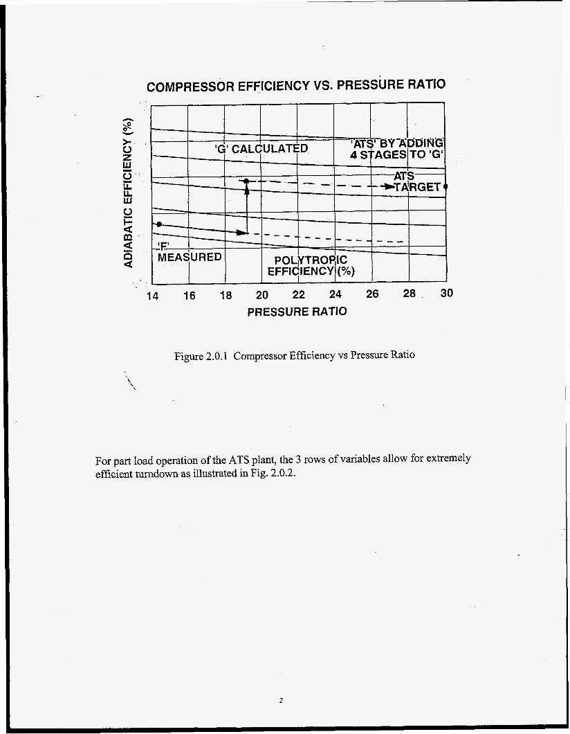
The design was accomplished in steps. In the fmt step, the 19:l PR design achieved a step change in performance over previous Westinghouse compressors due to optimized stage loadings, reduced thicknesses (improved mechanical analysis tools), and optimized controlled diffusion airfoil shapes as illustrated in Fig. 2.0.1.
The second step, 30: 1 PR used the gas path and blading of the 19:l for the first 13 stages, redesigned stages 14 through 16 and added 4 stages. The same advanced technology was applied to achieve exceptionally high efficiency, the same polytropic as that of the 19: 1, as shown in Fig. 2.0.1.
For start-up and off design optimization of ATS cycle efficiency, two additional rows of variable vanes (stages 1 and 2) were incorporated. During start-up, the additional variables, in combination with 3 bleed locations allows optimization of compressor power and hence a COO^ turbine inlet temperature for extended parts life.
I
_ - COMPRESSOR EFFICIENCY vs. PRESSURE RATIO I
-
'ATS' BY-AD'DIflG - 'G' CALCULATED 4 STAGESIT0 'GI I I
14 16 18 20 22 24 26 28 30
PRESSURE RATIO
Figure 2.0.1 Compressor Efficiency vs Pressure Ratio
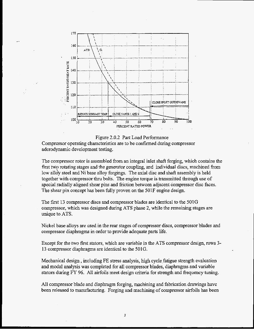
For part load operation of the ATS plant, the 3 rows of variables allow for extremely efficient turndown as illustrated in Fig. 2.0.2.
. .. PLPCEM W E D POWER
Figure 2.0.2 Part Load Performance Compressor operating characteristics are to be confirmed during compressor aderodynamic development testing.
The compressor rotor is assembled fiom an integral inlet shaft forging, which contains the first two rotating stages and the generator coupling, and individual discs, machined fiom low all& steel and Ni base alloy forgings. The axial disc and shaft assembly is held together with compressor thru bolts. The engine torque is transmitted through use of special radially aligned shear pins and fiction between adjacent compressor disc faces. The shear pin concept has been fully proven on the 501F engine design.
The first 13 compressor discs and compressor blades are identical to the 501G compressor, which was designed during ATS phase 2, while the remaining stages are unique to ATS.
Nickel base alloys are used in the rear stages of compressor discs, compressor blades and compressor diaphragms in order to provide adequate parts life.
Except for the two first stators, which are variable in the ATS compressor design, rows 3- 13 compressor diaphragms are identical to the 501G.
Mechanical design , including FE stress analysis, high cycle,fatigue strength evaluation and modal analysis was completed for all compressor blades, diaphragms and variable stators during FY 96. All airfoils meet design criteria for strength and frequency tuning.
All compressor blade and diaphragm forging, machining and fabrication drawings have been released to manufacturing. Forging and machining of compressor airfoils has been
3
initiated during FY 96. Compressor disc forgings are on order and some forgings have been delivered in FY96. All components remain on schedule for build of ATS Compressor Test Rig in 1997.
Steel blocks have been ordered in preparation for compressor blade static frequency verification test in first quarter of 1997. Rotating compressor blade frequency verification will be carried out during ATS compressor rig test in third quarter of 1997.
ATS inlet cylinder, thrust bearing and journal bearing are identical to 501G. The inlet casing is in the process of being cast.
The compressor cylinder, although having common flow path and overall length to the 50 1 G, has been modified to accommodate two stages of variable stators and related actuating mechanisms.
From stage 7 and rearwards, the compressor flow path is formed by intermediate cylinders, known as compressor blade rings. These static structures have been designed and drawings completed in FY96.
The compressor rotor is connected to the four stage turbine through an intermediate spool piece, torque tube. The rotor design will use clutches for transmittal of turbine torque. The axially stacked, four stage turbine is held together with turbine thru bolts.
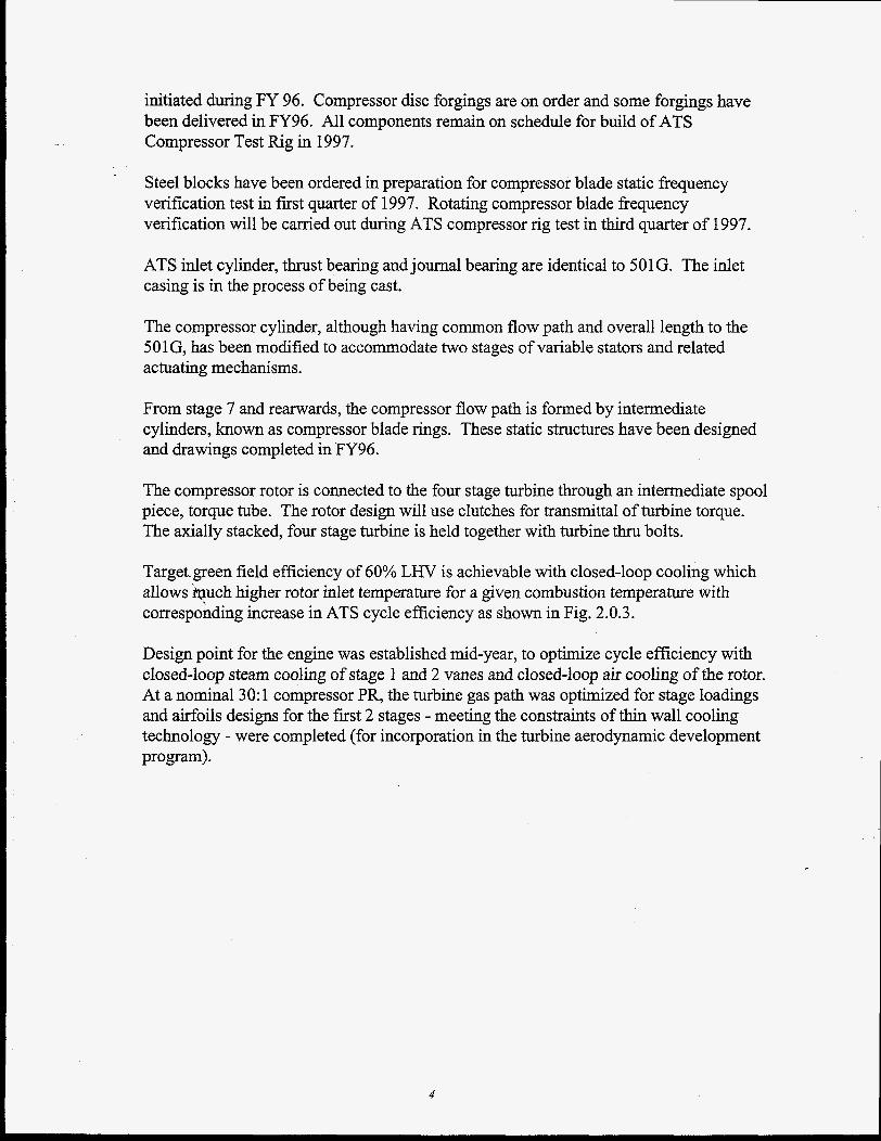
Target.green field efficiency of 60% LHV is achievable with closed-loop cooling which allows ‘buch higher rotor inlet temperature for a given combustion temperature with corresponding increase in ATS cycle efficiency as shown in Fig. 2.0.3.
Design point for the engine was established mid-year, to optimize cycle efficiency with closed-loop steam cooling of stage 1 and 2 vanes and closed-loop air cooling of the rotor. At a nominal 30: 1 compressor PR, the turbine gas path was optimized for stage loadings and airfoils designs for the first 2 stages - meeting the constraints of thin wall cooling technology - were completed (for incorporation in the turbine aerodynamic development program).
4
60
s n
W
>I. 0 z W 0 LL LL. W w A 0 ). 0 P w 2 m E 0 0
-
ROTOR INLET TEMPERATURE (TIT)
Figure 2.0.3 Efficiency Vs Rotor Inlet Temperature '\
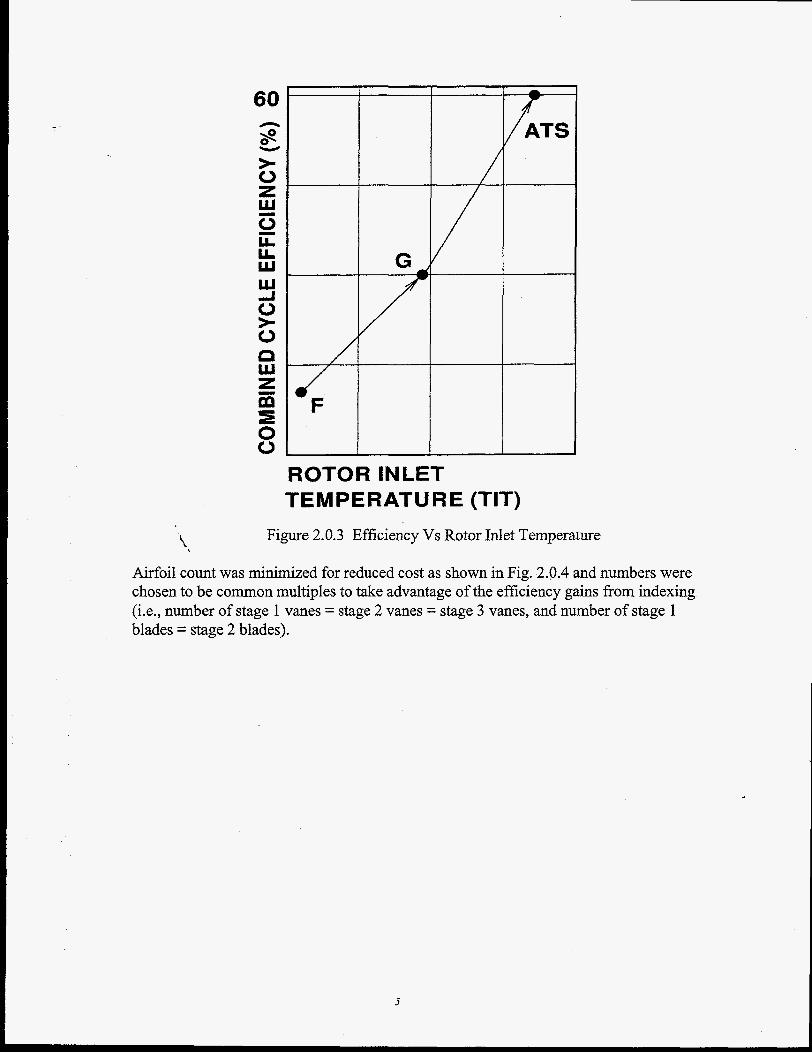
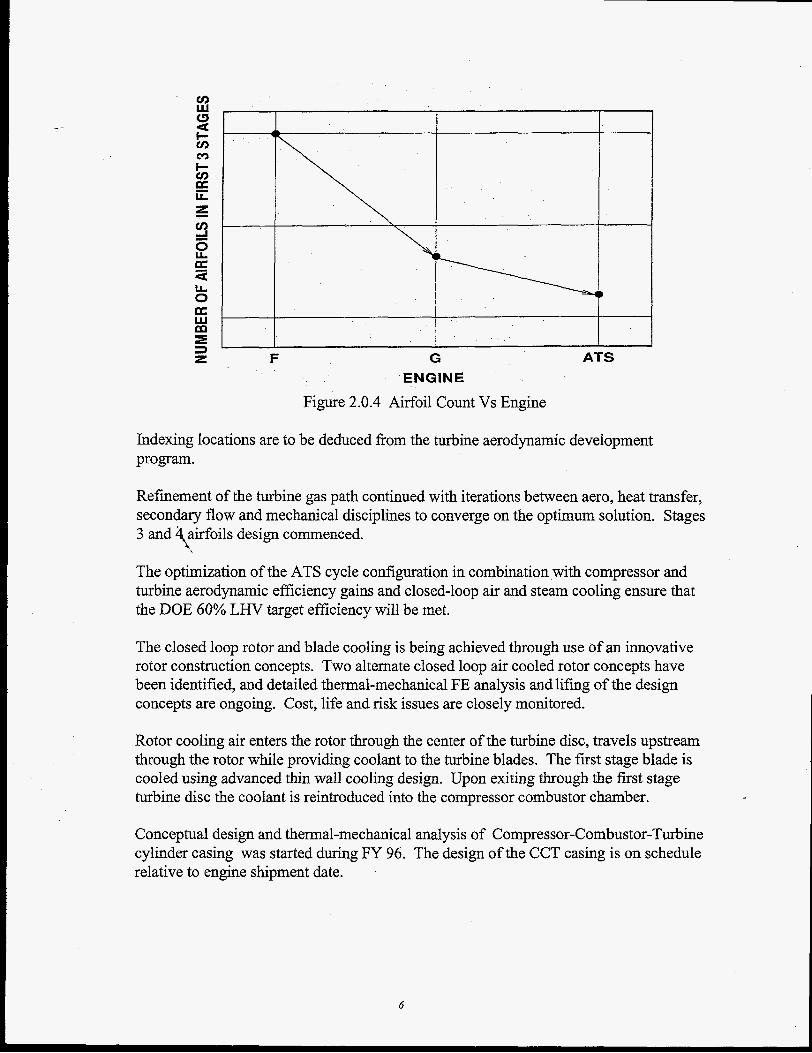
Airfoil count was minimized for reduced cost as shown in Fig. 2.0.4 and numbers were chosen to be common multiples to take advantage of the efficiency gains from indexing (Le., number of stage 1 vanes = stage 2 vanes = stage 3 vanes, and number of stage 1 blades = stage 2 blades).
5
F
r
ATS G ENGINE
Figure 2.0.4 Airfoil Count Vs Engine
Indexing locations are to be deduced from the turbine aerodynamic development program.
Refinement of the turbine gas path continued with iterations between aero, heat transfer, secondary flow and mechanical disciplines to converge on the optimum solution. Stages 3 and airfoils design commenced.
The optimization of the ATS cycle configuration in combination with compressor and turbine aerodynamic efficiency gains and closed-loop air and steam cooling ensure that the DOE 60% LHV target efficiency will be met.
\,
The closed loop rotor and blade cooling is being achieved through use of an innovative rotor construction concepts. Two alternate closed loop air cooled rotor concepts have been identified, and detailed thermal-mechanical FE analysis and lifmg of the design concepts are ongoing. Cost, life and risk issues are closely monitored.
Rotor cooling air enters the rotor through the center of the turbine disc, travels upstream through the rotor while providing coolant to the turbine blades. The frst stage blade is cooled using advanced thin wall cooling design. Upon exiting through the first stage turbine disc the coolant is reintroduced into the compressor combustor chamber.
Conceptual design and thermal-mechanical analysis of Compressor-Combustor-Turbine cylinder casing was started during FY 96. The design of the CCT casing is on schedule relative to engine shipment date.
First two turbine stators and transition piece are closed loop steam cooled, while stage 3 is open loop air cooled. First stage vane segment uses innovative thin wall cooling concepts which will improve engine performance and component life.
Conceptual design of turbine vane segments and support structure was initiated during FY 96, design effort is on schedule relative to engine shipment date.
3.0 SPECIFICATION AND DESIGN OF POWER PLANT EQUIPMENT
Activities for power plant design were initiated in the second quarter. The plant conceptual layout is based upon the 240 MW Reference Plant. The design incorporates flexible proven design features that minimizes design changes usually required for customizing the plant to local conditions. The 240 MW Reference Plant uses multiple separate shafts and separate generators. After considerable debate, a single shaft approach was specified for the ATS plant. The ATS design requires a single shaft for both combustion and steam turbines and a single generator coupled to the same shaft. The effect of this approach on starting procedures, starting torque and off normal operation is not completely understood. Design areas where the single shaft approach might effect are in the process of being identified.
The heat recovery steam generator (HRSG) specifications were drafted. A natural circulation, triple pressure unit with vacuum deaeration type unit was delineated. No specialkaterials were required. Materials are commercial grade commonly used in boilers today. Design criteria will require application of the ASME Pressure Vessel Code.
The low pressure steam turbine will be flanked by twin side entry saddle bag condensers. The ATS plant necessitates the use of a double flow LP exhaust. Operational design criteria for the steam turbine include up to 50 starts per year and 8000 hours per year of base load operation.
8.0 INTEGRATED PROGRAM PLAN
The draft Integrated Program Plan was developed and submitted on March 8,1996. Comments on the draft were received on May 29, 1996. The final Integrated Program Plan was completed August 8, 1996 and re-submitted August 13, 1996.
7
9.1 CLOSED LOOP COOLING
The ATS feature producing the greatest performance improvement over that of previous combined cycle configurations is closed loop cooling. The benefit of closed loop cooling lies in the reduction of the discharge of spent cooling flow into the turbine blade path, along with the transfer of heat energy to points in the cycle from which maximum useful work can be recovered. Relative to conventional open loop cooling, this reduction of flow effectively 1) raises the mass flow entering the turbine, 2) raises the relative gas temperatures entering each of the downstream stages, and 3) reduces the momentum losses associated with the mixing of cooling flow with the gas path,
On the turbine component level, the challenge of closed loop cooling is in meeting the extremely high cooling requirements of the ATS topping cycle while sacrificing the benefits of film cooling. Without film cooling, the hot parts design must take advantage of other techniques available, namely:
1. Enhanced cool side heat transfer 2. Thermal barrier coating systems 3. Thin wall manufacturing methods 4. Cooled coolant supplies 5. Gas path geometries which minimize hot side heat transfer.
During FY96, the basic cooling techniques for the turbine hot parts were determined. The design of the stage 1 vane was developed to the point of release of the casting data base towe casting vendor. The stage 1 blade design development was following that of the stage 1 vane, on schedule. Both of these components will employ advanced thin wall casting configurations (see the following section describing Task 9.2). These two rows will also employ all the other cooling techniques listed above. Because of reduced cooling requirements and cost benefit considerations, the downstream rows employ the listed items to lesser degrees. Although the stage 1 and 2 vanes are intended to be steam cooled, they are being designed to also meet the objectives with air as the coolant.
A key element in the closed loop cooling development is the high pressure, high temperature hot cascade test program. The intent of the test program is to test the cooling concepts in an engine scale component at engine operating conditions, using either steam or air as coolants. The tested component will be the stage 1 vane employing the actual airfoil and shroud cooling schemes designed for the engine. The objectives of the test program are to:
1. Verify the closed loop cooling designs 2. Confirm the capability of operating with either steam or air as coolant 3. Quantify the cooling performances of the various circuits 4. Provide data to refine and optimize the cooling designs 5. Test, verify and refine the transition mouth seal design.
8
Because of the high temperature, pressure and flow requirements, the Arnold Engineering Development Center (AEDC) has been chosen as the test site. As of the end of FY ’96 the test rig design effort at the Westinghouse Science and Technology Center (STC), and facility design at AEDC were progressing on schedule. As a cost saving measure the rig is being designed to also perform the combustion testing program (see the following section describing Task 9.8).
The program is currently on schedule with only one milestone objective that was to be achieved by year’s end. That milestone was to issue the Test Requirements Report by 5/1/96, which was accomplished on that date. All other milestones are expected to be met on schedule.
9.2 THIN WALL CASTING DEVELOPMENT
The primary purpose of the thin wall casting program is to develop thin wall airfoils that meet the following requirements:
0 Allows closed loop cooling to be used in an optimum fashion.
0 Has the capability to be manufactured in a production environment at a commercially feasible cost.
0 .\Will result in airfoils which maintain structural integrity for the required product h e .
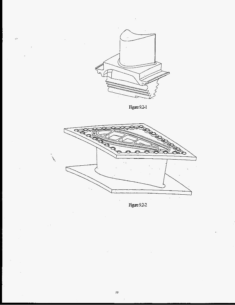
During the 1996 fiscal year, the major barrier issues impacting thin wall airfoils have been mitigated. Conceptual design work for the test vane has been completed in fiscal 1996 with aero, heat transfer, structural, and manufacturing engineers working in a concurrent manner to establish a comprehensive design solution. The test vane manufacturing vendor has been selected and the required aero, thermal, and structural analysis has been completed. The test vane drawing has been issued and the vendor has procured the tooling required to fabricate the first casting. All indications remain positive for the first piece of metal turbine hardware in the Westinghouse ATS program “ test vane 1’’ to be delivered in March of 1997. The first prototype blade design is also in progress. During fiscal 1996 the blade design team has also completed the necessary aero, thermal, and structural analysis to mitigate the design risks. The first prototype blade drawing is on schedule to be released January 1997. The blade and vane geometries are shown below in Figures 9.2-1 and 9.2-2, respectively.
9
Figlae 9.2-1
F i p 92-2
10
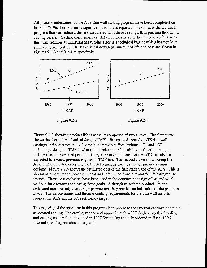
All phase 3 milestones for the ATS thin wall casting program have been completed on time in FY 96. Perhaps more significant than these reported milestones is the technical progress that has reduced the risk associated with these castings, thus pushing though the casting barrier. Casting these single crystaUdirectionally solidified turbine airfoils with thin wall features at industrial gas turbine sizes is a technical barrier which has not been achieved prior to ATS. The two critical design parameters of life and cost are shown in Figures 9.2-3 and 9.2-4, respectively.
-~
L I F E
ATS
1990 1995 2000 1990 1995 2000
YEAR YEAR
Figure 9.2-3 Figure 9.2-4
Figure‘9.2.3 showing product life is actually composed of two curves. The first curve shows the thermal mechanical fatigue(TMF) life expected from the ATS thin wall castings and compares this value with the previous Westinghouse “F” and “G” technology designs. TMF is what often limits an airfoils ability to function in a gas turbine over an extended period of time, the curve indicate that the ATS airfoils are expected to exceed previous engines in TMF life. The second curve shows creep life. Again the calculated creep life for the ATS airfoils exceeds that of previous engine designs. Figure 9.2.4 shows the estimated cost of the first stage vane of the ATS. This is shown as a percentage increase in cost and referenced from “F” and “G’ Westinghouse frames. These cost estimates have been used in the concurrent design effort and work will continue towards achieving these goals. Although calculated product life and estimated cost are only two design parameters, they provide an indication of the progress made. The aerodynamic and thermal cooling requirements for the thin wall airfoils support the ATS engine 60% efficiency target.
The majority of the spending in this program is to purchase the external castings and their associated tooling. The casting vendor and approximately 400K dollars worth of tooling and casting costs will be invoiced in 1997 for tooling actually ordered in fiscal 1996. Internal spending remains as targeted.
Westinghouse is confident that the design efforts in the past year have made significant progress towards eliminating the casting barrier issues and will result in “first of a kind” industrial gas turbine airfoils.
9.3 ROTOR AIR SEALING DEVELOPMENT
Task 9.3 addresses achieving low leakages in the closed-loop air rotor cooling flow system. This flow system provides cooled, high pressure air to the four rows of turbine blades for cooling, and then returns the air to the combustor shell. Tight sealing is required at interfaces in the flow circuits, Le., where air enters the rotor center at the rear; between rotor disks, i.e., “belly bands” between disk arms and at the blade roots; and at the blade roots where the blades are attached to the turbine rotor disks. Leakage is exacerbated by the high air pressure maintained throughout the circuit so that the air can be returned to the combustor shell. In this task, design approaches are being sought to meet the tight sealing requirements. For sealing between rotating parts, conceptual design schemes are devised and final approaches derived with consultation from seal vendors. This effort is done in concert with the turbine design. The rotor rear seal, where the cooling air enters the rotor, is an especially critical seaIing location. Here, a near zero leakage, advanced air seal is needed. A key challenge to this sealing location is the large relative axial motion between the rotor and surrounding housinqduring engine start up and shut down. Advantages of this location are a low air temperattue, seal not being segmented, and a relatively small size for minimal leakage area.
The prime candidate for the rotor rear seal is a face seal. Face seals are used in many aero gas turbines and other turbomachinery applications. They consist of two flat annular ring surfaces running in close proximity axially; one is attached to the rotating shaft and the other to a stationary housing. They are designed to have a very small axial clearance despite shaft movement, wobble (called “swash”), etc., in order to maintain near zero leakage rates. Hydrostatic or hydrodynamic approaches are employed to maintained the small clearances. One of the surfaces is usually made of carbon because of its excellent wear and machinability characteristics. Springs or other mechanical devices aid in maintaining a small gap.
Task Description The primary focus of Task 9.3 is designing and validating a rotor rear seal, since sealing between the rotating parts is being done in concert with turbine design. The approach taken is to: (1) define the rear seal requirements; (2) solicit competing vendor proposals for the seal; (3) select a vendor via. a detailed evaluation against the requirements; and (4) fund one vendor to design, build, and rig test two seals. The test hardware would subsequently be the prime and spare rear seals for the first ATS engine.
12
1996 Pronress/Plans
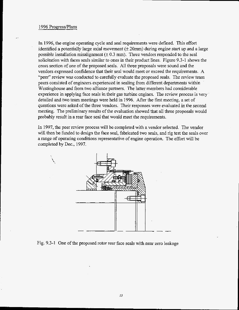
In 1996, the engine operating cycle and seal requirements were defined. This effort identified a potentially large axial movement (-+ 20mm) during engine start up and a large possible installation misalignment (+ 0.3 mm). Three vendors responded to the seal solicitation with faces seals similar to ones in their product lines. Figure 9.3-1 shows the cross section of one of the proposed seals. All three proposals were sound and the vendors expressed confidence that their seal would meet or exceed the requirements. A “peer” review was conducted to carefully evaluate the proposed seals. The review team peers consisted of engineers experienced in sealing from different departments within Westinghouse and from two alliance partners. The latter members had considerable experience in applying face seals in their gas turbine engines. The review process is very detailed and two team meetings were held in 1996. After the first meeting, a set of questions were asked of the three vendors. Their responses were evaluated in the second meeting. The preliminary results of the evaluation showed that all three proposals would probably result in a rear face seal that would meet the requirements.
In 1997, the peer review process will be completed with a vendor selected. The vendor will then be funded to design the face seal, fabricated two seals, and rig test the seals over a range of operating conditions representative of engine operation. The effort will be completed by Dec., 1997.
Fig. 9.3-1 One of the proposed rotor rear face seals with near zero leakage
13
- -
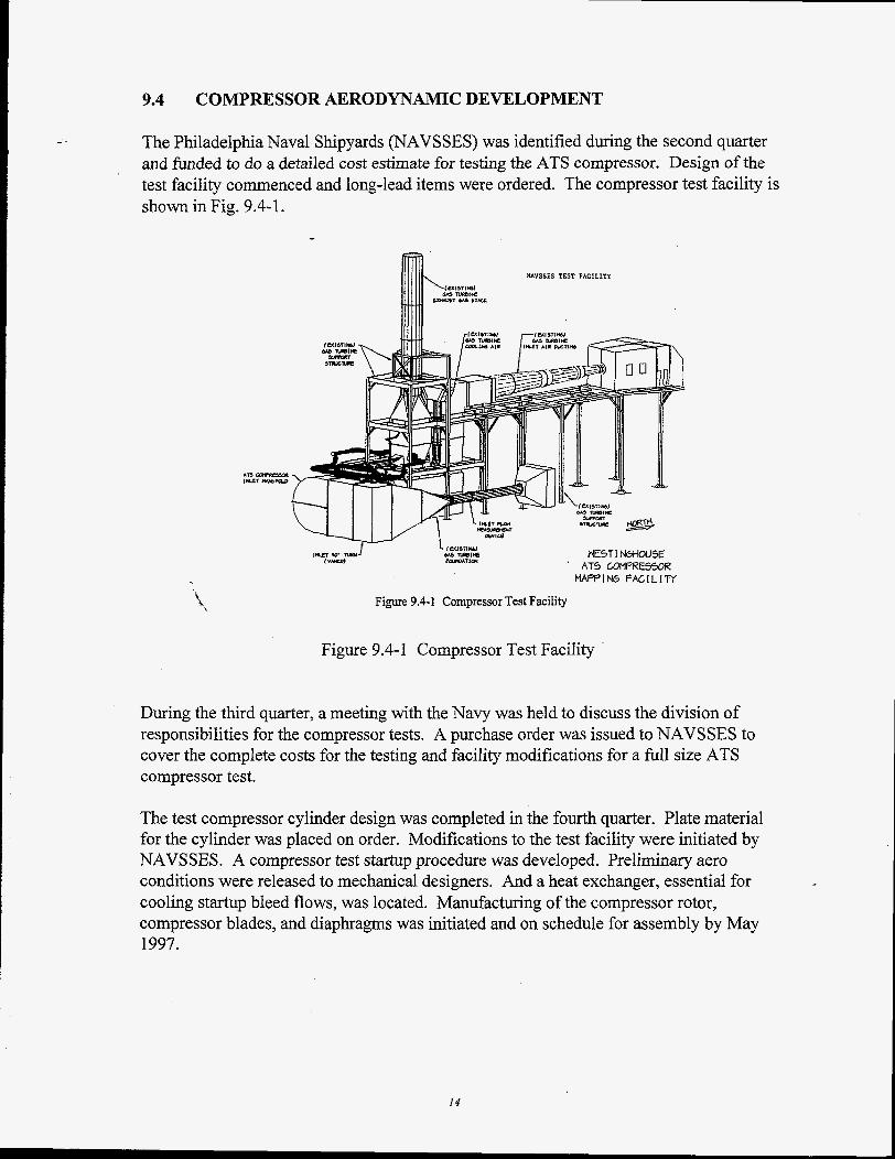
9.4 COMPRESSOR AERODYNAMIC DEVELOPMENT
The Philadelphia Naval Shipyards (NAVSSES) was identified during the second quarter and funded to do a detailed cost estimate for testing the ATS compressor. Design of the test facility commenced and long-lead items were ordered. The compressor test facility is shown in Fig. 9.4-1.
NAVSSES TEST FACILITY
w E S T 1 N6HoUsE ' AT5 LOMPUE5WiZ f V W J w i i m
MAPPING FACILITY
Figure 9.4-1 Compressor Test Facility
Figure 9.4- 1 Compressor Test Facility
During the third quarter, a meeting with the Navy was held to discuss the division of responsibilities for the compressor tests. A purchase order was issued to NAVSSES to cover the complete costs for the testing and facility modifications for a full size ATS compressor test.
The test compressor cylinder design was completed in the fourth quarter. Plate material for the cylinder was placed on order. Modifications to the test facility were initiated by NAVSSES. A compressor test startup procedure was developed. Preliminary aero conditions were released to mechanical designers. And a heat exchanger, essential for cooling startup bleed flows, was located. Manufacturing of the compressor rotor, compressor blades, and diaphragms was initiated and on schedule for assembly by May 1997.
14
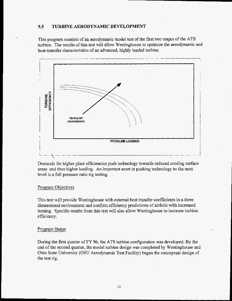
9.5 TURBINE AERODYNAMIC DEVELOPMENT
This program consists of an aerodynamic model test of the first two stages of the ATS turbine. The results of this test will allow Westinghouse to optimize the aerodynamic and heat-transfer characteristics of an advanced, highly loaded turbine.
PITCHUNE LOPDING
L '\ Demands for higher plant efficiencies push technology towards reduced cooling surface areas and thus higher loading. An important asset in pushing technology to the next level is a full pressure ratio rig testing.
Program Objectives
This test will provide Westinghouse with external heat transfer coefficients in a three dimensional environment and confirm efficiency predictions of airfoils with increased turning. Specific results from this test will also allow Westinghouse to increase turbine efficiency.
Program Status
During the first quarter of FY 96, the ATS turbine configuration was developed. By the end of the second quarter, the model turbine design was completed by Westinghouse and Ohio State University (OSU Aerodynamic Test Facility) began the conceptual design of the test rig.
15
During the third quarter, a review meeting with OSU was held to develop test procedures, objectives and schedule. It was decided to test stage 1 first and then test the two stages together so as to compress the test schedule. Stage 1 aluminum test vane and blade were machined to verifl the steel airfoil manufacturing process. The test rig design was in progress and the rotor disks design was completed.
The stage 1 blades and vanes were received at Calspan (Instrumentation Facility) during the fourth quarter. The dimensions for stage 1 airfoils were verified at the Winston- Salem airfoil manufacturing facility. Stage 2 airfoil machining and disk forgings were initiated and completion date supports OSU need date. Costs were well within anticipated spending profile both for Westinghouse and outside suppliers.
During the year, non-steady computational fluid dynamics (CFD) analysis was ongoing at OSU and at the Westinghouse Science and Technology Center. These CFD studies will be used in the analysis of the rig test results and also provide a calibrated tool for future turbine designs.
- -
I , I
9.6 ADVANCED AIR SEALING DEVELOPMENT
Task 9.6 is a continuation of Phase 2 Tasks 8.23, 8.24, and 8.29. The overall objective is to design and validate advanced air seals for several critical locations in the ATS combustion turbine. These advanced seals will reduce leakage flow rates andor minimize hot gas ingestion into disk cavities to improve engine and hence power plant efficienhes while meeting design, life, durability, and cost requirements. In this task, advanced air seals are being developed, rig tested, and validated in engine and component tests. Engine locations considered are: beneath the compressor diaphragms, along the torque tube, in the turbine interstages, in front of the first turbine rotor, and at the rims of the inner flow path ahead and behind the turbine blade rows. These seals will pass less leakage flow than current labyrinth seals while withstanding the large relative radial and axial movements during engine start-up and shut down for a plus 25,000 now operating life. The seals will also be rugged for handling and installation in an industrial engine environment. The prime candidates for advanced air sealing are brush seals. These seals are being incorporated into aero gas turbines. They restrict airflow between mating rotating and stationary components by filling the gaps with a brush of very fine wire bristles, angled in the direction of rotation. Running line-to-line with the rotating surface, they have been found to leak considerably less than labyrinth seals with normal operating clearances. However, brush seals must be carefully designed so that they operate through the engine operation range without excessive wear or damage.
16
- -
Task Description
The ATS advanced air sealing efforts include: (1) a preliminary investigation of the benefits, potential locations, feasibility of running against uncoated surfaces, and validation required in applying brush seals to CT’s, (2) focused development efforts for selected ATS engine locations, and (3) validation of full-size brush seals in the ATS compressor rig and field engines. The total cost of the Phase 2 and 3 advanced air sealing efforts is about 1 million dollars.
The primary seal vendor to support the seal development work has been selected. The vendor’s tasks include: concept studies, tribology testing, detailed seal design, fabrication and rig testing candidate brush seals for the focuses development; and fabrication of full-size hardware for field validations.
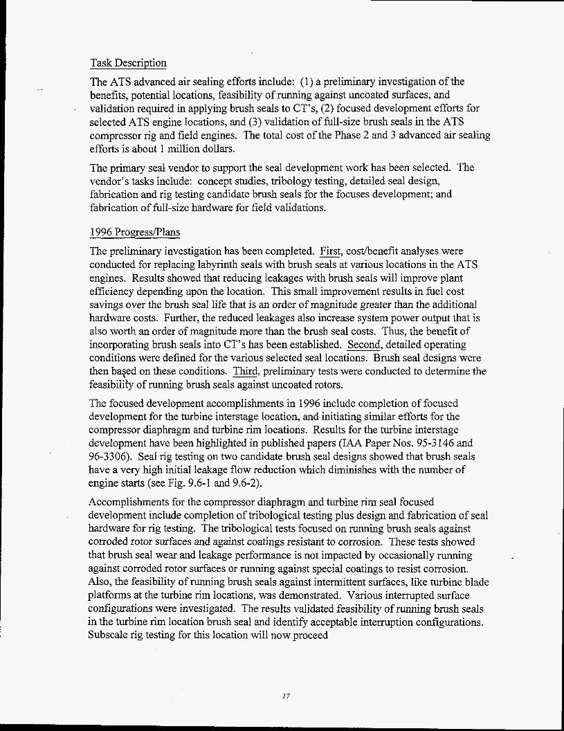
1996 ProgressPlans I The preliminary investigation has been completed. First, costhenefit analyses were conducted for replacing labyrinth seals with brush seals at various locations in the ATS engines. Results showed that reducing leakages with brush seals will improve plant efficiency depending upon the location. This small improvement results in fuel cost savings over the brush seal life that is an order of magnitude greater than the additional hardware costs. Further, the reduced leakages also increase system power output that is also worth an order of magnitude more than the brush seal costs. Thus, the benefit of incorporating brush seals into CT’s has been established. Second, detailed operating conditions were defined for the various selected seal locations. Brush seal designs were then baqed on these conditions. Third, preliminary tests were conducted to determine the feasibilib of running brush seals against uncoated rotors. The focused development accomplishments in 1996 include completion of focused development for the turbine interstage location, and initiating similar efforts for the compressor diaphragm and turbine rim locations. Results for the turbine interstage development have been highlighted in published papers (IAA Paper Nos. 95-3 146 and 96-3306). Seal rig testing on two candidate brush seal designs showed that brush seals have a very high initial leakage flow reduction which diminishes with the number of engine starts (see Fig. 9.6-1 and 9.6-2). Accomplishments for the compressor diaphragm and turbine rim seal focused development include completion of tribological testing plus design and fabrication of seal hardware for rig testing. The tribological tests focused on running brush seals against corroded rotor surfaces and against coatings resistant to corrosion. These tests showed that brush seal wear and leakage performance is not impacted by occasionally running against corroded rotor surfaces or running against special coatings to resist corrosion. Also, the feasibility of running brush seals against intermittent surfaces, like turbine blade platforms at the turbine rim locations, was demonstrated. Various interrupted surface configurations were investigated. The results validated feasibility of running brush seals in the turbine rim location brush seal and identi9 acceptable interruption configurations. Subscale rig testing for this location will now proceed
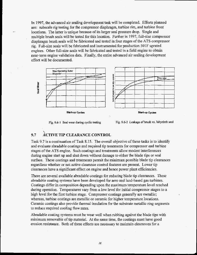
In 1997, the advanced air sealing development task will be completed. Efforts planned are: subscale rig testing for the compressor diaphragm, turbine rim, and turbine front locations. The latter is unique because of its larger seal pressure drop. Single and multiple brush seals will be tested for this location. Further in 1997, full-size compressor diaphragm brush seals will be fabricated and tested in four stages of the ATS compressor rig. Full-size seals will be fabricated and instrumented for production 501F uprated engines. Other full-size seals will be fabricated and tested in a field engine to obtain near-term engine validation data. Finally, the entire advanced air sealing development effort will be documented.
- -
.
Start-up Cycles
Fig. 9.6-1 Seal wear during cyclic testing
I I I I I I start-up Cycles
Fig. 9.6-2 Leakage of brush vs. labyrinth seal
9.7 ACTIVE TIP CLEARANCE CONTROL Task 9.7 is a continuation of Task 8.15. The overall objective of these tasks is to identify and evaluate abradable coatings and required tip treatments for compressor and turbine stages of the ATS engine. Such coatings and treatments allow modest interferences during engine start up and shut down without damage to either the blade tips or seal surface. These coatings and treatments permit the minimum possible blade tip clearances regardless whether or not active clearance control features are present. Lower tip clearances have a significant effect on engine and hence power plant efficiencies.
There are several available abradable coatings for reducing blade tip clearances. These abradable coating systems have been developed for aero and land-based gas turbines. Coatings differ in composition depending upon the maximum temperature level reached during operation. Temperatures vary from a low level for initial compressor stages to a high level for the first turbine stage. Compressor coatings generally are metallic; whereas, turbine coatings are metallic or ceramic for higher temperature locations. Ceramic coatings also provide thermal insulation for the substrate metallic ring segments to reduce required cooling flow rates. Abradable coating systems must be wear well when rubbing against the blade tips with minimum removable of tip material. At the same time, the coatings must have good erosion resistance. Both of these effects are necessary to maintain clearances for a
18
minimum of 25,000 hours of operation. Ceramic abradable coatings have poorer abradable properties so that blade tip treatments are often necessary. Blade tip wear is worsen by low rates of incursion of the blade tips movement into the coatings. For large industrial engines, start up speed is slow due to the massive rotor sizes. Consequently, incursion rates are lower and blade tip wear is more of an issue than in smaller gas turbine engines.
Task Description The focus of the abradable coating portion of Task 9.7 is to define and evaluate coatinghip treatment systems. This involves transitioning available technology. Both compressor and turbine coatings are considered, as well as tip treatments for running against ceramic coatings. Defining coating systems involves reviewing available coatings against requirements. Evaluations are then conducted of candidate abradable coating systems. Rig tests are funded to determine abradability and erosion resistance for representative engine operating conditions. Shock resistance is also tested for ceramic coatings.
1996 Progress/Plans
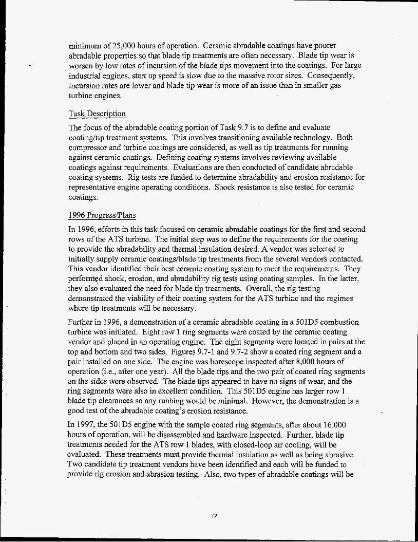
In 1996, efforts in this task focused on ceramic abradable coatings for the first and second rows of the ATS turbine. The initial step was to define the requirements for the coating to provide the abradability and thermal insulation desired. A vendor was selected to initially supply ceramic coatingshlade tip treatments from the several vendors contacted. This vendor identified their best ceramic coating system to meet the requirements. They pe r fomd shock, erosion, and abradability rig tests using coating samples. In the latter, they also evaluated the need for blade tip treatments. Overall, the rig testing demonstrated the viability of their coating system for the ATS turbine and the regimes where tip treatments will be necessary. Further in 1996, a demonstration of a ceramic abradable coating in a 501D5 combustion turbine was initiated. Eight row 1 ring segments were coated by the ceramic coating vendor and placed in an operating engine. The eight segments were located in pairs at the top and bottom and two sides. Figures 9.7-1 and 9.7-2 show a coated ring segment and a pair installed on one side. The engine was borescope inspected after 8,000 hours of operation (Le., after one year). All the blade tips and the two pair of coated ring segments on the sides were observed. The blade tips appeared to have no signs of wear, and the ring segments were also in excellent condition. This 501D5 engine has larger row 1 blade tip clearances so any rubbing would be minimal. However, the demonstration is a good test of the abradable coating’s erosion resistance. In 1997, the 501D5 engine with the sample coated ring segments, after about 16,000 hours of operation, will be disassembled and hardware inspected. Further, blade tip treatments needed for the ATS row 1 blades, with closed-loop air cooling, will be evaluated. These treatments must provide thermal insulation as well as being abrasive. Two candidate tip treatment vendors have been identified and each will be funded to provide rig erosion and abrasion testing. Also, two types of abradable coatings will be
19
evaluated for the ATS compressor. One is for the initial, lower temperature stages and the other for the latter, higher temperature stages. The evaluation will include erosion and abradability rig testing and full-scale assessment in the ATS compressor rig test. The effort including a final report will be completed by Dec., 1997.
_ -
Fig. 9.7-1 501D5 coated ring segments Fig. 9.7-2 Installed pair of coated segments
9.8 COMBUSTION SYSTEM DEVELOPMENT
Excellent progress has been made on the design of the combustion system this year. The two prhary designs, Piloted Ring and Multiswirl have completed comprehensive test programs at various conditions to establish the optimum choice for the ATS engine. Based on the superior high temperature capability , the Piloted Ring has been chosen as the base design for the ATS engine. Emission capabilities to single digit NOx level are considered difficult but achievable with this design. Detail design of the ATS combustor, based on the extensive development of the base design, is underway for the ATS prototype hardware. An upgraded test rig is being manufactured for full pressure verification that will allow testing to full ATS temperatures.
Westinghouse and another combustor vendor also developed and tested catalytic components that demonstrated improved stability and lower emissions. Catalytically enhanced designs are a primary focus for the ATS engine as a complement to the Piloted Ring design. A long term agreement was signed with the same vendor to commercialize catalytic designs for the ATS engine. The combined technologies of the Piloted ring coupled with catalytic combustion provide the basis for meeting the ATS engine requirements of 9 ppm. We anticipate full condition testing of the catalytic components in 1997.
Support programs also provided additional benefits to the program. The, active noise control program with Georgia Tech completed demonstration in our mid pressure facility and demonstrated a fourfold reduction in noise levels with this technology. The scaling of
20
- -
this technology to full engine conditions would be the next step in advancing this valuable technology. The other key support program was the advancement of the fuel/air measurement probe with Penn State University. This probe was tested in a full size combustor and demonstrated the capability to measure local fuel/air ratios within an operating combustor. This technology can provide a benefit to fine tuning the base design for the Ultra Low NOx ATS designs.
The advances this year provide the basis for detail design efforts on the ATS combustor We fully expect to complete this development on schedule to meet the engine shipment requirements and satisfy the low emission requirements of the ATS engine.
9.9 CERAMIC RING SEGMENT
During FY96, several aspects of the ceramic matrix composite (CMC) application to combustion turbine (CT) components were investigated. These are as follows:
Manufacturing development
Generation of design data base for Nicalon Alumina@ CMC for potential use in ring segments Conceptual and preliminary design studies of a CMC ring segment
Development of the ceramic abradable/insulation layer for the Nicalon Alumina CMC
Generation of Design Database \
W-PGBU started the testing at O W L (Oak Ridge National Lab, High Temperature Materials Laboratory ) and UDRI (University of Dayton Research Institute) in December 1995. Creep rupture test matrix was selected to provide rapid information about the CMC behavior under certain loading conditions, and also to supplement the material data obtained from others.
The test matrix completed and in progress as of September 96 is as summarized in Table 1.
21
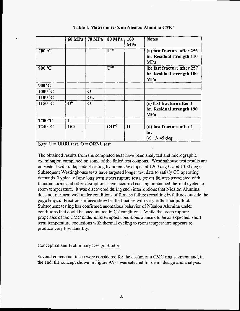
Table 1. Matrix of tests on Nicalon Alumina CMC
60MPa 70MPa 80MPa 100 Notes MPa
700 "C U'"' (a) fast fracture after 256 hr. Residual strength 110 MPa
800 "C U(b) (b) fast fracture after 257 hr. Residual strength 100 MPa
900 "C 1000 "C 0 1100 "C ou 1150 "C ()(a 0 (c) fast fracture after 1
hr. Residual strength 190 MPa
1200 "C U U 1240 "C 00 00''' 0 (d) fast fracture after 1
hr. (e) +/- 45 deg
Key: U = UDlU test, 0 = ORNL test
The obtained results from the completed tests have been analyzed and micrographic examinhion completed on some of the failed test coupons. Westinghouse test results are consisteit with independent testing by others developed at 1200 deg C and 1300 deg C. Subsequent Westinghouse tests have targeted longer test data to satisfy CT operating demands. Typical of any long term stress rupture tests, power failures associated with thunderstorms and other disruptions have occurred causing unplanned thermal cycles to room temperature. It was discovered during such interruptions that Nicalon Alumina does not perform well under conditions of furnace failures resulting in failures outside the gage length. Fracture surfaces show brittle fracture with very little fiber pullout. Subsequent testing has confirmed anomaIous behavior of Nicalon Alumina under conditions that could be encountered in CT conditions. While the creep rupture properties of the CMC under uninterrupted conditions appears to be as expected, short term temperature excursions with thermal cycling to room temperature appears to produce very low ductility.
Conceptual and Preliminary Design Studies
Several conceptual ideas were considered for the design of a CMC ring segment and, in the end, the concept shown in Figure 9.9-1 was selected for detail design and analysis.
22
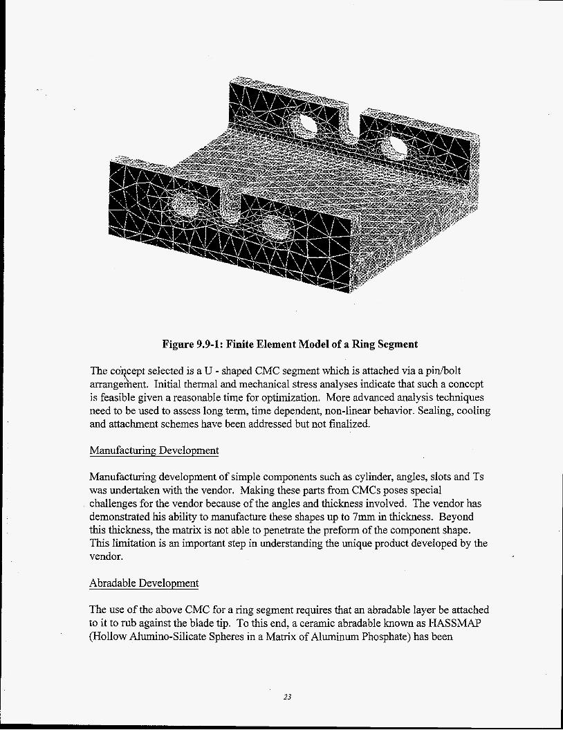
Figure 9.9-1: Finite Element Model of a Ring Segment
The co+cept selected is a U - shaped CMC segment which is attached via a pin/bolt arrangerhent. Initial thermal and mechanical stress analyses indicate that such a concept is feasible given a reasonable time for optimization. More advanced analysis techniques need to be used to assess long term, time dependent, non-linear behavior. Sealing, cooling and attachment schemes have been addressed but not finalized.
Manufacturing Development
Manufacturing development of simple components such as cylinder, angles, slots and Ts was undertaken with the vendor. Making these parts from CMCs poses special challenges for the vendor because of the angles and thickness involved. The vendor has demonstrated his ability to manufacture these shapes up to 7mm in thickness. Beyond this thickness, the matrix is not able to penetrate the preform of the component shape. This limitation is an important step in understanding the unique product developed by the vendor.
Abradable Development
The use of the above CMC for a ring segment requires that an abradable layer be attaclled to it to rub against the blade tip. To this end, a ceramic abradable known as H A S S W (Hollow Alumino-Silicate Spheres in a Matrix of Aluminum Phosphate) has been
23
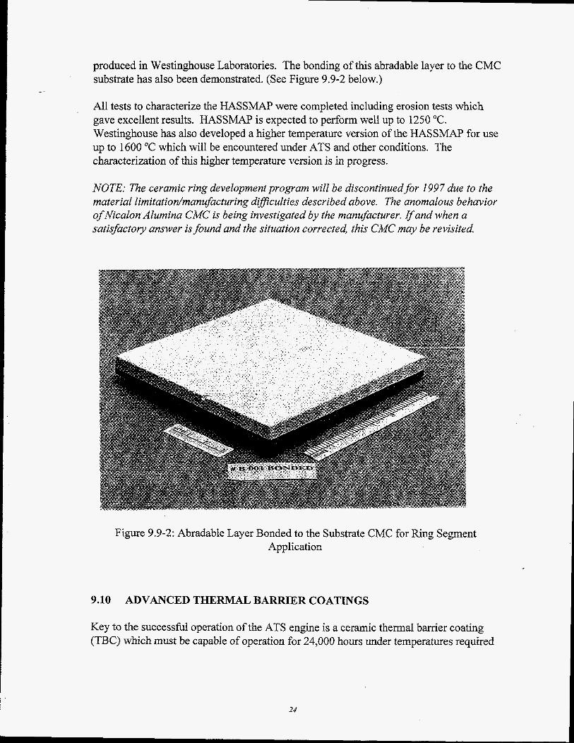
produced in Westinghouse Laboratories. The bonding of this abradable layer to the CMC substrate has also been demonstrated. (See Figure 9.9-2 below.)
All tests to characterize the HASSMAP were completed including erosion tests which gave excellent results. HASSMAP is expected to perform well up to 1250 "C. Westinghouse has also developed a higher temperature version of the HASSMAP for use up to 1600 "C which will be encountered under ATS and other conditions. The characterization of this higher temperature version is in progress.
- -
NOTE: The ceramic ring development program will be discontinued for 1997 due to the material limitatiodmanufacturing dificulties described above. The anomalous behavior of Nicalon Alumina CMC is being investigated by the manufacturer. Ifand when a satisfactory answer is found and the situation corrected, this CMC may be revisited
Figure 9.9-2: Abradable Layer Bonded to the Substrate CMC for Ring Segment Application
9.10 ADVANCED THERMAL BARRIER COATINGS
Key to the successful operation of the ATS engine is a ceramic thermal barrier coating (TBC) which must be capable of operation for 24,000 hours under temperatures required
24
to meet ATS efficiency goals. The focus of this effort is to evaluate the performance of bond coat alloys and new ceramics to meet these goals.
Three nickel base superalloys were selected as substrate materials for the evaluation of several commercial TBC systems. The nominal alloy composition of each substrate is provided in Table 1. Each of these alloys received a conventional bond coat, of nominal thickness. RTl22 is a low pressure plasma sprayed (LPPS) MCrAlY (Co,~Ni,,Cr,,Al,Y,,) fabricated by Chromalloy Turbine Technologies. The Howmet 150L coating, a Chemical Vapor Deposition (CVD) PtAl produced by Howmet Inc., was evaluated on MarM-002 and IN-939. An air plasma sprayed (APS) 8% yttria stabilized zirconia TBC, 10 mil (0.25 mm) nominal thickness, was applied to each system. An electron-beam physical vapor deposition (EB-PVD) coating, Chromalloy RT33, was applied in several cases. A summary of the systems evaluated is given in Table 2.
Coating performance was based on the time to failure in furnace tests. Furnace exposure tests were conducted at 2102°F (1 150OC). Samples were cooled to room temperature in static air once every 24 hours. Samples were removed from the test at prescribed intervals for metallographic inspection. At least three specimens for each system were tested to failure. Coating failure was defined as significant spallation of the coating. Coating system performance is summarized in Fiewe 9.10-1.
It has been determined through these evaluations that the unique chemistry and properties of each coating system effect coating performance. The critical life-limiting factor for TBC systems is oxidation of the bond coat. The oxidation rate is dictated by the capacity of the bond coat to form an impermeable, adherent alumina oxide scale. Diffusion of elements from the substrate will influence the ability of the coating to form a protective oxide scale.
1
The difference in performance between these systems can be related to the effect of the substrate on oxide chemistry and morphology. The RTl22 on MarM-002 with an APS TBC (RMA) had the longest life of the three RT1221 APS coatings, Figure 1. The oxide formed on this system is characterized by an adherent, pure alumina layer containing a trace amount of Y203 and significant mount of HfO,. The Howmet 15OL / EB-PVD system on MarM-002 developed a thin alumina scale with large amounts of hafnia, Figure 9.10-2. The hafnium difises from the substrate and is incorporated in the oxide scale. While it is well established that the incorporation of rare earth elements into the oxide scale improves oxide adherence the significant amount of hafhia formed within the oxide may compromise the protective capacity of the scale.
25
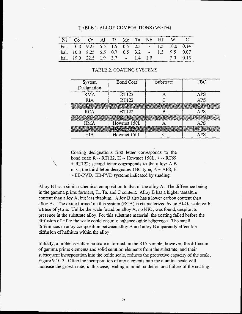
TABLE 1. ALLOY COMPOSITIONS (WGT%)
Ni Co Cr A1 Ti Mo Ta Nb Hf W C bal. 10.0 9.25 5.5 1.5 0.5 2.5 - 1.5 10.0 0.14 bal. 10.0 8.25 5.5 0.7 0.5 3.2 - 1.5 9.5 0.07 bal. 19.0 22.5 1.9 3.7 - 1.4 1.0 - 2.0 0.15
TABLE 2. COATING SYSTEMS
RT122 C APS
System Bond Coat Substrate TBC Designation
RMA RT122 A APS RIA
HIA I Howmet 150L I C I A P S
Coating designations first letter corresponds to the bond coat: R - RT122, H - Howmet 150L, + - RT69 + RT122; second letter corresponds to the alloy: A,B or C; the third letter designates TBC type, A - A P S , E - EB-PVD. EB-PVD systems indicated by shading.
Alloy B has a similar chemical composition to that of the alloy A. The difference being in the gamma prime formers, Ti, Ta, and C content. Alloy B has a higher tantalum content than alloy A, but less titanium. Alloy B also has a lower carbon content than alloy A. The oxide formed on this system (RCA) is characterized by an A1,0, scale with a trace of yttria. Unlike the scale found on alloy A, no HfO, was found, despite its presence in the substrate alloy. For this substrate material, the coating failed before the diffusion of Hf to the scale could occur to enhance oxide adherence. The small differences in alloy composition between alloy A and alloy B apparently effect the diffusion of hafnium within the alloy.
Initially, a protective alumina scale is formed on the RIA sample; however, the diffusion of gamma prime elements and solid solution elements from the substrate, and their subsequent incorporation into the oxide scale, reduces the protective capacity of the scale, Figure 9.10-3. Often the incorporation of any elements into the alumina scale will increase the growth rate; in this case, leading to rapid oxidation and failure of the coating.
26
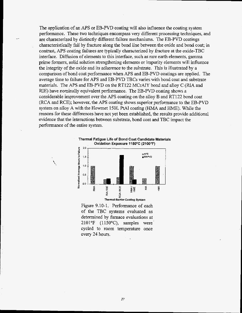
The application of an APS or EB-PVD coating will also influence the coating system performance. These two techniques encompass very different processing techniques, and are characterized by distinctly different failure mechanisms. The EB-PVD coatings characteristically fail by fracture along the bond line between the oxide and bond coat; in contrast, APS coating failures are typically characterized by fracture at the oxide-TBC interface. Diffusion of elements to this interface, such as rare earth elements, gamma prime formers, solid solution strengthening elements or impurity elements will influence the integrity of the oxide and its adherence to the substrate. This is illustrated by a comparison of bond coat performance when APS and EB-PVD coatings are applied. The average time to failure for A P S and EB-PVD TBCs varies with bond coat and substrate materials. The APS and EB-PVD on the RT122 MCrAlY bond and alloy C (RIA and NE) have nominally equivalent performance. The EB-PVD coating shows a considerable improvement over the APS coating on the alloy B and RT122 bond coat (RCA and RCE); however, the A P S coating shows superior performance to the EB-PVD system on alloy A with the Howmet 150L PtAl coating (HMA and HME). While the reasons for these differences have not yet been established, the results provide additional evidence that the interactions between substrate, bond coat and TBC impact the performance of the entire system.
Thermal Fatigue Life of Bond Coat Candidate Materials Oxidation Exposure 1150°C (2100°F)
g 2.0 ,
0 - a a E $u I z B 5 F I?
z < ut
9 5 LT Df
Thermal Barrier Coating System
Figure 9.10-1. Performance of each of the TBC systems evaluated as determined by furnace evaluations at 2101°F (1 150°C), samples were cycled to room temperature once every 24 hours.
27
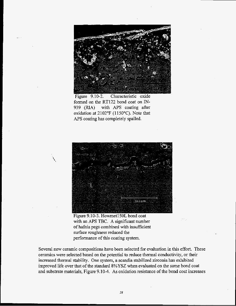
Figure 9.10-2. Characteristic oxide formed on the RT122 bond coat on IN- 939 (RIA) with APS coating after oxidation at 21 02°F (1 150°C). Note that APS coating has completely spalled.
Figure 9.10-3. HowmetlSOL bond coat with an APS TBC. A significant number of hafnia pegs combined with insufficient surface roughness reduced the performance of this coating system.
Several new ceramic compositions have been selected for evaluation in this effort. These ceramics were selected based on the potential to reduce thermal conductivity, or their increased thermal stability. One system, a scandia stabilized zirconia has exhibited improved life over that of the standard 8%YSZ when evaluated on the same bond coat and substrate materials, Figure 9.10-4. As oxidation resistance of the bond coat increases
28
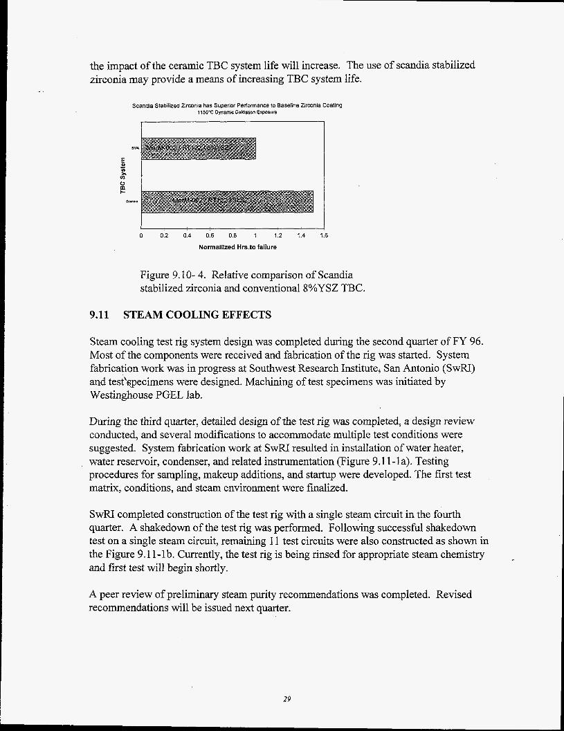
the impact of the ceramic TBC system life will increase. The use of scandia stabilized zirconia may provide a means of increasing TBC system life.
- - Scandia Stabilized Zlrwnia has Superior Performance to Baseline Zirconia Coating
115O'C Dynamic Oudation Exposure
I 0 0.2 0.4 0.6 0.8 1 1.2 1.4 1.6
Nonnailized Hrs.to failure
Figure 9.10- 4. Relative comparison of Scandia stabilized zirconia and conventional 8%YSZ TBC.
9.11 STEAM COOLING EFFECTS
Steam cooling test rig system design was completed during the second quarter of FY 96. Most of the components were received and fabrication of the rig was started. System fabrication work was in progress at Southwest Research Institute, San Antonio (SwRI) and test'specimens were designed. Machining of test specimens was initiated by Westinghouse PGEL lab.
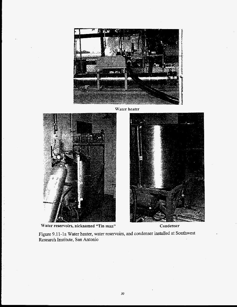
During the third quarter, detailed design of the test rig was completed, a design review conducted, and several modifications to accommodate multiple test conditions were suggested. System fabrication work at SwRI resulted in installation of water heater, water reservoir, condenser, and related instrumentation (Figure 9.1 1 - 1 a). Testing procedures for sampling, makeup additions, and startup were developed. The first test matrix, conditions, and steam environment were finalized.
SwRI completed construction of the test rig with a single steam circuit in the fourth quarter. A shakedown of the test rig was performed. Following successful shakedown test on a single steam circuit, remaining 1 1 test circuits were also constructed as shown in the Figure 9.1 1-lb. Currently, the test rig is being rinsed for appropriate steam chemistry and first test will begin shortly.
-
A peer review of preliminary steam purity recommendations was completed. Revised recommendations will be issued next quarter.
29
Water heater
Water reservoirs, nicknamed 'Tin man" ~ " " " _. - . -
Condenser
Figure 9.1 1-la Water heater, water reservoirs, and condenser installed at Southwest Research Institute, San Antonio
30
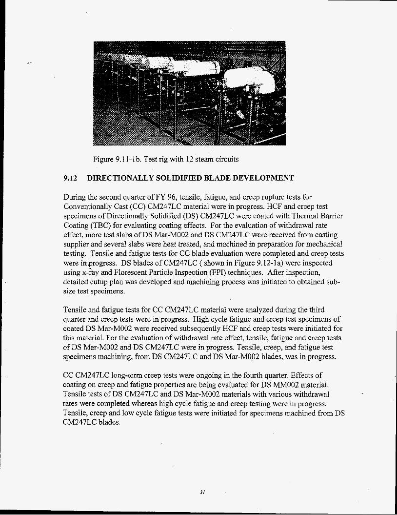
Figure 9.1 1- 1 b. Test rig with 12 steam circuits
9.12 DIRECTIONALLY SOLIDIFIED BLADE DEVELOPMENT
During the second quarter of FY 96, tensile, fatigue, and creep rupture tests for Conventionally Cast (CC) CM247LC material were in progress. HCF and creep test specimens of Directionally Solidified (DS) CM247LC were coated with Thermal Barrier Coating (TBC) for evaluating coating effects. For the evaluation of withdrawal rate effect, more test slabs of DS Mar-MOO2 and DS CM247LC were received from casting supplier and several slabs were heat treated, and machined in preparation for mechanical testing. Tensile and fatigue tests for CC blade evaluation were completed and creep tests were i&?rogress. DS blades of CM247LC ( shown in Figure 9.12-la) were inspected using x-rhy and Florescent Particle Inspection (FPI) techniques. After inspection, detailed cutup plan was developed and machining process was initiated to obtained sub- size test specimens.
Tensile and fatigue tests for CC CM247LC material were analyzed during the third quarter and creep tests were in progress. High cycle fatigue and creep test specimens of coated DS Mar-MOO2 were received subsequently HCF and creep tests were initiated for this material. For the evaluation of withdrawal rate effect, tensile, fatigue and creep tests of DS Mar-MOO2 and DS CM247LC were in progress. Tensile, creep, and fatigue test specimens machining, from DS CM247LC and DS Mar-MOO2 blades, was in progress.
CC CM247LC long-term creep tests were ongoing in the fourth quarter. Effects of coating on creep and fatigue properties are being evaluated for DS MM002 material. Tensile tests of DS CM247LC and DS Mar-MOO2 materials with various withdrawal rates were completed whereas high cycle fatigue and creep testing were in progress. Tensile, creep and low cycle fatigue tests were initiated for specimens machined from DS CM247LC blades.
31
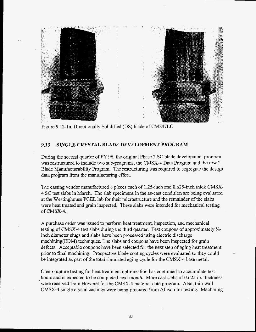
- Figure 9.12-1 a. Directionally Solidified (DS) blade of CM247LC
9.13 SINGLE CRYSTAL BLADE DEVELOPMENT P R O G W
During the second quarter of FY 96, the original Phase 2 SCblade development program was restructured to include two sub-programs, the CMSX-4 Data Program and the row 2 Blade anufacturability Program. The restructuring was required to segregate the design data program from the manufacturing effort. Y The casting vendor manufactured 8 pieces each of 1.25-inch and 0.625-inch thick CMSX- 4 SC test slabs in March. The slab specimens in the as-cast condition are being evaluated at the Westinghouse PGEL lab for their microstructure and the remainder of the slabs were heat treated and grain inspected. These slabs were intended for mechanical testing of CMSX-4.
A purchase order was issued to perform heat treatment, inspection, and mechanical testing of CMSX-4 test slabs during the third quarter. Test coupons of approximately %- inch diameter slugs and slabs have been processed using electric discharge machining(EDM) techniques. The slabs and coupons have been inspected for grain defects. Acceptable coupons have been selected for the next step of aging heat treatment prior to final machining. Prospective blade coating cycles were evaluated so they could be integrated as part of the total simulated aging cycle for the CMSX-4 base metal.
Creep rupture testing for heat treatment optimization has continued to accumulate test hours and is expected to be completed next month. More cast slabs of 0.625 in. thickness were received from Howmet for the CMSX-4 material data program. Also, thin wall CMSX-4 single crystal castings were being procured from Allison for testing. Machining
32
- -
of pin specimens for burner rig oxidation testing has been completed and the test is expected to be started next month.
Solidification modeling at Howmet Whitehall was initiated. 501G R2 wax patters were received and forwarded to Howmet Hampton (foundry). Wax patterns and cores were inspected by Howmet Hampton.
The first two molds were planned to be cast by the end of November and the result will be compared to model predictions.
9.14 ADVANCED VANE ALLOY DEVELOPMENT
During the first quarter of FY 96, thermal analysis s o h a r e was purchased and training received. An alloy database was also purchased and received during December. A subcontract to produce trial castings and conduct weldability testing of the vane alloys was negotiated with Oak Ridge National Laboratory. Steps for subcontract placement began in January.
Baseline mechanical testing on IN-939 has continued. Calculation of the creep equations for IN-939 was completed and provided to design personnel. A Work for Others contract with ORNL was executed on June 3 and submitted to DOE. ORNL will complete small ingot casting and weldability testing. Bead on plate weld tests of IN-939 material and other e erimental compositions were completed. Computer models were constructed for further characterization of the most successful compositions tested. Casting and bead on plate testing on a second set of experimental compositions were planned. Mechanical property testing of these materials will continue.
T?
9.15 BLADE AND VANE LIFE PREDICTION
The blade and vane life prediction program was initiated during the first quarter of FY 96 with the program plan being developed during that period. The program focuses on the life prediction of thermal barrier coated (TBC) and overlay / difision coated components as well.
A number of experiments were designed and partly conducted in FY 96 to generate a database critical for the life prediction models, including
a) stress-relaxation testing of bond coat material (designations SRI-5 and C02 1 1) in the as-sprayed and hot isostatically pressed (HIP’ed) condition. This data is critical for calculating the stresses which build up upon cooling in overlay coatings / TBC’s, and which eventually cause cracking / spallation. These experiments have been concluded
33
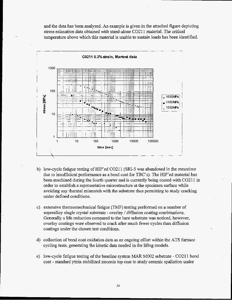
and the data has been analyzed. An example is given in the attached figure depicting stress-relaxation data obtained with stand-alone C02 1 1 material. The critical temperature above which this material is unable to sustain loads has been identified.
- m Y 4 to
2 m
to
C
1000
100
10
1
C0211 0.3% strain, Martest data
1 10 100 1000 10000 100000
time [sec]
I
b) low-cycle fatigue testing of KIP’ed C0211 (Sa-5 was abandoned in the meantime due to insufficient performance as a bond coat for TBC’s). The HIP’ed material has been machined during the fourth quarter and is currently being coated with C0211 in order to establish a representative microstructure at the specimen surface while avoiding any thermal mismatch with the substrate thus permitting to study cracking under defined conditions.
c) extensive thermomechanical fatigue (TMF) testing performed on a number of superalloy single crystal substrate - overlay / diffusion coating combinations. Generally a life reduction compared to the bare substrate was noticed, however, overlay coatings were observed to crack after much fewer cycles than diffusion coatings under the chosen test conditions.
d) collection of bond coat oxidation data as an ongoing effort within the ATS furnace cycling tests, generating the kinetic data needed in the lifing models.
e) low-cycle fatigue testing of the baseline system MAR MOO2 substrate - C0211 bond coat - standard yttria stabilized zirconia top coat to study ceramic spallation under
34
monotonic / cyclic loading conditions at room and elevated temperatures, emulating to some degree the engine environment. The substrate material has been sent out for machining during the fourth quarter. - -
, Regarding the modeling aspects, the following progress has been made :
a) overlay / diffusion coatings it was recognized that the key to understanding the cracking patterns lies in the strain experienced by the coating and not in the mechanical strain imposed on the specimen / component
b) life modeling of electron beam vapor deposited ceramics the stepped bar test as originally developed to discriminate between the HOST I1 model and Concentric Cylinder Model (CCM) proved inconclusive due to significant transient stresses induced during the applied cooling scheme. In the meantime a new approach has been taken by RR, and the CCM has been discarded.
c) life modeling of air plasma sprayed ceramics the HOST I report has been analyzed, and the WALKER code required to model the inelastic behavior of the ceramic has been received. Together with the oxidation and thermal cycle data the HOST I code is ready to be implemented.
9.16 NICKEL-BASED ALLOY ROTOR
The objective of this program is to develop and qualify a supplier of high temperature IN706 discs for combustion turbine applications.
IN706 disc material obtained from vendor A was machined into test specimens for tensile, creep, high cycle fatigue, low cycle fatigue, crack growth, and fracture toughness testing. Tensile testing was completed in the second quarter of FY96 and the data published. The tensile properties obtained were comparable to those published in the outside literature.
Creep testing revealed a notch sensitivity of this IN706 material which had received a two step heat treatment at the vendor’s foundry. A program has been set up to further evaluate the notch sensitivity of this alloy. Creep specimens were examined metallographically and with the scanning electron microscope at PGBU, STC and INCO. These examinations confirmed the initial notch sensitivity results. A plan to test IN706 material which has received a three step heat treatment was initiated with Wyman Gordon. The three step heat treatment is reported as being not notch sensitive in the open literature.
High cycle and low cycle fatigue testing of the ALCOA IN706 material was completed in the third quarter of FY96. These results are currently being published. Crack growth and fracture toughness specimens are currently in test. .
35
- -
Compressor disc forgings for the ATS test compressor were manufactured and were received at Westinghouse in the third quarter. A plan for testing of a qualification disc was issued and specimen machining was begun in the fourth quarter. Creep testing to evaluate the notch sensitivity of the disc forging material, which also received the two step heat treatment, is scheduled for the first quarter of 1997. Other mechanical property tests fiom this material include tensile, high and low cycle fatigue, crack growth and fracture toughness specimens.
Discussions were initiated with ALLVAC as to the feasibility of manufacturing future discs out of IN7 1 8 alloy material. IN71 8 does not appear to exhibit notch sensitivity in creep and has been used extensively for over 30 years in aircraft engine applications. ALLVAC has indicated that they have been successful in producing IN71 8 ingots without alloy segregation in sizes needed for Westinghouse compressor disc forgings.
Ultrasonic test calibration blocks were machined fiom the ALCOA IN706 disc material. An ultrasonic testing process was developed and approved.
11.0 PROGRAM MANAGEMENT
The first quarter review meeting was held January 18 and 19,1996 in Morgantown.
The second quarter review meeting was held April 25 and 26, 1996 in Orlando. \
The thira quarter review meeting was held July 30 and 3 1, 1996 in Morgantown.
Les Southall Program Manager
36