Embed Size (px)
Citation preview
RADIOENGINEERING, VOL. 12, NO. 4, DECEMBER 2003 31
Utilization of MATLAB for Digital Image Transmission Simulation Using the DVB Error Correction Codes
Tomáš KRATOCHVÍL
Department of Radio Electronics, Brno University of Technology, Purkyňova 118, 612 00 Brno, Czech Republic
Abstract. The paper deals with the utilization of Matlab for simulation and analysis of the digital image transmis-sion and transmission distortions in DTV (Digital Televi-sion) and DVB (Digital Video Broadcasting) area. The simulation model that covers selected phenomena of DVB standard baseband signal processing applied in Matlab is presented and features of the protection against transmis-sion errors are outlined. The practical results of FEC (Forward Error Correction) codes efficiency are presented and at the end the GUI application for experimental simu-lation and education is outlined with a simulation example.
Keywords Digital image, forward error correction, transmission channel model, simulation, digital television, DVB.
1. Introduction The DVB in European area deals with the DVB stan-
dard and becomes very popular in the Czech Republic be-cause of the transition conception to digital broadcasting of television and radio services. The satellite service DVB-S of the Czech packet Czechlink is available from satellite Eurobird 1 (GEO 28,5o E) and terrestrial service DVB-T is available around the capital Prague by two experimental pilot projects (Czech Radiocommunications, Czech Digital Group). The digital television starts and it is important to deal with DVB in research and practical education at the technical universities.
2. Approach to Simulation and Analysis of Transmission The project “Simulation and analysis of the digital
signal transmission and transmission distortions in DTV and DVB area” aims are simulation and analysis of the digital signal transmission that corresponds to DVB stan-dards. The transmitted digital signal presents the image data information that is source, channel and link coded, digital modulated and transferred by the digital channel model with variable parameters. One project solution task is creation of the experimental simulation model and its
application in Matlab. The next paragraphs present selected phenomena of DVB signal processing and at the end of the paper is presented the Matlab application features with one simulation example.
RGB to YC C conversion
Image samples multiplexing
FEC coding + interleaving
Protected digital signal
Model of transmission channel(in baseband)
Received digital signal
FEC decoding | deinterleaving
Image samples demultiplexing
YC C to RGB conversionB R
B R
Subjectivecheck of the
transmissionquality
Objectivecheck of thetransmissionquality
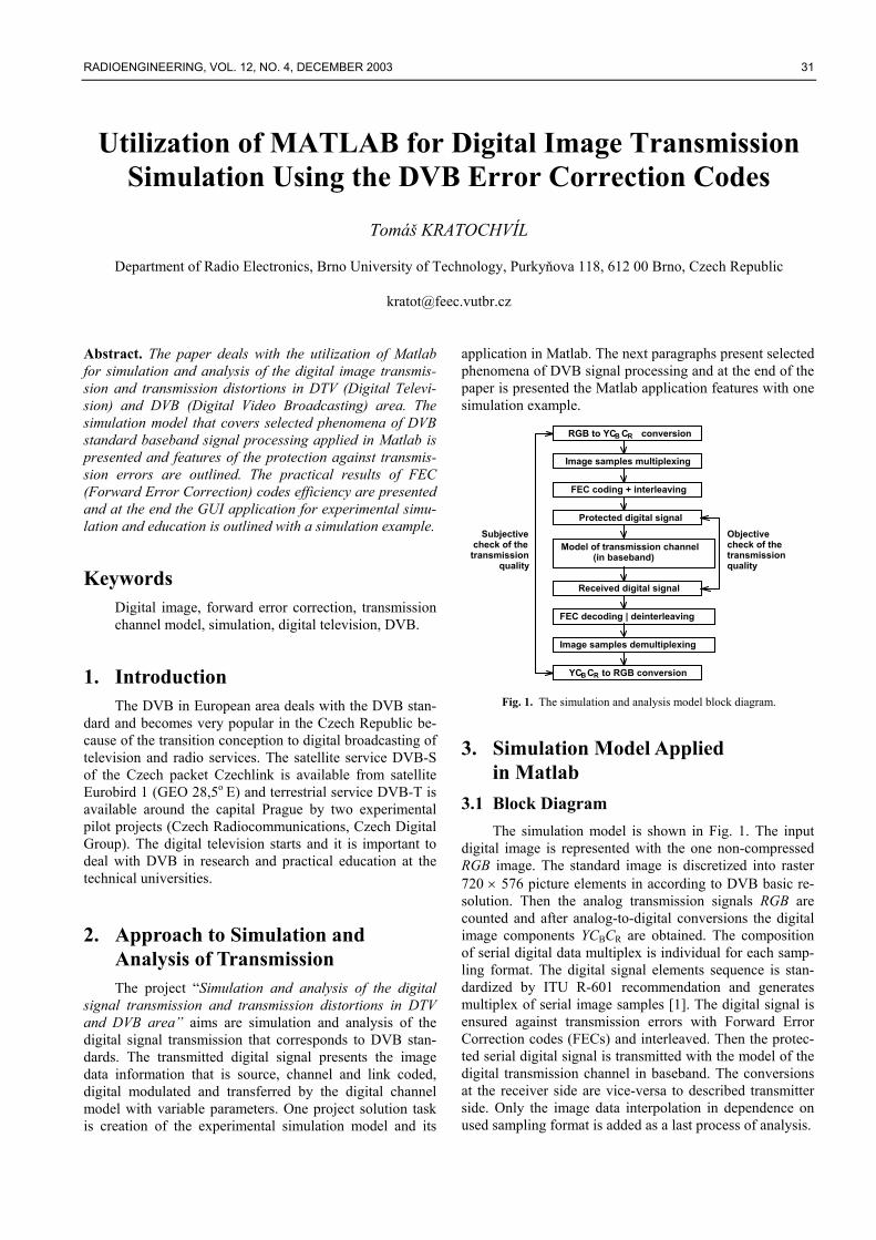
Fig. 1. The simulation and analysis model block diagram.
3. Simulation Model Applied in Matlab
3.1 Block Diagram The simulation model is shown in Fig. 1. The input
digital image is represented with the one non-compressed RGB image. The standard image is discretized into raster 720 × 576 picture elements in according to DVB basic re-solution. Then the analog transmission signals RGB are counted and after analog-to-digital conversions the digital image components YCBCR are obtained. The composition of serial digital data multiplex is individual for each samp-ling format. The digital signal elements sequence is stan-dardized by ITU R-601 recommendation and generates multiplex of serial image samples [1]. The digital signal is ensured against transmission errors with Forward Error Correction codes (FECs) and interleaved. Then the protec-ted serial digital signal is transmitted with the model of the digital transmission channel in baseband. The conversions at the receiver side are vice-versa to described transmitter side. Only the image data interpolation in dependence on used sampling format is added as a last process of analysis.
32 T. KRATOCHVÍL, UTILIZATION OF MATLAB FOR DIGITAL IMAGE TRANSMISSION SIMULATION…
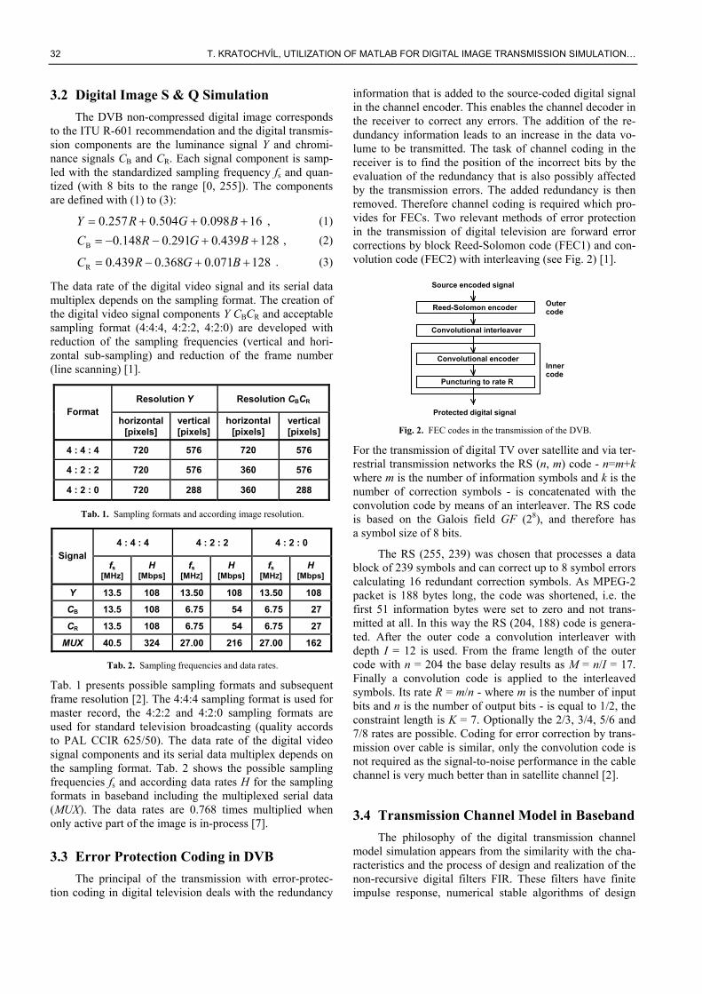
3.2 Digital Image S & Q Simulation The DVB non-compressed digital image corresponds
to the ITU R-601 recommendation and the digital transmis-sion components are the luminance signal Y and chromi-nance signals CB and CR. Each signal component is samp-led with the standardized sampling frequency fs and quan-tized (with 8 bits to the range [0, 255]). The components are defined with (1) to (3):
16098.0504.0257.0 +++= BGRY , (1)
128439.0291.0148.0B ++−−= BGRC , (2)
128071.0368.0439.0R ++−= BGRC . (3)
The data rate of the digital video signal and its serial data multiplex depends on the sampling format. The creation of the digital video signal components Y CBCR and acceptable sampling format (4:4:4, 4:2:2, 4:2:0) are developed with reduction of the sampling frequencies (vertical and hori-zontal sub-sampling) and reduction of the frame number (line scanning) [1].
Resolution Y Resolution CBCR Format
horizontal [pixels]
vertical [pixels]
horizontal [pixels]
vertical [pixels]
4 : 4 : 4 720 576 720 576
4 : 2 : 2 720 576 360 576
4 : 2 : 0 720 288 360 288
Tab. 1. Sampling formats and according image resolution.
4 : 4 : 4 4 : 2 : 2 4 : 2 : 0 Signal
fs [MHz]
H [Mbps]
fs [MHZ]
H [Mbps]
fs [MHZ]
H [Mbps]
Y 13.5 108 13.50 108 13.50 108
CB 13.5 108 6.75 54 6.75 27
CR 13.5 108 6.75 54 6.75 27
MUX 40.5 324 27.00 216 27.00 162
Tab. 2. Sampling frequencies and data rates.
Tab. 1 presents possible sampling formats and subsequent frame resolution [2]. The 4:4:4 sampling format is used for master record, the 4:2:2 and 4:2:0 sampling formats are used for standard television broadcasting (quality accords to PAL CCIR 625/50). The data rate of the digital video signal components and its serial data multiplex depends on the sampling format. Tab. 2 shows the possible sampling frequencies fs and according data rates H for the sampling formats in baseband including the multiplexed serial data (MUX). The data rates are 0.768 times multiplied when only active part of the image is in-process [7].
3.3 Error Protection Coding in DVB The principal of the transmission with error-protec-
tion coding in digital television deals with the redundancy
information that is added to the source-coded digital signal in the channel encoder. This enables the channel decoder in the receiver to correct any errors. The addition of the re-dundancy information leads to an increase in the data vo-lume to be transmitted. The task of channel coding in the receiver is to find the position of the incorrect bits by the evaluation of the redundancy that is also possibly affected by the transmission errors. The added redundancy is then removed. Therefore channel coding is required which pro-vides for FECs. Two relevant methods of error protection in the transmission of digital television are forward error corrections by block Reed-Solomon code (FEC1) and con-volution code (FEC2) with interleaving (see Fig. 2) [1].
Source encoded signal
Reed-Solomon encoder
Convolutional interleaver
Convolutional encoder
Puncturing to rate R
Outer
Protected digital signal
code
Innercode
Fig. 2. FEC codes in the transmission of the DVB.
For the transmission of digital TV over satellite and via ter-restrial transmission networks the RS (n, m) code - n=m+k where m is the number of information symbols and k is the number of correction symbols - is concatenated with the convolution code by means of an interleaver. The RS code is based on the Galois field GF (28), and therefore has a symbol size of 8 bits.
The RS (255, 239) was chosen that processes a data block of 239 symbols and can correct up to 8 symbol errors calculating 16 redundant correction symbols. As MPEG-2 packet is 188 bytes long, the code was shortened, i.e. the first 51 information bytes were set to zero and not trans-mitted at all. In this way the RS (204, 188) code is genera-ted. After the outer code a convolution interleaver with depth I = 12 is used. From the frame length of the outer code with n = 204 the base delay results as M = n/I = 17. Finally a convolution code is applied to the interleaved symbols. Its rate R = m/n - where m is the number of input bits and n is the number of output bits - is equal to 1/2, the constraint length is K = 7. Optionally the 2/3, 3/4, 5/6 and 7/8 rates are possible. Coding for error correction by trans-mission over cable is similar, only the convolution code is not required as the signal-to-noise performance in the cable channel is very much better than in satellite channel [2].
3.4 Transmission Channel Model in Baseband The philosophy of the digital transmission channel
model simulation appears from the similarity with the cha-racteristics and the process of design and realization of the non-recursive digital filters FIR. These filters have finite impulse response, numerical stable algorithms of design
RADIOENGINEERING, VOL. 12, NO. 4, DECEMBER 2003 33
and relatively easy hardware implementation on Digital Signal Processor (DSP) platform. Another advantage of these filters is the linear phase characteristic in mentioned frequency band that is important especially for digital com-ponents signal transmission in digital television [3].
One-dimensional non-recursive filters FIR with finite impulse response have transmission function of the comp-lex variable z (for z = e jωT) described with (4)
∑∑=
−
=
− ⋅=⋅=N
n
nN
n
n znhznazH00
)()()( , (4)
where coefficients a(n), n = 0, 1, 2 , ... , N correspond to coefficients of the impulse characteristic (impulse respon-se) of the filter h(n) and T is a period of sampling. FIR fil-ters can be designed in such a way that they can have exac-tly linear phase characteristics. With this the impulse res-ponse has even or odd symmetry of impulse response and h(n) means non-zero elements of the impulse response h(k). For a low-pass filtering it is interesting the odd symmetry with the even number N+1 of impulse response elements. Frequency characteristic of the FIR filter with linear phase with odd number of the sections of the filter is then (after the conversion to the standardized frequency Ω =ωT, -π ≤ Ω ≤ π) equals to (5) and (6)
)(2
jexp)j( 1 ΩHΩNΩH ⋅
−= , where (5)
∑−
=
−⋅+
=
12
01 2
cos)(22
)(
N
n
ΩnNnhNhΩH . (6)
Equations (5) and (6) are valid for linear phase frequency characteristic of the low-pass filter and the system has the propagation delay tPD equals to half of the impulse respon-se length.
The conventional model [6] for digital baseband transmission channel simulation is the FIR filter with low-pass character and variable parameters and method of de-sign. The design of the proposed digital transmission chan-nel model deals with the input parameters of the channel in according to choose design method. The acceptable design methods for simulation in Matlab are the weighting of the impulse response method, sampling of the frequency cha-racteristic method and design by approximation of frequen-cy characteristic with LS algorithm. These methods give stable results and ensure successful implementation.
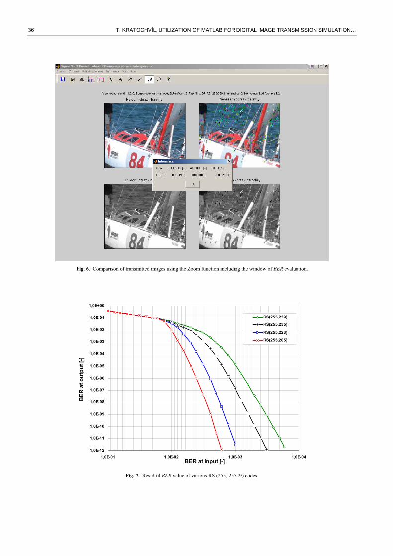
The developed model [7] can change the character of the filter (low-pass, high-pass, band-pass, band-stop, multi-band), possibility of design method selection and it has va-riable parameters (filter order, cut-off frequencies, attenu-ations and allowed ripples of transmission module in pass-band and stopband, interactive design using the tolerant field of the digital transmission channel model). The per-turbative signal and its influence on the transmitted digital signal are developed in all parts of transmission system. The substitution with one source of perturbation signal is
simplification of this idea. This source is usually added to useful signal - additive pertubation and may be modelled for e.g. as the white noise with normal distribution. The next example of pertubative signal is the reflected signal and its influence on the transmitted digital signal.
4. Developed Simulation Application The developed Matlab application (see Fig. 3) [4] [5]
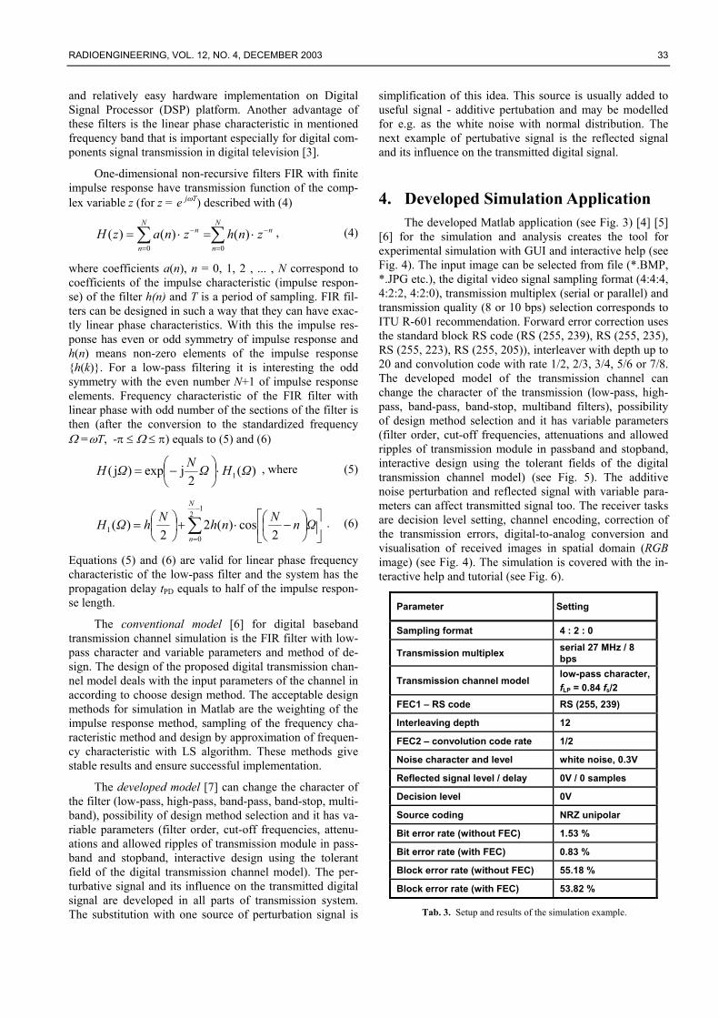
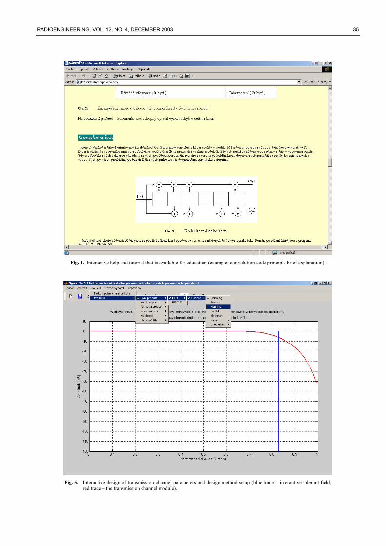
[6] for the simulation and analysis creates the tool for experimental simulation with GUI and interactive help (see Fig. 4). The input image can be selected from file (*.BMP, *.JPG etc.), the digital video signal sampling format (4:4:4, 4:2:2, 4:2:0), transmission multiplex (serial or parallel) and transmission quality (8 or 10 bps) selection corresponds to ITU R-601 recommendation. Forward error correction uses the standard block RS code (RS (255, 239), RS (255, 235), RS (255, 223), RS (255, 205)), interleaver with depth up to 20 and convolution code with rate 1/2, 2/3, 3/4, 5/6 or 7/8. The developed model of the transmission channel can change the character of the transmission (low-pass, high-pass, band-pass, band-stop, multiband filters), possibility of design method selection and it has variable parameters (filter order, cut-off frequencies, attenuations and allowed ripples of transmission module in passband and stopband, interactive design using the tolerant fields of the digital transmission channel model) (see Fig. 5). The additive noise perturbation and reflected signal with variable para-meters can affect transmitted signal too. The receiver tasks are decision level setting, channel encoding, correction of the transmission errors, digital-to-analog conversion and visualisation of received images in spatial domain (RGB image) (see Fig. 4). The simulation is covered with the in-teractive help and tutorial (see Fig. 6).
Parameter Setting
Sampling format 4 : 2 : 0
Transmission multiplex serial 27 MHz / 8 bps
Transmission channel model low-pass character, fLP = 0.84 fs/2
FEC1 – RS code RS (255, 239)
Interleaving depth 12
FEC2 – convolution code rate 1/2
Noise character and level white noise, 0.3V
Reflected signal level / delay 0V / 0 samples
Decision level 0V
Source coding NRZ unipolar
Bit error rate (without FEC) 1.53 %
Bit error rate (with FEC) 0.83 %
Block error rate (without FEC) 55.18 %
Block error rate (with FEC) 53.82 %
Tab. 3. Setup and results of the simulation example.
34 T. KRATOCHVÍL, UTILIZATION OF MATLAB FOR DIGITAL IMAGE TRANSMISSION SIMULATION…
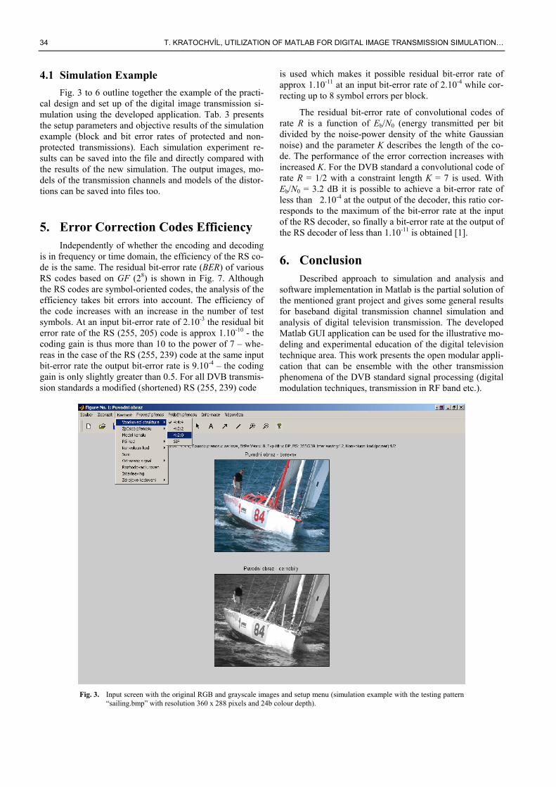
4.1 Simulation Example Fig. 3 to 6 outline together the example of the practi-
cal design and set up of the digital image transmission si-mulation using the developed application. Tab. 3 presents the setup parameters and objective results of the simulation example (block and bit error rates of protected and non-protected transmissions). Each simulation experiment re-sults can be saved into the file and directly compared with the results of the new simulation. The output images, mo-dels of the transmission channels and models of the distor-tions can be saved into files too.
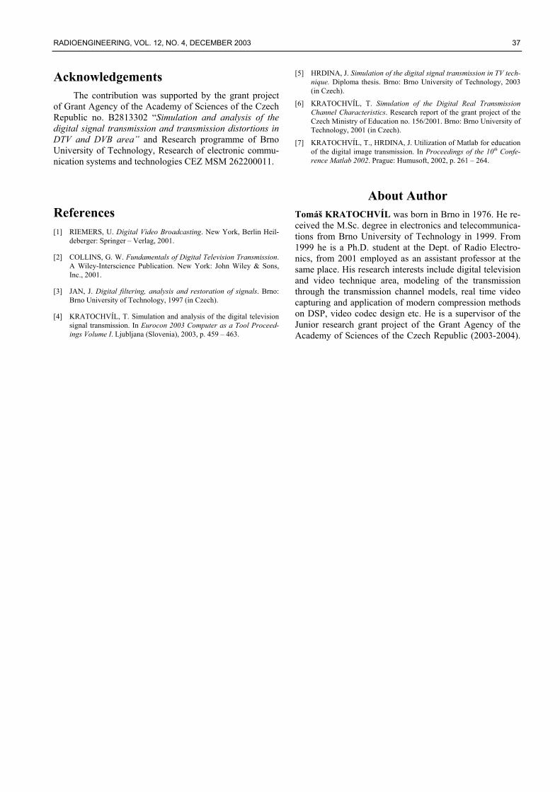
5. Error Correction Codes Efficiency Independently of whether the encoding and decoding
is in frequency or time domain, the efficiency of the RS co-de is the same. The residual bit-error rate (BER) of various RS codes based on GF (28) is shown in Fig. 7. Although the RS codes are symbol-oriented codes, the analysis of the efficiency takes bit errors into account. The efficiency of the code increases with an increase in the number of test symbols. At an input bit-error rate of 2.10-3 the residual bit error rate of the RS (255, 205) code is approx 1.10-10 - the coding gain is thus more than 10 to the power of 7 – whe-reas in the case of the RS (255, 239) code at the same input bit-error rate the output bit-error rate is 9.10-4 – the coding gain is only slightly greater than 0.5. For all DVB transmis-sion standards a modified (shortened) RS (255, 239) code
is used which makes it possible residual bit-error rate of approx 1.10-11 at an input bit-error rate of 2.10-4 while cor-recting up to 8 symbol errors per block.
The residual bit-error rate of convolutional codes of rate R is a function of Eb/N0 (energy transmitted per bit divided by the noise-power density of the white Gaussian noise) and the parameter K describes the length of the co-de. The performance of the error correction increases with increased K. For the DVB standard a convolutional code of rate R = 1/2 with a constraint length K = 7 is used. With Eb/N0 = 3.2 dB it is possible to achieve a bit-error rate of less than 2.10-4 at the output of the decoder, this ratio cor-responds to the maximum of the bit-error rate at the input of the RS decoder, so finally a bit-error rate at the output of the RS decoder of less than 1.10-11 is obtained [1].
6. Conclusion Described approach to simulation and analysis and
software implementation in Matlab is the partial solution of the mentioned grant project and gives some general results for baseband digital transmission channel simulation and analysis of digital television transmission. The developed Matlab GUI application can be used for the illustrative mo-deling and experimental education of the digital television technique area. This work presents the open modular appli-cation that can be ensemble with the other transmission phenomena of the DVB standard signal processing (digital modulation techniques, transmission in RF band etc.).
Fig. 3. Input screen with the original RGB and grayscale images and setup menu (simulation example with the testing pattern
“sailing.bmp” with resolution 360 x 288 pixels and 24b colour depth).
RADIOENGINEERING, VOL. 12, NO. 4, DECEMBER 2003 35
Fig. 4. Interactive help and tutorial that is available for education (example: convolution code principle brief explanation).
Fig. 5. Interactive design of transmission channel parameters and design method setup (blue trace – interactive tolerant field,
red trace – the transmission channel module).
36 T. KRATOCHVÍL, UTILIZATION OF MATLAB FOR DIGITAL IMAGE TRANSMISSION SIMULATION…
Fig. 6. Comparison of transmitted images using the Zoom function including the window of BER evaluation.
1,0E-12
1,0E-11
1,0E-10
1,0E-09
1,0E-08
1,0E-07
1,0E-06
1,0E-05
1,0E-04
1,0E-03
1,0E-02
1,0E-01
1,0E+00
1,0E-041,0E-031,0E-021,0E-01BER at input [-]
BE
R a
t out
put [
-]
RS(255,239)
RS(255,235)
RS(255,223)
RS(255,205)
Fig. 7. Residual BER value of various RS (255, 255-2t) codes.
RADIOENGINEERING, VOL. 12, NO. 4, DECEMBER 2003 37
Acknowledgements The contribution was supported by the grant project
of Grant Agency of the Academy of Sciences of the Czech Republic no. B2813302 “Simulation and analysis of the digital signal transmission and transmission distortions in DTV and DVB area” and Research programme of Brno University of Technology, Research of electronic commu-nication systems and technologies CEZ MSM 262200011.
References [1] RIEMERS, U. Digital Video Broadcasting. New York, Berlin Heil-
deberger: Springer – Verlag, 2001.
[2] COLLINS, G. W. Fundamentals of Digital Television Transmission. A Wiley-Interscience Publication. New York: John Wiley & Sons, Inc., 2001.
[3] JAN, J. Digital filtering, analysis and restoration of signals. Brno: Brno University of Technology, 1997 (in Czech).
[4] KRATOCHVÍL, T. Simulation and analysis of the digital television signal transmission. In Eurocon 2003 Computer as a Tool Proceed-ings Volume I. Ljubljana (Slovenia), 2003, p. 459 – 463.
[5] HRDINA, J. Simulation of the digital signal transmission in TV tech-nique. Diploma thesis. Brno: Brno University of Technology, 2003 (in Czech).
[6] KRATOCHVÍL, T. Simulation of the Digital Real Transmission Channel Characteristics. Research report of the grant project of the Czech Ministry of Education no. 156/2001. Brno: Brno University of Technology, 2001 (in Czech).
[7] KRATOCHVÍL, T., HRDINA, J. Utilization of Matlab for education of the digital image transmission. In Proceedings of the 10th Confe-rence Matlab 2002. Prague: Humusoft, 2002, p. 261 – 264.
About Author Tomáš KRATOCHVÍL was born in Brno in 1976. He re-ceived the M.Sc. degree in electronics and telecommunica-tions from Brno University of Technology in 1999. From 1999 he is a Ph.D. student at the Dept. of Radio Electro-nics, from 2001 employed as an assistant professor at the same place. His research interests include digital television and video technique area, modeling of the transmission through the transmission channel models, real time video capturing and application of modern compression methods on DSP, video codec design etc. He is a supervisor of the Junior research grant project of the Grant Agency of the Academy of Sciences of the Czech Republic (2003-2004).