Embed Size (px)
Citation preview
ELSEVIER Mathematics and Computers in Simulation 38 (1995) 303-310
MATHEMATICS AND
COMPUTERS 7- IN SIMULATION
Utilization of real-time models for the survey and maintenance of high power electrotechnical systems
H. Schne ider a, M. Metz a, H. Piquet a, H. Foch a,*, j . Couraul t b, O. Lapier re b
a Laboratoire d'Electrotechnique et d'Electronique Industrielle, URA n ° 847 du CNRS, Enseeiht-INP, Toulouse, France b Department Entrainements et Electronique de Puissance, Jeumont Industrie, 74430 Champagne/Seine, France
Abstract
This paper illustrates one particular method whereby a real-time model simultaneously operates with an actual Power Electrotechnical System. The principle consists of using the "instantaneous difference" between significant quantities of the actual system and the same quantities simulated in the model.
1. Introduction
Stopping Power Electrotechnical Systems is very costly. For this reason, designers try to find new ways for active, preventive and curative maintenance in order to minimize consequences of the stopping time. The principle of the presented method, consists of using the "instantaneous difference" between significant quantities of the actual system and the same quantities simulated in the model; the simultaneous operation requires a fast model which is implanted on an analog simulator using the CASSIS procedure below described.
When a difference appears, it suggests there is a fault in the actual system. Analysing these differences, which are specific failure signatures, gives information about both the nature and the cause of these failures. Thus a knowledge base may be built and further exploited. This means for example that after a learning process, every failure which may occur on a given system, may be almost immediately identified. This information then allows new control, survey and maintenance strategies to be developed. The difference can also be used to determine and track inaccessible parameters thus allowing the determination of some special regulation loop coefficients. In a general way, the simulator, which is a real-time follower of the actual system, may be considered as an intelligent sensor (estimator) of significant system quantities.
* Corresponding author.
0378-4754/95/$09.50 © 1995 Elsevier Science B.V. All rights reserved SSDI 0378-4754(95)00040-Q
304 H. Schneider et aL / Mathematics and Computers in Simulation 38 (1995) 303-310
"1
LOG~
I 1 ~ 1 ~ 1 ~ ; I Circuit
K v -- of tgq Interface
G
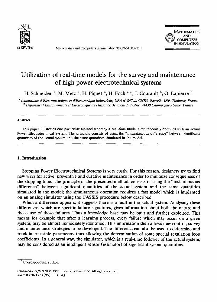
Fig. 1. G T O model.
In other respects, owing to its simultaneous operation, the simulator may be used to validate new control laws just before starting the system.
The following text describes the simulator, explains the method principles and illustrates some of its potential with experimental examples.
2. Simulator principle
The CASSIS simulator is composed of independant electronic circuits which simulate power switches, inductors, capacitors and electrical machines. Physical external connections allow these elements to be connected together as for actual systems. As for a classical analog computer, all the quantities are represented by voltages (whose magnitude are less than or equal to 10V).
2.1. Switches models (example of the GTO)
Using actual switches like diodes and transistors is not satisfactory because of the large voltage drop during the 'on' state, with respect to simulator voltages; hence they are made up using a FET, a comparator and logic circuits, representing the functionnal properties of any given switch as shown in Fig. 1. Furthermore, the inherent speed of the analog operators allows phenomena such as turn-off delays (for example tgq for a GTO), to be taken into account. This is possible by means of a small analog calculation unit, set in parallel with the base structure of the switch, as shown on Fig. 1.
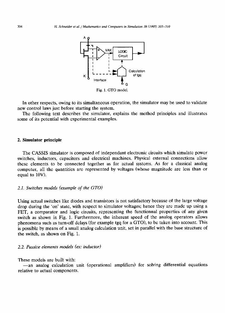
2.2. Passive elements models (ex: inductor)
These models are built with: - - a n analog calculation unit (operational
relative to actual components. amplifiers) for solving differential equations
H. Schneider et aL / Mathematics and Computers in Simulation 38 (1995) 303-310 305
r- ~ I I-N!E-RF-A"CE"
: 2 4 / ' - - 1 + \ '
: TI / /
Analog Voltage/ Voltage/ Calculation current Voltage Unit
Fig. 2. Inductor model.
- - a specific interface circuit for changing the voltage-voltage analog unit into an actual dipole (A, B terminals) as shown in Fig. 2.
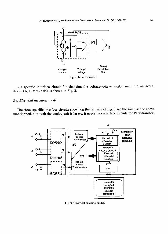
2.3. Electrical machines models
The three specific interface circuits shown on the left side of Fig. 3 are the same as the above mentionned, although the analog unit is larger: it needs two interface circuits for Park-transfor-
V1
V2
V3
P ~ m
( ~ - - - = i
~'F~C'E F - - - T
i2 I
I~ffF.~C~ I " - - - 1 '
C ~ : ~-4 i3 I I ~
L - - - - - - J INTERFACE
7 L , 4 - -
--I
i
--I
.-I
3 phase/ 2 phase
Transformation
2 phase/ 3 phase
Transformation
Mechanical differential Equation ANALOG
CALCULATION Electrical
differential Equation
Simulation of an
electrical machine
I Computer 1 (assigned differential equation
. coefficients)
Fig. 3. Electrical machine model.
306 H. Schneider et aL / Mathematics and Computers in Simulation 38 (1995) 303-310
POWER SUPPLY 0
I ACTUAL SYSTEM
actual system £ ~difference control
A aota,,on I loop ~ I parameters
Maintenance
J MODEL
Model control
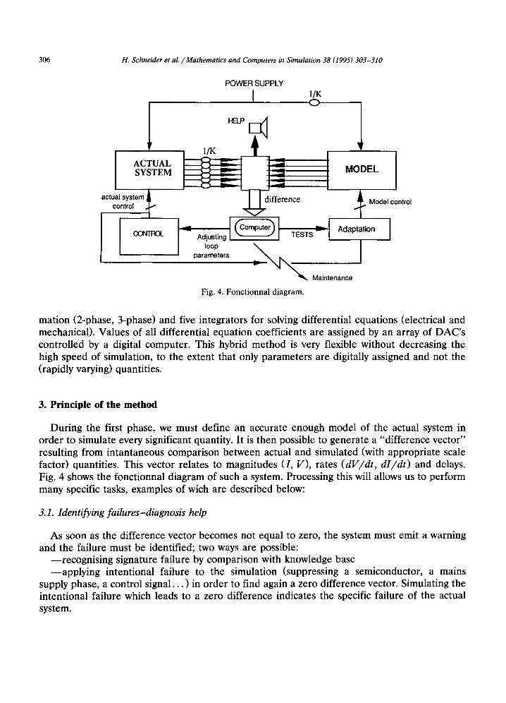
Fig. 4. Fonctionnal diagram.
mation (2-phase, 3-phase) and five integrators for solving differential equations (electrical and mechanical). Values of all differential equation coefficients are assigned by an array of DAC's controlled by a digital computer. This hybrid method is very flexible without decreasing the high speed of simulation, to the extent that only parameters are digitally assigned and not the (rapidly varying) quantities.
3. Principle of the method
During the first phase, we must define an accurate enough model of the actual system in order to simulate every significant quantity. It is then possible to generate a "difference vector" resulting from intantaneous comparison between actual and simulated (with appropriate scale factor) quantities. This vector relates to magnitudes (I, V), rates (dV/dt, dI/dt) and delays. Fig. 4 shows the fonctionnal diagram of such a system. Processing this will allows us to perform many specific tasks, examples of wich are described below:
3.1. Identifying failures-diagnosis help
As soon as the difference vector becomes not equal to zero, the system must emit a warning and the failure must be identified; two ways are possible:
--recognising signature failure by comparison with knowledge base --applying intentional failure to the simulation (suppressing a semiconductor, a mains
supply phase, a control signal. . . ) in order to find again a zero difference vector. Simulating the intentional failure which leads to a zero difference indicates the specific failure of the actual system.
H. Schneider et al. / Mathematics and Computers in Simulation 38 (1995) 303-310 307
3.2. Identifying and monitoring parameters
A difference vector may arise when actual system parameters value differ from that of simulated ones (taking into account scale factor); by modifying the simulated system until the difference becomes zero, it is possible to identify and follow a particular parameter of the actual system, which is generally difficult to do with classical measuring procedures.
Hence, for example, we are able to find the rotor time constant of an induction machine (which varies in a large range) while the system "on line". In the same way we can find the inertia and the dispersion coefficients. From these parameters it would be possible, for example, to adjust the regulation loop parameters.
3.3. Initial "on-line" operation and pre-adjustment
In order to facilitate the initial "on-line" operation, we are able to verify control behaviour using the simulator with actual control signals, and a priori known parameters: those indicated by the rating plate and the inertia presumed for the whole system for example. This allows preadjustment of these signals. Thus with wise adjustments, the first start-up should occur without stressing the motor, the mechanics nor the supply.
4. Utilization perspectives
Many applications in which the motors are fully inaccessible, are likely to arise in the next few years, particularly for undersea oilfield exploitation; this kind of application is character- ized by a distance of over 50 kM between the converter and the machine; this makes it impractical to bring send quantities back up to the control: motor current, voltage and speed for example.
By means of a model that takes into account the wire transfer function, we can obtain a controllable image of the machine.
Other applications where breakdowns could be damaging, such as rolling mills, chemical processes . . , must be prevented from failing abruptly; when a failure happens, it is necessary to find a degraded type of operation in order to stop the process under the best conditions (i.e. "fail safe"); then the simulator may be used to test a number of control laws until it finds the one which seems to be the best adapted to a particular type of failure.
5. Experimental examples
Two examples are presented below, wich illustrate the potential of the method from the simulation of part of the system (a power switch) to the simulation of a whole converter.
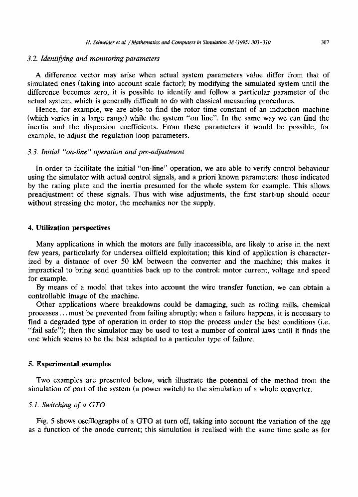
5.1. Switching of a GTO
Fig. 5 shows oscillographs of a GTO at turn off, taking into account the variation of the tgq as a function of the anode current; this simulation is realised with the same time scale as for
308 H. Schneider et al. / Mathematics and Computers in Simulation 38 (1995) 303-310
i . . . . Anode current
il 1 control signal
Fig. 5. Oscillographs of the simulation of a GTO turn off taking into account the tgq delay. [Anode current]: 1V/Div; Time: 40tzs/Div.
the actual GTO; a difference between simulated and actual tgq may indicate an abnormal warming up of the actual switch; this difference allows the junction temperature to be estimated and this estimation is not delayed by the thermal inertia of the package, the hea ts ink . . .
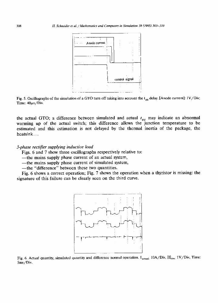
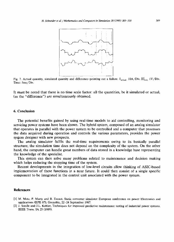
3-phase rectifier supplying inductive load Figs. 6 and 7 show three oscillographs respectively relative to: - - t h e mains supply phase current of an actual system, - - t h e mains supply phase current of simulated system, - - t h e "difference" between these two quantities. Fig. 6 shows a correct operation; Fig. 7 shows the operation when a thyristor is missing: the
signature of this failure can be clearly seen on the third curve.
Fig. 6. Actual quantity, simulated quantity and difference normal operation. Iactual: 10A/Div, [I]sim: 1V/Div, Time: 5ms/Div.
H. Schneider et al. / Mathematics and Computers in Simulation 38 (1995) 303-310 309
Fig. 7. Actual quantity, simulated quantity and difference-pointing out a failure. Iactual: 10A/Div, [I]sim: 1V/Div, Time: 5ms/Div.
It must be noted that there is no time scale factor: all the quantities, be it simulated or actual, (as the "difference") are simultaneously obtained.
6. Conclusion
The potential benefits gained by using real-time models to aid controlling, monitoring and servicing power systems have been shown. The hybrid system, composed of an analog simulator that operates in parallel with the power system to be controlled and a computer that processes the data acquired during operation and controls the various parameters, provides the power sysIem designer with new prospects.
The analog simulator fulfils the real-time requirements owing to its basically parallel structure; the simulation time does not depend on the complexity of the system. On the other hand, the computer can handle great numbers of data stored in a knowledge base representing the knowledge of the specialist.
This system can then solve many problems related to maintenance and decision making which helps reducing the stopping time of the system.
Recent developments in the integration of low-level circuits allow thinking of ASIC-based implementation of these functions in a near future. It could then consist of a single specific component to be integrated in the control unit associated with the power system.
References
[1] M. Metz, P. Marty and B. Escaut, Static converter simulator European conference on power Electronics and applications (EPE 87), Grenoble, 22-24 September 1987.
[2] J. Sottile and J.L. Kohler, Techniques for improved predictive maintenance testing of industrial power systems, IEEE Trans. IA 25 (1989).

310 H. Schneider et al. / Mathematics and Computers in Simulation 38 (1995) 303-310
[3] S. Pinson Representation des connaissances dans les systemes experts, R.A.I.R.O. Informatique Computer Science 15 (1981) 343-367.
[4] M. Metz, Simulation analogique globale des systems ?~ interrupteurs semi-conducteur par interfaces sp6cialis6es (Proc6d6 CASSIS); Caract6risation en r6gime permanent et r6gime transitoire des circuits de commutation forc6e des convertisseurs statiques ~ thyristors, Th6se Deteur 6s-science, Institut National Polytechnique de Toulouse, 1985.
[5] K. Szafnicki, S. Gentil, An object oriented knowledge-based system for process identification, 5th IFAC/IMACS Symposium on CADCS, Swansea (UK), July 1991.