Embed Size (px)
Citation preview

Experimental Study on Effect of Changing Welding Current
on Mechanical and Metallurgical Properties of Seam
Welding Joint for Low Carbon Steel AISI 1005 (0.8 mm)Ammar Azeez Mahdi AL-Yasari
Welding Department - Technical College Baghdad
Abstract
The aim of this work is to study the effect of changing welding current on the
mechanical and metallurgical properties and choose the best welding current depend
on result of study. The present work is an experimental study on effect of changing
welding current on properties of seam welding joint for low carbon steel AISI 1005.
Experiments results shows with increase welding current, hardness number will
increase, also differentness in hardness number between weld nugget and HAZ (Heat
Affected Zone) will increase and border of HAZ become bigger. Best mechanical
results was achieved when welding current increased this doesn't mean that the
highest current will become the suitable one, because the higher current will cause
burin through in metal sheets and will cause leakage in products (liquid or gas storage
tank), also will effect on grain size and microstructure due to changes in cooling rate,
also the final shape of joints its important because most application of this type of
weld is weight-goods industries (for civil using), so when use high welding current
the final shape of joint will deform. Depended on above the best welding current rang
is between 17 ≤ I < 19 K Amp.
Keywords: Mechanical and Metallurgical Properties of weldment,
Seam welding.
الخالصة الميكانيكية الخواص على اللحام تيار تغير تاثير دراسة الى البحث يهدف
, افضل واختيار الكاربون واطىء للحديد المستمر النقطي اللحام لوصالت والميتالورجية
, رقم زاد اللحام تيار زاد كلما انه العملية النتائج اظهرت حيث النتائج على ً معتمدا تيار
اليعني هذا والكن الميكانيكية الخواص تحسنت اي الشد مقاومة وزادة للملحومة الصالدة
مما اللحام مناطق بعض انصهار الى يؤدي قد النه قيمة األعلى هو يستخدم تيار افضل ان
, الخزانات في يكون اللحام من النوع هذا استخدامات اغلب ألن المنتج في العيب يؤدي
يكون لذلك المدنية التطبيقات اغلب في للعيان ظاهرة تكون اللحام هذا تطبيقات ان كما

كما والميكانيكية المجهرية الخواص معطيات على ً وبناءا ضروري للمنتج النهائي الشكل
بين يتراوح لحام تيار باستخدام هي نتائج افضل كانت للحام األمريكية الجمعية 17اوصت
. 19و امبير كيلو
Introduction Seam welding involves the joining of two or more pieces of sheet metal in
localized areas where melting and coalescence of a small volume of material occurs
from heating caused by resistance to the passage of an electric current. A common
example is the gastight or liquid tight [1]. This study tries to choose the best welding
current that improve joint mechanical and metallurgical properties, without deflect its
final shape because some of these joint will be clear to show in the final products.
1- Theoretical partsResistance Seam Welding (RSEW) is a process in which heat caused by
resistance to the flow of electric current in the work metal is combined with pressure
to produce a welded seam. This seam consisting of a series of overlapping spot
welds is normally gastight or liquid tight .Two rotating circular electrodes (electrode
wheels) or one circular and one bar-type electrode are used for transmitting the
current to the work metal . When two electrode wheels are used, one or both wheels
are driven either by means of a gear driven shaft or friction drive that contacts the
peripheral surface of the electrode wheel.
The series of spot welds is made without retracting the electrode wheels or
releasing the electrode force between spots although the electrode wheels may
advance either continuously or intermittently. The magnitude of the current, the
duration of current flow, the electrode force, and the speed of work piece or
electrode travel are all related and must be properly chosen and controlled to
produce a satisfactory resistance seam welded joint. The principles described in the
article “Resistance Spot Welding” (RSW) in this volume are applicable also to
RSEW. [1]
1-2 Seam Welding CycleThe process sequences of seam welding are explaining bellow there are five
definite stages with time:
1- Squeeze time: - The time elapsed between the initial application of the
electrode force on the work piece and first application of current in making
seam weld.
2- Weld time (weld interval):- the time period in which welding current is
applied to the work during making a single-impulse.
3- Heat time:- The time that the current flows during any one impulse .
4- Cool time: - The time interval between successive heat times.
5- Hold time: - The time period during which force is applied to the work after
current ceases to flow.[2]
2- Experimental works: According AWS (American Welding Society) resistance welding hand book there
are three tests should be done to mead sure that the suitable settings are be used there
are[1-3] :
1. Tensile-shear test
2. Micro hardness test
3. Microstructure test
The main steps of the experimental works conducted in this study are;
1- Measuring the mechanical properties and failure mechanism for base metal and
resistance seam weld. This includes:
(a) Measuring the ultimate tensile strength and breaking load for base metal and
resistance seam weld specimens.
(b) Measuring the micro hardness number to determine the limits of HAZ, and the
deference in the hardness number between the base metal and welding zone.
2- Studying the microstructure of all welding zones (base metal, welding nugget and
heat affected zone) to describe nugget size, grain size and arrangement.
The nominal chemical composition and nominal mechanical properties of cold rolled
AISI 1005 low carbon steel sheet (0.8mm) is shown in Table 1 and Table 2,
respectively.
Table (1) Nominal chemical composition of low carbon steel AISI 1005
Material type C% Mn% Si% P% S%

Plain carbon steel 0.09 0.20-0.4 0.017 0.04 0.05
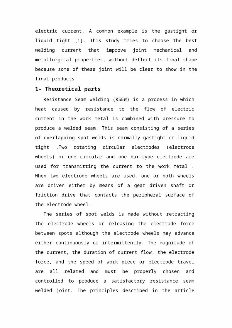
Table (2) Nominal mechanical properties of low carbon steel AISI 1005
Mechanical
properties
Material type
Tensile
strength
(MPa)
Yield
Strength
(MPa)
Modulus of
elasticity
(GPa)
Strain
mm / mmHV
low carbon steel
AISI 1006325 177 200 0.25 119
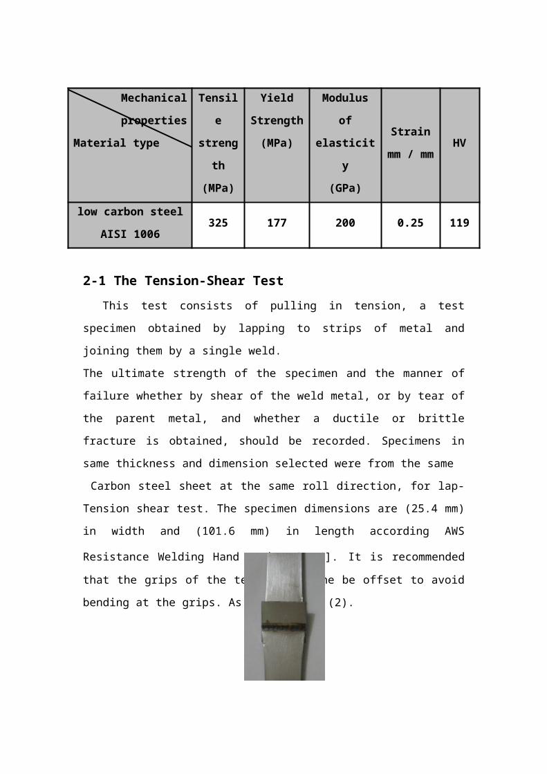
2-1 The Tension-Shear Test This test consists of pulling in tension, a test specimen obtained by lapping to
strips of metal and joining them by a single weld.
The ultimate strength of the specimen and the manner of failure whether by shear of
the weld metal, or by tear of the parent metal, and whether a ductile or brittle fracture
is obtained, should be recorded. Specimens in same thickness and dimension selected
were from the same
Carbon steel sheet at the same roll direction, for lap- Tension shear test. The
specimen dimensions are (25.4 mm) in width and (101.6 mm) in length according
AWS Resistance Welding Hand Book [1] [4]. It is recommended that the grips of the
testing machine be offset to avoid bending at the grips. As show in fig (2).
Fig (2) seam welding joints
2-2 Micro Hardness Test According ISO standard metallic materials hardness test HV1 (1) Kg force load
was applied to surface of specimen to achieve accurate result. Fig (3) shows a sketch
explaining micro hardness locations, results have been taken along straight line

starting at center of seam-weld through HAZ until reaching to unaffected base metal
(results become same), these results have been taken at each 0.5 mm.[3]
Fig (3) sketch show micro hardness line2-3 Microstructure Testing
To show the microstructure changes and grains arrangement, and also to describe
welding zone after welding process was completed, also to find the formed phases in
the weld nugget and heat affected zone, the microstructure test was carried out.
3- Result and discussions
3-1 The Tension-Shear Test resultsFigures (4) through (7) show the load displacement curves as a result of tensile
shear test for different seam welding currents.
Fig, (4) shows load displacement curve for 13 Kamp welded joint, maximum load
was 1830 N with 0.42 mm the fracture take place at welding metal, weld was clean,
full smooth (without any concave or convex), the weldment was free from burn
through and electrodes end dose not effected by welding.
Fig.(5) represented load displacement curve for 15 K Amp, 6000 N was the maximum
load with 23 mm displacement and the tearing by 45◦ happen at the base metal, the
joint was clean less smoothly than the previous one (low concave or convex), the
weldment was free from burn through and electrodes end dose not effected by
welding
Fig (6), shows load displacement curve for 17 K Amp maximum load was 6350 N at
23 mm also the tearing by 45◦ is happen at the base metal, the weld still clean has low
concave and convex, more homogenous and electrodes dose not effect, the weldment
was free from burn through
At (19 Kamp) load reached to(6000 N) with displacement (18mm ) and the tearing by
45◦ is happen at the base metal fig.(7).
3-2 Micro Hardness Test results As explained in a previous chapter on the procedure of test, the measuring starts
from center and along straight line outside nugget. It is obvious that the lowest
hardness number (for welding zone) registered is in nugget center, the number of
hardness gradually increases until it reaches its highest value in HAZ these
differentness in hardness number due to the difference in cooling rate between nugget
and HAZ which mainly affected in grain size. Fig(8), shows all hardness curves of all
welded specimens, by careful look to this curve it’s found: first HAZ width have
direct relation with current increase, second the difference in hardness number
between weld nugget and HAZ increase with increase of welding current this is
normal because the cooling rate will be different in each time, and third all carve meat
at 0.5 mm from center.[4-5]

Fig (8), micro hardness test result3-3 Microstructure Test Results
Figures (9) through (12) show the microstructure for different welding currents
joints, this figure aim to show changes in grain size and arrangement with welding
current. [6]
First look for four microstructure photos its difficult make a distinction among
grain size because there is direct water cooling during welding this made process is
like quenching, but still some differentness, grain size appear somewhat bigger when
welding current raised and became more homogenous specially for 17 K Amp.
Fig (9) microstructure
for 13 K Amp
welded joint
Fig (10) microstructure
for 15 K Amp
welded joint
Fig (11) microstructure
for 17 K Amp
welded joint
Fig (12) microstructure
for 19 K Amp
welded joint

1- Conclusions
1. The best welding current for AISI 1005 (0.8 mm) was 17 Kamp.
2. When welding current increase strength of welded joint increase to, until reach
to 19 Kamp the metal become burn through.
3. The width of HAZ is between 3 to 3.5 mm and the difference between in the
hardness number of weld nugget and HAZ become large when welding current
increase.
No large difference in grains size when using different welding current but still there
is relationships between them grain size appear somewhat bigger when welding
current raised.
2- References
1- Resistance welding theory and use, American Welding Society 1956.
2- Bienvenu, Join “An Investigation of Resistance Welding Performance of
Advanced High-Strength Steels” auto / steel partnership 2000
3- C. L. Tsai, D. W. Dickinson, C. Y. Kim, and M. D. Garnett “Mechanical
Behaviors of Resistance Spot Welds During Pry- checking Test” Welding
Journal, American Welding Society, JUNE 2006
4- M. Zhou,s. J Hu and H. Zhang “Critical Specimen Size for Tensile-Shear
Testing of Steel Sheets”, Welding Research Supplement, 1997
5- W. L. Chuko, and J. E. Gould, “Development of Appropriate Resistance
Welding Practice for Transformation-Hardened Steels” Supplement to
Welding Journal, January, 2002