Embed Size (px)
Citation preview

UTRAN Radio Resource Management
IntroductionHandover Control
Soft/Softer HandoverInter Frequency Handover
Power ControlClosed Loop Power ControlOpen Loop Power Control
Interference Management
Load Control
Call Admission ControlCongestion Control
Packet Data Transmission
Packet Data ControlDynamic Scheduling
BTS 1
BTS 3
BTS 2UE

UMTS Networks 2Andreas Mitschele-Thiel, Jens Mueckenheim Nov. 2011
References
H. Holma, A. Toskala (Ed.), “WCDMA for UMTS”, Wiley, 5th edition, Wiley, 2010Walke, Althoff, Seidenberg: UMTS – Ein Kurs. J. Schlembach Fachverlag, 2002H. Kaaranen, et.al., “UMTS Networks: Architecture, Mobility and Services”,
Wiley, 2001. (see chapter 4)
A. Viterbi: “CDMA: Principles of Spread Spectrum Communications,” Addison Wesley, 1995.
J. Laiho, A. Wacker, T. Novosad (ed.): “Radio Network Planning and Optimisation for UMTS,“ Wiley, 2001
T. Ojanperä, R. Prasad, “Wideband CDMA for Third Generation Mobile Communication”, Artech House, 1998.
R. Prasad, W. Mohr, W. Konhäuser, “Third Generation Mobile Communications Systems”, Artech House, March 2000.
3GPP standards:
TS 25.214: “Physical Layer Procedures“ (esp. power control)TR 25.922: “Radio Resource Management Strategies“TR 25.942: “RF System Scenarios“

UMTS Networks 3Andreas Mitschele-Thiel, Jens Mueckenheim Nov. 2011
Efficient use of limited radio resources (spectrum, power, code space)Minimizing interference Flexibility regarding services (Quality of Service, user behaviour)Simple algorithms requiring small signalling overhead onlyStability and overload protectionSelf adaptive in varying environmentsAllow interoperability in multi-vendor environments
Radio Resource Management algorithms control the efficient use of resources with respect to interdependent objectives:– cell coverage– cell capacity– quality of service
RRM – High-Level Requirements

UMTS Networks 4Andreas Mitschele-Thiel, Jens Mueckenheim Nov. 2011
RRM – Components
Radio Resource Management
MediumAccessControl
Packet DataControl
LoadControl
HandoverControl
PowerControl
Core Network/ other RNCs
Physical layer
typically in RNC
typically in NodeB
UMTS Networks 5Andreas Mitschele-Thiel, Jens Mueckenheim Nov. 2011
Handover Control: Basics
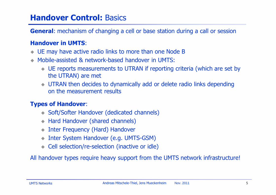
General: mechanism of changing a cell or base station during a call or session
Handover in UMTS:UE may have active radio links to more than one Node BMobile-assisted & network-based handover in UMTS:
UE reports measurements to UTRAN if reporting criteria (which are set by the UTRAN) are metUTRAN then decides to dynamically add or delete radio links depending on the measurement results
Types of Handover:Soft/Softer Handover (dedicated channels)Hard Handover (shared channels)Inter Frequency (Hard) HandoverInter System Handover (e.g. UMTS-GSM)Cell selection/re-selection (inactive or idle)
All handover types require heavy support from the UMTS network infrastructure!

UMTS Networks 6Andreas Mitschele-Thiel, Jens Mueckenheim Nov. 2011
Macro Diversity & Soft Handover (Wrap-Up)
Downlink: combining in the mobile station Uplink: combining in the base station and/or radio network controller
NodeB 1NodeB 2
UE

UMTS Networks 7Andreas Mitschele-Thiel, Jens Mueckenheim Nov. 2011
Soft/ Softer Handover
In soft/softer handover the UE maintains active radio links to more than one Node BCombination of the signals from multiple active radio links is necessary
Soft HandoverThe mobile is connected to (at least) two cells belonging to different NodeBsIn uplink, the signals are combined in the RNC, e.g. by means of selection combining using CRC
Softer HandoverThe mobile is connected to two sectors within one NodeBMore efficient combining in the uplink is possible like maximum ratio combining (MRC) in the NodeB instead of RNC
Note:In uplink no additional signal is transmitted, while in downlink each new link causes interference to other users, therefore:
Uplink: HO general increase performanceDownlink: Trade-off
UMTS Networks 8Andreas Mitschele-Thiel, Jens Mueckenheim Nov. 2011
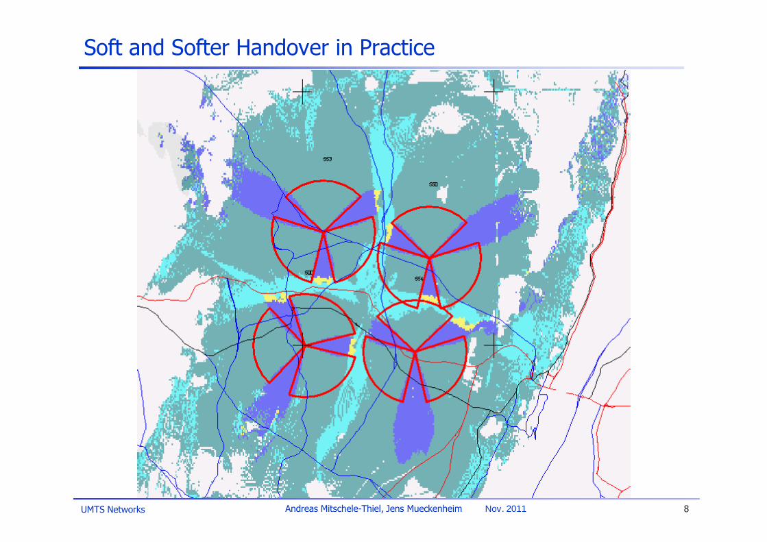
Soft and Softer Handover in Practice
UMTS Networks 9Andreas Mitschele-Thiel, Jens Mueckenheim Nov. 2011
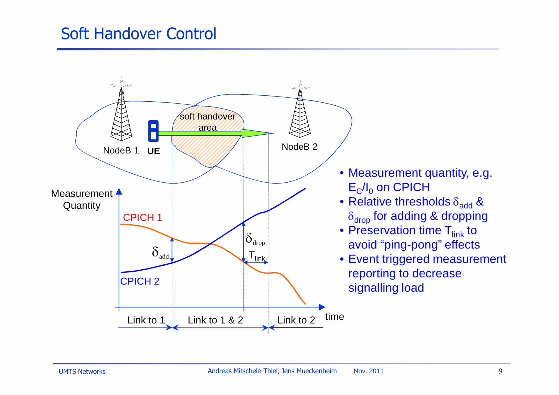
Soft Handover Control
• Measurement quantity, e.g. EC/I0 on CPICH
• Relative thresholds add & drop for adding & dropping
• Preservation time Tlink to avoid “ping-pong” effects
• Event triggered measurement reporting to decrease signalling load
MeasurementQuantity
Link to 1 Link to 1 & 2 Link to 2 time
CPICH 1
CPICH 2
drop
NodeB 1 NodeB 2
add Tlink
UE
soft handoverarea

UMTS Networks 10Andreas Mitschele-Thiel, Jens Mueckenheim Nov. 2011
Soft Handover – Simulation Results
Soft handover significantly improves the performance, but …
0%
5%
10%
15%
20%
25%
5 15 25 35 45 55
Offered Traffic [Erlang per site]
Out
age
Pro
babi
lity
(Blo
ckin
g an
d D
ropp
ing)
1 linkmax 2 SHO linksmax 4 SHO linksmax 6 SHO links

UMTS Networks 11Andreas Mitschele-Thiel, Jens Mueckenheim Nov. 2011
Soft Handover – Simulation Results II
… the overhead due to simultaneous connections becomes higher!
0
0,5
1
1,5
2
1 2 4 6
Max. Active Set Size
Mea
n N
umbe
r of A
ctiv
e Li
nks

UMTS Networks 12Andreas Mitschele-Thiel, Jens Mueckenheim Nov. 2011
Handover f1 f2 always needed between layers
Hierarchical cell structure (HCS)
Macro Micro Macro
f1
f2
f1
Handover f1 f2 needed sometimes at hot spot
Hot-spot
f1
f2f1 f1
Hot spot
Inter-Frequency Handover
Hard handoverInter-frequency measurements of target cell needed in both scenariosMobile-assisted handover (MAHO)
slotted (compressed) mode for inter-frequency measurements to find suitable target cellalso supports GSM system measurements
Database assisted handover (DAHO)no measurements performed on other frequencies or systemsuse cell mapping information stored in data base to identify the target cell
UMTS Networks 13Andreas Mitschele-Thiel, Jens Mueckenheim Nov. 2011
Power Control: Basics
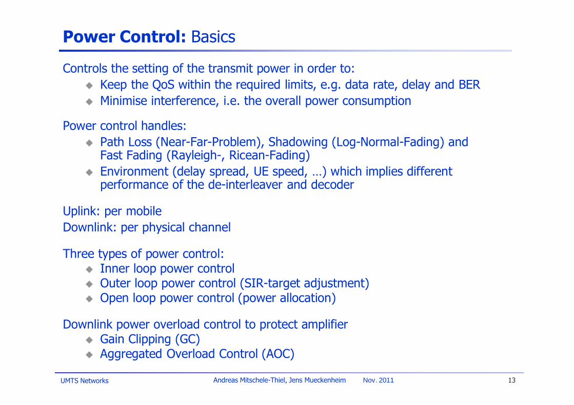
Controls the setting of the transmit power in order to:Keep the QoS within the required limits, e.g. data rate, delay and BERMinimise interference, i.e. the overall power consumption
Power control handles:Path Loss (Near-Far-Problem), Shadowing (Log-Normal-Fading) and Fast Fading (Rayleigh-, Ricean-Fading) Environment (delay spread, UE speed, …) which implies different performance of the de-interleaver and decoder
Uplink: per mobileDownlink: per physical channel
Three types of power control:Inner loop power controlOuter loop power control (SIR-target adjustment)Open loop power control (power allocation)
Downlink power overload control to protect amplifierGain Clipping (GC)Aggregated Overload Control (AOC)

UMTS Networks 14Andreas Mitschele-Thiel, Jens Mueckenheim Nov. 2011
Near-Far Problem:• Spreading sequences are not orthogonal
(multi-user interference)• Near mobile dominate• Signal to interference ratio is lower for far
mobiles and performance degrades
The problem can be resolved through dynamic power control to equalize all received power levels
AND/OR
By means of joint multi-user detection
Near-Far Problem – Power Control
NodeB
UE 1
UE 2
UMTS Networks 15Andreas Mitschele-Thiel, Jens Mueckenheim Nov. 2011
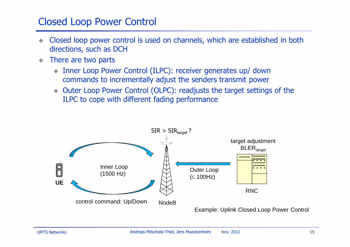
Closed Loop Power Control
Closed loop power control is used on channels, which are established in both directions, such as DCHThere are two parts
Inner Loop Power Control (ILPC): receiver generates up/ down commands to incrementally adjust the senders transmit powerOuter Loop Power Control (OLPC): readjusts the target settings of the ILPC to cope with different fading performance
NodeB
UE
control command: Up/DownExample: Uplink Closed Loop Power Control
Inner Loop(1500 Hz)
SIR > SIRtarget ?
Outer Loop( 100Hz)
target adjustmentBLERtarget
RNC

UMTS Networks 16Andreas Mitschele-Thiel, Jens Mueckenheim Nov. 2011
Impact of Power Control
-8
-6
-4
-2
0
2
4
6
0 0.2 0.4 0.6 0.8 1
pow
er/
fadi
ng [
dB]
time [sec]
2
3
4
5
6
7
8
0 0.2 0.4 0.6 0.8 1
E b/N
0[d
B]
speed = 3 km/h
Example: UMTS Closed Loop Power Control in the slow fading channel

UMTS Networks 17Andreas Mitschele-Thiel, Jens Mueckenheim Nov. 2011
Power Control Performance
5
5.5
6
6.5
7
7.5
0 20 40 60 80 100 120Velocity [km/h]
Requ
ired
UL
SIR
[dB]
PedAVehA
SIR requirement strongly depends on the environment (due to different fast fading conditions – Jakes models)
outer loop power control needed to adapt SIR

UMTS Networks 18Andreas Mitschele-Thiel, Jens Mueckenheim Nov. 2011
Open Loop Power Control
Open loop power control is used on channels that cannot apply closed loop power control, e.g. RACH, FACHThe transmitter power is determined on the basis of a path loss estimate from the received power measure of the opposite directionTo avoid excessive interference, probes with incremental power steps until a response is obtained: “power ramping”
NodeB
UE
Open Loop Power Control on RACH

UMTS Networks 19Andreas Mitschele-Thiel, Jens Mueckenheim Nov. 2011
CDMA Overload
• CDMA systems tend to become unstable– More traffic increases the
interference– More interference requires
higher power– More power increases the
interference …
• Methods are required to limit the system load– Restrict the access to the
system– Overcome overload
situations
UMTS Networks 20Andreas Mitschele-Thiel, Jens Mueckenheim Nov. 2011
Interference in CDMA Networks
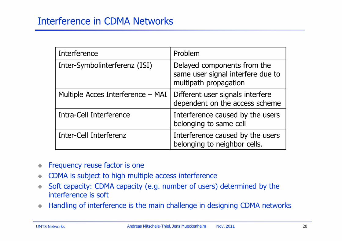
Frequency reuse factor is oneCDMA is subject to high multiple access interferenceSoft capacity: CDMA capacity (e.g. number of users) determined by the interference is softHandling of interference is the main challenge in designing CDMA networks
Interference Problem
Inter-Symbolinterferenz (ISI) Delayed components from the same user signal interfere due to multipath propagation
Multiple Acces Interference – MAI Different user signals interfere dependent on the access scheme
Intra-Cell Interference Interference caused by the users belonging to same cell
Inter-Cell Interferenz Interference caused by the users belonging to neighbor cells.

UMTS Networks 21Andreas Mitschele-Thiel, Jens Mueckenheim Nov. 2011
Cell Breathing
CDMA systems: cell size depends on the actual loadingAdditional traffic will cause more interferenceIf the interference becomes too strong, users at the cell edge can no more communicate with the basestation
CDMA interference managementRestriction of the users access necessaryCell breathing makes network planning difficult
Example: cell brething with increasing traffic
UMTS Networks 22Andreas Mitschele-Thiel, Jens Mueckenheim Nov. 2011
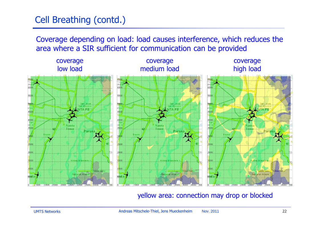
Cell Breathing (contd.)
coverage low load
coverage medium load
coverage high load
Coverage depending on load: load causes interference, which reduces the area where a SIR sufficient for communication can be provided
yellow area: connection may drop or blocked

UMTS Networks 23Andreas Mitschele-Thiel, Jens Mueckenheim Nov. 2011
Coverage vs. Capacity
Capacity depends on:QoS of the users (data rate, error performance (bit-error-rate))User behaviour (activity)Interference (out of cell)Number of carriers/ sectors
Coverage (service area) depends on:Interference (intra- & inter-cell) + noisePathloss (propagation conditions)QoS of the users (data rate, error performance (bit-error-rate))
Thus, trade-off between capacity and coverage

UMTS Networks 24Andreas Mitschele-Thiel, Jens Mueckenheim Nov. 2011
Coverage vs. Capacity
Downlink limits capacity while uplink limits coverageDownlink depends more on the load (users share total transmit BS power)
0 20 40 60 80 100 120 140 160 180 2000
0.5
1
1.5
2
2.5
3
3.5
Downlink
Uplink
Erlangs (2% GOS)
Max
imum
cel
l rad
ius
(km
)
13kbps circuit switched service capacity versus maximum cell radius
UMTS Networks 25Andreas Mitschele-Thiel, Jens Mueckenheim Nov. 2011
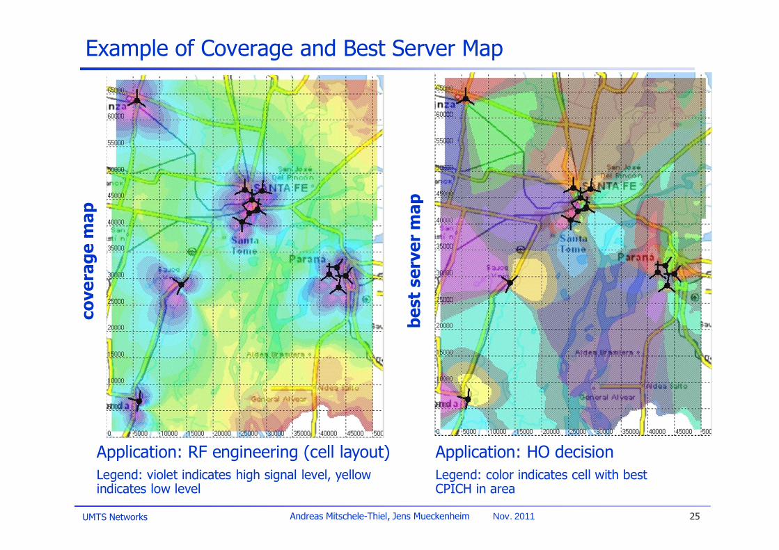
Example of Coverage and Best Server Map
Application: RF engineering (cell layout)Legend: violet indicates high signal level, yellow indicates low level
cove
rage
map
Application: HO decisionLegend: color indicates cell with best CPICH in area
best
ser
ver
map

UMTS Networks 26Andreas Mitschele-Thiel, Jens Mueckenheim Nov. 2011
Load Control: Basics
Main objective:Avoid overload situations by controlling system loadMonitor and controls radio resources of users
Call Admission Control (CAC)Admit or deny new users, new radio access bearers or new radio linksAvoid overload situations, e.g. by means of blocking the requestDecisions are based on interference and resource measurements
Congestion Control (ConC)Monitor, detect and handle overload situations with the already connected usersBring the system back to a stable state, e.g. by means of dropping an existing call

UMTS Networks 27Andreas Mitschele-Thiel, Jens Mueckenheim Nov. 2011
Resource Consumption
• Service/BLER-dependent resource consumption
• Uplink example:– Service I: Voice
Rb = 12.2kbps, Eb/Nt = 5dBI = 0.99%
– Service II: DataRb = 144kbps, Eb/Nt = 3.1dB
II = 7.11%
• In downlink there is additional dependency on the location of the user– Cell center low
consumption– Cell edge high
consumption

UMTS Networks 28Andreas Mitschele-Thiel, Jens Mueckenheim Nov. 2011
Admission/ Congestion Control
Basic algorithm• Admission control is triggered
when load thr_CAC– New users are blocked– Existing users are not
affected as long as load < thr_ConC
• Congestion Control is triggered when load thr_ConC– Reduce consumption of one
or several users– Simple action: drop the user– Repeat until load <
thr_ConC

UMTS Networks 29Andreas Mitschele-Thiel, Jens Mueckenheim Nov. 2011
0%
5%
10%
15%
20%
25%
30%
35%
40%
45%
50%
5 15 25 35 45 55
Offered Traffic [Erlang per s ite ]
Blo
ckin
g Pr
obab
ility
thr_CAC = 50%thr_CAC = 75%thr_CAC = 90%
0%
2%
4%
6%
8%
10%
12%
14%
16%
18%
20%
5 15 25 35 45 55
Offered Traffic [Erlang per s ite]
Dro
ppin
g Pr
obab
ility
thr_CAC = 50%thr_CAC = 75%thr_CAC = 90%
Tradeoff between blocking and droppingExample: 64k per user, urban
Call Admission Control: Simulation Results I

UMTS Networks 30Andreas Mitschele-Thiel, Jens Mueckenheim Nov. 2011
0%
10%
20%
30%
40%
50%
60%
70%
80%
90%
5 15 25 35 45 55
Offered Traffic [Erlang per site]
Cell
Load
ing
thr_CAC = 50%thr_CAC = 75%thr_CAC = 90%
Cell load depending on CAC thresholdExample: 64k per user, urban
Call Admission Control: Simulation Results II

UMTS Networks 31Andreas Mitschele-Thiel, Jens Mueckenheim Nov. 2011
Packet Data Control: Channel Switching
Flexibility of packet servicesAsymmetrical data ratesVery low to very high data ratesControl information/user information
Efficient transmission making good use of CDMA characteristicsDedicated channel (DCH)
Minimise transmission power by closed-loop power controlIndependence between uplink and downlink capacity
Common channelRandom access in the uplink (RACH)Dynamic scheduling in the downlink (FACH)
Adaptive channel usage depending on traffic characteristicsInfrequent or short packets Common channel (Cell_FACH)Frequent or large packets Dedicated channel (Cell_DCH)No packet transmission UE “stand by” modus (URA_PCH)

UMTS Networks 32Andreas Mitschele-Thiel, Jens Mueckenheim Nov. 2011
CELL_DCH CELL_FACH CELL_DCH
Page Download Time Reading Time
DCH Active Time“Chatty Applications”
Channel Switching – Example
Example: Web serviceChatty apps.: keep alive message, stock tickers, etc.(e.g. 100 bytes every 15 sec)Second stage: when no activity in CELL_FACH then switch to URA_PCH

UMTS Networks 33Andreas Mitschele-Thiel, Jens Mueckenheim Nov. 2011
Power Control:– Balances user received quality (BLER, SIR)– Users at cell center get less share of BTS
transmit power assigned than at cell edge– Occurrence of power overload
Rate Adaptation:– Transmit power ~ data rate– Users at cell edge get lower data rate assigned
than at cell center– Reduces also power overload
On DCH combination of power control and rate adaptation
– Rate assignment at begin of a transmission based on load and user location
– Rate adaptation when ongoing transmission according to power consumption and overload
– Based on RRC-signaling (time horizon: 100msec … 10sec)
NodeB
UE 1
UE 2low data rate
area
high data ratearea
Power Control vs. Rate Adaptation

UMTS Networks 34Andreas Mitschele-Thiel, Jens Mueckenheim Nov. 2011
Rate Adaptation Performance
Rate adaptation significantly improves the RRM performance on DCH.
UMTS_urban, 50 kByte
0%
5%
10%
15%
20%
25%
30%
35%
40%
200 300 400 500 600
Cell Throughput [kBit/sec]
Out
age
Prob
abili
ty
384k64kadaptive
UMTS_urban, 50 kByte
0
1
2
3
4
5
6
7
8
200 300 400 500 600
Cell Throughput [kBit/sec]M
ean
Del
ay [s
ec]
384k64kadaptive
UMTS Networks 35Andreas Mitschele-Thiel, Jens Mueckenheim Nov. 2011
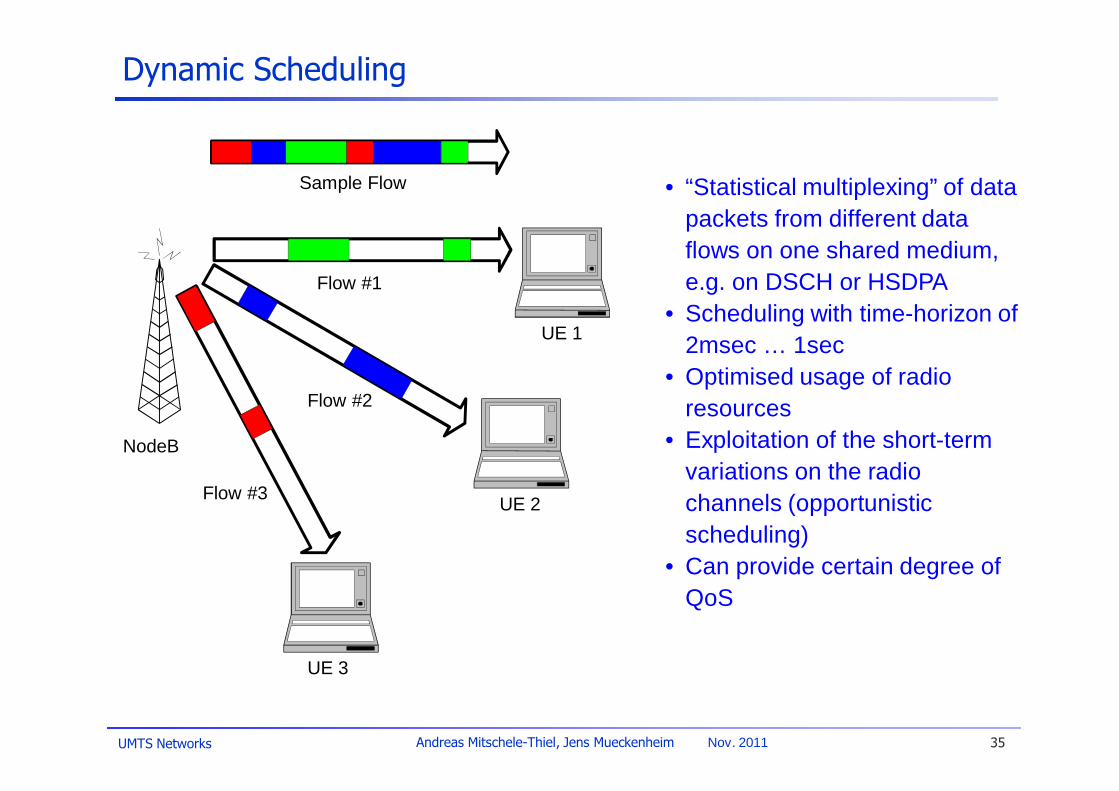
Dynamic Scheduling
• “Statistical multiplexing” of data packets from different data flows on one shared medium, e.g. on DSCH or HSDPA
• Scheduling with time-horizon of 2msec … 1sec
• Optimised usage of radio resources
• Exploitation of the short-term variations on the radio channels (opportunistic scheduling)
• Can provide certain degree of QoS
NodeB
Sample Flow
Flow #1
Flow #3
UE 3
UE 2
UE 1
Flow #2

UMTS Networks 36Andreas Mitschele-Thiel, Jens Mueckenheim Nov. 2011
Summary/ Outlook
Basic RRM algorithms presented here:Handover ControlPower ControlLoad ControlPacket Data Control
RRM procedures not discussed here:Spreading code managementRRM for TDD mode: time-slot management
Related issue: RF engineering
With HSPA scope of resource allocation has been changed esp. for packet dataDynamic scheduling in NodeB to quickly (re)allocate radio resourcesDistribution of RRM between NodeB and RNC