Embed Size (px)
Citation preview
UV-LIGA Microfabrication of a Power Relay Based on Electrostatic Actuation
Louisiana State University
Ren Yang, Seok Jae Jeong, and Wanjun Wang
Department of Mechanical EngineeringLouisiana State University
Baton Rouge, LA 70810USA

1. Introduction.2. Design3. Fabrication 4. Summary & Future work
1. Introduction
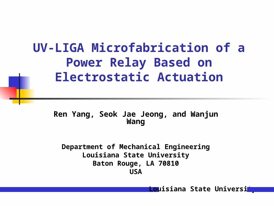
Different Types of Power RelaysDifferent Types of Power Relays
1. Traditional Relay- Advantage: low on resistance, off-leakage, and big
output capacitance- Disadvantage: large, noisy, slow, and difficult to
integrate2. Solid-state Relay
- Advantage: much longer life time, fast response, low noisy, smaller size
- Disadvantage: high on-resistance, low off-resistance, high power consumption, and poor electrical isolation
3. MEMS (Micro Electro Mechanical System) Relay- Takes advantages from traditional and solid-state relay
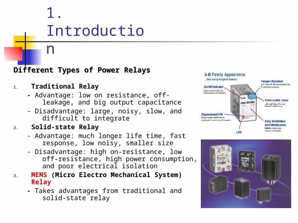
General Principle Commonly Used MEMS Design
Electrostatic force
Magnetomotive force
Piezoelectrical force

Schematic diagram of the micro power relay
2. Design

Differences Compared to Other MEMS Relays
Not silicon based
Metal/Alloy as basic materials such as Ni or Cu for conductivity
Thick metal/Alloy pads can be used instead of thin metal films as silicon based relay
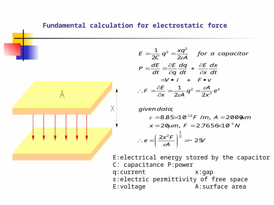
Fundamental calculation for electrostatic force
VA
Fxe
NFmx
mAmF
datagiven
ex
Aq
Ax
EF
vFiV
dt
dx
x
E
dt
dq
q
E
dt
dEP
capacitoraforA
xqq
CE
25~2
107656.2,20
2000,/1085.8
;
22
1
22
1
2
12
7
12
22
2
22
Ax
E:electrical energy stored by the capacitorC: capacitance P:powerq:current x:gapε:electric permittivity of free spaceE:voltage A:surface area
3. Fabrication of micro-relay by UV-LIGA
What is UV-LIGA?
; Approach where a UV aligner is used with a thick resist in place of the synchrotron x-ray exposure step. After the lithography, electrodeposition and planarization are used to produce metal micropart.
Advantages
- High aspect-ratio microfabrication
- Broad selection of materials
- Slightly lower quality and much lower fabrication cost compared to X-ray LIGA

Fabrication Method
Polymer connectorsInsulator to protect
short- circuit
Substrate (Si)
1st layer
Poles to support top part15 m
Substrate (Si)
1st layer
3rd layer2nd layer
Top partBottom part
Assemble
Poles to support top part15 m
Substrate (Si)
1st layer
3rd layer2nd layer
Substrate (Si)
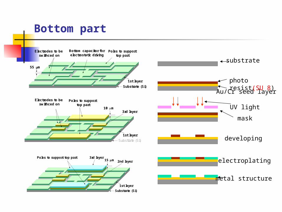
Electrodes to be swithced on
Poles to support top part
10 m
1st layer
3rd layer
Bottom capacitor for electrostatic driving
Electrodes to be swithced on
Poles to support top part
55 m
Substrate (Si)
1st layer
Bottom part
substrate
Au/Cr seed layer
photo resist(SU 8)
UV light
mask
developing
electroplating
metal structure
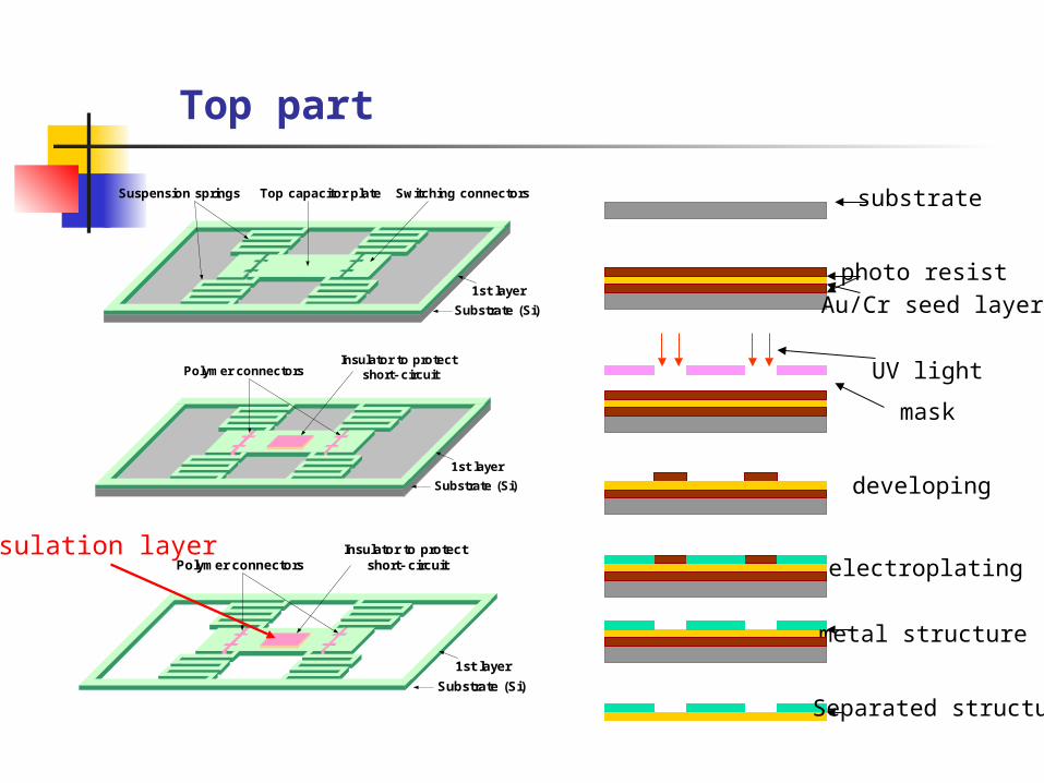
Top part
Insulation layerPolymer connectors
Insulator to protect short- circuit
Substrate (Si)
1st layer
Polymer connectorsInsulator to protect
short- circuit
Substrate (Si)
1st layer
Suspension springs Switching connectorsTop capacitor plate
Substrate (Si)
1st layer
substrate
Au/Cr seed layer
photo resist
UV light
mask
developing
electroplating
metal structure
Separated structure
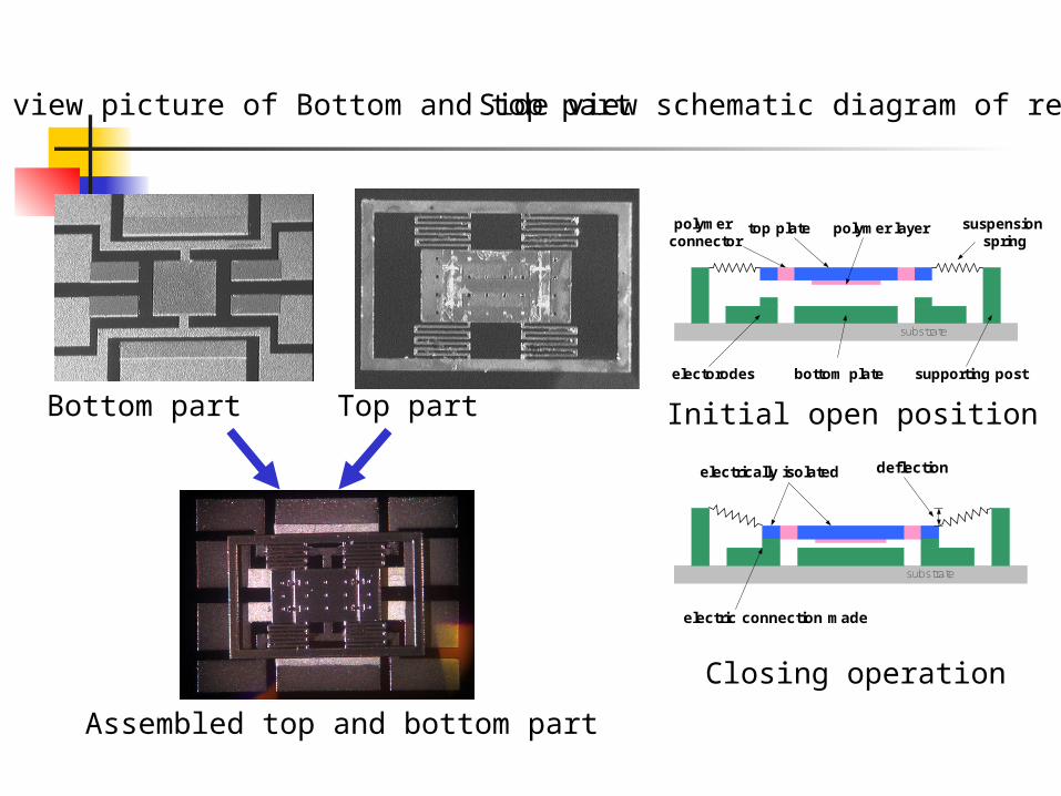
Top view picture of Bottom and top part Side view schematic diagram of relay
Initial open position
Closing operation
Bottom part Top part
Assembled top and bottom part
top plate
bottom plate supporting postelectorodes
suspension spring
polymer layerpolymer connector
substrate
electric connection made
deflectionelectrically isolated
substrate
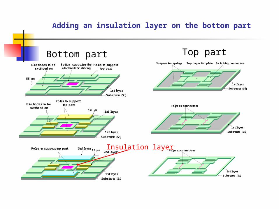
Adding an insulation layer on the bottom part
Bottom part Top part
Insulation layerPoles to support top part15 m
Substrate (Si)
1st layer
3rd layer2nd layer
Substrate (Si)
Electrodes to be swithced on
Poles to support top part
10 m
1st layer
3rd layer
Bottom capacitor for electrostatic driving
Electrodes to be swithced on
Poles to support top part
55 m
Substrate (Si)
1st layer
Suspension springs Switching connectorsTop capacitor plate
Substrate (Si)
1st layer
Polymer connectors
Substrate (Si)
1st layer
Polymer connectors
Substrate (Si)
1st layer
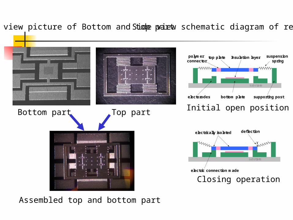
top plate
bottom plate supporting postelectorodes
suspension spring
Insulation layerpolymer connector
substrate
Top view picture of Bottom and top part Side view schematic diagram of relay
Initial open position
Closing operation
Bottom part Top part
Assembled top and bottom part
electric connection made
deflectionelectrically isolated
substrate

4. Preliminary test of assembled relay
Mass Deflection
Mechanical properties
Measurement of deflection by applied weight
1.0x10⁻⁴
2.0x10⁻⁴
3.0x10⁻⁴
4.0x10⁻⁴
2.0x10⁻⁷
4.0x10⁻⁷
6.0x10⁻⁷
Slope(K)=1.75*10-3
Slope(K)=2.13*10-3
experiment simulation
For
ce (
N)
Deflection (m)
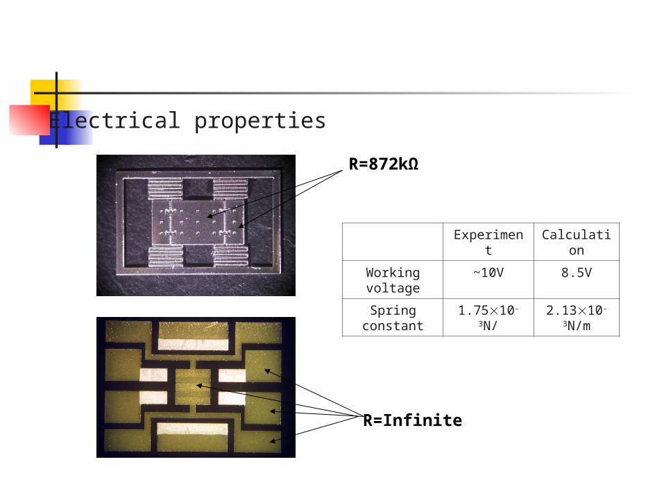
Experiment Calculation
Working voltage
~10V 8.5V
Spring constant 1.7510-3N/ 2.1310-
3N/m
Electrical properties
R=872kΩ
R=Infinite

4. Summary
Design of a novel micro-relay for power applications based on electrostatic actuation
Fabrication by UV-LIGA
Preliminary test Control voltage: 10V Spring constant: 1.7510-3N/m
I
5. Future Work
Improve fabrication process Low stress plating condition Easy way separate top structure from the substrate.
Measure physical properties Spring constant Strength of polymer connector
Test working properties of the assembled power relay
On/off resistance Life time reliability