Embed Size (px)
Citation preview
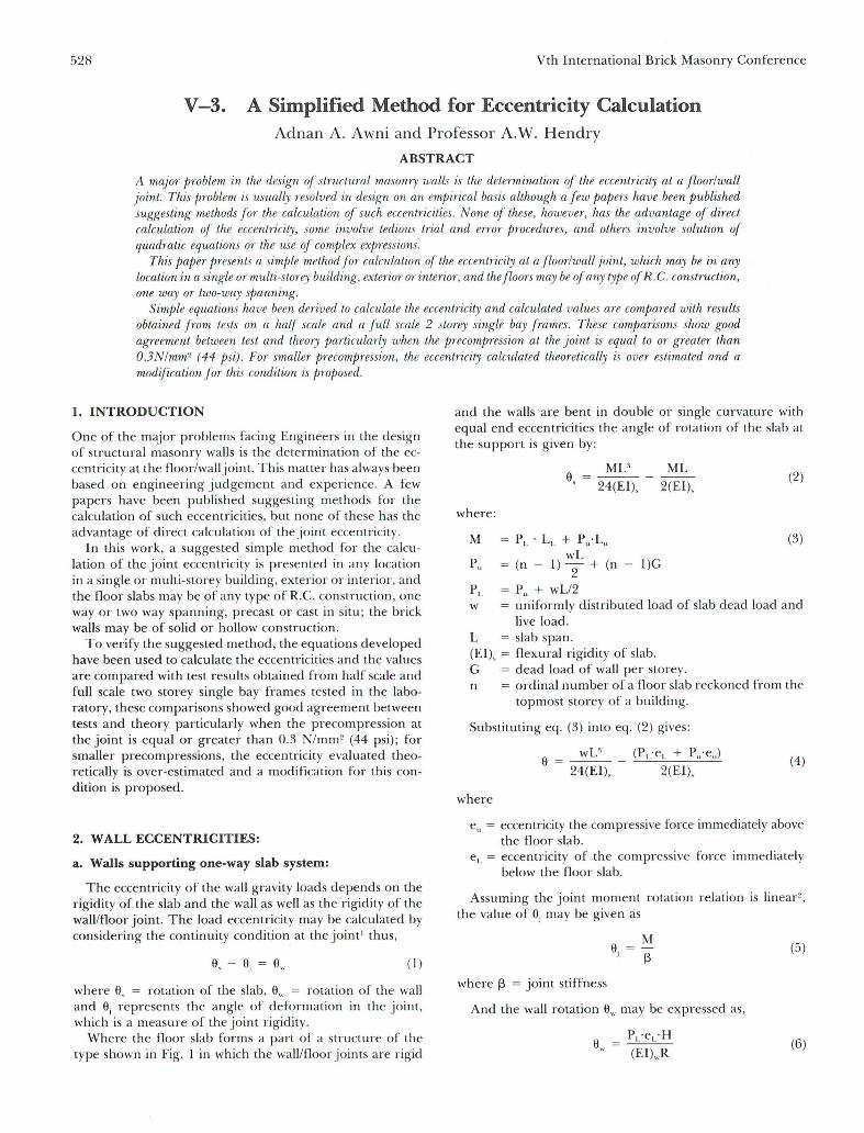
528 Vth International Brick Masonry Conference
V -3. A Simplified Method for Eccentricity Calculation Adnan A. Awni and Professor A.W. Hendry
ABSTRACT
A major !Jroblem in the design of struetural masonry walls is the determination of the eccentricity at a floorlwall joint. This problem is llsually resolved in design on an empirieal basis although a f ew papers have been published suggesting methods for the calculation of sueh eeeentricities. None of t!tese, however, has the advantage of direet ealculation of the eccentricity, some involve tedious tTial and errar proeedures, and others involve solu/ion of qlladratie eqllations ar the use of comPlex expressions.
This papa presents a súnple method for caleulation of the eeeentTicity at a floor/wall joint, whieh may be in any loeation in a single ar multi-storey building, exterior ar interior, and the flOO1"S may be of any type of R. C. construetion, one way ar two-way spanning.
SimPle equations have been derived to calculate the eeeentricity and calculated values are cornpw'ed wilh results obtained from tests on a half scale and a full scale 2 stoTey single bay frames . These comparisons show good agTeement between test and theory particulaTly when the preeompression at the joint is equal to ar greateT than O.3N/mm" (44 psi) . For smalleT pTeeompTession, the eeeentTicity ealculated theoretieally is oveT estimated and a modification for this condition is pTOposed.
1. INTRODUCTION
One of the major problems facing Engineers in the design of structural masonry walls is the determination of the eccentricity at the floor/walljoint. This matter has always been based on engineering judgement and experience. A few papers have been published suggesting methods for the calculation of such eccentricities, but none of these has the advantage of direct calcu lation of the joint eccentricity .
and the walls are bent in double or single curvature with equal end eccentricities the angle of rotation of the slab at the support is given by:
In this work, a suggested sim pie method for the calculation of the joint eccentricity is presented in any location in a single or multi-storey building, exterior or interior, and the floor slabs may be of any type of R.C. conslruction , one way or two way spanning, precast or cast in situ ; the brick walls may be of solid or hollow construction.
To verify the suggested method, the equations developed have been used to calculate the eccentricities and the values are compared with test results obtained from half scale and full scale two storey single bay frames tested in the laboratory, these com pari sons showed good agreement between tests and theory particularly when the precompression at the joint is equal or greater than 0.3 N/mm" (44 psi) ; for smaller precompressions, the eccentricity evaluated theoretically is over-estimated and a modification for this condition is proposed.
2. W ALL ECCENTRICITIES:
a. Walls supporting one-way slab system:
The eccentricity of the wall gravity loads depends on the rigidity of the slab and the wall as well as the rigidity of the walllfloor joint. The load eccentricity may be calculated by considering the continuity condition at the joint' thus,
(1)
where 0, = rotation of the slab, a" rotation of the wall and ai represents the angle of deformation in the joint, which is a measure of the joint rigidity.
Where lhe floor slab forms a part of a structure or lhe type shown in Fig. 1 in which the walllfloor joints are rigid
MU ML a =---, 24(EI), 2(EI),
(2)
where :
M (3)
PL = Pu + wLl2 w = uniformly distributed load of slab dead load and
live load. L = slab span. (EI), = flexural rigidity of slab. G = dead load of wall per storey. n = ordinal number of a floor slab reckoned from the
topmost storey of a building.
Substituting eq. (3) into eq. (2) gives :
wU (PL' eL + Pu'eJ a=---24(EI), 2(EI),
(4)
where
eu = eccentricity the compressive force immediately above the floor slab.
eL = eccentricity of the compressive force immediately below lhe floor slab.
Assuming the joint moment rOlation relation is linear" , the value of ai may be given as
a, (5)
where f3 = joinl stiffness
And the wall rotation a" may be expressed as,
P 'e ·H a = L L
" (EI).,R (6)

Session V, Paper 3, A Simplified M ethod for EccentTicity Calculation
in which H is the distance from walllfloor joint to point of inflection or the wall story height (which ever is smaller), R is a factor depending on the eccentricity, wall slenderness and type of wall curvature and (EI)" is the fle~(Ural rigidity of the wall. Thus substituting eq. (4), (5) and (6) into equation (I) and noting th.at, as previously assumed, e = eu = e L we obtain,
where
M c = --~----------~---=~7
PL ·t[(1 + t\J)(I + r3) + K/R]
c = e/t,
K
M
2(EI),
r3L ' 2(EI),H
(EI)wL
wL' 12 '
t\J = P) PL
(7)
Assuming a rigid joint i.e. r3~oo, it follows that ~~O and eq. (7) redllces to the form:
(8)
where;ji = 1 + t\J
The above eqllation is based on the assumption that the joint is fixed, so that equation (8) is valid in calculating the eccentricities provided that this condition applies and Lhe fixed end moment, M, could be reached if there was no rotation of the joint as a whole. Experiments show that fixity ofthejoint may never be fully achieved in actual SLrllctures (and hence the full fixed end moment, M, may never be fully developed).
Introducing the relation",
Mu = Mt\J (9)
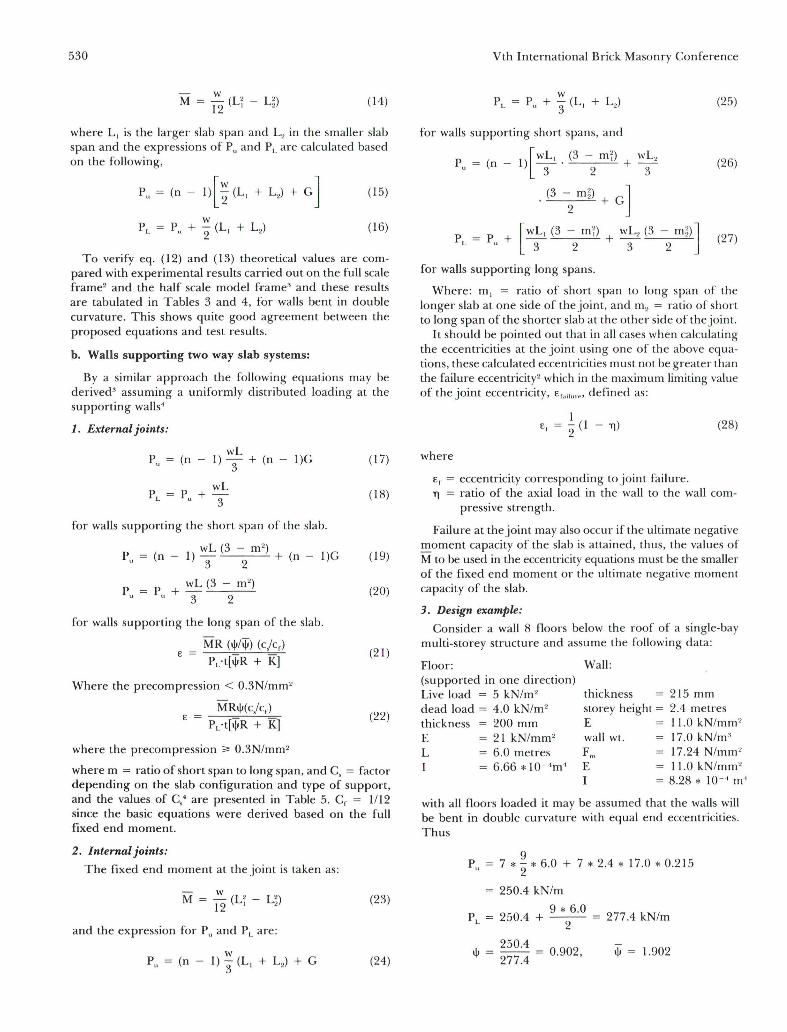
where Mo = actual moment in thejoint (i.e. slab restraining moment) . Equation (9) is presented graphically in Fig. 2, it relates the actual moment at the joint, M", and the slab fixed end moment, M, depending on the degree ofthejoint fixity as a measure of the total precompression at the joint, thllS, when the precompression is equal to zero (i.e. Pu = O) , as the uppermost slab in a multi-storey building, the joint moment M" is equal to zero , simulating a hinged support where the slab is free to rotate. As the precompression increases , the value of P j P L increases, and hence the slab restraining moment increases, thus when the value of t\J approaches unity, the joint becomes fully fixed, and M" is equal to the fixed end moment, M.
To verify equation (9), theoretical values of M" were compared with test results carried out on a full scale two storey frame 2 where the precompression varied from zero to 0.7 N/mm2 (101 psi) and a half scale model ' with precompression up to 1.64 N/mm2 (237 psi) . These comparisons show good agreement between eq. (9) and the test results for precompression greater than 0.3 N/mm2 but gave over estimated values of Mo for smaller precompression, thllS, a
529
modification of eq. (9) is proposed which was compared with test results and gave close agreement. This proposed modification is given as:
M" MWt\J) (10)
Thus, where the precompression on thejoint is less than 0.3 N/mm2 (44 psi), equation (10) shollld be used LO calculate the moment at the joint, and equation (9) is used when the precompression is equal or greater than 0.3 N/mm". The limit of application of eq. (9) and (10) are suggested at 0.3 N/mm 2 precompression, it may be found that using the formulas at values slightly above OI' helow this limit, two values for eccentricity could be found, in such cases, the average of the two eccentricities could be adopted. The theoretical results based on the previous conclusions anel the test results are shown in Tables 1 and 2. Using equations (9) and (10) , eq. (8) is rewritten to account for these conditions and we obtain,
(11)
substituting eq. (9) anel (10) into eq. (11) we finally obtain
(12)
where the precompression < 0.3N/mm'
and, MRt\J
c = ---=--'--==-Rt[t\JR + K]
(13)
where the precompression "" 0.3N/mm 2
Equations (12) anel (13) are valid irrespective of the joint location and will be used to calculate the eccentricities at any externai joint in any system where the slab is supporled in one way direction.
The factor R presented in eq. (12) and (13) was evaluated using a computer program which is programmeel to calculate the equations developed by Colville2 for momentrotation equations relating the eccentricity at the joint; the buckling rotation of the wall and the load carry ing capacity of the wall. From these results it was possible to relate the facto r (R), the eccentricity at the joint and the ultimate capacity of the wall end rotation. The values of R to be used in eq. (12) and (13) are",
1. Walls bent in double curvature, R = 2.345 (uncrackcd walls, i.e . E < 1/6) R = 1.275 (cracked walls , c "" 1/6)
2. Walls bent in single curvature; R = 1.85 for crackeel and uncracked walls.
Finally, the eccentricity at Lhe joint may be calcu lated for externai walls supporting one way slab systems by using the appropriate value ofthe factor R anel Lhe related parameters by direct substitution of the values or these parameters involveel as will be shown in lhe e1esign example . .Jt shoulel be explaineel that, where thejoint is an internai one, equations (12) anel i! 3) can still be used provieleel that the fixeel end moment M is taken as the difference between aeljacent slab fixed enel moments, i.e.
530
M = ~ (L2 - U) 12 ' 2
(14)
where L, is the larger slab span and L2 in the smaller slab span and the expressions of Pu and PL are calculated based on the following,
(15)
(16)
To verify eq. (12) and (13) theoretical values are compared with experimental results carried out on the full scale frame2 and the half scale mode! [,r'ame' and these results are tabulated in Tables 3 and 4, for walls bent in double curvature. This shows quite good agreement between the proposed equations and test results.
b. WaIls supporting two way slab systems:
By a similar approach the following equations may be derived' assuming a uniformly distributed loading at the supporting walls'
1. Externai joints:
(n wL
I) "3 + (n - I)G
for walls supporting the short span of the slab.
wL (3 - m ") (n - I) "3 2 + (n - I)G
Pu = P + wL (3 - m2
)
u 3 2
for walls supporting the long span of the slab.
MR (I\I/iji) (C/ Cf) E =
PL·t[I\IR + KJ
Where the precompression < 0.3N/mm 2
MRI\I(c/ c,) E =
PL·t[I\IR + KJ
where the precompression ;;" 0.3N/mm 2
(17)
(18)
(19)
(20)
(21)
(22)
where m = ratio of short span to long span, and C, = factor depending on the slab configuration and type of support, and the values of C,' are presented in Table 5. Cf = 1/12 since the basic equations were derived based on the full fixed end momento
2. Internai joints:
The fixed end moment at the joint is taken as:
M = ~(U - U) 12 ' 2
(23)
and the expression for Pu and P L are:
Pu = (n - I) ~ (L, + L2 ) + G (24)
Vth International Brick Masonry Conference
(25)
for walls supporting short spans , and
1 [WL, (3 - mD
Pu = (n - ) -. + 3 2
(26)
. (3 -2 mD + G]
P =P + - +--'-------"-[WL, (3 - m;) wL2 (3 - m~)]
L u 3 2 3 2 (27)
for walls supporting long spans.
Where : m, = ratio of short span to long span of the longer slab at one side of the joint, and m" = ratio of short to long span of the shorter slab at the other side of the joint.
It should be pointed out that in ali cases when calculating the eccentricities at the joint using one of the above equations, these calculated eccentricities must not be greater than the failure eccentricity2 which in the maximum limiting value of the joint eccentricity, Efa ;!", " , defined as:
1 E, = '2 (I - TI) (28)
where
E, = eccentricity corresponding to joint failure. TI ratio of the axial load in the wall to the wall com
pressive strength.
Failure at the joint may also occur if the ultimate negative moment capacity of the slab is attained, thus, the values of M to be used in the eccentricity equations must be the smaller of the fixed end moment or the ultimate negative moment capacity of the slab.
3. Design example:
Consider a wall 8 floors below the roof of a single-bay multi-storey structure and assume the following data:
Floor: (supported in one direction) Live load = 5 kN/m2
dead load = 4.0 kN/m" thickness 200 mm E 21 kN/mm2
L I
6.0 metres 6 .66 * 1O - 1 m1
Wall :
thickness 215 mm storey height = 2.4 metres E 11 .0 kN/mm 2
wall wt. 17.0 kN/m" 17.24 N/mm" 11.0 kN/mm 2
= 8.28 * 10-" m 1
with ali floors loaded it may be assumed that the walls will be bent in double curvature with equal end eccentricities. Thus
P = L
9 7 * - * 6.0 + 7 * 2.4 * 17.0 * 0.215
2
250.4 kN/m
250.4 9 * 6.0 277.4 kN/m + ---
2
250.4 1\1 =--= 0.902, 1\1 = 1.902
277.4
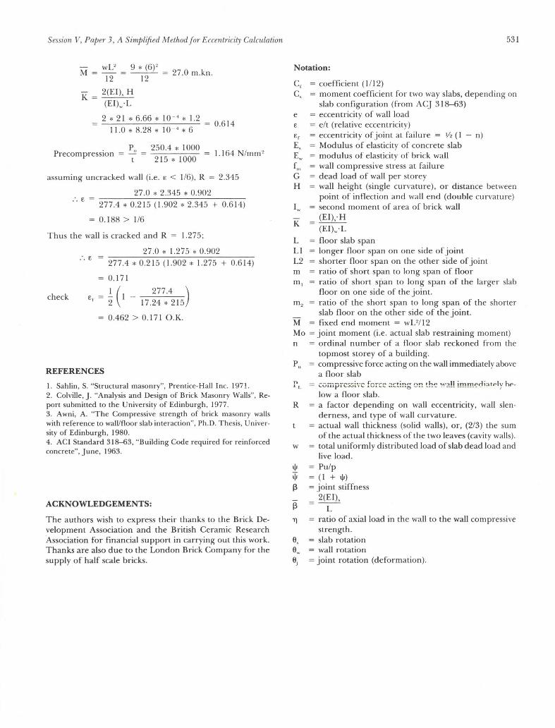
Session V, Papel' 3, A Simplified Method for EccentTicity Calculation
wL2
M=-12
9 * (6)2
12 27.0 m.kn.
K = 2(EI), H (EI).·L
2 * 21 * 6.66 * 10 -" * 1.2 11.0 * 8.28 * 10 - 4 * 6
, Pu PrecompresslOn = -
t
250.4 * 1000 215 * 1000
assuming uncracked wall (i.e. E < 1/6), R
27.0 * 2.345 * 0.902
0.614
1.164 N /mm 2
2.345
:. E 277.4 * 0.215 (1.902 * 2.345 + 0.6 14)
0.188 > 1/6
Thus the wall is cracked and R = 1.275;
27.0 * 1.275 * 0.902 :. E
277.4 * 0.21 5 (1.902 * 1.275 + 0.614)
0.171
check I ( 277.4) Ef 2 I - 17.24 * 215
0.462 > 0.171 O.K.
REFERENCES
I. Sahlin , S, "Structural masonry", Prentice-Hall Inc. 197!. 2. Colville, J. "Analysis and Design of Brick Masonry Walls", Report submitted to the University of Edinburgh , 1977. 3. Awni, A. "The Compressive strength of brick masonry walls with reference to walllfloor slab interaction", Ph.D. Thesis, University of Edinburgh, 1980. 4. ACI Standard 318-63, "Building Code required for reinforced concrete", June, 1963.
ACKNOWLEDGEMENTS:
The authors wish to express their thanks to the Brick Development Association and the British Ceramic Research l\ssociation for financiai support in carrying out this work. Thanks are also due to the London Brick Company for the supply of half scale bricks.
531
Notation:
Cf = coefficient (1/12) C, = moment coefficient for two way slabs, depending on
e E
slab configuration (from AC] 318-63) = eccentricity of wall load = elt (relative eccentricity) = eccentricity of joint at failure = 1/2 (I - n)
E, = Modulus of elasticity of concrete slab E.. = modulus of elasticity of brick wall
K
= wall compressive stress at failure = dead load of wall per storey = wall height (single curvature), OI' distance between
point of inflection and wall end (double curvature) = second moment of area of brick wall
(EI); H (EI).-L
L = floor slab span LI = longer floor span on one side of joint L2 = shorter floor span on the other side of joint m ratio of short span to long span of floor m, ratio of short span to long span of the larger slab
floor on one side of the joint. m, = ratio of the short span to long span of the shorter
slab floor on the other side of the joint. M = fixed end moment = w U I 12 Mo = joint moment (i.e . actual slab restraining moment) n = ordinal number of a floor slab reckoned from the
topmost storey of a building. Pu = compressive force acting on the wall immediately above
a floor slab r L = ~vwpi"'~:;:;i·.'~ fer:::e ::.~t!!"!õ 0!"! the ~~1:!!! i!!!!!!1C"0i ~ tPl y hp
low a floor slab. R = a facto r depending on wall eccentricity, wall slen
derness, and type of wall curvature. = actual wall thickness (solid walls), or, (2/3) the sum
of the actual thickness of the two leaves (cavity walls), w total uniformly distributed load of slab dead load and
live load. 1\1 Pu/p ijJ (I + 1\1) 13 = joint stiffness
2(EI), 13 L
'T]
6,
= ratio ofaxialload in the wall to the wall compressive strength.
= slab rotation S.. = wall rotation
= joint rotation (deformation).
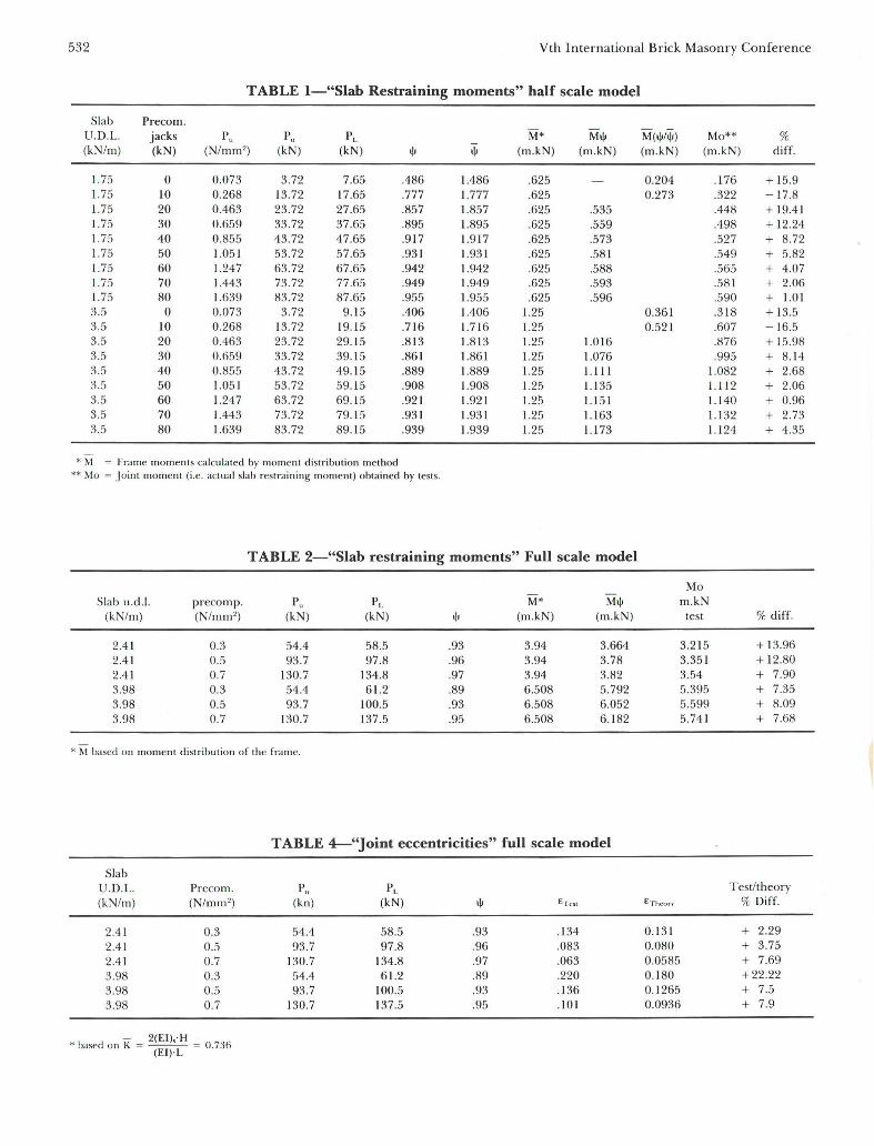
532 Vth International Brick Masonry Conference
TABLE l-"Slab Restraining moments" half scale model
Slab Precom. U.D.L. jacks Pu Pu PL M* Mt\I M(t\I/~) Mo** % (kN/m) (kN) (N/mm' ) (kN) (kN) t\I t\I (m.kN) (m .kN) (m.kN) (m .kN) diff.
1.75 O 0.073 3.72 7.65 .486 1.486 .625 0.204 .176 + 15.9 1.75 10 0.268 13.72 17.65 .777 1.777 .625 0.273 .322 - 17.8 1.75 20 0.463 23.72 27.65 .857 1.857 .625 .535 .448 + 19.4 1 1. 75 30 0.659 33.72 37.65 .895 1.895 .625 .559 .498 + 12.24 1. 75 40 0.855 43.72 47.65 .9 17 1.917 .625 .573 .527 + 8.72 1.75 50 1.051 53.72 57.65 .931 1.931 .625 .581 .549 + 5.82 1.75 60 1.247 63.72 67.65 .942 1.942 .625 .588 .565 + 4.07 1. 75 70 1.443 73.72 77.65 .949 1.949 .625 .593 .581 + 2.06 1.75 80 1.639 83.72 87 .65 .955 1.955 .625 .596 .590 + 1.01 3.5 O 0.073 3.72 9.15 .406 1.406 1.25 0.361 .318 + 13.5 3.5 10 0.268 13.72 19.15 .7 16 1.716 1.25 0.521 .607 - 16.5 3.5 20 0.463 23 .72 29. 15 .813 1.813 1.25 1.01 6 .876 + 15.98 3.5 30 0.659 33.72 39.15 .861 1.861 1.25 1.076 .995 + 8.14 3.5 40 0.855 43.72 49. 15 .889 1.889 1.25 1.111 1.082 + 2.68 3.5 50 1.051 53.72 59. 15 .908 1.908 1.25 1.135 1.112 + 2.06 3.5 60 1.247 63.72 69 .15 .921 1.921 1.25 1.151 1.140 + 0.96 3.5 70 1.443 73.72 79.15 .931 1.931 1.25 1.1 63 1.1 32 + 2.73 3.5 80 1.639 83.72 89. 15 .939 1.939 1.25 1.173 1.124 + 4.35
*M = Frame moments calcu lated by moment distribution method ** Mo = J oint momen t (i.e. aClual slab restraining moment) obtaincd by tests.
T ABLE 2-"Slab restraining moments" FuH scale model
Mo Sla b u.d.J. precomp. Pu PL M* Mt\I m.kN
(kN/m) (N/m m ") (kN) (kN) t\I (m.kN) (m.kN) test % diff.
2.41 0.3 54.4 58.5 .93 3.94 3.664 3.215 + 13.96 2.41 0.5 93.7 97.8 .96 3.94 3.78 3.351 + 12.80 2.41 0.7 130.7 134.8 .97 3.94 3.82 3.54 + 7.90 3.98 0.3 54.4 61.2 .89 6.508 5.792 5.395 + 7.35 3.98 0.5 93.7 100.5 .93 6.508 6.052 5.599 + 8.09 3.98 0.7 130.7 137.5 .95 6.508 6. 182 5.741 + 7.68
• M baseei o n moment distr ibution of the frame.
TABLE 4-"Joint eccentricities" fuH scale model
Slab U.D.L. Precom . Pu PL Testltheory
(kN/m) (N/mm") (kn) (kN) t\I €Tc!'t E "rtll..'o f) % Diff.
2.41 0.3 54.4 58.5 .93 .134 0.131 + 2.29 2.41 0.5 93.7 97.8 .96 .083 0.080 + 3.75 2.41 0.7 130.7 134.8 .97 .063 0.0585 + 7.69 3.98 0.3 54.4 61.2 .89 .220 0. 180 +22.22 3.98 0.5 93.7 100.5 .93 .136 0.1265 + 7.5 3.98 0.7 130.7 137.5 .95 .1 01 0.0936 + 7.9
- 2(EI).-H • baseei on K = --- = 0.736
(EI) ·L
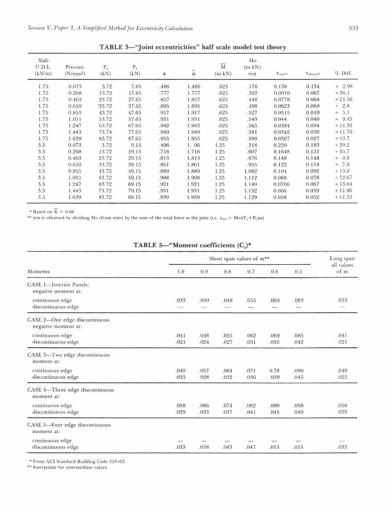
Session V, Papa 3, A SimPlified M ethod for Eccentricity Calculation 533
T ABLE 3-"Joint eccentricities" half scale model test theory
Slab Mo U.D.L. Precom. Pu PL M (m.kN) (kN/m) (N/mm' ) (kN) (kN)
'" '" (m.kN) test E":lol·· EChcory· % Difr.
1.75 0.073 3.72 7.65 .486 1.486 .625 .1 76 0.138 0.134 + 2.98 1.75 0.268 13.72 17.65 .777 1.777 .625 .322 0.0916 0.067 +36. 1 1.75 0.463 23.72 27.65 .857 1.857 .625 .448 0.0778 0.064 + 21.56 1.75 0 .659 -33.72 37.65 .895 1.895 .625 .498 0.0623 0.060 + 2.8 1.75 0.855 43.72 47 .65 .9 17 1.9 17 .625 .527 0.05 15 0.049 + 5.1 1.75 1.05 1 53.72 57.65 .93 1 1.931 .625 .549 0.044 0.040 + 9.45 1.75 1.247 63.72 67.65 .942 1.942 .625 .565 0.0384 0.034 + 11.95 1.75 1.443 73.74 77.65 .949 1.949 .625 .58 1 0.0342 0.030 + 11.76 I. 75 1.639 83.72 87.65 .955 1.955 .625 .590 0.0307 0.027 + 13.7 3.5 0.073 3.72 9. 15 .406 I. 06 1.25 .3 18 0.220 0. 183 +20.2 3.5 0.268 13.72 19. 15 .716 1.7 16 1.25 .607 0.1 648 0. 12 1 +35.7 3.5 0.463 23.72 29. 15 .8 13 1.8 13 1.25 .876 0. 148 0.148 + 0.0 3.5 0.659 33.72 39. 15 .86 1 1.86 1 1.25 .995 0. 122 0. 11 4 + 7.0 3.5 0.855 43.72 49.1 5 .889 1.889 1.25 1.082 0. 104 0.092 + 13.0 3.5 1.05 1 53.72 59. 15 .908 1.908 1.25 1. 11 2 0.088 0.078 + 12.67 3.5 1.247 63 .72 69. 15 .92 1 1.921 1.2!i 1.140 0.0766 0.067 + 13.64 3.5 1.443 73.72 79.15 .93 1 1.93 1 1.25 1.132 0.066 0.059 + 11.86 3.5 1.639 83.72 89. 15 .939 1.939 1.25 1.129 0.058 0.052 + 11.53
* Based on K = 0.66 ** test is obtained by dividing Mo (from tests) by the sum of the total force at the joint (i.e. E"" = Mo/(l'., + Pd*t)
T ABLE 5--"Moment coefficients (Cs)*
Short span values of m** Long span ali values
Moments 1.0 0.9 0.8 0.7 0.6 0.5 ofm
CASE l - Interior Panels: nega tive moment at:
continuous edge .033 .040 .048 .055 .063 .083 .033 discontinuous edge
CASE 2-0ne edge discontinuous negative moment at:
continuous edge .041 .048 .055 .062 .069 .085 .041 discontinuous edge .02 1 .024 .027 .03 1 .035 .042 .02 1
CASE 3-Two edge discontinuous moment at:
continuous edge .049 .057 .064 .07 1 0.78 .090 .049 d iscontinuous edge .025 .028 .032 .036 .039 .045 .025
CASE 4-T hree edge d iscontinuous moment at:
continuous edge .058 .066 .074 .082 .090 .098 .058 discontinuous edge .029 .033 .037 .04 1 .045 .049 .029
CASE 5-Four edge d iscontinuous moment at:
continuous edge discontinuous edge .033 .038 .043 .047 .053 .055 .033
* From ACI Standard Building Codc 318-63. ** I nterpolate for intermediate values.

534
n=l
n=2
n=3 ,~ "
'- .. ' ... -_ Joint
n=4
n=5
-.. -"" Figure 1.
Figure 2.
Vth International Brick Masonry Conference
-n \1 !
Pu
u
H
I Floor Slab
.,) r
e I ~ L P
•
I\~~
1.0 M./M