Embed Size (px)
Citation preview
Keeping the universe connected.
V‐Band Communications Link DesignFor A Hosted Payload
Anthony Zunis, SCaN SIP InternDeboshri Sadhukhan, SCaN SIP Intern
John Alexander, SCaN SIP InternDavid Avanesian, Systems Engineer
Eric Knoblock, Systems EngineerSeptember 9, 2013
Outline1. Introduction
– Task Objectives– Hosted Payload Locations – V‐Band Link Architecture
2. Hosted Payload Study– Hosted Payload Descriptions– Considerations– Satellite Bus Examples– Satellite Specification Summaries
3. V‐Band Communications Link Design & Analysis– Link Budget Description– V‐Band Considerations– MATLab Data and Results– V‐Band Data and Results– Future Work
1. Introduction
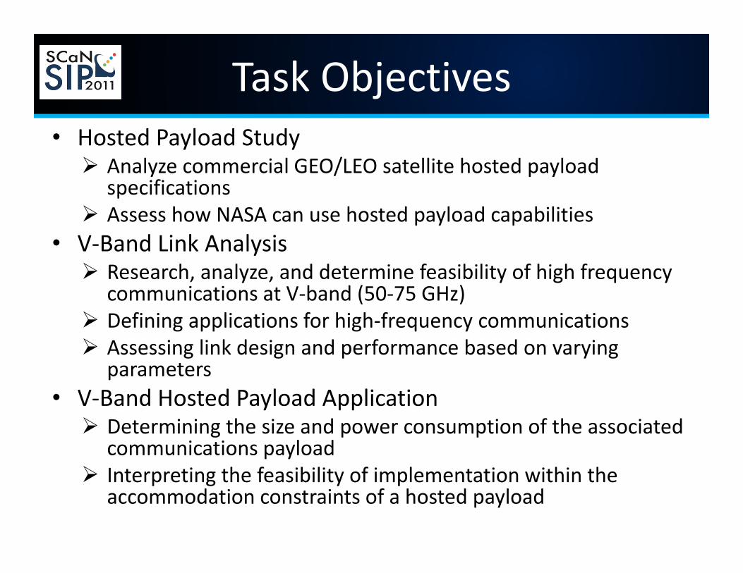
Task Objectives• Hosted Payload Study Analyze commercial GEO/LEO satellite hosted payload
specifications Assess how NASA can use hosted payload capabilities
• V‐Band Link Analysis Research, analyze, and determine feasibility of high frequency
communications at V‐band (50‐75 GHz) Defining applications for high‐frequency communications Assessing link design and performance based on varying
parameters• V‐Band Hosted Payload Application Determining the size and power consumption of the associated
communications payload Interpreting the feasibility of implementation within the
accommodation constraints of a hosted payload

Station
MOC
Geosynchronous Earth Orbit (GEO)
Low Earth Orbit (LEO)
Hosted Payload Locations & Architecture Design for V-Band V-band User Missions
Title: V-Band Architecture High-Level Operational Concept Graphic NISN
Figure/Table/Type: OV-1 Date: 6/21/2011 Version: 1 Figure: 1
Hosted PayloadSatellite GEO (HPSG)
NISN
Hosted PayloadSatellite LEO (HPSL)
2. Hosted Payload Study
What is a Hosted Payload?
• Refers to the utilization of available capacity on commercial satellites to accommodate additional payloads (e.g., transponders, instruments, etc.)
• By offering "piggyback rides“ on commercial communication satellites already scheduled for launch, costumers such as government agencies can send sensors and other equipment into space on a timely and cost‐effective basis.
• Concept is similar to “ridesharing” but instead partners share a satellite bus, rather than a space launch vehicle.
What is a Hosted Payload?
• Some providers offer specific hosted payload accommodations. However, many providers are open to negotiation for space onboard their satellite buses.
• For our study, based on our research, we used 10‐20% of the total satellite capabilities are reserved for payload additions as a rule of thumb.
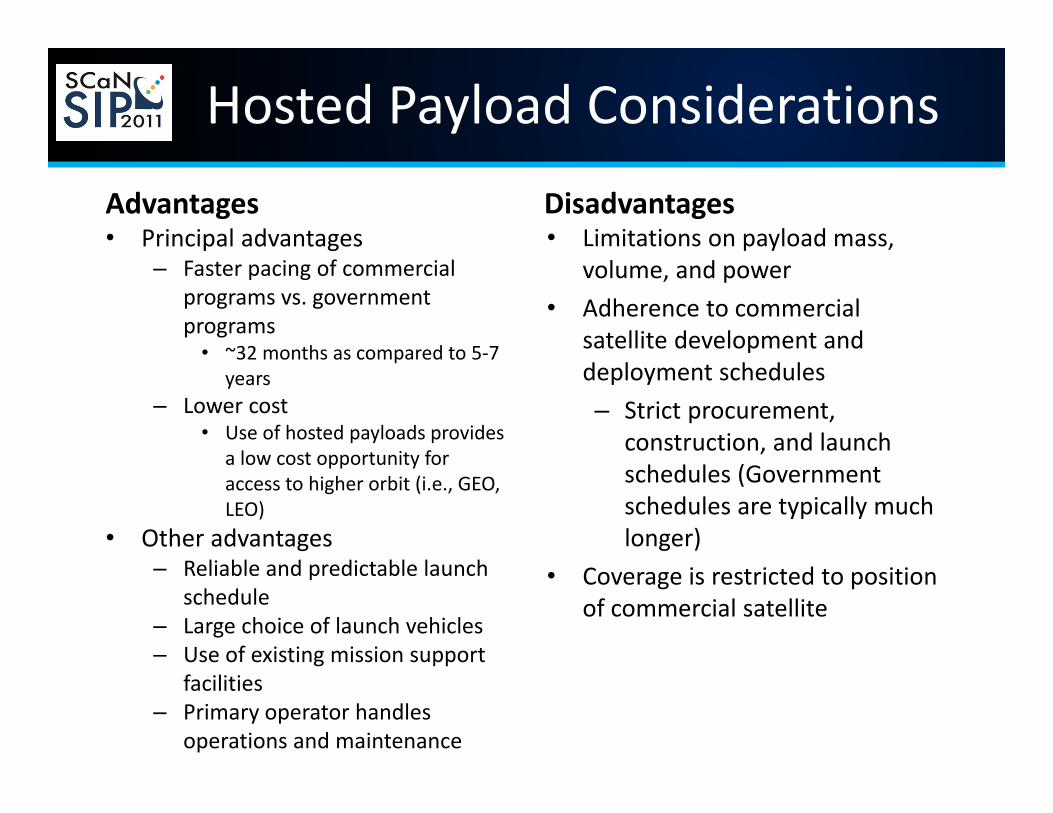
Hosted Payload ConsiderationsAdvantages• Principal advantages
– Faster pacing of commercial programs vs. government programs
• ~32 months as compared to 5‐7 years
– Lower cost• Use of hosted payloads provides
a low cost opportunity for access to higher orbit (i.e., GEO, LEO)
• Other advantages– Reliable and predictable launch
schedule– Large choice of launch vehicles– Use of existing mission support
facilities– Primary operator handles
operations and maintenance
Disadvantages• Limitations on payload mass,
volume, and power• Adherence to commercial
satellite development and deployment schedules– Strict procurement,
construction, and launch schedules (Government schedules are typically much longer)
• Coverage is restricted to position of commercial satellite
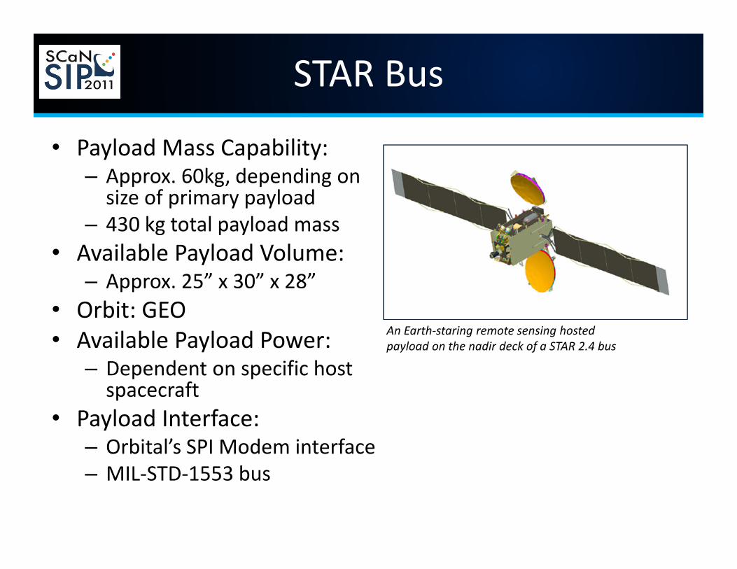
STAR Bus
• Payload Mass Capability:– Approx. 60kg, depending on size of primary payload
– 430 kg total payload mass• Available Payload Volume:
– Approx. 25” x 30” x 28”• Orbit: GEO• Available Payload Power:
– Dependent on specific host spacecraft
• Payload Interface:– Orbital’s SPI Modem interface– MIL‐STD‐1553 bus
An Earth‐staring remote sensing hostedpayload on the nadir deck of a STAR 2.4 bus
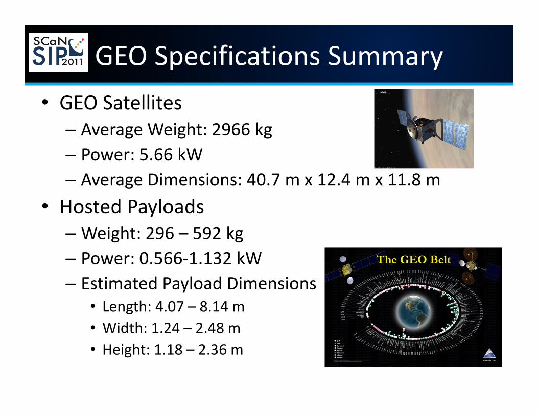
GEO Specifications Summary• GEO Satellites
– Average Weight: 2966 kg– Power: 5.66 kW– Average Dimensions: 40.7 m x 12.4 m x 11.8 m
• Hosted Payloads– Weight: 296 – 592 kg– Power: 0.566‐1.132 kW– Estimated Payload Dimensions
• Length: 4.07 – 8.14 m• Width: 1.24 – 2.48 m• Height: 1.18 – 2.36 m
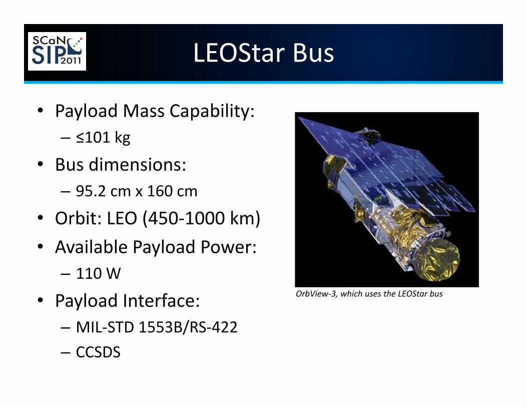
LEOStar Bus
• Payload Mass Capability:– ≤101 kg
• Bus dimensions: – 95.2 cm x 160 cm
• Orbit: LEO (450‐1000 km)• Available Payload Power:
– 110 W
• Payload Interface:– MIL‐STD 1553B/RS‐422– CCSDS
OrbView‐3, which uses the LEOStar bus
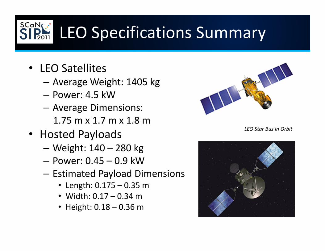
LEO Specifications Summary
• LEO Satellites– Average Weight: 1405 kg– Power: 4.5 kW– Average Dimensions: 1.75 m x 1.7 m x 1.8 m
• Hosted Payloads– Weight: 140 – 280 kg– Power: 0.45 – 0.9 kW– Estimated Payload Dimensions
• Length: 0.175 – 0.35 m• Width: 0.17 – 0.34 m• Height: 0.18 – 0.36 m
LEO Star Bus in Orbit
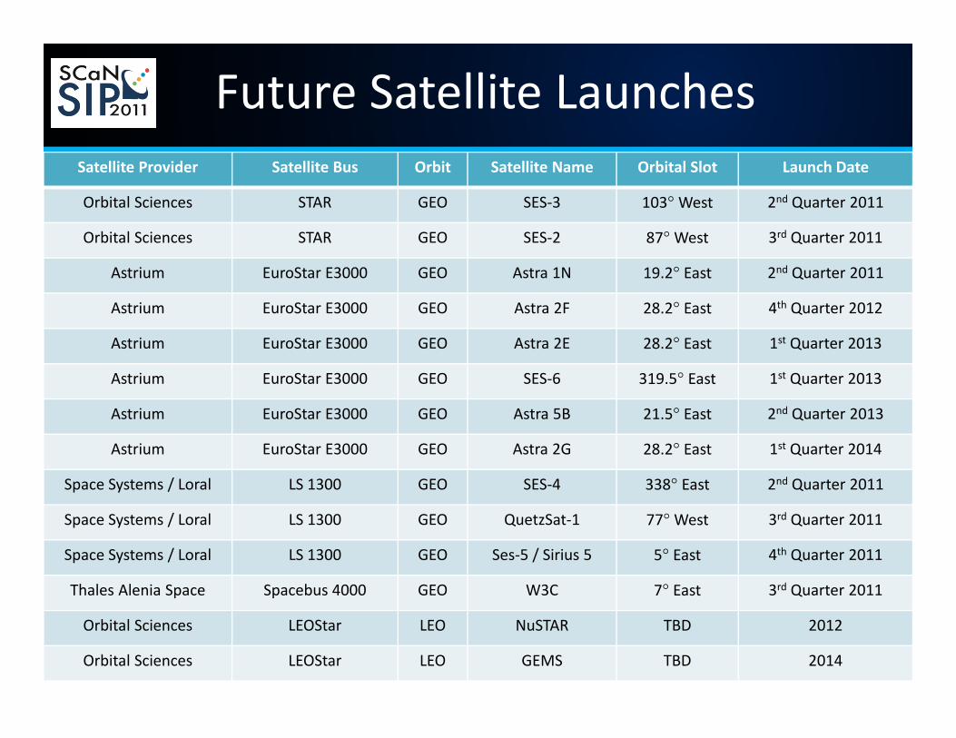
Future Satellite LaunchesSatellite Provider Satellite Bus Orbit Satellite Name Orbital Slot Launch Date
Orbital Sciences STAR GEO SES‐3 103°West 2nd Quarter 2011
Orbital Sciences STAR GEO SES‐2 87°West 3rd Quarter 2011
Astrium EuroStar E3000 GEO Astra 1N 19.2° East 2nd Quarter 2011
Astrium EuroStar E3000 GEO Astra 2F 28.2° East 4th Quarter 2012
Astrium EuroStar E3000 GEO Astra 2E 28.2° East 1st Quarter 2013
Astrium EuroStar E3000 GEO SES‐6 319.5° East 1st Quarter 2013
Astrium EuroStar E3000 GEO Astra 5B 21.5° East 2nd Quarter 2013
Astrium EuroStar E3000 GEO Astra 2G 28.2° East 1st Quarter 2014
Space Systems / Loral LS 1300 GEO SES‐4 338° East 2nd Quarter 2011
Space Systems / Loral LS 1300 GEO QuetzSat‐1 77°West 3rd Quarter 2011
Space Systems / Loral LS 1300 GEO Ses‐5 / Sirius 5 5° East 4th Quarter 2011
Thales Alenia Space Spacebus 4000 GEO W3C 7° East 3rd Quarter 2011
Orbital Sciences LEOStar LEO NuSTAR TBD 2012
Orbital Sciences LEOStar LEO GEMS TBD 2014

Potential Applications of Hosted Payloads
• Propagation Analysis• Technology Demonstration
– i.e., Internet Routing in Space
• Added Capacity in Space• Space Situational Awareness
– i.e., Collision Avoidance, Debris Monitoring, Nuclear Detection, Radiation Assessment, Streaming and still imagery
• Sensor Package and Instrumentation– i.e., Hyper‐Spectral Sounding, Ocean Color Analysis, Ozone
Mapping, Earth Staring, and Weather Tracking
• Others…
3. V‐Band Communications Link Design & Analysis
What is V‐Band?
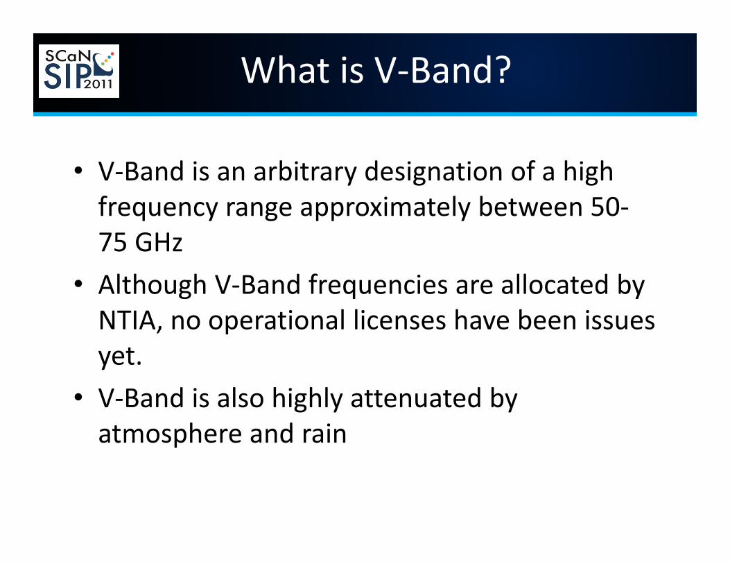
• V‐Band is an arbitrary designation of a high frequency range approximately between 50‐75 GHz
• Although V‐Band frequencies are allocated by NTIA, no operational licenses have been issues yet.
• V‐Band is also highly attenuated by atmosphere and rain

V‐Band ConsiderationsAdvantages• Increased data rate capabilities
for satellite‐to‐ground communications for shorter download time
• Smaller antennas for higher frequency bands reduce the mass on payload
• High frequency transmissions are less likely to be distorted due to interference and low population of users in higher frequency bands
• The higher the data rate, the higher the level of public interest and engagement. Higher rates allow for high‐res images, high‐def video, etc…
Disadvantages
• Space‐Ground Communications– Atmospheric Absorption
• Increased rain attenuation• Resonance of oxygen molecules
• Increased humidity attenuation
– Requires more transmission power
• Not suitable for emergency communications due to atmospheric variability
• Need a more precise attitude control system on the flight platform due to the pointing requirements of the narrow beamwidth
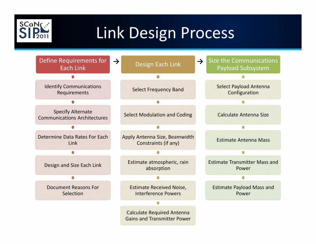
Link Design ProcessDefine Requirements for
Each Link
Identify Communications Requirements
Specify Alternate Communications Architectures
Determine Data Rates For Each Link
Design and Size Each Link
Document Reasons For Selection
Design Each Link
Select Frequency Band
Select Modulation and Coding
Apply Antenna Size, BeamwidthConstraints (if any)
Estimate atmospheric, rain absorption
Estimate Received Noise, Interference Powers
Calculate Required Antenna Gains and Transmitter Power
Size the Communications Payload Subsystem
Select Payload Antenna Configuration
Calculate Antenna Size
Estimate Antenna Mass
Estimate Transmitter Mass and Power
Estimate Payload Mass and Power
→ →
What is a Link Budget?
• A link budget analysis is an analysis of gains and losses within an RF link.
• Gains and losses of the components/factors in the RF path are computed and summed – Result is an estimate of the end‐to‐end system performance in the real world
– This must be done to determine if a sufficient signal strength will be received to meet data rate requirements
Link Budget
• Link Budget Analysis can be performed for both the downlink and uplink, but the parameters used in the calculation varies including:– Uplink power amplifier gain and noise factors– Transmit Antenna Gain– Receiver Antenna and Amplifier Gains and Noise Factors– Atmospheric Attenuation Factors – Slant range and corresponding space loss over a distance
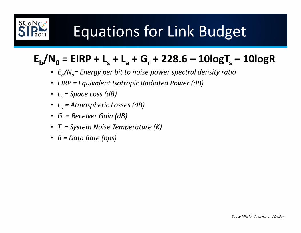
Equations for Link BudgetEb/N0 = EIRP + Ls + La + Gr + 228.6 – 10logTs – 10logR
• Eb/No= Energy per bit to noise power spectral density ratio• EIRP = Equivalent Isotropic Radiated Power (dB)• Ls = Space Loss (dB)• La = Atmospheric Losses (dB)• Gr = Receiver Gain (dB)• Ts = System Noise Temperature (K)• R = Data Rate (bps)
Space Mission Analysis and Design
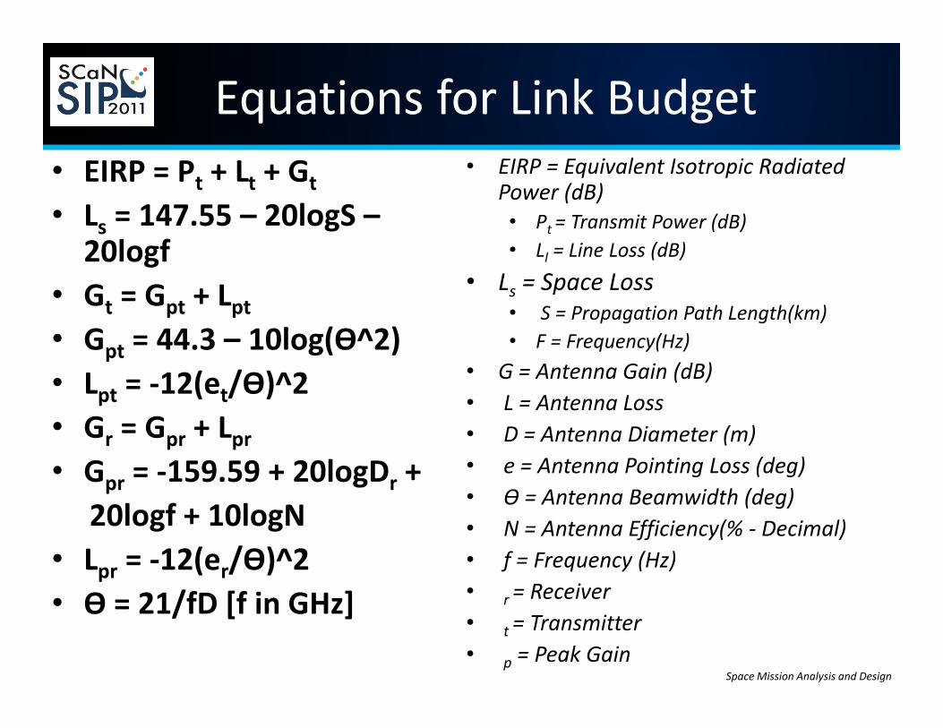
Equations for Link Budget• EIRP = Pt + Lt + Gt
• Ls = 147.55 – 20logS –20logf
• Gt = Gpt + Lpt• Gpt = 44.3 – 10log(Ѳ^2)• Lpt = ‐12(et/Ѳ)^2• Gr = Gpr + Lpr• Gpr = ‐159.59 + 20logDr +
20logf + 10logN• Lpr = ‐12(er/Ѳ)^2• Ѳ = 21/fD [f in GHz]
• EIRP = Equivalent Isotropic Radiated Power (dB)• Pt = Transmit Power (dB)• Ll = Line Loss (dB)
• Ls = Space Loss• S = Propagation Path Length(km)• F = Frequency(Hz)
• G = Antenna Gain (dB)• L = Antenna Loss• D = Antenna Diameter (m)• e = Antenna Pointing Loss (deg)• Ѳ = Antenna Beamwidth (deg)• N = Antenna Efficiency(% ‐ Decimal)• f = Frequency (Hz)• r = Receiver• t = Transmitter• p = Peak Gain
Space Mission Analysis and Design
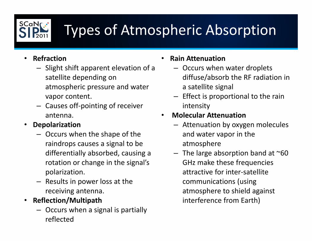
Types of Atmospheric Absorption
• Refraction– Slight shift apparent elevation of a
satellite depending on atmospheric pressure and water vapor content.
– Causes off‐pointing of receiver antenna.
• Depolarization– Occurs when the shape of the
raindrops causes a signal to be differentially absorbed, causing a rotation or change in the signal’s polarization.
– Results in power loss at the receiving antenna.
• Reflection/Multipath– Occurs when a signal is partially
reflected
• Rain Attenuation– Occurs when water droplets
diffuse/absorb the RF radiation in a satellite signal
– Effect is proportional to the rain intensity
• Molecular Attenuation– Attenuation by oxygen molecules
and water vapor in the atmosphere
– The large absorption band at ~60 GHz make these frequencies attractive for inter‐satellite communications (using atmosphere to shield against interference from Earth)
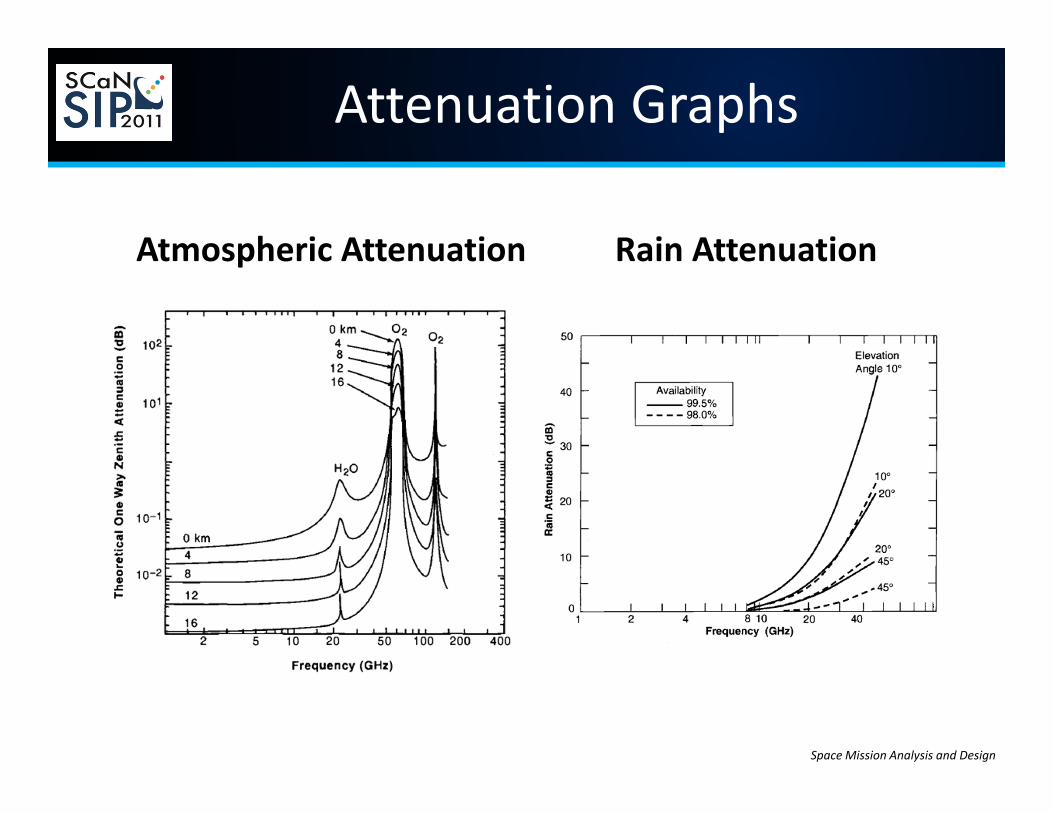
Atmospheric Attenuation Rain Attenuation
Space Mission Analysis and Design
Attenuation Graphs
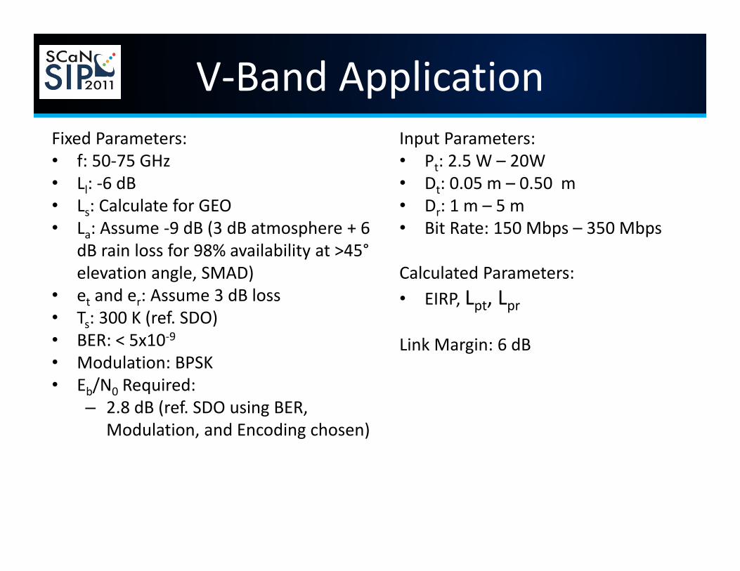
V‐Band ApplicationFixed Parameters:• f: 50‐75 GHz• Ll: ‐6 dB• Ls: Calculate for GEO• La: Assume ‐9 dB (3 dB atmosphere + 6
dB rain loss for 98% availability at >45°elevation angle, SMAD)
• et and er: Assume 3 dB loss• Ts: 300 K (ref. SDO)• BER: < 5x10‐9• Modulation: BPSK• Eb/N0 Required:
– 2.8 dB (ref. SDO using BER, Modulation, and Encoding chosen)
Input Parameters:• Pt: 2.5 W – 20W• Dt: 0.05 m – 0.50 m• Dr: 1 m – 5 m• Bit Rate: 150 Mbps – 350 Mbps
Calculated Parameters:• EIRP, Lpt, Lpr
Link Margin: 6 dB
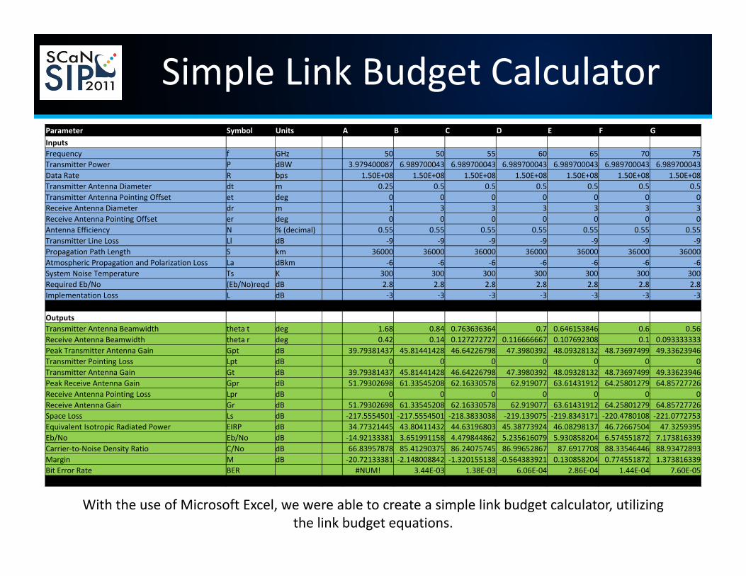
Simple Link Budget Calculator
With the use of Microsoft Excel, we were able to create a simple link budget calculator, utilizing the link budget equations.
Parameter Symbol Units A B C D E F GInputsFrequency f GHz 50 50 55 60 65 70 75Transmitter Power P dBW 3.979400087 6.989700043 6.989700043 6.989700043 6.989700043 6.989700043 6.989700043Data Rate R bps 1.50E+08 1.50E+08 1.50E+08 1.50E+08 1.50E+08 1.50E+08 1.50E+08Transmitter Antenna Diameter dt m 0.25 0.5 0.5 0.5 0.5 0.5 0.5Transmitter Antenna Pointing Offset et deg 0 0 0 0 0 0 0Receive Antenna Diameter dr m 1 3 3 3 3 3 3Receive Antenna Pointing Offset er deg 0 0 0 0 0 0 0Antenna Efficiency N % (decimal) 0.55 0.55 0.55 0.55 0.55 0.55 0.55Transmitter Line Loss Ll dB ‐9 ‐9 ‐9 ‐9 ‐9 ‐9 ‐9Propagation Path Length S km 36000 36000 36000 36000 36000 36000 36000Atmospheric Propagation and Polarization Loss La dBkm ‐6 ‐6 ‐6 ‐6 ‐6 ‐6 ‐6System Noise Temperature Ts K 300 300 300 300 300 300 300Required Eb/No (Eb/No)reqd dB 2.8 2.8 2.8 2.8 2.8 2.8 2.8Implementation Loss L dB ‐3 ‐3 ‐3 ‐3 ‐3 ‐3 ‐3
OutputsTransmitter Antenna Beamwidth theta t deg 1.68 0.84 0.763636364 0.7 0.646153846 0.6 0.56Receive Antenna Beamwidth theta r deg 0.42 0.14 0.127272727 0.116666667 0.107692308 0.1 0.093333333Peak Transmitter Antenna Gain Gpt dB 39.79381437 45.81441428 46.64226798 47.3980392 48.09328132 48.73697499 49.33623946Transmitter Pointing Loss Lpt dB 0 0 0 0 0 0 0Transmitter Antenna Gain Gt dB 39.79381437 45.81441428 46.64226798 47.3980392 48.09328132 48.73697499 49.33623946Peak Receive Antenna Gain Gpr dB 51.79302698 61.33545208 62.16330578 62.919077 63.61431912 64.25801279 64.85727726Receive Antenna Pointing Loss Lpr dB 0 0 0 0 0 0 0Receive Antenna Gain Gr dB 51.79302698 61.33545208 62.16330578 62.919077 63.61431912 64.25801279 64.85727726Space Loss Ls dB ‐217.5554501 ‐217.5554501 ‐218.3833038 ‐219.139075 ‐219.8343171 ‐220.4780108 ‐221.0772753Equivalent Isotropic Radiated Power EIRP dB 34.77321445 43.80411432 44.63196803 45.38773924 46.08298137 46.72667504 47.3259395Eb/No Eb/No dB ‐14.92133381 3.651991158 4.479844862 5.235616079 5.930858204 6.574551872 7.173816339Carrier‐to‐Noise Density Ratio C/No dB 66.83957878 85.41290375 86.24075745 86.99652867 87.6917708 88.33546446 88.93472893Margin M dB ‐20.72133381 ‐2.148008842 ‐1.320155138 ‐0.564383921 0.130858204 0.774551872 1.373816339Bit Error Rate BER #NUM! 3.44E‐03 1.38E‐03 6.06E‐04 2.86E‐04 1.44E‐04 7.60E‐05
0.000606239
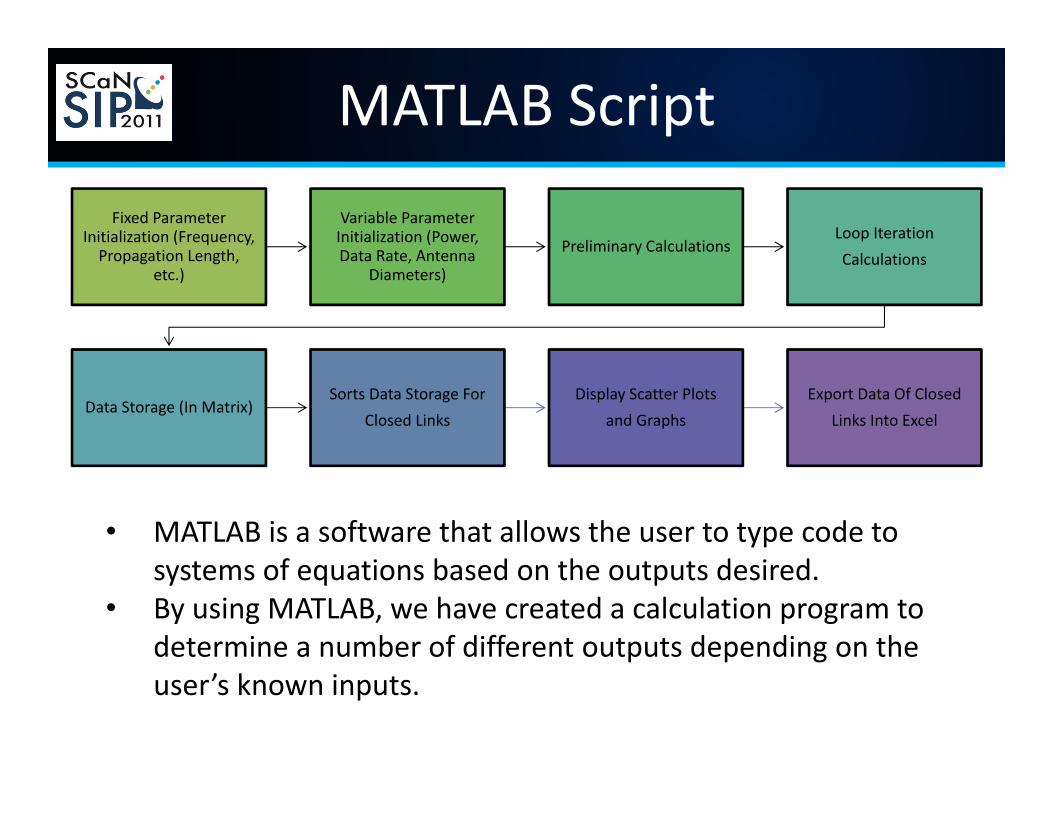
MATLAB ScriptFixed Parameter
Initialization (Frequency, Propagation Length,
etc.)
Variable Parameter Initialization (Power, Data Rate, Antenna
Diameters)
Preliminary CalculationsLoop IterationCalculations
Data Storage (In Matrix)Sorts Data Storage For
Closed LinksDisplay Scatter Plots
and GraphsExport Data Of Closed
Links Into Excel
• MATLAB is a software that allows the user to type code to systems of equations based on the outputs desired.
• By using MATLAB, we have created a calculation program to determine a number of different outputs depending on the user’s known inputs.

Data GraphsFrequency vs. Transmitter Diameter vs.
Transmitter GainTransmitter Gain vs. Transmitter
Power vs. EIRP

Data Graphs
Receiver Diameter vs. EIRP vs. Link Margin

STK Simulations• Satellite Tool Kit (STK) is a software tool that allows the user to
input the parameters while the equations are calculated by the software.
• To verify the results, we used the MATLab data to simulate the entire scenario in STK in a static environment.
• To provide a dynamic study of the environment for the link.

Static Environmental LossesSTK Results – MATLab Verification
Additional Constant Inputs:• System Noise Temperature: 300 K• Encoding Gain: 3 dB• Line Loss: ‐6• Modulation: BPSK
• Atmospheric Loss: 9 dB• Parabolic Antenna • Transmitter and Receiver Pointing Offset: Total 3 dB loss
Inputs: Frequency (GHz) Power (W) Transmitter Diameter (m)
Receiver Diameter (m) Data Rate (mbps) Outputs: EIRP (dBW) Eb/No (dB) BER
50 2.5 0.5 5 150 43.748 1.7574 4.17E‐0250 5 0.5 5 150 46.759 4.7677 7.17E‐0350 7.5 0.5 5 150 48.52 6.5286 1.36E‐0350 10 0.5 5 150 49.769 7.778 2.67E‐0450 12.5 0.5 5 150 50.738 8.7471 5.41E‐0550 15 0.5 5 150 51.53 9.5389 1.11E‐0550 17.5 0.5 5 150 52.199 10.2084 2.32E‐0650 20 0.5 5 150 52.779 10.7883 4.87E‐07
Max Data Rate of 236mbps at 5W for an Eb/No of 2.850 2.5 0.5 5 150 43.748 1.7574 4.17E‐0250 5 0.5 5 300 46.759 1.7574 4.17E‐0250 10 0.5 5 600 49.769 1.7574 4.17E‐0250 20 0.5 5 1200 52.779 1.7574 4.17E‐02
As Data Rate Doubles, Power Doubles50 2.5 0.5 3 150 43.748 ‐2.6791 1.49E‐0150 5 0.5 3 150 46.759 0.3312 7.09E‐0250 7.5 0.5 3 150 48.52 2.0921 3.60E‐0250 10 0.5 3 150 49.769 3.3415 1.89E‐0250 12.5 0.5 3 150 50.738 4.3106 1.01E‐0250 15 0.5 3 150 51.53 5.1024 5.47E‐0350 17.5 0.5 3 150 52.199 5.7719 2.99E‐03

Dynamic Environmental Losses STK Results
T = Transmitter, R= Receiver
Links A (50 GHz) B (55 GHz) C (60GHz) D (65 GHz) E(70Ghz) F(75GHz)
Components T R T R T R T R T R T R
Antenna Size (m) 0.5 5 0.5 5 0.5 5 0.5 5 0.5 5 0.5 5
Power (W) 3.54813 3162.28 1.12202*1020 446.684 1.99526 1.41254
Free Space Loss (dB) ‐217.7863 ‐218.6141 ‐219.3699 ‐220.0651 220.7088 ‐221.3081
Atmospheric Loss (dB) ‐1.2716 ‐31.4971 ‐197.7897 ‐24.498 ‐1.5219 ‐0.7529
EIRP (dBW) 51.269 81.597 247.853 74.548 51.692 50.791
Eb/No (dB) 12.2649 12.367 12.33 12.3168 12.4364 12.3044
BER 3.229566*10-9 2.138712*10‐9 2.486046*10‐9 2.622741*10‐9 1.60811*10‐9 2.756888*10‐9
V‐Band Analysis Summary
• Due to the extent of the atmospheric attenuation with V‐Band, the feasibility of utilizing the frequency band on a hosted payload between 58‐62 GHz is impractical.
• When constrained by hosted payload parameters, the power needed to transmit at these frequencies while keeping a sensible size ground station is unreasonable.
• At 50 and 75 GHz, the atmospheric attenuation is low enough for a transmission from space to ground with a high data rate. However, when using the rain model the loss increases such that the links do not close.
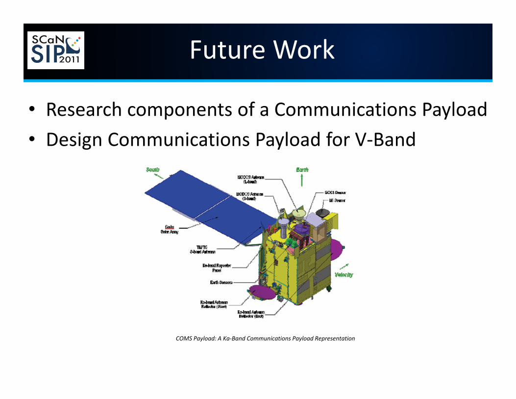
Future Work
• Research components of a Communications Payload• Design Communications Payload for V‐Band
COMS Payload: A Ka‐Band Communications Payload Representation

Questions?
Why don’t we just do optical?

References
• Books:– Digital Communications Fundamentals and Applications
• By: Bernard Sklar– Introduction to Satellite Communications
• By: Bruce R. Elbert– Space Mission Analysis and Design
• By: Wiley J. Larson and James R. Wertz
• Mentors:– Eric Knoblock, Systems Definition & Communications, DSE– David Avanesian, Systems Definition & Communications, DSE– Charles Niederhaus, Systems Definition & Communications, DSE– David Bittner, Systems Definition & Communications, DSE
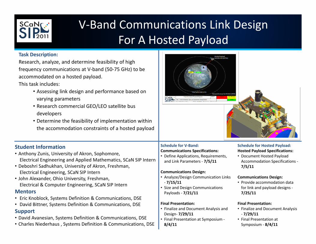
Task Description:Research, analyze, and determine feasibility of high frequency communications at V‐band (50‐75 GHz) to be accommodated on a hosted payload.This task includes:
• Assessing link design and performance based on varying parameters
• Research commercial GEO/LEO satellite bus developers
• Determine the feasibility of implementation within the accommodation constraints of a hosted payload
Schedule for V‐Band:Communications Specifications:• Define Applications, Requirements, and Link Parameters ‐ 7/5/11
Communications Design:• Analyze/Design Communication Links ‐ 7/15/11
• Size and Design Communications Payloads ‐ 7/21/11
Final Presentation:• Finalize and Document Analysis and Design‐ 7/29/11
• Final Presentation at Symposium ‐8/4/11
V‐Band Communications Link DesignFor A Hosted Payload
Student Information• Anthony Zunis, University of Akron, Sophomore, Electrical Engineering and Applied Mathematics, SCaN SIP Intern
• Deboshri Sadhukhan, University of Akron, Freshman, Electrical Engineering, SCaN SIP Intern
• John Alexander, Ohio University, Freshman, Electrical & Computer Engineering, SCaN SIP Intern
Mentors• Eric Knoblock, Systems Definition & Communications, DSE• David Bittner, Systems Definition & Communications, DSESupport• David Avanesian, Systems Definition & Communications, DSE• Charles Niederhaus , Systems Definition & Communications, DSE
Schedule for Hosted Payload:Hosted Payload Specifications:• Document Hosted Payload Accommodation Specifications ‐7/5/11
Communications Design:• Provide accommodation data for link and payload designs ‐7/25/11
Final Presentation:• Finalize and Document Analysis ‐ 7/29/11
• Final Presentation at Symposium ‐ 8/4/11
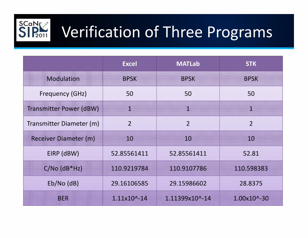
Verification of Three Programs
Excel MATLab STK
Modulation BPSK BPSK BPSK
Frequency (GHz) 50 50 50
Transmitter Power (dBW) 1 1 1
Transmitter Diameter (m) 2 2 2
Receiver Diameter (m) 10 10 10
EIRP (dBW) 52.85561411 52.85561411 52.81
C/No (dB*Hz) 110.9219784 110.9107786 110.598383
Eb/No (dB) 29.16106585 29.15986602 28.8375
BER 1.11x10^‐14 1.11399x10^‐14 1.00x10^‐30