Embed Size (px)
Citation preview

NATIONAL ADVISORY COMMITTEE .. . FOR AERONAUTICS .
TECHNICAL NOTE
NO. 937
SIMPLIPIED TRUSS STABILITY CRITERIA
By W. 3". Ballhaus and A. S. Nilis Stanford University
v!!!!! Tashington July 1944
RESTRICTED

BESTRICTED
ITATIONAL ADVISORY COMMITTEE FOR AERONAUTICS -1-1-e
TECHBICAL NOTE NO. 937 s---m
SIMPLIFIED TRUSS STABfLfTY CBETERIA
By W. P. Ballhaus and A. 5. Miles
SUMiARY
Part-I covers the development of simplified criteria for the stability of planar pin-jointed trusses against buckling in the plane of the truss, based on the earlier work of Viscovich. Part II constitutes a report on tests carried out to verify the validity of the criteria devel- oped in part I. The agreement between observed and pre- dicted critical loads was well within the range of proba-. ble experimental error.
This investigation, conducted at the Stanford Univer- sity, was sponsored by, and conducted with financial assist- ance from, the National Advisory Committee ,for Aeronautics.
I. GEi?ERAL STABILITY OIP PLANAR PIGJOIDTED TRUSSES
When designing practical trusses, an engineer seldom considers the general stability of the truss as a whele, and very rarely treats the stability of a single member as a function of the stiffnesses of those adjacent to it. Usually the conventional designaprocedures lead to truss designs which are stable, When, however, these procedure5 are used and it is found that the axial force computed for some member is zero, the calculated required area of that member is also zero. If such a member were omitted from a statically determinate truss, the structure would USU- ally bo unstable. Also when the computed axial load in a member is very small, the use of an area which has been computed by the conventional procedures may result in such a flexible member that the stability of the truss is impaired. In practice the experienced engineer will usually re,cognize such situations and use arbitrarily selected member sises, If he lacks a rational method of computing the necessary stiffness and must rely on ex- perionco,or intuition, he may use much larger sectional areas than are really needed. Since this would result
RESTRICTED

BACA TN No. 037 a
J
r
E
in unnecessary structural weight, a rational method of . attacking the problem is desirable. The first part of this report is devoted to the development of a simple and practical method for predicting the critical intensity Of loading for a pfn-connected planar-truss, with a simple and practicable design procedure for the rational design of the zero or slightly loaded members of a given truss configuration.
NOTATIOI?
cross-sectional area
modulus of elasticity .
spring constant
longth
axial load in link
work
axial load in supporting spring
external load on truss
angle of rotatfon or of deviation from nominal position
deflection parallel to original direction of link axis
deflection normal to original direction of link axis
ratio of lengths
The significance of subscripts and primes, and a few seldom-used symbols, is indicated where they are introduced.
PISCOVICR'S STABILITY CRITERIOH
Ike method of analysis presented here is an extension of-that developed by 6; Viscovich in reference 1. It will therofore be helpful to begin the development of the new method by a brief statement of Viscovichts method as it would, be applied in a specific problem, For this purpose

.
c
NACA TN Wo. 937 3
consider the truss of ffgure 1, for which the lengths and sectional dimensions of all members are assumed to be known. It is also to be assumed that the truss was SO cambered that, when the load W is applied at joint 8, the bars AB and BC .form a straight line. Then, according to the usual methods of stress analysis, the design load for member BE would be zero. If member BE were left out, the truss would continue to carry the load
2 B so long as joint B remained on the straight line
Because of the pin joint at B, licrium would be unstable.
however, its equi- It would also be unstable if
member BHf were too flexible to counteract any tendency of joint B to move away from the line AC. The problem is to determine the minimum stiffness requfred of member BE in order to obtain positive stability, or whether any specific stiffness of that member is in excess of such nfnimum.
Let the axial loads on the members produced by the load V at joint $ and associated reactions at B and F be called the Bprimaryn axEia1 loads. If member .AB is subjected to a unit couple while the truss is subjected to this primary load system, each member of the truss will rotate with respect to the line joining the supports. The magnitudes of these rotations may be computed by the . .- method of virtual work .or any equivalent procedure. The unit couple should be assumed to be so small that the angles of rotation, measured in radians, may be assumed numerically equal to their sines and tangents and that the cosines of these angles of rotation may be assumed equal to unity. The'rotations produced by the unit couple act- ing on AB will be termed the "unit rotations" and that for any nenber ,XY will be designated axy'
One effect of the unit rotations would be tb change the geometry of the truss and therefore to modify' the axial loa,ds.developed to resist the load Y at joint E. Since, however, it-is assumed that the unit couple and . the resulting unit rotations are small, such changes in tho primary axial loads may be neglected, Though these primary axial loads may be assumed unchanged in magnitude, they are not unchanged fn direction; but their lines of action have been subjected to the unit rotations. There- fore at each joint the axial loads on the members may be resolved into components parallel and perpendicular to the original directions of the members on which they act, The components parallel to those original directfons, P
XY cos a xy’ may be a,ssumed equal to the primary axial

.NACA TN No. 937 .4
.
loads, Px,. The perpendicular components, Pxy sin "xy, may 6imi1a;ly be a66Umed BQUal to %y"xy l
Sfnce the parallel components are equal in magnitude' and parallel to the primary axial loads found from the original truss analysis and the primary axial load6 are in equilibrium at each truss joint, the parallel components must be similarly fn equi.libri.um at each joint. Further- more, sfnce each truss member, XY, is designed to carry it6 axial load Pxy, these forces a&one would not produce fnstabili.ty.
The perpendicular components, .Pxy~,y, are induced by the unit rotations of the members and are therefbe termed the 6induced loads." In general, these induced load6 would not be in equilibrium at each joint but would cahse additional rotation6 of the truss member6 which may be termed their 6induced rotations.6 The magnitudes of the induced rotation6 can be computed from the inducad loads by the method of virtual work or any equivalent pro- cedure. :
Visoovich's stability criterion i6 that if the in- duced rotation of member AB is 106s than its rotation owing to the unit couple applied to it, that' member is in stable equilibrium: while if the induced rotation exceeds its rotation due to the unit couple, the equilibrium Of that menber is unstable. 1n.a statically determinate truss like that under consideration, if any member is fn unstable equilibrium, the whole truss*will be unstable.
Tn applying thZs criterion it is necessary to start with the assumption of a specific system of unit rotations produced by an arbitrarily located unit couple. Xor com- plete proof of the stability of a truss it would be neces- sary to investigate all possible locations for applying the unit couple, and the designer would have to apply it not only to each single member but also to each possible group of members, In fact, it might be necessary to assume several unit couple6 acting 6imultaneopsly. In practice, however-, very few of the theoretically possible unit rotation systems need be investigated, and the crit- ical ones are easily identified. Thus for the truss of figure 1 the investfgation could bB limited to determining the effect of using too emall. a cross-sectional area fdr member BE, and applying the unit couple to member A.3.
,

WACA TD No. 937 5
Tfnless some member is present for which the design axial load is much smaller than those of its neighbors, the resulting design sizes are large enough 60 that if * each is capable of carrying its design load there will be little danger of general instability of the truss. The stability of members adjacent to an unstressed or very lightly. loaded member, however, may be impaired through failure to assign sufficiently large sectional dimensions to the'latter. The designer's problem is therefore to ideltif:* these "critical" members, assign sectional area6 to them, and then.to make sure that the adjacent member6 have been made stable.
If different Size6 are assigned to the critical mem- bers and Vfscovich~s criterion is applied to each size, the engineer may thU6 investigate the adequacy of his de- sign. !I?his criterion, however, indicate6 only whether an assumed size for the critical member is sufficient to - provide Stability. To obtain the most efficient desfgn, uevoral trials may be needed, 6inee Viscovich failed to ' develop a procedure for the direct determination of the size of lightly loaded member needed for Stability. If his method were short, simple, and free from abnormal hazards of calculation error, it would be acceptable in practice. The opposite is true, horrever,‘and the method, as developed by V-iscovioh, is not suitable for ;practfcal de6 ign work. The desirability of a sfmpler method for tho rational design of 6unstre6sedn members and prediction of the Stability of pin-jointed planar tru6688, has led t0 tho ostonsion of h%s procedure that fs developed below.
STABILITY 03' SYSTEMS OF ELBSTICALLY SUPPORTED BARS
The stability of a pin-connected truss may be deter- mined by suitable application of the stability criteria of a small number of type systems of elastically supported, absolutely rigid, pin-oonnected lfnks. In fact, only three such system6 are needed for handling almost any stat- ically doterminate truss pattern, and the fir6t Step iS to devolo?', the stability oriteria for these three systems.
“r The first to be considered is that shown fn figure 2 whore an absolutely rigid link AB ia connected to a
. z rigidly supported frictionloss pin at 8, and is supported at B by the elastic member BC which has a spring con- stant K. The lwver end of BC is connected to a rigidly
0
BZCA TW No.. 937 6
supported pin at C. It is assumed that the load P is applied horizontally to the originally horizontal memb8r AB . TLmoshenko has shown (reference 2) that the critical value of P for this SySt8m would be .
l
c
P cr =Ks,
An equivalent statement is that the critical value for the spring constant K is
K P cr .= E
(1)
(2’)
The second system to be oonsidetied is that shown In figure 3. Here the rigid links AD and ZC are supported at A and C. The support at A is assumea completely restrained from movement in translation. IPhat at C is restrainsd against vertical motion, but 18 free to move horizontally. There is no restraint against rotation at either A or 0. At B the two links are -joined by a frictionloss pin which is supported by the elastic membor BD of spring constant K, By extending to this system the method used by.T'imoshenko to analyze that of figure 2, Viscovich showed that the critical value of the spring con- stant K would be .
K cr 7 ---+---
and if the axial load is the same for'both links, its critical value would be
P ' Lab Lbc cr = z------- ab + Lbc
(41
The thfrd system to be analyzed is that of figure 4 where the rigid link AD elastic members
is supported at its ends by the
and IC.2 I AC and BD with sprfng constants K,
respectively, Viscovich analyzed this system, ' assuuillg the axial load P in AB to be constant, and found cs the criterion for stability
(5)

NACA SB Wo. 937
From this r-elation, if Ha and P are specified, the critical value of K2 is
K2cr= 4 K1 P K,L-P
(6)
In extending Viscovichls work it will be assumed that the axial load P, instead of being constant, varies linearly from PI at A to P1 +sL‘x at any pofnt X at the distance x from A. In studying this system it is convenient to measure the movements of all points along AB. with respect to vertical and horizontal axes through A. In effect this is equivalent to replacing the system of figure 4 by that of figure 5, but this -is allowable since the stabflity criteria for the two systems are identical.
Assume the link A8 to rotate through the small angle ci, the centor of rotatfon being any point E along its length. The resulting horizontal movement of any point X at the distance X from A would be
.
yx = x vers a 0)
ff the angle a is small, and it is so assumed, -vers cc is apProximately equal to a8/2, whence
Consider now a differential element of the link AB with its left end at X. Shis element and the forces .aot- ing on it are shown in figure 6, in which the upper portion reprosonts oondftions before, and the lower portion condi- tions after, the assumed rotation through the angle ctB 20 satfsfy the conditions of equilibrium
PI + px + lbdx - PI -‘p(x + dx) - 0 (9)
c
.
As a result of the assumed rotation, the left end of the clement would move horizontally -through the distance YX end the right en@ through the distance Y, + dx' The work dono by the horizontal forces acting on the element w0d.a tbOr of 0r 0 b0

BACA TN Bo. 937 ‘8
+ [ p, + P(X + ax) I $ ix + ax) (10) Combine torms and neglect second-order differentials, and this bocones
au, = $ cq ax + px ax)
Sanco, however, the angle a has been assumed small, it may be represented by
61+ 82 a = --r-w- II
(12) .
whence
due = h1 + a2j2
----g--- (PI + yxbx (131
The total work done by the horfiontal forces on the link can therefore be found by integration to be
Since P2, the axial load at B is equal to PI + PII, FL can be replaced by (Pa - P,)/L and equation (14) becomes
u, = (61 + 6212
4L -- (PI + pa> (15)
The total strain energy stored in the springs as a result of their elongations 8, and. 62 is
El6 1 2 K262
2
- ui = -T- + -- 2 06) ,
According to the energy theory used by Timosheako, the critical loading is that at which We = Ui, Equating the expressions for those quantities and simplifying gives
.
NACA TEN lo. 937 9
W12 2 (81
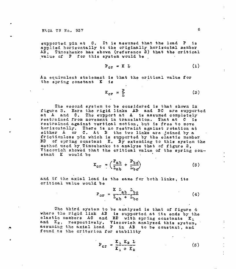
+X,82 =- +$"'f (Pr + P2) (17)
In order to satisfy the requirements of equilibrium, the tension in one of the elastic members supporting the link AB must be equal to the compression in the other. If this force is designated by V, e1 = V/K, and 82 = V/K,. If these values far the deflections are in- serted in equation (17), it may be simplified t0
p1 + p2 Ef, K2 3--c = - L (18)
2 K, i--It,
If the axial load is constant, the left side of equation (18) nay be replaced by P and that equation becomes identical.wtlth equation (5), checking Viscovich$s result. Thus Viscovfchfs stability criterion is valid for a lin- early varying as well as for a constant axial load in the link if the average axial load is used for P.
In the above development of stability criteria, the links were assumed perfectly rigid -r that is, knextensi- ble, The criteria found are equally applicable, however, to extensible links, since it is assumed that any virtual rotations of the links take place after the axial loads have been imposed and that those*loads, and consequently the link lengths, remain unchanged during the rotations, A slight error may be introduced as a result of the axial load being changed by the rotation, but as long as the rotations are small, such errors would be negligible.
SIIJPLIPIED TPBUSS STABILITY COMPUTATIONS
In applying Viscovich's procedure for determining the stability of a truss the entire structure must be dealt yrith simultaneously. The simplified method pro- posed here is to isolate and analyze small portions of the truss, each including a member which is of such light construction as to make the stability questionable. These isolated portions would be treated as if they were systems of the types analyzed above. Thfs involves assum- ing rigid support for the pins at which the isolated por- tion is attached to the remainder of the truss, It will be coi:veitient to illustrate the application of the

I .
'NACA TN No. 937 -19
procedure before attempting to demonstrate the validity of this underlyfng assumption.
If the section of a pin-jointed truss'shown in fig- ure 7 is loaded as shown, no axial load will be imposed on member BC. Ifember AB, however, will be subjected to an axial compression, 'ab* equal to the external load
wb* If joint C is'assumed rigidly supported,'members AB and BC form a system of the type shown in figure 2, the si:Olilarly lettered members are equivalent to each ' other. The critical, or minimum allowable, spring con- stant for member Bb will therefore be Kbo = ?ab/Lab* The practical design problem, however, is to determine . not the critical spring constant, but the minimum allow- able size for member BC, If,that member is assumed to be elastic, its elongation under load is obtainable from the relatibn
(19)
.
where AL is the elongation, L the original length, P the axial load, A the cross-sectfonal area, and E the modulus of elasticity of the member. Since the spring constant or "stiffness" of a member is the ratio of its axial load to the resulting elongation, for any member
K=&+ AL
cm .
The critical value of the spring constant of member BC is therefore
from which the minimum allowable value for the sectional area of BC; is
P 'bc = abq
%C
where q fs the ratio Lb cl Lab *
(22)
The sane basic method can be used to deternine the

NACA IN Uo. 937 11
. required sectional area of menber BE of the truss of figure 8 for the loading shown. For this example the type system to be used consists of members AB, BC, and By s which is equivalent to the system of figure 3. In this cask, since the truss and its loading are symmetrical, equation (3) for the critical value of the spring constant when applied to nenber BE, becones
t
3
2%! %o = Lab Combination of this expression with equation (20) and solving for Abe gives
2 %a Abe"w~e n
where v is the ratio heiLab*
ACCURACY OF THE SIMPIIIFIEP ME'L!XOD
(23)
(24)
88 previously mentionep, this simplified method of investigating the .stability of a truss is based on the assumption that the pins connecting the isolated portion to 'the remainder of the truss may be assumed rigidly supported. Since completely rigid support is impossible, the effective spring constants of the members assumed elastic are somewhat less than those computed from equa- tion (20). While it would be difficult to develop a gen- eral proof that the resulting error in the computed areas required for these members would be negligible in a rea- sonably well designed practical trus8, it is not difficult to show that this would probably be the case.
In the foregoing discussion the pofnts at which the systea under consideration were supported were assumed tp be rigidly supported. An alternative is to assume that each such point is elastically supported, alid to define as fhe "spring constant of a points the ratio of load imrJosed 3n that point to the res%lting movement of the point saralIe to the line of action of the load. Each point therefore must be assumed to have two spring con- stants , one based on its movement under vertical and the other based on Its movement under horizontal force, and
HSC-4 TN No, %7 12
these may be termed its vertical and its horizontal sprfng constants, respectively.
The criterion for the required area obtained for member BE of figure 8 implies vertical spring constants of infinity for points A, C, and E. It should be com- pared with the criterion which would be obtained if the spring constants of those point8 were reduced to values which would be associated with reasonable selections for the dimensions of the truss members? In the appendix the analysts ol a truss like that of figure 8 is summarized. In selectfng'member sizes for this‘truss an allowable working stress of 30,000 psi was assumed for the tension members, and the Euler 'formula was used for the design of the compression.members, whiah were assumed square in cross section. The sectional areas having been selected, the next step was to determine for eaqh member its value of WE * termed by J. Clerk Maxwell its "extensibility" (reference 3)*. Kor this step E was taken as 30,000,OOO psi. Once the extensibilities of the members had been determined it wa8 a simple matter to compute, by the method. of virtual work, the vertical deflections of joints A, C, and B that would be produced by unit vertical load8 im- posed at those joints. The vertical spring constants thus determined were Ka = I,‘= 158,591 pound8 per inch and Ke = 106,400 pound8 per inch.
This procedure included no basis for the desfgn of member BE. According to the simplified stability cri-
. terion described, however, the minimum allowable spring
constant for th&t member would be 2p,b= 2 x 30000 --- = 666 I'ab 180
pound8 per inch. Member BE was therefore assigned the sectional area needed to produce this value.
In the development of the simplified criterion for stability the group of member8 converging,at B was assumed equivalent to the system of figure 3. For the more accurate investigation It is assumed equivalent to that of figure 9a, where members AB, BC, and BE are elastically supported at A, C, and E by Springs which have for their effective stiffnesses Ka, .Kc, and K e' respectively, Member BE is assumed to have the --- ---Iy-p--mT----L-c----------
*It is to be noted that the extensibility of any member is the reciprocal of $.ts stiffness or spring con: stant.
XACA 'TB Bo. 937. 13
effective stiffness Kbe = 666 pounds per inch as calcu- . lated.
This equivalent structure requires further simplifi- aation in order to develop a satisfactory criterion for its stability, From inspection of figure 9a, bearing in mind that the conditions of equilibrium must remain satis- fied, it can be seen that if points A and C move upward when ABC is subjected to a horizontal load, points B and E must move downward, In the system under consideration K, = Kc and the vertical movements of points d and C would be equal. If the deflections are measured with respect to a line through 9 and C instead of one through the suppbrts, the system of figure 9b may be used in place of that of figure 9a. In this substitute structure the members meeting at 3 are sup- ported by a fixed pin at A, a vertically fixed pin at C and a pair of springs at D, one with a spring con- stant equal to Ka and the other with a spring constant equal to Xc, This pair of springs in parallel may be combinad into a single spring of stiffness Ka + Kc, which in this structure would make its spring constant equal 2 Ka. This modification is represented by figure 9c.
Zhe spring BD and the spring between D and the fixed foundation act in series, the first having as its spring constant Ke, and the second 2 $a, The effective spring constant of the combination - that is, the- spring constant of point E with respect to the foundation - will thenbe (reference 4)
(2 Q xe p;, = v-w- ---- (2 Ka) + Ke
and for the specific truss under study
(25)
Xl * -- 317000 X 106000 .- = inoh 317000 + 1'06000
79,400 pounds per .
Fhis effective s‘ystem is 'represented in figure 9d. S ini- larly the effective spring constant of point B can be found from

NACa TN No. 937
‘
which gives
Kb = 'be '1 ---w-- ICbe + Kl
(26)
666 x 79400 '?' = &6 + 79eo:
= 660.47 pouids per inch
Thus the effect of neglecting the elasticfty of the sup- ports of joints A,- C, and E results in an error of only 666 - 660.47 = 5.53 pounds per inch or 0.837 per- cent.
Although the error resulting from the application of the sin:>lified criterion to the truss of figure 8 is less than 1 percent, this is not a proof that such errors will be.comparably small for all praotical trusses. If, in practice, it were proposed to use an unstressed member with a spring constan% little if any larger than that called for by the simplified criterion a more refined analysis similar to that made in this section would be *in order. In praotice, however, it will nearly always be found that the size required to satisfy other conditions, such as those of handling, will be so much larger than that called for by the simplifted criterion that the in- herent error due to the simplification may clearly be ignored.
DFPiJCT OF DEVIATIONS FROM NOMIKAL TRUSS DIMENSIONS
. The required stiffness of a uritical member as cal- culated Fn the preceding sections is the minimum required for tho stability of the truss under the loading consid- ered. Plhile these calculations were based on the assunp- tfon that the truss would be geometrically perfect, that would never be the ease in a practical structure. A coaploto investigation into the problem of stability of pin-jointed planar trusses must, therefore, include a discussion of the effects of deviations of the actual from the nominal truss dimensions upon the validity of the calculations or, tf more convenient, the inclusion of the effects of suah deviations directly in the oomputa- tions.
If the truss of figure 10 is assumed to bo manufac- tured to a given degree of accuracy, the effects of

RACA TN No. 937 15
deviations from the nominal dimensions would be to make the angles ABE and CBE differ slightly from their nom- inal value of 90'. It can also be seen that if the truss were orig;inally designed without camber, the loads coming on to the structure would cause an additional deviation
,from 90° of the angles ABE and GEE. Furthermore the use of initial camber could eliminate this a.dded angle of deviation for but one loading condition. As the load at E is increased, the angles ABE and CBE will change accordtng to the increase in the load. Thus the total deviation of the practical truss from the ideal truss pre- viously considered may be represented by the totalcdevia- tions, a0' of the angles ABE and CBE from 90 , caused by rotatfoas due to the elongations of the members under load and deviations in manufacture from the nominal dimensions. The angle a0 will be termed the initial angle.
For any given value for the initial angle, it is pos- sible to design the entire truss, including member BE, by the usual methods of truss design. The relation for finding the axial load on member. BE is
Pbe = 2 pab a0 (27)
ABE and QBE are not the only.angles that would be affected by the deviations of the actual from the nominal dimensions, but it should be obvious that members like BE s which would be subjected to no load if it were not for such deviations, are the only ones where the percent- age change in axial load due to the deviations would be appreciable. .
After the magnitudes of the inlitial angles have been decided upon and the axial load on BE has been computed by the usual methods of truss analysis, the sect‘ional dimensions of that member may be obtained in the usual manner. In the problem at hand, if the allowable working stross for BE is cWt the required sectional area for that member will be
.r
.
2 pab a~ -w---w-- Abe = d w
(28)

NACA TN No. 837 16
Essentially, the calculation of the required stiff- ness for BE in the ideal truss by the simplified sta- bility criterion may be interpreted as a computation of the minimum area for BE consistent with stability, Bquation (24) may be rewritten,
Abe = -ii-- 2 Bab rl (24)
Thus tao ,separate criteria are obtained for the design of member BE. In equation (28) it can be seen that the .re- qufred area is directly proportional to the load in AB and the angle QO) and inversely proportional to the working stress Uw. In equation (24) the required area- of member BE fs directly proportional to the load in
AB and to the ratio q, and is inversely proportional to the modulus of elasticity of the material. Bor differ- ent trusses and different materials it is obvious that first o!le, and then the other criterion might yield the larger value for the minimum allowable sectional area for member BE. Naturally, the criterLon calling for the larger area is that which should be used in design. It is therefore desirable to develop a convenient method for choosing the criterion to be used in any specific design. problem.
If the areas from equations (24) and (28) are set equal to each other and oto is plotted against aw/E: I the relation may be represented by a family of straight. lines through the origin, one for each value of q. A diagram of this type is given in figure 11. If the point ho, cr,/E) lies on the line for the associated value of rl, the areas computed by the two criteria will bc the same. If that point should lie above the line for the associatcd.value of n, the initial angle criterion will yield tho larger area: while if it falls below that. line, the singlified stability criterion is the more scvero* $igure 11 can therefore be used to determine the criterion to be emgloyed in the design of a truss like that of fig- ure 10,
If the effects of an initial angle upon the design of a member such as BC in,figure 12 are to be invosti- gated, it can be seen that the support at A may bo taken as fixod. The total effect of tho deviations of actual from nominal dimensions may be reduced to a singlo small acute angle betvoen member AB and the vertical.

NACA TN No. 937 17
’ c
. If this angle is designated Q.~, the usual method of truss analysis yields for the minimum allowable sectional area of member BC
P Abe =
ab ao QW
(29)
where Abe is the required sectional area of member BC, P is tho axial load in AB, and QW is the allowable working stresa for member BC,
The simplified stability criterion for an ideal truss of this type is given by equation (21) and the area com- puted from it is
.
t
where rl is the ratio Bbe/Bab. . If equations (29) and (22) are set equal.to each
other, the relations between aor a& 8 and s( will be represented by figure 11, though that figure was Originall'y
drawn up for a diffsront truss pattern. Figure 11 can therofore be used in the design of a truss like that of figure 12 in the same manner, as in that of a truss like the one shown in figure 10.
The method of investigating truss stability used in developing the criteria of this report differs considerably from that proposed by Van Hises and Batzersdorfer in refor- ence 5. It would be of interest to compare the results of applying these alternative methods to so.me spec_lfic truss designs. Limitation 'of time and personnel, however,"pre- vented the inclusion of such a comparison in this report. '
II. EXPEBIZENTAL INVESTIGATION OF TRUSS STABILITY CRITERIA
Since no theoretical formula should be relied upon until its validity has been established by tests, the second part of the investigation covered by this report was devoted to the construction and the testing of a small pin-jointed truss to determine its actual critical load. The truss used was of the pattern shown in figures 1 and 8, the unstressed vertical BE being so designed that its

MCA TX NO. 33-7 18
stiffness could be varied over a considerable range,
Originally it was intended to compare the observed critical loads for this truss with those computed by Viscovich*s criterion. While the computations to deter- mine suitable sizes for the truss members were in progress it became evident that Viscovich's procedure was too com- plicated and tedious for practical design, It was also noticed that the differences in calculated extensibilities between.those for unstressed verticals likely to produce instability and those of the other members were very great. S,tudy'.of the formula for the effective spring constant of .two springs in series (equation (26)) indicated that for practYca1 purposee it would be reasonable to treat these differences as if they were between finite and infinfte quantities. Thus if K is the effective spring constant of a pair of springs in series, one with a small spring constant II, and the other with a very large spring con- stant Ka, and K,/Ka is assumed negligible in compari- son with unity,
K= ALK, = ALL K,+,Ke l+%
= K, (30)
The sinplified criterion was therefore developed as de- scribed in part I of this report.
Had Viscovich's criterion been used for determining the thooretfcal critical load for the test truss, it would have been necessary to determine the extensibility of each member. The development of the simplffi.ed criterion -de this suyorfluous for all except the unstressed vertical, but it was decided to determine the extensibilities of all the members in order t'o have as complete information as possible on the properties of the test truss. Te-sts were therofora made to.obtafn three types of data: extonsibil- ities of members subject to finite primary stress, stiff- nesses of the member used for the unstressed vertical, and critical loads for the truss, This part of the report is the record of those tests. ,
TEST &ATERIAb
b The test specimen was a truss, of the pattern shown
in figures 1 and 8, which was specially desi ned for the purpose. The tension members were l/16-by 3 36vinch

NAOA. !Pii X0. 937 19
annealed tool steel and the compression members w8r8 7/32- by ?/32-inch square polished drill rod, or 7/32-by 7/32- inch square cold rolled steel. Thus al& the materials were conparat,ively soft, and easily machined to within 0.001 inch of nominal dimensions.
If the truss joints are lsttered as in figure 8, joints +A and D are located symmetrically to joints 0 and F about the midplane of the truss. The joints were so constructed that th8 resultant loads on the individual truss members wer8 within about 0.001 inch of being co- planar and acting along the centrofdal aX8S of the members, This was true although th8 members w8re not actually con- n0Ct8d t0 Sing18 pins at joints A, G, and 1. Figure 13 shows the truss a,sSembled. liguresl4 and 16 show the con- struction of joint 0 in detail. Figure 16 shows joint D, and figure 17 shows joint B. Figure 18 shows joint E: assembled and figure 19 shows the same joint with one of the plates r8mOv8d.
The unstressed vertical, or critical member BE of figure 8, was so constructed that the axial stiffness could be vnrled, This member had tWo main elements, as can be s8en from figure 20. bent 90’
The principal element was a steel rod in two places to form a letter IT. The other,
called the spacing bar, couldbe set to produce a stiffness for the c.ombination of almost any value fr?om 2 pounds per inch u2 to about 70,000 pounds per inch, The u-shap8 element was made of l/16-by 3/16-inch annealed tool steel. The spacing bar was made of 7/32-by 7/32-inch square pol- ished drill rod. 9 loop of St881 was provided Over each end of the spacing bar, so that the legs of the U could be clamped against the ends of the spacing bar by set screws whfch were located in these loops. The outer sur- faces of the legs of the U were center-punched at equal intervals so that.the conical ends of the set screws could fit snugly into the conical center punch marks. After a stiffness had been determined for a certain set of corre- sponding center punch marks, it was always possible to r8- ga9n that same stiffness by fitting the set SCr8WS into the same two marks. Thus it was possible to repeat exper- iments without remeasuring the stiffness of the member aftor each setting.

. BllCA TB PO. 937 ’
TEST APPARATUS
20
Apparatus for Measuring Extensibilities
Figure 21 shows the apparatus used for obtaining th8 extensibilities of the tension members. A 3-by 8-inch steel I-beam was erected with ths outer face of one flange vertical, and a trUSSed cantilever bracket was bolted to its upper end. A fitting which was drilled and slotted to accommodate the l/16- by 3/16-inch members of the truss was bolted to the free end of this cantilever bracket, . The tension members were hung directly from this fitting and a similarly drilled and slotted fitting was provided at the bottom end of each such memb&, Prom a milled knife edge in this lower fitting there was hung a U-shape link of l/Pinch steel rod which tended to reduce the flexural rigidity of th8 system. A l/2- by l/2-inch square piece of steel 2 inches long was drilled along a diagonal and held on the U member with a nut on each leg of the U., This acted as a sort of knLfe edge which supported a steel wire of about 3/64 inch diameter that was strung over it. The lower 8nd of this wire supported the weight pan. Thus there were a total of four joints, which tended to elimi- nate almost all flexural rigidity of the load-applying sys- tem. Load was applfed directly to the wefght pan. Thus, except for an extremely minute amount of flexural rigidity, the tension load was applied vertically and axially to each member.
TWO optical mfcrometers or mi.CrOSCOp8S, graduated to read to 1/28OOC inch, were clamped to a piece of l$- by l*- by l/4-inch steel angle and were set at a distance equal to the axial distance between the pins at the ends of the mem- ber being tested. This angle was supported by a structure independent of the r8'St of the apparatus 60 the loads on the specimen would not affect the distance between the microscopes, Under the usual increment of the load, about 25 pounds, the specimen as a whole moved measurably, due to the flexibility of th8 cantilever bracket. Thus if readings were taken from both micromkters at z8ro load, the total elongation for a given load would be the movement read at the bottom microscope minus the movement read at the top microscope.
When the square section compression members were tested this apparatus was modified, as shown in figure 22. The member was hung from the cantilever bracket end fitting

.
. KACA TX MO, 437 21
by a short piece of l/16- by 7/32-inch stock which fit into the nllled slots in both the fitting and the member tested. The lower slotted fitting was connected to t'he lower end of the member by another short piece of l/16- by 7/32-inch steel which fit into the slots of the fittdn& aad the member tested. The other parts of the apparatus were the same as in the tension member tests. Tensfon loads were applied to these members, Young's modulus for tension and compressfon being assumed equal.
Agparatua for Measuritig 6tiffness of the
Unstressed Vertical Member
The apparatus for measuring the spring constant of the U-shape member is shown in figure-23. The and of one leg of the U wag. rigidly supported against horfsontal movement by a thick cast iron block and was supported ver- tically by a small steel. block. 5 The cenBer of the bottom of the U was set on a small hard steel roller which rested on a hard @tee1 block. The end of the other leg of the U also rested on a hard steel roller. The rollers eliminated al.most all friction, The lJ was supported at these three points so that it lay in a horizontal plane,
The load was applied vertically to a weight pun, and was tzansaitted throtzgh a flexible string over an aluminum ball bearing V sheave to the horizontal direction. The top of the V sheave was set in the came horizontal plane as the U spring,
An optfc&l micrometer, calibrated to read 0.000267 inch >er division, was set over the end of the free leg of the U spr'ing. Since ft was assumed, for the small loads applied, that fhe end of the leg which bore directly on the cast iron block did not move at all, the measurement of the movement of the end of the free leg was taken as the change fn distance between the two ends of the legs.' The ratio of the load applied to the deflootion observed was taken as the effectfve stiefness of the member -BE.
TrussdTesting qpparatus
As the truss had rather small dimensions in a lateral direction, it was evident that it might become laterally unstable before beooming unstable in its plane. Since the

MtCA TN No. 987 22
objective was to'determine its stability in its plane, it was necessary to provide lateral support. As shown in figure 13, a rectangular steel plate l/2 inch thick was supported at each end of the bottom edge so that the longer edge was horizontal and the facg of the plate was in a vertical plane. Two 120° V grooves v?re cut in the top edge of the plate, 24 * 0.003 inch apart. Two machined and case-hardened knife edges were set into these grooves. A IO-inch long bar of 3/4- by 3/4-inch cold rolled steel hung from each knife edge and lay against the face of the plate. Theso bars hung vertically and gave the effect of having one end of the truss simply supported and the other on
I rollers, since they could rotate slightly as the truss de- formed under load. Slots 7/32 f 0.010 inch wide were milled in the lower ends of these bars to accommtidate the ends of the truss and to allow sufficient clearanoe for Tree movement of the 7/32- by ?/32-inch truss metiers. Holes were drilled in the bars the same sise as the pins in the onds of the truse members& -Each end of the truss was set in the milled slots and held there by the pins. A piece of 0.005-inch shim stock 7/32 inch in diameter was placed on each side of the truss member and drflled so that the pin 4eld each.shim in place. This assured clear- ance between the 7/Z2-inch truss members and the material on ei$her siaa of the 7/32--u O.OlO-in& slot,
A brass lateral support was provided near each of the upper ends of the outside diagonal members. A single lat- eral support was provided jus$ to the left of the center pin joint in the upper chord. Since this support had to have as low a coefficient of friction as possible, two knife edges of tool steel were made "dead hard" by heating and quenching without subsequent drawing. They were then polished and supported by brass fittings. 'The knife edges were spaced to give 0.001 inch-clearance for the upper chord member which moved between them. Thus- the entire truss vita laterally supported at five positions, this be- ing the minimum number for a truss having such configura- ti.on an& loading conditions. The frictfon forces caused by these lateral supports was very small compared to the loads in the truss members, and was ignored.
Two adjustable stops, clamped to the vertical plate which laterally supported the truss model, were provided above and below the upper chord members to prevent them from rotating through too great an angle while the truss was under load, The upper stop consisted of the spindle and thimble of a micrometer; the lower stop was tbe
XACA !rE x0. 937 23
. rounded end of an extra-fine-thread'screw.. The total MOveLle.ilt of the portion of the upper chord between these stops could be measured to ~0.001 inch by reading the micrometer and then turning the thimble until the spindle pushed the member into aontaat with the lower atop. Light from a emall flashlight was reflected from fhe sup- porting plate through the gap between the contact points of the stops and the horizontal member which moved vertf- tally between them. In this way the first 0.0006 inch of movement of the member away from the stop could be ob- served,
TEST PROCEDUBIS AND RESULTS
Determination of Extensibilities
Each member was tested in dfreat tensfon while sup ported in the apparatus described. The weight pan and fittings between it and the lOW8r end of the member tested were the only tare loads on the members. A reading of each optical micrometer was taken at zero load and at all subsequent Zoads. The usual load increment was 25 pounds and the usnal maximum load was 150 pounds. There were, therefore, six points at which load and elongation were observed. The elongatson was plotted agafnst the load for each member .and the slope of the straight line drawn through those points was then taken as the extensibility of the member. Four of these load-elongation curves, one from each pair of symmetrically located members, are shown in figures 24 and 25.
The extensibility of each member was measured in this manner at least twiae. For eaoh member the agreement bo- tween the measured extenslbilities was within 2 percent. With each pair the difference betweeh'the average measured extensibflitfes for the individual members was less than the spread of the measured extensibilit~es for each of the pair. The average of all :the measured eJ.%qreliilities ob- tained from tests on both members of a ps.ir W'L therefore taken as the extensibility of both of thuae members; The extensibilities thus obtatned were: for menbers AR and BC, 8.9 x loo6 9.30 x lo-=
inch per pound: for AD and CT ) inch per pound; for Al and ea 36.43 x lo-
inch ner pound; and for DE and EZ', 39.82'X loo6 inch per pound.

RAtiA TX No. 937 24
L
Since the.measured elongations were the changes in distance between the pins through the ends of the members and were affected by the sudden changes in section near those ends, no attempt was made to obtain a close conpar- ison between the observed values and values computed from the dimensions of the members and an assumed value for YoungIs modulus. Approximate calculations, however, showed that the observed elongations were of reasonable magnitude. The spread of 2 percent between S8pWat8 tests of a single member is assumed to be an effect of fmperfec- tioue in the test apparatus rather than a measure of devi- ations from some assumed ideal nominal dimensions, It is of interest to note that this spr'ead between the meaSUr8d extensibilities of individual members is considerably greater than the computed error in the critical load'for the truss investigated in part I of this report. This is one of the factors which justifies the use of the si~plf+ fied crfterfon instead of the more precise but more ' tedious criteria for which it is offered as a substitute.
Determination of the Stiffness Of the U Member BE
The stiffness of the U member was measured with the spacing bar at each one of the five sets of center punch marks in the legs of the principal element. The set screws at each end of the spacing bar were tightened into corressouding center punch marks and the entire member was placed in the apparatus for measuring the deflection of one leg with respect to the other with each incremenSl of load, For each increment of load, usually an Ounce, . the iscremer?t of deflection of the free leg was observed throuGh the optical micrometer and readings of load and
- deflootion w8r6 reoorded. The set screws were.then loos- ened, the.spacing bar was moged,to the next set of corro- I spending center punch marks, and a new 'set of deflections and loads was recorded. This prooeduro was repeated five times tnd the results of the observations are plotted with . load versus deflection. The experimental spring constant then is tho slop0 of the loading-dsflection curve. The five curves obtained are shown in figure 26.
After having gone through a series of tests to dotor- mine tho spring constants, the procedure was completely . repoa%od to determine whether the assumptioti that the spring constant would be the same aftor changing tho sl,%c- ing bar*8 position actually was j.ustifiable. It was found by these check tests that the observed valwes of the
.

spring canstants changed negligibly when the spacing bar was taken fr,om one set of center punoh marks and then ree turned to the same marks after other tests upon the I,? member had been completed.
Dotornination of the Critical Load for the Truss
For dotermining the crftiaal load for the truss it was first assembled and placed in the testing apparatus. The offocts of friction in %ho joints wers investigated and it was found that, when the trU$S was Oaref'ully * loadod, Sf the upper chord members were CarefullY alincd after oath increment of load and there were no vfbratfons or other disturbing forces, the truss without the center vertical could be loaded up to the ultimate for the mato- rial used, %!he ability to aarry such load in this condi- tion was duo to tho vary acourate alinem?nt of the thrco pins in the uppor chord mombors and the small amount of friction in the pin joints. Although it was possible Par the truss to be in equilibrium without the center v8rtd- aal, the structure was not stable in this condit.ion.
Ifhen a structure liko a truss ia subjected to load and is doformed to a configuration fn which all foraes are En oquilfbr ium, that oonfiguratloa may be termed the equilibrium configuration for tho given loading. The stability status under thoso conditions dopsnds on what hapDons when fho configuration is. slightly modified. Tf there is a tondoncg to roturn to the equilibrium confie uration, the equilibrium fs stable; if there is a tendency to ranafn in the now configuration, the truss is in neu- tral equilibrium; and if the change in co&figurat%on tends to become more pronounced, the 8quilfbrfum is unstable. The tondenoy regarding roturn to the equilibrium position fs a function of the load in actual structureS and, as the load on a structure fnorea6e8, the tendency to return de- W8aSo6 until it changes into a tendency to deflect fur- thor. The load at which the tendency to return to tho equilibrium posftion dfsappears is taken as the critical load. In these tests only this tendenay to return to the equilibrium could be investigated.
.
112 each test the u member was adjusted to a giV8n stiffness and thon was plaoed in the truss. The truss was noxt loaded to within a fow pounds of tho critical load Calculated for the stru@turc by the s$mgliffed sta- bility criterion. The upper chord member6 were then so

VACA TN No. 937 2G .
rotated by hand that the center pin joint connect%ng these members was moved vertically 0.030 inch in each direction from the mean equilibrium position, the top and bottom stops having been adjusted so that the rotations could not excired these values. This involved a rotation of -the mem- bers of about *0,005 radian. When the members were rotated . while the load on the truss was below the calculated crit- iFal load, a perceptible amount of spring back from the stops was observed. As the load was increased, the amount of spring back decreased: and ,when the spring back com- pletely dgsappeared, the total magnitude of the load v:as record& as an observed critfcal load.
This procedure was repeated until the complete series of five stiffness86 of the W member had been used 5.n the truss, and criti:cal loads corresponding to these stiff- nesses had been observed. The results of the tests are Cummarieed in the table below.
b Stiffness of Calculate& Observed U member K
(lb/in.S * critical load * critical' load
(lb) t&b) (max.) (min.)
6.09 24.36 24.8 23.8 13.36 33.44 34.2 31.8
11.54 46.16 47.25 45.0 16.39 65.56 67,0 ' 64.0 26.00 104,oo 106.0 + 102.0 1
It is interesting to note that the absolute differ- once betlleen the observed critical load and that oslculatod by -the simplified. criterion from the given st%ffnesses of the critical member increased dZr8ctly as the load; the percentage difference remained approximately constant. This qay be explained as mostly due to the effect of the friction in the joints A, B, and C of the members AB and BC. Sfnce the forces transmitted through the pins to the holes at these jofnts are proportional to the load on the truss, if the stat%c coefficient of friction is assumed to be constant, the friction forces vary directly with the load on the truss. It was found that rotating the upper choral nenbers by hand an& observfng the tendency to spring back tend&& to eliminate most of the frictional effects, but the spread of the test results indicates that the elimination was not complete,
Frora the simplified stability crit8rion it is evident
.

i
NACA TIT No. 937 27 .
that the critical load on the truss should be directly proportional to the stiffness of the U member. There- fOr8, .if the stiffness of the Critical member is plotted agaiimt the observed critical load, the resulting CUFV8 should ba a straight line, Figure 27 shows the agreement of the ObS8rved critical loads, for the various stiff- nessos of the unstressed Vertical, with the calculated critical loads computed from the same stiffnssses. l?he short horizontal lines intersecting the diagonal indicate the rango of obser;?ed critical loads far each stiffness 09 tha vertical,
QONCIJuSIOxS ‘
1. The simglifie_d, stability criteria developed in part I provide a aonvenient tool for investigating the stability of pin--jointed trusses against buckling in the truss plane. They also provide a rational method for dc-
.signing those members of a truss for whioh the axial loads computed by the standard methods of analysis are ver :r small.
2, The simplified ariteriqare applicable when the loads in the truss members are due primarily to deviatiolrs of actual from nominal dime'nsfons.
3, The tests of part II indicate that the simplified criteria of gart I are valid. i
Stanford University, Stjuford University; Cafif,:%rCh 30, 1944.

N&CA TN No. 93'7 28
REFERENCES . t
1. Riles, Alfred S., and Qiscovich, Steven J.: Stability of Elastically Supported Columns. NAGA TN No. 871, 1942.
_ .2. Timo&enko, S.: Theory of Elastic Stability. McGraw-Hill Book Go., Inc., 1936, P. 77.
3. Maxwell, J. Clerk: On th8 Calculation of the Equilib- rium and Stiffness of Frames. Phil. Mag. (London) vol. XXVII, April 1864, pp. 294-299. Also in Sci. Papers of James Clerk Maxwell (London), vol. f, 1890, pp. 598-604.
4. Timoshenko, S., and Young, D. 11.: Engineering Mechanics. McGraw-H&11 Book Co., Inc., 2d ed, 1940, P, 294.
5. ~04 M%ses, B., and Ratzersdorfer, J.: Zeitschr. fttr Math. Phys., vol. 5, 1925, p. 227.

NA,CA TB,ETo, 937 29
APPINDIX
OOID?U~TpIOE7 OF TBE VERTICAL STIFFNESS OF JOIVTS . .
A, C, AND E OF TRF TRUSS OF FfGPflE 8
- Figure A-l 1s a line diagram of the truss of figure 8, Alongside each member are listed in order: the computed cxtonsibflity of the member in inches per pound multiplied by MS, the axial load due to 80 kips at joint E, the axial load duo to a unit load at joint A, and the axial load duo-to a unit load at joint 1. fa the design of the tendion ncmbors the alLowable strass was. taken as 30,000 giSi. Tho compression members were assumad, square in cross section and wore dosigned by tho Euler formula as pin-end CQluIILIS, with 3 = 30,000,000. Formulas for the sectional area roquirod wore developed as follows:
Tension mombors: Ax* w PXYS AL QW 30000
= 33.33 x i0" P,Y in.'
Gomprossion members: 4
r =I 33.77 x lo-lo p1;= in,'
4 but I b for a square cross section xy=12 .
b 4
= 12x = 12 x 33.77 x lo-lo-PL"
b4 = 405.2 X 10°l' PL"
E = 30 X lo6 lb/in.=
With thcso formulas tho oxtonaibilitfes were computed as indicated in tablo A-1.

l
30
Hem’oor
-60,000 -60,000 -50,000 -50,000
60,000 50,OOO 30,000 3O,000
0
L
180 180 300 300 300 300 360 360 240
NAGA TN No. 937
'Table A--l
, 2 2. 32,400 32,400 so, 000 90,000 90,000 90,000
129,600 129,600 129,600
b4 b=Axy 1 t A+1os
78.70 1 8.876 676.0 78.78 1 8.876 ' 676.0
192.36 182.36
13rSO4 13,504
1.667 1.667 1.000 1.000
--I
I 740.5 740.5
5,999.0 5,999.o
12,OGO.O 1 t2,000.0
Corqutations of the vertical stiffnesses o'f ,joSnta A, 6, ane 4: by the method of virtual work are outlined tn 8 tables A-2 and A-3.
Table A-2
Joint A or G ---
Membor I Pa I Pa
a
AB BC AD CIB BE
2 EF BE
0.3750 0.1406 ,375o .1406 ,9376 .%789
. c3125 .0977 .33.25 .0977
-.3125 .0977 -,5625 .3164 -.1875 ,0352
0 0
pa aIl ---xlos
AE I
73.3 586.1
lxx = A+L lbjln, 6X
I
586.1 3,796.8 8$ = 6305.5 X lo-' in/l lb
422.4 load. 0 d---V -- E, I
s xc e 158,591 lb/‘ia.
PaaL -AT
X lo'-= 6,305.5

. NACA IN ETo. 937 31 .
Jofnt E
AB BC AD as AE CE DE. E3 BE
-0.7500 7.7500 -.6250 -.6250
.6250
.6250 ,375o ,375o
Table A-3
,a906 93906 = 106,400 lb/h,
.3906 2,343.l
.3906 2.343.1
.1406 1,687.2
.1406 1,687.2 I- I
91399.6 ;J

* B c
I u
I
I * ,

(4
b)
I i
i B a --- --- A--
k I
A-
B .'
/ I ,’ j /
// I,,’ 1 1’
I/ A --.AL-I/~.-,
Figurm7rPorkimof1tnus.

NACA TN NO. 837 Figr. 11,X3
a
II-
Figure 12.. Ipitirlly deformed N truss.
1
‘q-2
/
Figure ll.- Curvea for date- applicable oriterion.
.

.
.
NACA TN No. 937 Figs. 13,14,15
Figure 14 Jotit C, assembled Figure X5.- Joint C, e&ode&.

NACA TN No. 937
Figure 16.- Joint D. Figure 17.: Joint B.
c
Figure 18.- Joint E, completes* ~~~~~~ lg.- Joint E, ws8et plate r?xoved.

NACA TN
--. c -1’ -- 5. -.+q .- .I
Flgurs 20.1 VaMable stiffness member BE,
t
+ - .-.“. _ . .
Figure 21,- EktensibilLty test, tensionmember,

NriCA TN No. 937 Figs. 22,23 s- j.
Figure 22~ Extend- bilitg test, comprkssion member.

Y t , *
so
26
w3
l6
lo
6
0 a6 so 76 100 u6 1
had P (lb), I 76 loo I.66
Ind ? (lb)

NACA TN No. 937 Flgm. a6,a7
a
0 a0 40 60 60 100 l80 - _- 10 8//(O.o00367")
Figun 86.- Figun 86.- Lead-•longat10n OurYo~, Lead-•longat10n OurYo~,
6 6
Tnrr CriBhal Lord (Lb )A Tnrr CriBhal Lord (Lb )A
0 0 10 10 a0 a0 30 30 40 40 50 50 60 60 70 70 a0 a0 90 90 loo loo
Flgrve 87.. Wana armlaal load .wrmaa rtlffnosr oi rabor ES.

. ’ + _.
I a b
* z -.7WO -.7wo +.3760 4.3’180 2 . -60 -60 A 676 B 676 c E
A U68,Wllb/¶n. -a
-*5626 t -- -.I,870 +.3760 *.3750
FQurel A-l.- Extmrlbllltlra ad tuxit lard rynteaa r0r tm66 0r f3.p~~ 8.
ErtendbUltior rlOg are nohdnauvrt eaohmanbar, then fornor due ta 80-l&a hmd at emkr, then imare dme to unit load at A -and fbal4 foreor I&U to unit lard at E. P
c1


![MSI07 Force in a Statically Determinate Cantilever Truss[1]](https://img.pdfslide.net/doc/110x75/55cf904d550346703ba4aef6/msi07-force-in-a-statically-determinate-cantilever-truss1.jpg)