Embed Size (px)
Citation preview
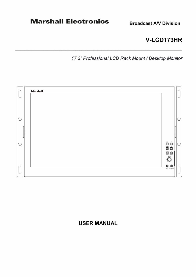
Broadcast A/V Division
V-LCD173HR ___________________________________________________________________________________
17.3” Professional LCD Rack Mount / Desktop Monitor
USER MANUAL
V-LCD173HR Manual
Marshall V-LCD173HR 2
Table of Contents 1. Introduction, Installation, and Setup.......................................................................................……………..…….....3 2. Panel Features........................................................................................................................…………..………....3 3. Navigation Main Menu……………………………….........................................……….……………..........................5
3.1 Main Menu……………….…………………………………………………..……………...…………………………5 3.2 Video Configuration……………….………………………………………………….…………………….…………5 3.3 Marker Configuration………………………………………………………..……….………….………………….…6 3.4 Display Configuration………………………………………………………….……………………….……………..7 3.5 Function Configuration………………………………………………………………………….…….…………..…..8 3.6 Audio Configuration………………………………………………………………………………………….……..…9 3.7 System Configuration…………………………………………………………………………………….………..….9
4. Specifications………………………………………………………………………………………………………….…...10 5. Dimensions…………....................................................................................……………………............................13 6. Monitor Care…………………………………………………………………………………………………………..……13 7. Warranty...............................................................................................................................………………..….....14
IMPORTANT SAFETY INSTRUCTIONS:
The V-LCD173HR 17.3” LCD Monitor has been tested for conformance to safety regulations and requirements and has been certified for international use. However, like all electronic equipment, the V-LCD173HR should be used with care. Please read and follow the safety instructions to protect yourself from possible injury and to minimize the risk of damage to the unit.
• Follow all instructions and warnings marked on this unit.
• Do not attempt to service this unit yourself, except where explained in this manual.
• Provide proper ventilation and air circulation and do not use near water.
• Keep objects that might damage the device and assure that the placement of this unit is on a stable surface.
• Use only the power adapter and power cords and connection cables designed for this unit.
• Do not use liquid or aerosol cleaners to clean this unit. Always unplug the power to the device before cleaning.

V-LCD173HR Manual
Marshall V-LCD173HR 3
1. Introduction, Installation and Setup ______________________________________________
■ Introduction and Installation
The V-LCD173HR 17.3” LCD Monitor can be mounted in any standard EIA 19” equipment rack. The attached rack ears can be angled to provide the user control over the viewing angle. Adequate ventilation is required when installed to prevent possible damage to the monitor’s internal components. Both VESA standard 75mm and 100mm hole pattern allow for custom mounting installations. ■ Package Contents
• 1x V-LCD173HR 17.3” LCD Monitor • 1x DC Adapter • 1x TALLY Connector
NOT INCLUDED: • Optional Marshall “V-ST15” base mount for desktop use • (4) M4 screws needed to install “V-ST15” base mount
■ Connections, Power-On, and Initial Setup
Plug the power supply into an AC power source. Attach the power connector to the back of the monitor. Connect the required cables for video signal input and output. (Power must be supplied to the V-LCD173HR to activate the loop-though output.) The monitor defaults to ‘ON’ when power is supplied. Choose the desired signal source by selecting the “SDI”, “HDMI” or “VIDEO” button on the front bezel.
2. Panel Features _____________________________________________________________
Top and Front Panel Features
1 – Rack Mount Ears: Use rack mount ears to mount 6RU racks or other display applications.
5 – Video Buttons: Indicator lights up when signal switches to VIDEO state.
2 – SDI Button: Indicator lights up when signal switches to SDI state.
6 – Menu Navigation Knob: Turn first for Volume, Brightness, etc or press first for Main Menu.
V-LCD173HR Manual
Marshall V-LCD173HR 4
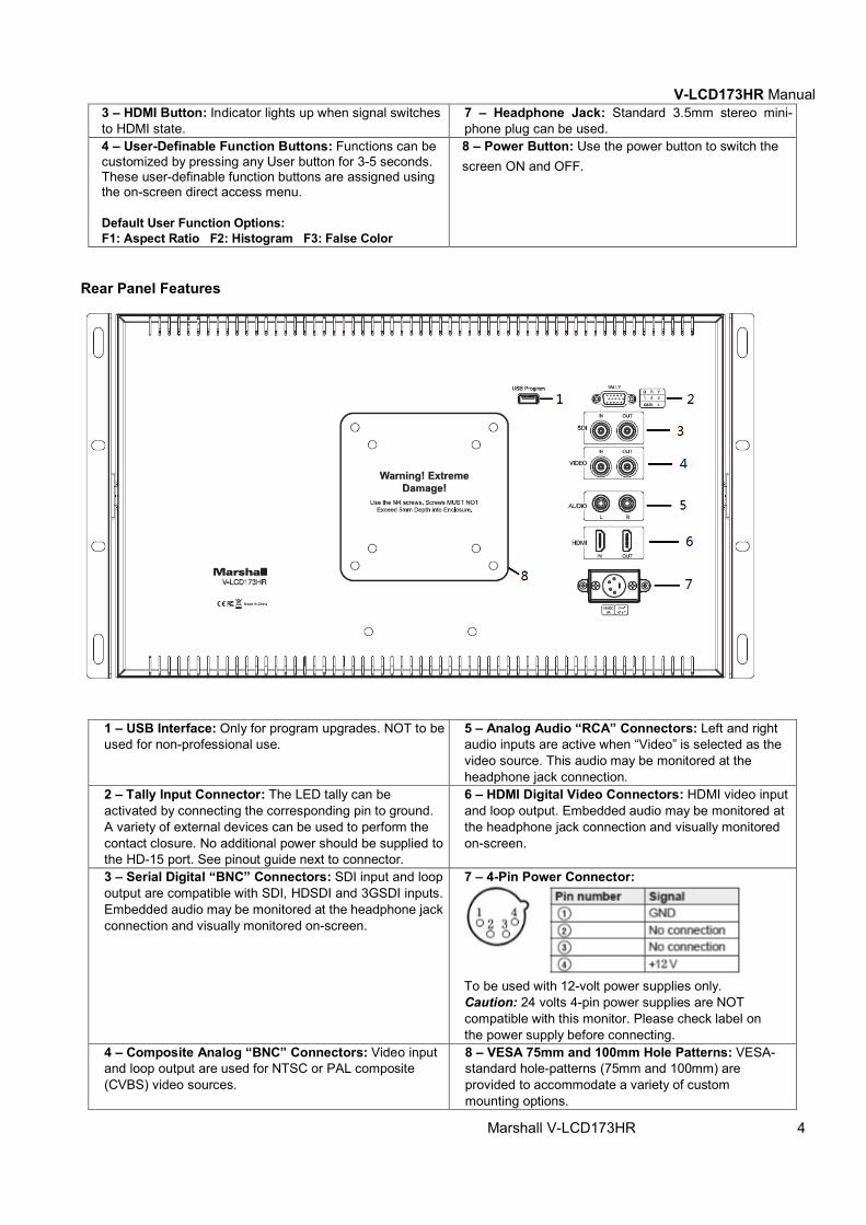
3 – HDMI Button: Indicator lights up when signal switches to HDMI state.
7 – Headphone Jack: Standard 3.5mm stereo mini-phone plug can be used.
4 – User-Definable Function Buttons: Functions can be customized by pressing any User button for 3-5 seconds. These user-definable function buttons are assigned using the on-screen direct access menu. Default User Function Options: F1: Aspect Ratio F2: Histogram F3: False Color
8 – Power Button: Use the power button to switch the screen ON and OFF.
Rear Panel Features
1 – USB Interface: Only for program upgrades. NOT to be used for non-professional use.
5 – Analog Audio “RCA” Connectors: Left and right audio inputs are active when “Video” is selected as the video source. This audio may be monitored at the headphone jack connection.
2 – Tally Input Connector: The LED tally can be activated by connecting the corresponding pin to ground. A variety of external devices can be used to perform the contact closure. No additional power should be supplied to the HD-15 port. See pinout guide next to connector.
6 – HDMI Digital Video Connectors: HDMI video input and loop output. Embedded audio may be monitored at the headphone jack connection and visually monitored on-screen.
3 – Serial Digital “BNC” Connectors: SDI input and loop output are compatible with SDI, HDSDI and 3GSDI inputs. Embedded audio may be monitored at the headphone jack connection and visually monitored on-screen.
7 – 4-Pin Power Connector:
To be used with 12-volt power supplies only. Caution: 24 volts 4-pin power supplies are NOT compatible with this monitor. Please check label on the power supply before connecting.
4 – Composite Analog “BNC” Connectors: Video input and loop output are used for NTSC or PAL composite (CVBS) video sources.
8 – VESA 75mm and 100mm Hole Patterns: VESA-standard hole-patterns (75mm and 100mm) are provided to accommodate a variety of custom mounting options.
V-LCD173HR Manual
Marshall V-LCD173HR 5
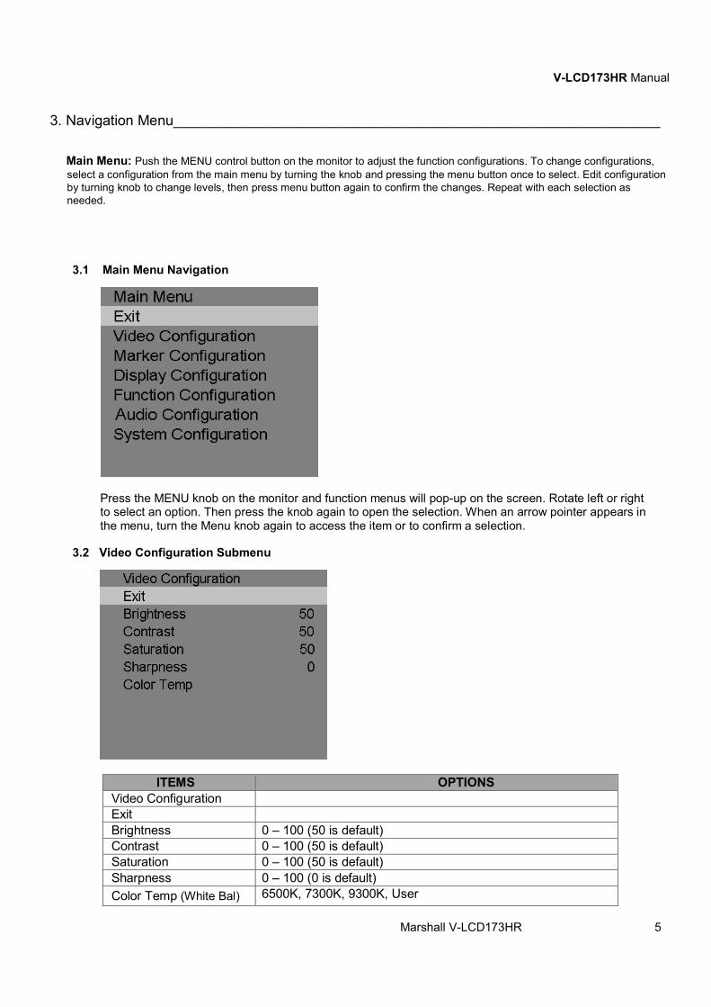
3. Navigation Menu_____________________________________________________________
Main Menu: Push the MENU control button on the monitor to adjust the function configurations. To change configurations, select a configuration from the main menu by turning the knob and pressing the menu button once to select. Edit configuration by turning knob to change levels, then press menu button again to confirm the changes. Repeat with each selection as needed.
3.1 Main Menu Navigation
Press the MENU knob on the monitor and function menus will pop-up on the screen. Rotate left or right to select an option. Then press the knob again to open the selection. When an arrow pointer appears in the menu, turn the Menu knob again to access the item or to confirm a selection.
3.2 Video Configuration Submenu
ITEMS OPTIONS Video Configuration Exit Brightness 0 – 100 (50 is default) Contrast 0 – 100 (50 is default) Saturation 0 – 100 (50 is default) Sharpness 0 – 100 (0 is default) Color Temp (White Bal) 6500K, 7300K, 9300K, User
V-LCD173HR Manual
Marshall V-LCD173HR 6
Color Temp R 0 – 255 Note: These three items appear when “User” mode is selected.
Color Temp G 0 – 255 Color Temp B 0 – 255
■ Brightness The Brightness level ranges from 0 to 100. ■ Contrast The Contrast level ranges from 0 to 100. ■ Saturation The Saturation level ranges from 0 to 100. ■ Sharpness
The Sharpness level ranges from 0 to 100. ■ Color Temp
Choose one of three color temperature presets (6500K, 7300K or 9300K) or define the color with the USER mode.
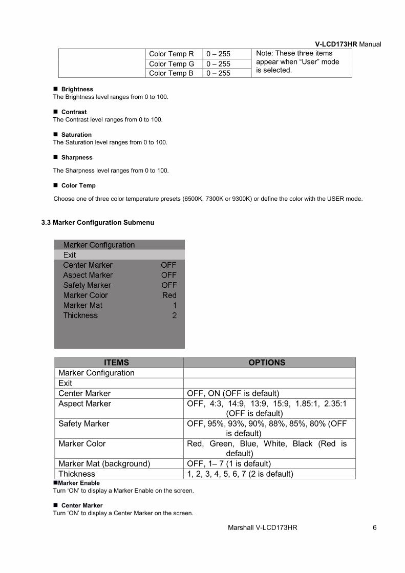
3.3 Marker Configuration Submenu
■Marker Enable Turn ‘ON’ to display a Marker Enable on the screen.
■ Center Marker Turn ‘ON’ to display a Center Marker on the screen.
ITEMS OPTIONS Marker Configuration Exit Center Marker OFF, ON (OFF is default) Aspect Marker OFF, 4:3, 14:9, 13:9, 15:9, 1.85:1, 2.35:1
(OFF is default) Safety Marker OFF, 95%, 93%, 90%, 88%, 85%, 80% (OFF
is default) Marker Color Red, Green, Blue, White, Black (Red is
default) Marker Mat (background) OFF, 1– 7 (1 is default) Thickness 1, 2, 3, 4, 5, 6, 7 (2 is default)
V-LCD173HR Manual
Marshall V-LCD173HR 7
■ Aspect Marker Set the Aspect Marker on the screen. Options: OFF, 4:3, 14:9, 13:9, 15:9, 1.85:1, 2.35:1. ■ Safety Marker Use this to superimpose one of 6 Safety Markers on the screen. Options: OFF, 95%, 93%, 90%, 88%, 85%, 80%. ■ Marker Color Choose from 5 Marker Colors: Red, Green, Blue, White, or Black.
■ Marker Mat (marker background) Choose the Marker Mat transparency. Options: OFF,1-7. ■ Thickness Choose the Marker Line Thickness ranging from 1 to 7.
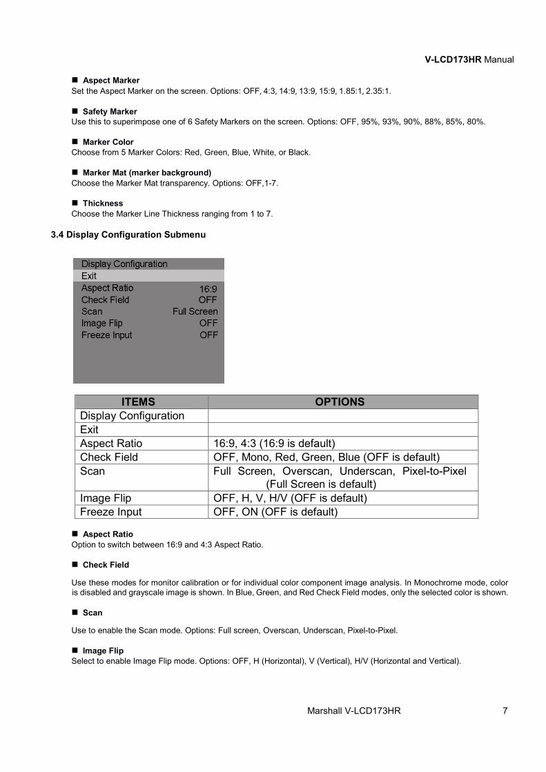
3.4 Display Configuration Submenu
ITEMS OPTIONS Display Configuration Exit Aspect Ratio 16:9, 4:3 (16:9 is default) Check Field OFF, Mono, Red, Green, Blue (OFF is default) Scan Full Screen, Overscan, Underscan, Pixel-to-Pixel
(Full Screen is default) Image Flip OFF, H, V, H/V (OFF is default) Freeze Input OFF, ON (OFF is default)
■ Aspect Ratio Option to switch between 16:9 and 4:3 Aspect Ratio.
■ Check Field
Use these modes for monitor calibration or for individual color component image analysis. In Monochrome mode, color is disabled and grayscale image is shown. In Blue, Green, and Red Check Field modes, only the selected color is shown. ■ Scan
Use to enable the Scan mode. Options: Full screen, Overscan, Underscan, Pixel-to-Pixel.
■ Image Flip Select to enable Image Flip mode. Options: OFF, H (Horizontal), V (Vertical), H/V (Horizontal and Vertical).

V-LCD173HR Manual
Marshall V-LCD173HR 8
■Freeze Input Turn ‘ON’ to enable Freeze Input mode. A still image will remain on the screen until Freeze is turned off or power is removed from the monitor.
3.5 Function Configuration Submenu
ITEMS OPTIONS Function Configuration Exit Peaking OFF, ON (OFF is default) Peaking Color Red, Green, Blue, White, Black (Red is default) Peaking Level 0 – 100 (50 is default) Note: This option is
disabled when Peaking is set to OFF. False Color OFF, ON (OFF is default) Exposure ON, OFF (OFF is default) Exposure Level 0 – 100 (15 is default) Note: This option is
disabled when Exposure is set to OFF. Histogram OFF, Y, RGB, Color (Y is default) DSLR Scale OFF, ON (Available for HDMI input only.)
■ Peaking
Turn ‘ON’ to enable Peaking mode.
■ Peaking Color When Peaking Mode is enabled, the monitor will add color to sharply defined edges and objects in an image. This is intended as a tool to aid in judging sharp camera focus. When a camera is adjusted for best focus, the object of interest will have colored edges. Choose from 5 Peaking Colors: Red, Green, Blue, White, or Black. Normally, this function is turned on only as long as needed for focus adjustment and then turned off for normal monitor operation.
■ Peaking Level The Peaking Level ranges from 0 to 100. ■ False Color Turn ‘ON’ to enable False Color mode. When this is on, the picture will have colors added based on video level. It is useful to make a quick check to see if level exceed normal black and white limits or to make a comparison between one scene or lighting situation and another.

V-LCD173HR Manual
Marshall V-LCD173HR 9
■ Exposure Turn ‘ON’ to enable Exposure Level mode.
■ Exposure Level The Exposure Level setting ranges from 0 to 100. This function mimics the “zebra pattern” display that is often used in many camera viewfinders. It provides a quick check for proper camera exposure. When it is turned ON, diagonal lines will appear in the image areas where the brightness matches the level Exposure Level setting. This is useful when a camera angle has been changed and it is important to keep certain objects at the same brightness. On a typical video scale of 0 – 100, the Exposure number relation is shown in the table below. That is, “zebra patterns” appearing on the image indicates that the area covered by the zebra pattern matches or exceeds the selected video level.
EXPOSURE LEVEL NUMBER
APPROXIMATE VIDEO LEVEL
15 100% 40 90% 70 80% 100 70%
■ Histogram Use to enable the Histogram mode. Options: OFF, Y (shown), RGB (with color), Color (RGB colors individually shown). The Histogram display is similar to displays used in DSLR cameras and desktop color processing applications. It provides a graphic representation of the amount of dark, mid and light tones in an image. It is useful for comparing the average “balance” between different “real” images, not test patterns.
■ DSLR SCALE (HDMI Input Only) Turn ‘ON’ to enable DSLR Scale mode.
3.6 Audio Configuration Submenu
ITEMS OPTIONS
Function Configuration Exit Audio 0 – 100 (50 is default)
■ Audio The Audio level ranges from 0 to 100.
3.7 System Configuration Submenu

V-LCD173HR Manual
Marshall V-LCD173HR 10
ITEMS OPTIONS System Configuration Exit Language English, Chinese (English as default) HDMI/SDI Convert OFF, ON (OFF as default) Menu Timer 10s, 20s, 30s (10s as default) Back Light 0 – 100 (100 as default) Reset OFF, ON ISP Firmware Version
V3.3
■ Language Choose Language: English or Chinese. ■ HDMI/SDI Convert Turn ‘ON’ to enable HDMI/SDI Convert mode. ■ Menu Timer The menu timer level ranges from10s, 20s, 30s.
■ Back Light The Back Light level ranges from 0 to 100. Back Light adjustment is commonly used to compensate for ambient light levels in the viewing environment and is preferred over using Contrast and Brightness for this. ■ Reset Turn ‘ON’ to enable reset mode. ■ ISP ISP is for service use only. ■ Firmware Version Display firmware version (V3.3 at the time this manual was prepared).

V-LCD173HR Manual
Marshall V-LCD173HR 11
4. Specifications_______________________________________________________________
Model Name V-LCD173HR
Role of Usage 17.3” LCD Monitor Connectors
Inputs • SDI BNC x 1 with Loop Out • HDMI x 1 with Loop Out • Composite BNC x 1 with Loop Out • Audio L/R RCA x 2 Line Level • Tally HD-15 Pin compatible with GPI open collector or contact closure to ground/earth • USB 3.0 USB-A x 1 (Firmware Updates) • XLR-12V 4 pin x 1
Outputs • 3.5 mm Front Panel Stereo Headphone Jack
Hardware • Included Rack Ears x 2 (6RU height) for standard 19” rack mount
• Back Panel Supports VESA 100x100mm and 75x75mm mounting systems • Optional Desktop Stand Model V-ST15 Available • Weight 7.9 lbs. (3.6 Kg) • Product Dimension: 1.29” x 17.75” x 10.5” / 3.28cm x 45cm x 26.7cm (D x L x W)
Panel Information
• Native Resolution:1920x1080 pixels • Contrast Ratio: 700:1 • Luminance: 300 nits • Display colors: 16 million colors • Viewing Angle: 178-degrees H & V
Supported Formats / Frame Rates Composite Input • NTSC
• PAL
SD-SDI Input • 480i 59.94Hz • 576i 50Hz
HD-SDI • 720p 25, 29.97, 30, 50, 59.94, 60 Hz • 1080i 50, 59.94, 60 Hz • 1080psf 23.98, 24.00 Hz • 1080p 23.98, 24, 25, 29.97, 30 Hz
3G-SDI Level A
• 1080p 50, 59.94, 60 Hz • 10800i 50, 59, 60 Hz • 1080psf 23, 24, 25, 29.97, 30 Hz • 1080p 23.98, 24, 25, 29.97, 30 Hz
SD - HDMI • 480i 59.94, 60 Hz • 576i 50 Hz • 480p 59.94, 60 Hz • 576p 50Hz
HD - HDMI • 720p 25, 29.97, 30, 50, 59.94, 60 Hz • 1080i 50, 59.94, 60 Hz • 1080psf 23.98, 24 Hz • 1080p 23.98, 24, 25, 29.97, 30 Hz

V-LCD173HR Manual
Marshall V-LC173HR 12
5. Dimensions_________________________________________________________________
6. Monitor Care________________________________________________________________ Screen Cleaning
Periodically clean the screen surface using ammonia-free cleaning wipes (Marshall Part No. V-HWP-K). A clean micro-fiber cloth can also be used with only non-abrasive and ammonia-free cleaning agents. Do not use paper towels. Paper towel fibers are coarse and may scratch the surface of the polycarbonate faceplate or leave streaks on the surface. Antistatic and fingerprint resistant cleaning agents are recommended. Do not apply excessive pressure to the screen to avoid damaging the LCD. Faceplate Dusting
Dust the unit with a soft, damp cloth or chamois. Dry or abrasive cloths may cause electrostatic charge on the surface, attracting dust particles. Neutralize static electricity effects by using the recommended cleaning and polishing practice.

V-LCD173HR Manual
Marshall V-LC173HR 13
7. Warranty ___________________________________________________________________
Marshall Electronics warranties to the first consumer that this V-LCD173HR 17.3” LCD Monitor will, under normal use, be free from defects in workmanship and materials, when received in its original container, for a period of one year from the purchase date. This warranty is extended to the first consumer only, and proof of purchase is necessary to honor the warranty. If there is no proof of purchase provided with a warranty claim, Marshall Electronics reserves the right not to honor the warranty set forth above. Therefore, labor and parts may be charged to the consumer. This warranty does not apply to the product exterior or cosmetics. Misuse, abnormal handling, alterations or modifications in design or construction void this warranty. No sales personnel of the seller or any other person is authorized to make any warranties other than those described above, or to extend the duration of any warranties on behalf of Marshall Electronics, beyond the time period described above. Note: Due to constant effort to improve products and product features, specifications may change without prior notice.
Marshall Electronics, Inc. 20608 Madrona Avenue, Torrance, CA 90503
Tel: (800) 800-6608 / (310) 333-0606 • Fax: 310-333-0688
www.LCDracks.com [email protected]