Embed Size (px)
Citation preview
V-notch weir boxes for measurement of subsurface drainagesystem discharges
P. MILBURN1 and J. BURNEY2
'Research Station, Agriculture Canada, Fredericton, New Brunswick E3B 4Z7; and Agricultural Engineering DepartmentTechnical University ofNova Scotia, Halifax, Nova Scotia B3J 2X4. Received 4August, 1987, accepted 24 December 1987.
Milburn, P. and Burney, J. 1988. V-notch weir boxes for measurement ofsubsurface drainage system discharges. Can. Agric. Eng.30: 209-212. Portable discharge measurement structures that accuratelymeasurethe rangeof outflowscommonto field-scalesubsurfacedrainage systems are not readily available at reasonable cost. Construction drawings andcalibration results are presented for two non-900 sharp-crested V-notch weir boxes designed to discharge a maximum of 10and 20 L/sat 300mmof head. Thecompleted structuresare light-weight, durable, compact in size, simple to construct, andbaffled to reduce turbulence in the approach section to the notch.
INTRODUCTION
Case studies or field experiments that assess the performanceof subsurface drainagesystemsoften require the accuratedetermination of drainage system outflow, on a periodic or continuous basis. Maximum flows of from 10 to 20 L/s may beencountered at a single outlet, depending on drain depth andspacing, soil saturated hydraulicconductivity, the numberandlength of drain laterals in the system, and the capacity of thecollector or main line. Accurate measurement of these flowsrequires a discharge measurement structure that operates overa rangeof headseasily detectablewith common stage recordingdevices such as float-pulley systems, bubblers, or pressuretransducers.
Thesharp-crested (thinplate)V-notch weirhas the advantageof measuring small discharges accurately and covering a widerange of flows; however, it is sensitive to approach conditionssuch as velocity distribution in the upstream channel and construction detail of the notch (Ackers et al. 1978). Dischargevelocities at a drain outlet can approach 0.6 to 2.4 m/s whenthe collector or main line is installed on slopes of 1-10% (SoilConservation Service 1984). This condition is common todrainage systems installed on the rolling terrain of MaritimeCanada. For a V-notch weir to be used with drain outlets dis
chargingat the above velocities, it should include energy dissipatingdevices to minimize turbulence in the approach sectionto the notch.
The objective of this project was to construct and calibratetwo sharp-crested V-notch weirs, one with an outflow of 10 L/s at 300 mm head, and the other with an outflow of 20 L/s at300 mm head. They were to operate under visually non-turbulent flow conditions in the approach section to the notch,have a low head requirement, be light weight, easily transportable (not excessively bulky), sturdy, and simple toconstruct.
CANADIAN AGRICULTURAL ENGINEERING
FLOW
60°min.
Figure 1. V-notch sharp-crested weir: (a) schematic showing majordimensions; (b) cross section of weir plate. After Bos (1978).
THEORETICAL AND PRACTICAL
CONSIDERATIONS
Bos (1978), Ackers et al. (1978), and Grant (1985) reviewedthe literature on discharge measurement structures includingsharp-crestedV-notch weirs; they provided a thorough discussion of the hydraulic principles governing flow through weirsand flumes. Based on the proximity of the weir walls and floorto the notch, Bos (1978) classified sharp-crested V-notch weirs
209
as either partially contracted or fully contracted. In the fullycontracted case the floors and walls are sufficiently remote soas not to affectthe geometry of the nappe. A fully contractedweir is therefore generally wider and deeper than a partiallycontracted weir for agivenhead, h. For the partially contractedcase the following limits to weirdimensions apply (Fig. 1):
h/P^l.2; h/B^OA;0.05 m<h^0.6 m; P^O.l m; B^0.6 m,
where P is the vertexheightabove bed level and B is the widthof the rectangular approach section. Other design recommendations from Ackers et al. (1978) and Bos (1978) include: ahead measurement station located upstream from the notch adistance of three to four times the maximum head on the notch;a tailwater level at least 50 mm below the vertex of the notch,to provide adequate ventilation of the nappe; a V-notch crestwitha sharp, narrow, horizontal top surface free from roundingor burrs, 1-2 mm thick (Fig. 1); a rectangular approachchannel.
Assuming fully contracted conditions and a coefficient ofdischarge of 0.6, the approximate V-notch angles required todischarge 10 and 20 L/s at 300 mm head may be calculatedfrom the general V-notch equation presented by Streeter (1971)as 16.3° and 32.0°, respectively. However, Bos (1978) relatedthat, owing to a lack of experimental data on the value of thedischarge coefficient over a sufficiently wide range of hIP andPIB ratios,discharge-head equations for partially contracted V-notch weirs areavailableonly for 90° notches. This implies that
for cases where a partially contracted non-90° V-notch weir isdesired(due to small flow volumes, space limitations, or someother combination of operational requirements) final calibrationof the structure is required to determine the head-dischargerelation.
Sincethe dimensional requirements fora partially contractedV-notch weir were larger thanthat desired by the authors, andsince apartially contracted non-90° V-notch weir would requirecalibrationeven if it conformed to the criteria presented by Bos(1978) (that is, for h = 0.3 m,^ = 0.75 m,/^ = 0.25 m),it was decided to construct a nonstandard weir box from light,readily available materials, determine therequired notch angleby trial-and-error, and calibrate the resultant structure. Dueconsideration wasgivento maintaining nonturbulent flowintheapproach section tothe notch, providing asmooth, sharp-edgedprofile onthe V-notch, and providing adequate aeration for thenappe. It was acknowledged attheoutset that some design recommendations already presented would be sacrificed in anattempt to produce a small, simple structure with acceptablemeasurement accuracy for field studies.
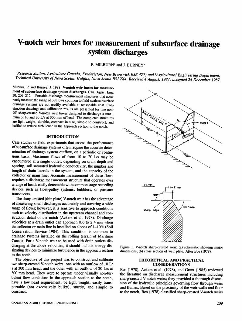
The material selected was standard 4x8 sheets of 3-mm aluminum. Construction details of the weirs are shown in Fig. 2.The notches have a 45° bevel to knife edge. The width of theweir box is 405 mm and 760 mm for the 10-L/s and 20-L/smodels, respectively. The decision to increase the width of thelatter was made following observation of excessive flow turbulence and some surface instability in the weir approach sec-
wire at25 spacing
405 for 10 Us760 for 20L/s
P, f^52 I.D.1 13 pvc
' ' Sh 40
i-TTr^-25x25x3angle
—i 1 r
VIEW XX TO YY
All values in mm
^-6 dia."~ holes
S0METRIC
SECTION 11Figure 2. Weir boxes constructed from standard sheets of 3-mm aluminum.
210 MELBURN AND BURNEY
30
10
1
0.5
CD
cr
<Xo
? 0.1
0.05-
0.01
10
oo
clinging ^-nappe
-I i i I i nil
50 100
f -5 2.470'- q-1.55x10 h
/ x h 3*1000 /
/ x -5 2.39|I /- q- 1.23x10 h
/ x hs*100
o 20 L/s boxx 10 L/s box
clean nappeseparation
_i i i I i i ii I500
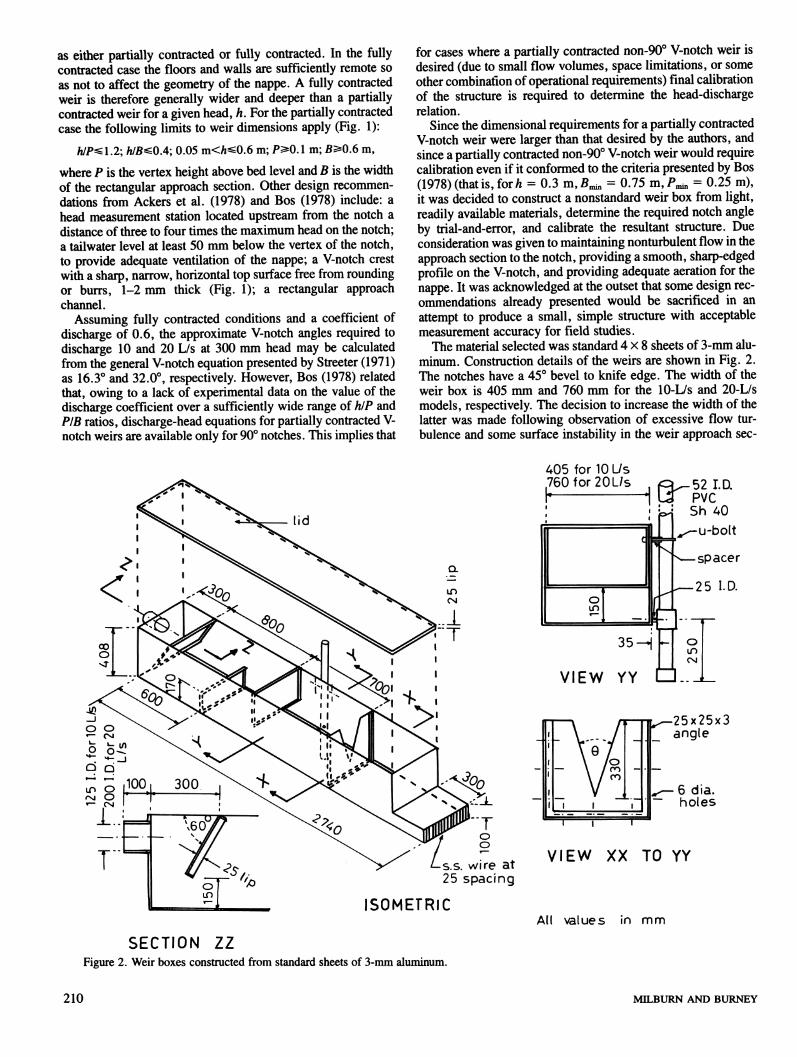
HEAD (h)f mmFigure 3. Weir box calibration curves.
tion of the 405-mm-wide box under 20 L/s operating conditions. With the widened condition (760 mm), calculatedaverage approach velocity at full flow operation is 0.12 m/s,corresponding to a negligible velocity head of 0.7 mm. Thefloor and walls of the 10-L/s unit is formed from a single 4x8sheet (no welds). The 20-L/s unit has a single sheet for the floorand one wall; the remaining side is cut to size and welded.
Solid baffles, each with a 25-mm lip to increase rigidity wereinstalled as shown in Fig. 2. Sections of 25 x 25 x 3 mm aluminumangle were bolted down each side and across the bottomof the weir box at the V-notch location. V-notches were bolted
to this angle and sealed with silicon sealer. The notch apexextends to 78 mm from the bottom of the weir box. This configurationpermits the 50 mm freeboard for aeration of the nappe
as recommendedby Bos (1978), and also allows for a full stageof 300 mm within a weir box constructed from a standard 4x8sheetof 3-mmaluminum. Dischargethroughthe notchis spreadacross the entire weir box, thus providing ample discharge areaand preventing unwanted back water affects. The V-notch discharges within the box itself rather than directly into a ditch orwatercourse, and the weir box is covered with a lid; both measures prevent damage to the notch by unauthorized persons orby animals.
V-notch anglesof 16.2°and33.2° wererequiredto discharge10 and 20 L/s at 300 mm head, respectively.
CALIBRATION AND TESTING
Each of the 10 and 20 L/s weir boxes was calibrated in thelaboratory. A weir box under test was set in position, with theoutlet over a below-floor sump, and the bottom levelled horizontally. Water was supplied to the inlet end of the weirbox bya two-stage system: (1) pumps delivered water from the below-flow sumpto a supplytank;(2)waterthenflowed freelythrougha pipe from the supply tank to the weir. The supply tank wasused to modulate pumping fluctuations. Flow out of the weirbox returneddirectly to the sump. Discharge was regulated bya valveon one of the pump lines, and by using a feweror greaternumber of pumps as required.
Each weir box was calibrated at seven 40-mm increments ofhead on the V-notch between 300 and 60 mm head. A finalreading was taken at 30 mm head.
For each calibration point, flow was adjusted and allowed tocome to equilibrium at the required head, as measured by ametre rule (1-mm graduations) clamped to the side of the weirbox at the location of the stilling well inlet. Discharge readingswere then taken using a stopwatch and a 300-L containermounted on a calibrated spring scale. The calibration data arepresented in Table I and illustrated in Fig. 3.
In particular, it was noted that for both weir boxes the nappetended to separate cleanly until the head on the V-notch droppedto about 100 mm. For lower heads nappe separation wasincreasingly less clean until in the region of 30 mm head allflow through the V-notch ran down the outside of the V-notchplate. Calibration equations were, therefore, fitted to the head\h) and discharge (q) data sets in two segments:
1. For h^ 100 mm, an equation of the form
q = Ahb (1)was fitted statistically (r2= 0.999).
2. For h^lOO mm, a quadratic equation of the form0= £{C+Dlnh +E(lnh)2} Q\
Table I. Calibration data
10 L/s box 20 L/s box
Avg. Number Avg. Number
Head, h discharge CV of discharge CV of
(mm) (L/s) (%) readings (L/s) (%) readings
300 9.97 0.07 3 19.91 1.17 5
260 7.02 0.18 3 13.92 1.03 5
220 4.75 0.35 3 9.13 0.72 5
180 2.96 0.14 3 5.59 0.40 5
140 1.60 0.76 3 3.09 0.39 5
100 0.73t 1.33 3 1.31t 0.63 3
60 0.22 0.93 3 0.38 2.17 3
30 0.047 2.04 3 0.074 1.30 3
tLower limit of nappe separation.
CANADIAN AGRICULTURAL ENGINEERING 211
was fitted mathematically to the calibrated points at h = 30mm and 60 mm, and to the value of q at h = 100 mm asdetermined by Eq. 1 (three equations, three unknowns). Thisprocedure ensured a unique q value for Eqs. 1 and 2 at h =100 mm.
CONCLUSION
Two non-90° V-notch weir boxes, small in size and weight andsimple to construct, that discharge 10 and 20 L/s at 300 mmhead were fabricated and calibrated. Notch angles are 16.2°and33.2°, respectively. The structuresare shallower, narrower, andshorter than partially contracted V-notch weirs. The head-dischargerelationship is a powerfunction for h values 100 ^ h ^300 mm, and deviates only slightly from the power functionfor the range 100 < h ^ 30 mm. Clinging of the nappe to thedownstream face of the weir plate was increasingly observedfor h values less than 100 mm; at approximately 30 mm all flowran down the outside of the V-notch plate. It is recommendedthat the weirs not be used for h values less than 30 mm.
212
ACKNOWLEDGMENTS
The authors wish to acknowledge the assitance of Mr. Jack Vis-sers and Mr. Jim Godwin in construction and testing of theweirs.
REFERENCES
ACKERS, P., W. R. WHITE, J. A. PERKINS, and A. M. HARRISON. 1978. Weirs and flumes for flow measurement. John Wiley andSons, New York. 321 pp.BOS, M.G. (ed.). 1978. Discharge measurement structures. International Institute for Land Reclamation and Improvement, P.O. Box 45,6700 AA, Wageningen, The Netherlands. 420 pp.GRANT, D. M. 1985. Open channel flow measurement handbook.Isco, Inc., P.O. Box 82531, Lincoln, Nebraska 68501. 227 pp.SOIL CONSERVATION SERVICE. 1984. Engineering field manualfor conservation practices, chapter 8, H. Kautz, chairman. FourthPrinting. USDA, Washington, D.C.STREETER, V. L. 1971. Fluid mechanics. McGraw-Hill Book Company, New York. 755 pp.
MILBURN AND BURNEY