Embed Size (px)
Citation preview

3 R 74 EN Issue 9/2020
V-port segment valvesSeries RInstallation, Maintenance andOperating Instructions

2 3 R 74 EN - Issue 9/2020
READ THESE INSTRUCTIONS FIRST!
These instructions provide information about safe handling and operation of the valve.
If you require additional assistance, please contact the manufacturer or manufacturer's representative.
SAVE THESE INSTRUCTIONS!
Addresses and phone numbers are printed on the back cover.
Subject to change without notice.All trademarks are property of their respective owners.
TABLE OF CONTENTS
GENERAL 3Scope of the manual 3Valve construction 3Valve markings 3Technical specifications 4Valve approvals 6CE marking 6Recycling and disposal 6Safety precautions 6
TRANSPORTATION, RECEPTION AND STORAGE 6INSTALLATION 6General 6Installing in the pipeline 6Actuator 7
COMMISSIONING 7MAINTENANCE 7Maintenance general 7Replacing the gland packing 8Detaching the actuator 9Removing the valve from the pipeline 9Replacing the seat 9Dismantling the valve 11Inspection of removed parts 11Assembly 12
TESTING THE VALVE 12INSTALLING AND DETACHING THE ACTUATORS 13General 13Installing B1C actuators 13Installing B1J actuators 13Detaching B series actuators 13Installing a Quadra-Powr® actuator 14
TROUBLE SHOOTING TABLE 15TOOLS 15ORDERING SPARE PARTS 15EXPLODED VIEWS AND PARTS LISTS 16Series RA 16Series RE 17
DIMENSIONS AND WEIGHTS 18Series RA 18RA-B1C 19RA - B1J, B1JA 20RA - M 21Series RE 22RE - B1C 23RE - B1J, B1JA 24RE - QPX 25Suitability with different flanges,RA and RE1 valves 26Flange ratings, RE(Class 150, 300) 26
TYPE CODE 27Series RA 27Series RE, RE1 28

1 GENERAL1.1 Scope of the manualThis manual provides essential information on R series V-port segment valves, i.e. RA, RE and RE1-series valves. Actuators and other accessories are only discussed briefly. Refer to the individual manuals for further information on their installation, operation and maintenance.
1.2 Valve constructionRA, RE and RE1-series valves are V-port segment valves installed between flanges. RE series valves are flanged V-port segment valves. The body is in one part; the shaft and the segment are separate. Shaft blow-out is prevented by plates mounted against the shaft shoulder. See Figs. 1 and 2.The valve is either soft or metal seated. Tightness derives from the spring force pressing the seat against the segment. The structure of the valve supplied may vary, depending on the customer’s requirements. The detailed structure is revealed by the type code shown on the valve identification plate. The type code is explained in Section 15.The valve is designed for both control and shut-off applications.
1.3 Valve markingsBody markings are cast on the body. The valve also has an identification plate attached to it, see Fig. 3.
Identification plate markings:1. Body material2. Shaft material3. Segment material4. Seat material5. Maximum operating temperature6. Minimum operating temperature7. Maximum shut-off pressure differential8. Type designation9. Valve manufacturing parts list no.10. Pressure class11. Model
NOTE:Selection and use of the valve in a specific applica-tion requires close consideration of detailed aspects.Due to the nature of the product, this manual cannotcover all the individual situations that may occurwhen the valve is used.If you are uncertain about use of the valve or its suit-ability for your intended purpose, please contactNeles for more information. For valves in oxygen service, please see also theseparate installation, maintenance and operatinginstructions for oxygen service (see Neles documentid: 10O270EN.pdf).
Fig. 1 Construction of a V-port segment valve, RA
Fig. 2 Construction of a V-port segment valve, RE/RE1
Fig. 3 Identification plate
Sizes 25–80
Sizes ≥ 100
(1) (3) (5) (6) (7)
(4) (9) (8)
(1) (3) (5) (6) (8) (9)
(2) (4) (7) (10) (11)
(11)
3 R 74 EN - Issue 9/2020 3

1.4 Technical specifications
Face-to-face length: RA: According to Neles internal standardRE, RE1: acc. to IEC/EN 534-3-2
Body rating: RA: ASME Class 300 or PN 40RE, RE1: ASME Class 300 or PN 50/PN40NPS 1" has option of ASME Class 600 or PN 63/PN 100
Max. pressure differential: see Figs. 6 ... 12Temperature ranges: RA-series:
-40 °C... +260 °C. RE-series:
-50 °C ... +260 °C with soft bearings-50 °C ... +315 °C with metal bearings in sizes 2" - 10"-50 °C ... +425 °C with metal bearing and high temperature seats in sizes 2" - 10".
Flow direction: indicated by an arrow on the bodyDimensions: see Section 11Weights: see Section 11Note that max. shut-off and max. throttling pressures are based on mechanical maximum differential pressures at ambient temperature. You must always observe flowing temperature and flange rating when concluding applicable pressure values. In practice you must also check noise level, cavitation intensity, velocity, actuator load factor, etc. using Nelprof.
Initial openings (%) for RE/RA segment valves with different seats.
Seat
Size S & A 1S T2
25 14,2 12,8 24,1
C005 25/1 10.3 N/A 16.1
C015 25/2 10.3 N/A 16.1
C05 25/3 10.3 N/A 16.1
C15 25/4 10.3 N/A 16.1
40 11.9 9.3 18.6
50 16.7 11.4 21.1
65 12.6 10.6 16.8
80 8.9 7.8 14.1
100 8.1 7.0 14.1
150 7.0 5.6 12.2
200 6.2 5.9 11.4
250 6.1 5.6 9.7
300 5.6 5.0 9.0
350 5.2 5.4 8.6
400 5.1 4.4 8.2
500 4.4 4.4 7.1
600 N/A 5.9 N/A
700 N/A 6.3 N/A
4 3 R 74 EN - Issue 9/2020

3 R 74 EN - Issue 9/2020 5
Fig. 4 Body pressure ratings, WCB
Fig. 5 Body pressure ratings, CF8M
Fig. 6 Max operating pressure differential in control service, RE opening range 0 %-70 %
Fig. 7 Max operating pressure differential in control service, RE opening range 70 %-100 %
0
10
20
30
40
50
60
0 50 100 150 200 250 300 350 400 450
Pres
sure
bar
Temperature °C
ASME 150
ASME 300
PN10
PN16
PN25
PN40
102ASME 600, 1”
70
80
90
0
10
20
30
40
50
60
0 50 100 150 200 250 300 350 400 450
Pres
sure
bar
Temperature °C
ASME 150
ASME 300
PN10
PN16
PN25
PN40
ASME 600, 1”
70
80
90
100
0
10
20
30
40
50
60
0 50 100 150 200 250 300 350 400 450
Pres
sure
Bar
Temperature °C
DN25-80/1"-3"
DN100-150/4"-6"
DN200-250/8"-10"DN300-700/12"-28"
0
5
10
15
20
25
30
35
40
Pres
sure
Bar
DN25-80/1"-3"
DN100-200/4"-8"
DN250/10"
DN300-700/12"-28"
0 50 100 150 200 250 300 350 400 450Temperature °C
Fig. 8 Max operating pressure differential in control service, Q-RE opening range 0 %-30 %
Fig. 9 Max operating pressure differential in control service, Q-RE opening range 30 %-60 %
Fig. 10 Max operating pressure differential in control service, Q-RE opening range 60 %-100 %
Fig. 11 Maximum pressure differentials in on-off operation, AISI 329 Shaft
Fig. 12 Maximum pressure differentials in on-off operation, 17-4PH Shaft
0
10
20
30
40
50
60
Pres
sure
Bar
DN50-80/2"-3"
DN100-150/4"-6"
DN200-250/8"-10"DN300-600/12"-24"
DN700/28"
0 50 100 150 200 250 300 350 400 450Temperature °C
0
10
20
30
40
50
60
Pres
sure
Bar
DN50&80/2"&3"DN65/2,5"
DN100/4"
DN150/6"DN200/8"
DN250/10"DN300-600/12"-24"
DN700/28"
0 50 100 150 200 250 300 350 400 450Temperature °C
0
5
10
15
20
25
30
35
40
Pres
sure
Bar
DN50-80/2"-3"
DN100-4"
DN150/6"
DN200/8"
DN250/10"DN300-600/12"-24"DN700/28"
0 50 100 150 200 250 300 350 400 450Temperature °C
0
10
20
30
40
50
60
0 50 100 150 200 250 300 350
Pres
sure
Bar
Temperature °C
DN25-80/1"-3"
DN100-150/4"-6"
DN200-250/8"-10"
DN300-700/12"-28"
0
10
20
30
40
50
60
0 50 100 150 200 250 300 350 400 450
Pres
sure
Bar
Temperature °C
DN25-80/1"-3"
DN100-150/4"- 6"DN200-250/8"-10"
DN300-700/12"-28"

1.5 Valve approvalsValve meets the Fire safe requirements of ISO 10497:2010 - API 607, seventh edition.
1.6 CE markingThe valve meets the requirements of the European Directive 2014/68/EU relating to pressure equipment, and has been marked according to the Directive.
1.7 Recycling and disposalMost valve parts can be recycled if sorted according to material. Most parts have material marking. A material list is supplied with the valve. In addition, separate recycling and disposal instructions are available from the manufacturer. A valve can also be returned to the manufacturer for recycling and disposal against a fee.
1.8 Safety precautions
2 TRANSPORTATION, RECEPTION AND STORAGE
Check the valve and the accompanying devices for any damage that may have occurred during transport.Store the valve carefully before installation, preferably indoors in a dry place.
Do not take the valve to the intended location and do not remove the flow port protectors until the valve is installed.The valve is delivered in the closed position. A valve equipped with a spring-return actuator is delivered in the position determined by the spring.
3 INSTALLATION3.1 GeneralRemove the flow port protectors and check that the valve is clean inside.
3.2 Installing in the pipelineFlush or blow the pipeline carefully before installing the valve. Foreign particles, such as sand or pieces of welding electrode, will damage the segment sealing surface and seats.The valve has an arrow indicating the flow direction. Install the valve in the pipeline so that the flow direction of the pipe corresponds to that marked on the valve. The mounting position does not place restrictions on operation of the valve, actuator or positioner. You should, however, avoid installing the valve so that the shaft points downwards because impurities travelling in the pipeline may then enter the body cavity and damage the gland packing. See Fig. 14.
CAUTION:Do not exceed the valve performance limitations!Exceeding the limitations marked on the valve may cause damage and lead to uncontrolled pressure release. Damage or personal injury may result.
CAUTION:Do not dismantle the valve or remove it from thepipeline while the valve is pressurized!Dismantling or removing a pressurized valve will result in uncontrolled pressure release. Always isolate the relevant part of the pipeline, release the pressure from the valve and remove the medium before dismantling the valve.Be aware of the type of medium involved. Protect yourself and the environment from any harmful or poisonous substances. Make sure that no medium can enter the pipeline during valve maintenance.Failure to do this may result in damage or personal injury.
CAUTION:Beware of the segment movement!Keep hands, other parts of the body, tools and other objects out of the open flow port. Leave no foreign objects inside the pipeline. When the valve is actuated, the segment functions as a cutting device. The segment position may also change when the valve is moved. Close and detach the actuator pressure supply pipeline for valve maintenance. Failure to do this may result in damage or personal injury.
CAUTION:Protect yourself from noise!The valve may produce noise in the pipeline. The noise level depends on the application. It can be measured or calculated using the Neles Nelprof software. Observe the relevant work environment regulations on noise emission.
CAUTION:Beware of a very cold or hot valve!The valve body may be very cold or very hot during use. Protect yourself against cold injuries or burns.
CAUTION:When handling the valve or the valve package, take its weight into account!Never lift the valve or valve package by the actuator, positioner, limit switch or their piping.Place the lifting ropes securely around the valve body (see Fig. 13). Damage or personal injury may result from falling parts.
Fig. 13 Lifting the valve
CAUTION:When handling the valve or the valve package, take its weight into account!
6 3 R 74 EN - Issue 9/2020

The RA and RE1 valves should be applicable to the pipe flanges, see the table in 11.19.Choose flange gaskets according to the operating conditions.
Do not attempt to correct pipeline misalignment by means of flange bolting.Stress caused in the valve by pipeline vibration can be reduced by supporting the pipeline properly. Reduced vibration also helps ensure correct functioning of the positioner.Servicing is facilitated if the valve needs no support. If necessary, you can support the valve by the body, using regular pipe clamps and supports. Do not fasten supports to the flange bolting or the actuator, see Fig. 15.
3.3 Actuator
The valve closed and open positions are indicated by a groove at the end of the valve shaft. The groove shows the position of the segment with respect to the flow port, see Fig. 16. If possible, install the valve so that the actuator can be disconnected without removing the valve from the piping.The actuator must not touch the pipeline, because pipeline vibration may damage it or interfere with its operation.In some cases, for instance when a large-size actuator is used or
when the pipeline vibrates heavily, supporting the actuator is recommended. Contact Neles for further information.
4 COMMISSIONINGEnsure that no dirt or foreign objects are left inside the valve or pipeline. Flush the pipeline carefully. Keep the valve entirely open during flushing.Check all joints, pipings and cables.Check that the actuator, positioner and limit switches are correctly adjusted. Refer to their installation, operation and service manuals.
5 MAINTENANCE5.1 Maintenance general
Although Neles’ valves are designed to work under severe conditions, proper preventative maintenance can significantly help to prevent unplanned downtime and in real terms reduce the total cost of ownership. Neles recommends inspecting the valves at least every five (5) years.The inspection and maintenance interval depends on the actual application and process condition. The inspection and maintenance intervals can be specified together with your local Neles experts. During this periodic inspection the parts detailed in the Spare Part Set should be replaced. Time in storage should be included in the inspection interval.Maintenance can be performed as presented below. For maintenance assistance, please contact your local Neles office. The part numbers in the text refer to the exploded view and to the parts list in Section 10, unless otherwise stated
Fig. 14 Installing the valve into pipeline
Fig. 15 Supporting the valve
NOTE:When installing the actuator, make sure that the valve-actuator combination functions properly. Detailed information on actuator installation is given in Section 6 or in separate actuator instructions.
Fig. 16 Closed and open positions
CAUTION:
Observe the safety precautions mentioned in Section 1.8 before maintenance!
CAUTION:
When handling the valve or the valve package as a whole, bear in mind the weight of the valve or the entire package.
CLOSED OPEN
3 R 74 EN - Issue 9/2020 7

.
5.2 Replacing the gland packing
RA seriesIn gland packing, V-ring set (20), tightness is ensured by pressure caused by the wave spring (32). See Fig. 17.The gland packing must be replaced when leakage occurs through the gland (9).
• Make sure the valve is not pressurized.• Remove the actuator from the valve shaft acc. to the instructions
given in the actuator’s manual.• Remove the key (13) from the drive shaft (11). Unfasten the
screws (25) and the gland (9).• Remove the retainer (30) from the drive shaft. Avoid to damage
the shaft’s surface.• Remove the upper sheet ring (31).• Remove the old packing rings (20) using a pointed pin. Avoid to
damage the sealing surfaces.• Remove the lower sheet ring (31) and the wave spring (32).
• Clean the packing ring counterbore.• Mount the spring (32) and the lower sheet ring (31) into the coun-
terbore.• Mount the new packing rings (20) one by one on the shaft (11)
using the gland (9) as a tool. The keyway and shoulder must not damage the packing rings.
• Mount the upper sheet spring (31).• Mount the retainer (30) in the groove of the shaft. Avoid to dam-
age the surface of the shaft.• Fasten the gland (9) with the screws (25) and tighten them
according to the Table 2.• Mount the key (13) on the shaft (11).
Table 1 Torques for gland screws
RE / RE1 seriesIn gland packings, tightness is ensured by the contact between the gland follower and the packing rings. See Fig. 18.The gland packing (20) must be replaced if leakage occurs even after the hexagon nuts (25) have been tightened.
• Make sure that the valve is not pressurized.• Detach the actuator and bracket according to the instructions in
Section 4.3.• Remove the key (13).• Remove the hexagon nuts (25), disc spring sets (32), one stud
(24), retaining plates (30) and gland follower (9).• Remove the packing rings (20) from around the shaft using a
knife or some other pointed instrument without scratching the surfaces.
• Clean the packing ring counterbore.• Place the new packing rings (20) over the shaft (11). The gland
follower may be used for pushing the rings into the counterbore. Do not damage packing rings in the shaft keyway. See Fig. 18.
• Screw down the removed stud.• Deform the packing rings first by tightening the gland nuts (25)
without disc springs to the torque Tt, see the value from Table 3.
NOTE:When sending goods to the manufacturer for repair, do not disassemble them. Clean the valve carefully and flush the valve internals. For safety reasons, inform the manufacturer of the type of medium used in the valve (include material safety datasheets (MSDS)).
NOTE:In order to ensure safe and effective operation, always use original spare parts to make sure that the valve functions as intended.
NOTE: For safety reasons, replace pressure retaining bolting if the threads are damaged, have been heated, stretched or corroded.
CAUTION:Do not dismantle the valve or remove it from the pipeline while the valve is pressurized!
Fig. 17 Gland packing
30
9
25
32
13
11
31
20
31
Thread Torque, Nm Width across flats
M6M8UNC 1/4UNC 5/16
818818
4 mm5 mm5/32"3/16"
Fig. 18 Gland packing, RE/RE1
A
Hc
24
3032
9
20
25
13
8 3 R 74 EN - Issue 9/2020

• Remove the gland nuts and one stud. Mount the retaining plates (30) with the text UPSIDE on top and the removed stud and place the disc spring sets (32) on the gland studs. Tighten the nuts (25) so that the disc springs are compressed to the height Hc, see Table 3. Lock the nuts with locking compound e.g. Loctite 221. See Fig. 18.
• Check leakage when the valve is pressurized.
Table 2 Tightening of the gland packing
5.3 Detaching the actuator
It is generally most convenient to detach the actuator and its auxiliary devices before removing the valve from the pipeline. If the valve package is small or if it is difficult to access, it may be more practical to remove the entire package at the same time.See Section 6 for details of detaching actuators.
5.4 Removing the valve from the pipeline
• Make sure that the pipeline is not pressurized and that it is empty. Also make sure that no medium is led into the pipeline while the valve is being removed or after it has been removed.
• Place the hoisting ropes carefully, unscrew the pipe flange bolts and lift the valve from the pipeline using the ropes. Note the cor-rect lifting method. See also Fig. 13.
5.5 Replacing the seatS- or U-seat (not DN25-50) can be changed as described in 4.5.1 & 4.5.2. For DN25-50 and other seats, the valve needs to be dismantled as described in 4.6
Detaching the S- or U-seat• The valve must be removed from the pipeline.• Turn the segment (3) so that it does not touch the seat, Fig. 20.
• In DN 65-100 valves (excluding the low-Cv versions), unfasten the blind flange (10) and push the segment into the back position, Fig. 21.
• DN 65-100 valves can be dismantled, as described in 4.6, to make the replacement of the seat easier.
• Tap the seat (4) with a soft spindle all around the circumference from the upstream side to make it fall into the body, Fig. 22.
• Turn the valve and lift the seat from the body through the down-stream flow port, Fig. 23.
• Clean and check the removed parts.
CAUTION:For safety reasons the retainer plates MUST always be installed according to the above instructions.
Fig. 19 Installing the retainer plates
Valve size A (mm) Hc (mm) Tt (Nm)
DN 25 / 01 20 20.5 5
DN 40 / 1H 20 20.5 5
DN 50 / 02 20 20.5 5
DN 65 / 2H 20 20.5 5
DN 80 / 03 20 20.0 7
DN 100 / 04 20 20.0 7
DN 150 / 06 25 29.0 12
DN 200 / 08 25 29.0 14
DN 250 / 10 25 28.0 16
DN 300 / 12 25 28.0 18
DN 350 / 14 35.5 38.0 38
DN 400 / 16 35.5 37.0 45
DN 500 / 20 40 42.0 70
DN 600 / 24 40 41.5 90
DN 700 / 28 40 41.5 90
CAUTION:When handling the valve or the valve package, take its weight into account!
NOTE:Before dismantling, carefully observe the position of the valve in relation to the actuator and positioner/limit switch so as to make sure that the package can be properly re-assembled.
CAUTION:Do not dismantle the valve or remove it from the pipeline while the valve is pressurized!
Fig. 20 Turning the ball segment
Fig. 21 Removing the blind flange
3 R 74 EN - Issue 9/2020 9

Installing the seatThe back seal (6) of the segment seat (4) is normally a lip seal. The seat is easier to install if the back seal is precompressed. An O-ring seal does not need precompression.• Clean the flow port that houses the seat. Remove any burrs.
Round off the edges using a fine abrasive paper and clean the flow port carefully, see Fig. 24. Place the back seal (6) onto the seat (4).
• Lubricate the flow port, seat (4) and back seal (6) and the lock spring (5) with a volatile lubricant, e.g. Hyprez.Make sure that the lubricants are compatible with the medium.
• Only for a lip seal: Push the seal carefully into the flow port for about 15 minutes, Fig. 25. The following work phases must be completed before the precompression is lost.
• Place the lock spring (5) on the seat.• When the valve is opened, the ends of the spring must be by the
V-shaped opening, see Fig. 26.
• Place the seat package into the body as shown in Figs. 27 and 28.
• Check that the spring angles extend to the control face. • Place a screwdriver on each visible spring angle one after the
other and knock the spring into the groove, see Fig. 29. • Turn the segment 180° clockwise and knock the rest of the spring
angles into the groove, Fig. 30. A special tool available from the manufacturer may also be used for the work phases in Figs. 29 and 30.
• Use a plastic spindle to ensure that the seat is correctly placed and can move freely, Fig. 31.
Fig. 22 Knocking off the seat
Fig. 23 Lifting the seat
Fig. 24 Rounding the sharp edges
sharp edgesmust berounded off
sharp edgesmust berounded off
Fig. 25 Precompression of the lip seal
Fig. 26 Mounting the seat
Fig. 27 Slipping the seat into the body
10 3 R 74 EN - Issue 9/2020

5.6 Dismantling the valve• Turn the valve into the closed position.• Remove the pin lockings either by grinding or using a spindle.
Detach the pins (14 and 15) by drilling, Fig. 32. Be careful not to damage the original bores. Note! The pins and the drive shaft have been secured by welding in the titanium version and in the acid-resistant high-consistency version S.
• Detach the retainer plates (30).• Detach the gland packings (20).• Remove the shafts (11 and 12), Fig. 33.• Lift the segment from the body.• Remove the bearings (16 and 17) and clean the bearing spaces.• Remove the seat by pushing it evenly inside the body.
5.7 Inspection of removed parts• Clean the removed parts.• See if the shafts (11, 12) and bearings (16, 17) are damaged.• Check if the sealing surfaces of the segment and the seat (4) are
damaged.• If necessary, replace the parts with new.
Fig. 28 Pushing the the spring angles against the control face
Fig. 29 Knocking the spring into the groove
Fig. 30 Knocking the spring after turning the seat around
Fig. 31 Securing with a plastic spindle
Fig. 32 Drilling the pin
Fig. 33 Installing the shafts
Conical pinpart no. 15DN 25...500
A - A
AA
Cylindrical pinpart no. 14DN 25...40
Cylindrical pinpart no. 14DN 50...500
DN DRILL ø (mm) L (mm)25, 40 2,0 1850, 65 3,5 2580, 100 4,2 33150 5,0 43200 7,0 52250, 300 8,8 60350, 400 12,0 90500 16,0 120
L
3 R 74 EN - Issue 9/2020 11

5.8 Assembly• The bearing material of the standard construction valves is
PTFE-impregnated stainless steel net. The bearings for the high temperature valves are cobalt alloy bushings which are mounted into the body together with the shafts. High temperature is over +260 °C.
• Put the bearings (16, 17) in their places.• Mount the S, U or T-seat as explained in 4.5.2.• For A-seat (Fig. 34), mount the retaining ring (7) to the groove in
Body (1). Install back seal (6), support ring (8) and spring (5) to the seat (7). Mount the assembled seat package to the body. Use a plastic spindle to ensure that the seat is correctly placed.
• Mount the segment in the body in the closed position. In the low Cv version, insert the filling ring (22) between the drive shaft (11) and segment (3). Press the segment to fit the shaft (12).
• For A-seat special compression tool is needed for compress the spring to mount the shaft and drive shaft. See Fig. 33.
• Install the drive shaft (11). Note the location of the pin hole and the keyway. See Figs. 36 and 37.
• High temperature-construction: Mount the bearings (16, 17 and 18) into the shafts. Spray a thin layer of dry lubricating fluid, e.g. Molykote 321R or equivalent, into the inside surface of the bush-ing and the shaft bearing groove. Press the bushing with a tight-ening ring into the shaft bearing groove and fit the shaft with the bearings carefully into the body through the tightening ring.
• Please note the depth of the hole (L) for the conical pin, Fig. 32. Use a former to check the proper shaft position of low Cv valves, see Fig. 36 . Put the pins (14, 15) in their places and lock them, Fig. 37. Both pins are locked with TIG welding in the high-consist-ency acid-resistant version and in the standard and high-consist-ency titanium versions. Moreover, the drive shaft is welded to the segment in the high-consistency versions. Contact the manufac-turer for more information.
• Install the blind flange (10) with gaskets (19), tighten the bolts (26), see Table 3.
• Install the gland packing according to Section 4.2.
Table 3 Screw torques (for lubricated screws)
6 TESTING THE VALVE
We recommend that the valve body be pressure tested after the valve has been assembled.The pressure test should be carried out in accordance with an applicable standard using the pressure rating required by the pressure class or flange bore of the valve. The valve must be in the open position during the test.If you also want to test the tightness of the closure member, contact the manufacturer.
Fig. 34 A-seat
Fig. 35 Segment and shaft positions
Spherical surface
marker line
Fig. 36 Using a former to check shaft position
Fig. 37 Locking a pin
Screw M6UNC 1/4
M8UNC 5/16
M10UNC 3/8
M12UNC 1/2 M16 M29
Torque, Nm 8 18 35 65 170 330
CAUTION:Pressure testing should be carried out using equipment conforming to the correct pressure class!
12 3 R 74 EN - Issue 9/2020

7 INSTALLING AND DETACHING THE ACTUATORS
7.1 GeneralDifferent Neles actuators can be mounted using suitable brackets and couplings. The valve can be operated, for example, by actuators of the E, B1 or Quadra-Powr series.
7.2 Installing B1C actuators
• Drive the actuator piston to the extreme outward position and turn the valve into the closed position, see Fig. 43.
• Clean the shaft bore and file off any burrs. Lubricate the shaft bore.
• If a coupling is needed between the actuator shaft bore and the valve shaft, lubricate the coupling and install it in the actuator.
• Fasten the bracket loosely to the valve using lubricated screws.• Push the actuator carefully onto the valve shaft. Avoid forcing it,
since this may damage the segment and seat. We recommend mounting the actuator so that the cylinder is pointing upwards.
• Align the actuator as accurately as possible using the valve as a guide. Lubricate the mounting screws. Install the washers and tighten all screws, see Table 4.
• Adjust the segment open and closed positions (limits to piston movement) by means of the actuator stop screws, see Fig. 43. The correct opening angle is 90°, for the R2_S valve 70°. The accurate position can be seen in the flow port. Check that the yel-low arrow indicates the position of the segment.Keep your fingers out of the flow port!
There is no need to adjust the stop screw if the actuator is re-installed in the same valve. Drive the actuator piston to the housing end (open position).Turn the actuator by hand until the valve is in the open position (unless it is already open). Fasten the actuator in this position. The actuator may be installed in another position with respect to the valve by selecting another keyway in the actuator, see Fig. 44. • Check the tightness of the stop screw at the end of the cylinder
during cylinder operation. The threads must be sealed using an appropriate non-hardening sealant, e.g. Loctite 225.
• Check that the actuator is functioning correctly. Check the seg-ment flow bore position and the actuator movement relative to the valve (clockwise: close, counterclockwise: open) after install-ing the actuator. The valve should be closed when the piston is in the extreme outward position.
• Check that the yellow arrow indicates the position of the seg-ment. If necessary, change the position of the arrow.
7.3 Installing B1J actuatorsSpring-return actuators are used in applications where valve opening or closing movement is needed in case the air supply is interrupted. The B1J type is used for spring-to-close operation; the spring pushes the piston towards the cylinder end, the extreme outward position. In turn, the B1JA type is used for spring-to-open operation; the spring is between the piston and the cylinder end and pushes the piston towards the housing.Spring-return actuators are installed in a manner similar to B1C series actuators, taking into account the following.
Type B1JInstall the actuator so that the piston is in the extreme outward position. The cylinder must not be pressurized and air supply connections must be open. The valve must be in the closed position, see Fig. 16.
Type B1JAInstall the actuator so that the piston is in the cylinder-end position at housing side. The cylinder must not be pressurized and the air supply connection must be open. The valve must be in the open position, see Fig. 16.The rest of the installation procedure is the same as for B1C actuators.
7.4 Detaching B series actuators• Disconnect the actuator from its power source; detach the air
supply pipe and control signal cables or pipes from their connec-tors.
• Unscrew the bracket screws.• Detach the actuator using a suitable extractor, see Fig. 45. The
tool can be ordered from the manufacturer. • Remove the bracket and coupling, if any.
CAUTION:Beware of the segment movement!
Fig. 38 Open and closed positions of a B1 actuator
Stop screw forthe OPEN posi-
Stop screw forthe CLOSED
Fig. 39 Changing the actuator position
3 R 74 EN - Issue 9/2020 13
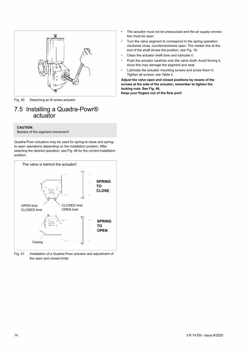
7.5 Installing a Quadra-Powr® actuator
Quadra-Powr actuators may be used for spring-to-close and spring-to-open operations depending on the installation position. After selecting the desired operation, see Fig. 46 for the correct installation position.
• The actuator must not be pressurized and the air supply connec-tion must be open.
• Turn the valve segment to correspond to the spring operation: clockwise close, counterclockwise open. The marker line at the end of the shaft shows the position, see Fig. 16.
• Clean the actuator shaft bore and lubricate it.• Push the actuator carefully onto the valve shaft. Avoid forcing it,
since this may damage the segment and seat.• Lubricate the actuator mounting screws and screw them in.
Tighten all screws, see Table 4.Adjust the valve open and closed positions by means of the screws at the side of the actuator; remember to tighten the locking nuts. See Fig. 46.Keep your fingers out of the flow port!
Fig. 40 Detaching an B series actuator
CAUTION:Beware of the segment movement!
Fig. 41 Installation of a Quadra-Powr actuator and adjustment of the open and closed limits
SPRINGTOCLOSE
SPRINGTOOPEN
The valve is behind the actuator!
OPEN limitCLOSED limit
CLOSED limitOPEN limit
Casing
14 3 R 74 EN - Issue 9/2020

8 TROUBLE SHOOTING TABLE
Table 6 lists malfunctions that might occur after prolonged use.
Table 4 Trouble shooting
9 TOOLSIn addition to standard tools the following special tools might be needed to facilitate working.• For removal of the actautor
• For mounting and removal of the seat.
• Shaft position checking (low Cv valves)- former H069563 (Series RA)- former H069564 (Series RE, RE1)
These are available from the manufacturer.
10 ORDERING SPARE PARTS
When ordering spare parts, always include the following information:• type code, sales order number, serial number (stamped on a
valve body)• number of the parts list, part number, name of the part and quan-
tity requiredThis information can be found from the identification plate or documents.
Symptom Possible fault Recommended action
Leakage through a closed valve
Wrong stop screw adjustment of the actuator Adjust the stop screw for closed position
Faulty zero setting of the positioner Adjust the positioner
Damaged seat Replace seat
Damaged closing member Replace the closing member
Closing member in a wrong position relative to the actuator Select the correct keyway in the actuator
Leakage through body jointDamaged gasket Replace the gasket
Loose body joint Tighten the nuts or screws
Irregular valve movements
Actuator or positioner malfunction Check the operation of the actuator and positioner
Process medium accumulated on the sealing surface Clean the sealing surfaces
Closing member or seat damaged Replace the closing member or seat
Crystallizing medium has entered the bearing spaces Flush the bearing spaces
Gland packing leakingGland packing worn or damaged Replace the gland packing
Loose packing Tighten the packing nuts
Product: ID:
B1C/B1J 6 303821
B1C 8-11 / B1J 8-10 8546-1
B1C 12-17 / B1J 12-16 8546-2
B1C/B1J 20 8546-3
B1C/B1J 25 8546-4
B1C/B1J 32 8546-5
B1C 40 / B1J 322 8546-6
B1C 50 8546-7
B1C 502 8546-8
Product: ID:
DN 01 273336
DN 015 273337
DN 02 273338
DN 03 273339
DN 04 273340
DN 06 273341
DN 08 273342
DN 10 273343
DN 12 273344
NOTE:Always use original spare parts to make sure that the valve functions as intended.
3 R 74 EN - Issue 9/2020 15

11 EXPLODED VIEWS AND PARTS LISTS11.1 Series RA
Spare part set category: Recommended soft parts, always needed for the repair. Delivered as a set.Spare part category 2: Parts for replacing of the seat. Delivered as a set.Spare part category 3: Parts for replacing of the closing element.Spares for the full overhaul: All parts from the categories 1, 2 and 3.
RA025 - 100
RA150 - 250
26 10 19 17
1 35 35
4
4 5 6
12 14 3 1511
134 5 6 30
925
16 32 31
20 31
22
E SEAT
S SEAT
T SEAT
Item Qty. Description Spare part category
1 1 Body
3 1 Segment 3
4 1 Seat 2
5 1 Lock spring 2
6 1 Back seal 2
9 1 Gland follower
10 1 Blind flange
11 1 Drive shaft 3
12 1 Shaft 3
13 1 Key 3
14 1 Cylindrical pin 3 (Cat. 2 for sizes 01"–02")
15 1 Cylindrical pin 3 (Cat. 2 for sizes 01"–02")
16 1 Bearing 3
17 1 Bearing 3
19 1–2 Sealing plate 1
20 1 Packing 1
22 1 Filling ring (only in new low Cv version)
25 2–4 Countersunk screw
26 4 Hexagon screw
30 2 Retainer ring
31 2 Sheet ring
32 1 Wave spring
35 1 Identification plate
16 3 R 74 EN - Issue 9/2020
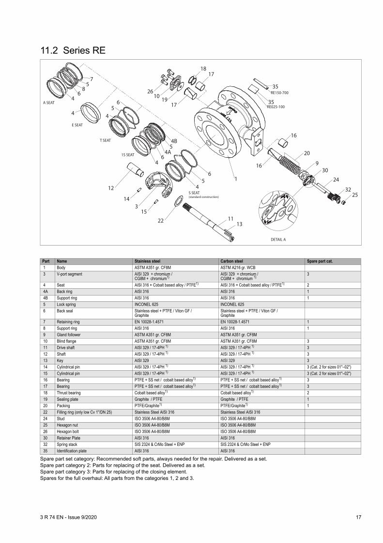
11.2 Series RE
Spare part set category: Recommended soft parts, always needed for the repair. Delivered as a set.Spare part category 2: Parts for replacing of the seat. Delivered as a set.Spare part category 3: Parts for replacing of the closing element.Spares for the full overhaul: All parts from the categories 1, 2 and 3.
A SEAT
E SEAT
T SEAT
1S SEAT
S SEAT(standard construction)
75
86
4
4
65
4
4B5
4A6
4
12
14
15
22
3
1311
2532
24
30
20
16
16
35
3517
17
1
1910
26
45
6
9
RE150-700
RE025-100
18
DETAIL A
Part Name Stainless steel Carbon steel Spare part cat. 1 Body ASTM A351 gr. CF8M ASTM A216 gr. WCB
3 V-port segment AISI 329 + chromium / CG8M + chromium1)
AISI 329 + chromium / CG8M + chromium 1)
3
4 Seat AISI 316 + Cobalt based alloy / PTFE1) AISI 316 + Cobalt based alloy / PTFE1) 2 4A Back ring AISI 316 AISI 316 1
4B Support ring AISI 316 AISI 316 1
5 Lock spring INCONEL 625 INCONEL 625 6 Back seal Stainless steel + PTFE / Viton GF /
GraphiteStainless steel + PTFE / Viton GF /Graphite
7 Retaining ring EN 10028-1.4571 EN 10028-1.4571 1 8 Support ring AISI 316 AISI 316 1
9 Gland follower ASTM A351 gr. CF8M ASTM A351 gr. CF8M
10 Blind flange ASTM A351 gr. CF8M ASTM A351 gr. CF8M 3 11 Drive shaft AISI 329 / 17-4PH 1) AISI 329 / 17-4PH 1) 3
12 Shaft AISI 329 / 17-4PH 1) AISI 329 / 17-4PH 1) 3
13 Key AISI 329 AISI 329 3 14 Cylindrical pin AISI 329 / 17-4PH 1) AISI 329 / 17-4PH 1) 3 (Cat. 2 for sizes 01"–02")
15 Cylindrical pin AISI 329 / 17-4PH 1) AISI 329 / 17-4PH 1) 3 (Cat. 2 for sizes 01"–02")
16 Bearing PTFE + SS net / cobalt based alloy1) PTFE + SS net / cobalt based alloy1) 3 17 Bearing PTFE + SS net / cobalt based alloy1) PTFE + SS net / cobalt based alloy1) 3
18 Thrust bearing Cobalt based alloy1) Cobalt based alloy1) 2
19 Sealing plate Graphite / PTFE Graphite / PTFE 1 20 Packing PTFE/Graphite1) PTFE/Graphite1) 1
22 Filling ring (only low Cv 1"/DN 25) Stainless Steel AISI 316 Stainless Steel AISI 316
24 Stud ISO 3506 A4-80/B8M ISO 3506 A4-80/B8M 25 Hexagon nut ISO 3506 A4-80/B8M ISO 3506 A4-80/B8M
26 Hexagon bolt ISO 3506 A4-80/B8M ISO 3506 A4-80/B8M
30 Retainer Plate AISI 316 AISI 316 32 Spring stack SIS 2324 & CrMo Steel + ENP SIS 2324 & CrMo Steel + ENP
35 Identification plate AISI 316 AISI 316
3 R 74 EN - Issue 9/2020 17

12 DIMENSIONS AND WEIGHTS12.1 Series RA
øDDN
A
A1
øB
CK
E
A A
R
øO
P
Dimensions of mountinglevel acc. to ISO 5211
M
A - A
(L)
øU1øU2
øS1øS2
V
V
øZ
Type DN ISO 5211
Dimensions, mmkg
A1 A øB C øD E R K øO M P øS1 øS2 øU1 øU2 øZ L V
RA
25 F05 21 50 64 56 33 127 27 102 15 4.76 17 - 50 - 6.6 35 15.5 52 1.3
40 F05 21 60 82 65 49 133.5 25 108.5 15 4.76 17 - 50 - 6.6 35 15.5 52 2.4
50 F05, F07 27 75 100 91 60 144.5 25 119.5 15 4.76 17 70 50 9 6.6 55 15.5 67 3.7
65 F05, F07 40 100 118 97 75 151 25 126 15 4.76 17 70 50 9 6.6 55 15.5 67 5.3
80 F07, F10 38 100 130 108 89 177 35 142 20 4.76 22.2 102 70 11 9 70 16 94 6.2
100 F07, F10 41 115 158 120 115 186 35 151 20 4.76 22.2 102 70 11 9 70 16 94 9.6
150 F10, F12 55 160 216 174 164 244 44 200 25 6.35 27.8 125 102 14 11 85 22 114 24
200 F10, F12 70 200 268 201 205 285 50 235 30 6.35 32.9 125 102 14 11 85 22 114 42
250 F12, F14 82 240 324 251 259 338 61 277 35 9.53 39.1 140 125 18 14 100 26 136 68
18 3 R 74 EN - Issue 9/2020

12.2 RA-B1C
1) Max Δp in on-off service with actuator load factor 0.6 and supply pressure 5 bar
FLOW DIRECTION
C
H
DN
øD
MOUNTING POSITION A-VU (STANDARD)
øB
V
A
NPT
FG
I max
J
X
A1SUPPLY 1/4 NPT
SIGNAL M20 X 1.5 CABLE GLAND
NPT
Type Max Δp1)
Dimensions, mmNPT kg
DN A A1 øB C øD F G X V J H Imax
RA_025-B1C6 50 25 50 21 64 56 33 400 260 90 36 168 305 310 1/4 5,5
RA_040-B1C6 50 40 60 21 82 65 49 400 260 90 36 175 320 310 1/4 6,6
RA_050-B1C6 50 50 75 27 100 91 60 400 260 90 36 185 355 310 1/4 8
RA_050-B1C9 50 50 75 27 100 91 60 455 315 110 43 185 365 305 1/4 13,5
RA_065-B1C6 50 65 100 40 118 97 75 400 260 90 36 192 367 310 1/4 9,5
RA_065-B1C9 50 65 100 40 118 97 75 455 315 110 43 192 380 305 1/4 15
RA_080-B1C6 50 80 100 38 130 108 89 400 260 90 36 200 390 310 1/4 11
RA_080-B1C9 50 80 100 38 130 108 89 455 315 110 43 200 400 305 1/4 16
RA_100-B1C6 40 100 115 41 158 120 115 400 260 90 36 210 410 310 1/4 15
RA_100-B1C9 40 100 115 41 158 120 115 455 315 110 43 210 420 305 1/4 19
RA_150-B1C9 25 150 160 55 216 174 164 455 315 110 43 260 515 305 1/4 34
RA_150-B1C11 40 150 160 55 216 174 164 540 375 135 51 265 530 310 3/8 40
RA_150-B1C13 40 150 160 55 216 174 164 635 445 175 65 280 550 325 3/8 55
RA_200-B1C9 15 200 200 70 268 201 205 455 315 110 43 294 575 305 1/4 52
RA_200-B1C11 32 200 200 70 268 201 205 540 375 135 51 310 590 310 3/8 59
RA_200-B1C13 35 200 200 70 268 201 205 635 445 175 65 325 610 325 3/8 73
RA_250-B1C13 30 250 240 82 324 251 259 635 445 175 65 366 730 325 3/8 100
RA_250-B1C17 35 250 240 82 324 251 259 770 545 215 78 373 750 340 3/8 125
3 R 74 EN - Issue 9/2020 19

12.3 RA - B1J, B1JA
1) Supply pressure BJ 4 bar / BJA 5 bar
F
V
øB
NPT
J
H
C
FLOW DIRECTION
MOUNTING POSITION A-VU (STANDARD)
øD
DN
A1A
I max
G
X
SUPPLY 1/4 NPT
SIGNAL M20 X 1.5 CABLE GLAND
NPT
Type Max Δp1)
Dimensions, mmNPT kg
DN A A1 øB C øD F G X V J H Imax
RA_025-B1J6 50/50 25 50 21 64 56 33 485 368 110 36 166 291 280 3/8 14
RA_040B1J6 50/50 40 60 21 82 65 49 485 368 110 36 173 306 280 3/8 15
RA_050-B1J6 50/50 50 75 27 100 91 60 485 368 110 36 183 343 280 3/8 16
RA_065-B1J6 50/50 65 100 40 118 97 75 485 368 110 36 193 358 280 3/8 18
RA_080B1J6 50/50 80 100 38 130 108 89 485 368 110 36 198 374 280 3/8 19
RA_100-B1J6 50/50 100 115 41 158 120 113 485 368 110 36 208 398 280 3/8 22
RA_025-B1J8/B1JA8 50/50 25 50 21 64 56 33 555 420 135 43 168 293 305 3/8 19
RA_040-B1J8/B1JA8 50/50 40 60 21 82 65 49 555 420 135 43 175 308 305 3/8 20
RA_050-B1J8/B1JA8 50/50 50 75 27 100 91 60 555 420 135 43 185 345 305 3/8 21
RA_065-B1J8/B1JA8 50/50 65 100 40 118 97 75 555 420 135 43 195 360 305 3/8 23
RA_080-B1J8/B1JA8 50/50 80 100 38 130 108 89 555 420 135 43 200 376 305 3/8 24
RA_100-B1J8/B1JA8 50/50 100 115 41 158 120 113 555 420 135 43 210 400 305 3/8 27
RA_150-B1J8/B1JA8 10/25150 160 55 216 174 164
555 420 135 43 258 500 305 3/8 41
RA_150-B1J10/B1JA10 40/40 650 490 175 51 275 530 225 3/8 55
RA_200-B1J10/B1JA10 15/25200 200 70 268 201 205
650 490 175 51 310 590 310 3/8 75
RA_200-B1J12/B1JA12 32/35 800 620 215 65 324 635 235 1/2 100
RA_250-B1J16/B1JA16 35/35 250 240 85 324 251 259 990 760 265 78 373 760 340 1/2 170
20 3 R 74 EN - Issue 9/2020

12.4 RA - M
*) Actuators equipped with extended input shaft.**) Actuators M07...M12 are equipped with handwheel type SR, actuators M14...M16 are equipped with handwheel type R.
øB
øD
J
DN
H
C
A
G
F
R
**)
SR
øZ
V
TypeActuator/mountingISO 5211
DNDimensions, mm
kgøD A A1 øB C F G H J V øZ
RA
M07/15F05 25 33/38* 50 21 64 56 235 184 223 131 52 160 5.1
M07/15F05 40 49 60 21 82 65 235 184 238 137 52 160 6.2
M07/15F05 50 60 75 27 100 91 235 184 275 148 52 160 7.5
M07/15F05 65 75 100 40 118 97 235 184 288 155 52 160 9.5
M07/20F07 80 89 100 38 130 108 235 184 315 171 52 160 10
M07/20F07 100 115 115 41 158 120 235 184 336 180 52 160 14
M10/25F10 150 164 160 55 216 174 238 187 439 235 52 200 29
M12/30F12 200 205 200 70 268 201 307 238 524 276 71 315 52
M12/35F12 250 259 240 82 324 251 307 238 616 318 71 315 78
M14/35F12 250 259 240 82 324 251 385 285 621 320 86 400 87
3 R 74 EN - Issue 9/2020 21

12.5 Series REDN150...500DN25...100
RE_ A DN25...700
(KEY)(SPLINES)
RE_E DN25...400
DN600...700
DN
E
R
(L)
ØD
ØB
K
N
PØO
S
U
S
M
U
T
H
M
N1
K
E1
R1HP1
ØO1
S
S2
M
T
U
A1
Valve is shown in closed position
C
A
DN / inchDimensions, mm Shaft dimensions, mm
A1 A C ØD K S/S2 T U L HRE_A (Key) RE_E (Splines)
E R ØO M P N E1 R1 ØO1 P1/DIN5480 N125 / 1" 51 102 56 33 182 70 - M10 15.5 80 207 105 15 4.76 17 25 203 101 15 W14x1x12 20
40 / 1 1/2" 57 114 65 49 188.5 70 - M10 15.5 80 213.5 105 15 4.76 17 25 209.5 101 15 W14x1x12 2050 / 2" 62 124 91 60 199.5 70 - M10 15.5 80 224.5 105 15 4.76 17 25 219.5 100 15 W14x1x12 20
65 / 2 1/2" 72.5 145 97 75 206 70 - M10 15.5 80 231 105 15 4.76 17 25 226 100 15 W14x1x12 2080 / 3" 82.5 165 108 89 232 90 - M12 16 90 267 125 20 4.76 22.2 35 253 111 20 W14x1x12 20100 / 4" 97 194 120 113 241 90 - M12 16 90 276 125 20 4.76 22.2 35 262 111 20 W18x1x16 20150 / 6" 114.5 229 174 164 290 110 32 M12 22 90 335 135 25 6.35 27.8 46 315 115 25 W25x1x24 25200 / 8" 111.5 243 201 205 345 130 32 M12 22 110 395 160 30 6.35 32.9 51 370 135 30 W25x1x24 25
250 / 10" 138.5 297 251 259 387 130 32 M12 26 110 445 168 35 9.53 39.1 58 422 145 35 W34x1x32 35300 / 12" 154 338 269 300 417 160 40 M16 26 120 485 188 40 9.53 44.2 68 452 155 40 W34x1x32 35350 / 14" 175 400 311 350 433 160 40 M16 29 120 513 200 45 12.70 50.4 80 468 155 45 W34x1x32 35400 / 16" 160 400 353 400 494 160 55 M20 29 140 584 230 50 12.70 55.5 90 529 175 50 W34x1x32 35500 / 20" 233 508 420 500 615 230 90 M27 40 180 727 292 70 19.05 78.2 119 - - - - -600 / 24'' 355 610 490 600 704 330/304.7 120 M30 40 220 838 354 75 19.05 81.9 134 - - - - -700 / 28'' 295 710 539 700 768 330/304.7 120 M30 55 220 914 366 85 22.225 95.3 146 - - - - -800 / 32'' 380 840 635 800 871.5 330/304.7 120 M30 55 220 1052 402 105 25.4 114.4 180 - - - - -
DN / inchFlange dimensions, mm, and weights
REC ASME 150 RED ASME 300 REJ PN10 REK PN16 REL PN25 REM PN40B kg B kg B kg B kg B kg B kg
25 / 1" 110 3.6 125 4.9 115 4.6 115 4.6 115 4.6 115 4.640 / 1 1/2" 125 4.6 155 7.5 150 6.2 150 6.2 150 6.2 150 6.2
50 / 2" 150 7.4 165 9.5 165 8.8 165 8.8 165 8.8 165 8.865 / 2 1/2" 180 13 190 13 185 13 185 13 185 13 185 13
80 / 3" 190 14 210 19 200 16 200 16 200 16 200 16100 / 4" 230 21 255 29 220 18 220 18 235 21 235 21150 / 6" 280 39 320 54 285 37 285 37 300 42 300 42200 / 8" 345 62 380 83 340 56 340 60 360 64 375 71
250 / 10" 405 95 445 132 395 90 405 91 425 101 450 125300 / 12" 485 143 520 203 445 124 460 130 485 166 515 189350 / 14" 535 194 585 290 505 174 520 182 555 248 580 275400 / 16" 595 249 650 364 565 223 580 235 620 314 660 361500 / 20" 700 453 775 595 670 375 715 468 730 486 755 549600 / 24'' 815 853 915 1051 780 791 840 899 845 910 890 1007700 / 28'' 925 1260 1035 1535 895 1134 910 1146 960 1243 1145 1338800 / 32'' 1060 1850 1150 - 1102 1550 1025 1570 1085 1790 - -
22 3 R 74 EN - Issue 9/2020

12.6 RE - B1C
1) Max Δp in on-off service with actuator load factor 0.6 and supply pressure 5 bar*) 38 mm for low capacity segment eg. C005-RE_
A
V
øD
DN
C J
H
I
X
GF
NPT
NPT
øB
MOUNTING POSITION A (STANDARD)
FLOW DIRECTION
SIGNAL M20 X 1.5 CABLE GLAND
SUPPLY 1/4 NPT
b 1
Type MaxΔp1)
Dimensions, mmNPT
REJ_ PN 10 REK_ PN 16 REL_ PN 25 REM_ PN 40 REC_ ASME 150 RED_ ASME 300NPS DN A C øD F G X V J H Imax øB b1 kg øB b1 kg øB b1 kg øB b1 kg øB b1 kg øB b1 kg
RE_ 01-B1C6 50 1 25 102 56 33/38* 400 260 90 36 240 341 310 1/4 115 18 11.9 115 18 11.9 115 18 11.9 115 18 11.9 108 18 11.9 124 18 11.9RE_ 1H-B1C6 50 1.5 40 114 65 49 400 260 90 36 247 357 310 1/4 150 18 13.5 150 18 13.5 150 18 13.5 150 18 13.5 127 18 13.5 155 18 14.3RE_ 02-B1C6 50 2 50 124 91 60 400 260 90 36 258 394 310 1/4 165 20 16.1 165 20 16.1 165 20 16.1 165 20 16.1 152 20 16.1 165 20 16.8RE_ 2H-B1C6 50 2.5 65 145 97 75 400 260 90 36 265 410 310 1/4 185 22 18 185 22 18 185 22 18 185 22 18 185 22 18 - - -RE_ 03-B1C6 50 3 80 165 108 89 400 260 90 36 290 443 310 1/4 200 20 23 200 20 23 200 24 23 200 24 23 191 24 21 210 24 26RE_04-B1C6 40 4 100 194 120 113 400 260 90 36 299 464 310 1/4 220 20 25.3 220 20 25.3 235 24 28.3 235 24 28.3 229 24 28.3 254 24 34.3RE_06-B1C6RE_06-B1C9
RE_06-B1C11
102540
6150 229 174 164 400
455540
260315375
90110135
364365
348349355
567578597
310305310
1/41/43/8
285 22 44.35057
285 22 44.35057
300 28 49.35562
300 28 49.35562
279 28 46.35259
318 28 51.35764
RE_08-B1C6RE_08-B1C9
RE_08-B1C11
41532
8200 243 201 205 400
455540
260315375
90110135
364351
403404410
649660679
310305310
1/41/43/8
340 24 637077
340 24 677380
360 30 717784
375 34 788491
343 30 697582
381 34 9096
103RE_10-B1C9
RE_10-B1C11RE_10-B1C13RE_10-B1C17
7152935
10
250 297 251 259 455540635770
315375445545
110135175215
43516578
446452468483
752771807842
310310325340
1/43/83/81/2
405 26 99106121144
405 26 99106121144
425 32 115122137160
450 38 139146161184
406 32 104114139162
450 38 152159174197
RE_12-B1C11RE_12-B1C13RE_12-B1C17
71930
12300 338 269 300 540
635770
375445545
135175215
516578
482498513
819855890
310325340
3/83/81/2
460 26 144159182
460 28 144159182
485 34 168183206
520 42 202217240
483 34 162177200
520 42 219234257
RE_14-B1C13RE_14-B1C17RE_14-B1C20
92127
14350 400 311 350 635
770840
445545575
175215215
657897
514529548
913947967
325340355
3/81/21/2
505 26 213236255
520 30 218241260
555 38 258281300
580 46 301324343
534 38 238261280
584 46 319342361
RE_16-B1C17RE_16-B1C20RE_16-B1C25
152130
16400 400 353 400 770
8401075
545575725
215215265
7897121
590609632
105110711118
340355390
1/21/21/2
565 26 293312370
580 32 298317375
620 40 349368426
660 50 405424482
597 40 323342400
648 50 414433491
RE_20-B1C25 16 20 500 508 430 500 1075 725 265 121 723 1286 390 1/2 670 26 547 715 42 566 730 46 661 755 57 552 700 41,3 562 775 64 584RE_24-B1C25RE_24-B1C32
919 24 600 610 497 600 1075
1370725920
265395
121153
842879
14981573
390430
1/23/4
780 28 10341159
840 40 11051230
845 46 11651290
890 60 11711296
815 46,1 11001225
915 68,3 12981423
RE_28-B1C32RE_28-B1C40
1023 28 700 710 547 700 1370
16709201150
395505
153194
944993
16861756
430450
3/43/4
895 30 13451535
910 42 13861576
960 50 14671657
995 64 15801770
925 69,9 15061696
1035 88,9 17701960
3 R 74 EN - Issue 9/2020 23

12.7 RE - B1J, B1JA
1) Supply pressure BJ 4 bar / BJA 5 bar*) 38 mm for low capacity segment eg. C005-RE_
A
V
øD
DN
C J
H
I
X
GF
NPT
øB
FLOW DIRECTION
MOUNTING POSITION A (STANDARD)
SIGNAL M20 X 1.5 CABLE GLAND
SUPPLY 1/4 NPT
NPT
b 1
Type MaxΔp1)
Dimensions, mmNPT
REJ_ PN10 REK_ PN16 REL_ PN25 REM_ PN40 REC_ ASME 150
RED_ ASME 300
NPS DN A C øD F G X V J H Imax øB b1 kg øB b1 kg øB b1 kg øB b1 kg øB b1 kg øB b1 kg
RE_01-B1J6 50/50 1 25 102 56 33/38* 485 368 110 36 238 362 305 3/8 115 18 20 115 18 20 115 18 20 115 18 20 108 18 20 124 18 20
RE_1H-B1J6 50/50 1,5 40 114 65 49 485 368 110 36 245 378 305 3/8 150 18 22 150 18 22 150 18 22 150 18 22 127 18 22 155 18 23RE_02-B1J6 50/50 2 50 124 91 60 485 368 110 36 256 414 305 3/8 165 20 24 165 20 24 165 20 24 165 20 24 152 20 24 165 20 25RE_2H-B1J6 50/50 2,5 65 145 97 75 485 368 110 36 263 428 305 3/8 185 22 25 185 22 25 185 22 25 185 22 25 185 22 25 - - -RE_03-B1J6 50/50 3 80 165 108 89 485 368 110 36 288 464 305 3/8 200 20 31 200 20 31 200 24 31 200 24 31 191 24 29 210 24 34RE_04-B1J6 50/50 4 100 194 120 113 485 368 110 36 297 485 305 3/8 220 20 33 220 20 33 235 24 36 235 24 36 229 24 37 254 24 42
RE_01-B1J8/B1JA8 50/50 1 25 102 56 33/38* 560 420 135 43 240 364 305 3/8 115 18 25 115 18 25 115 18 25 115 18 25 108 18 25 124 18 25
RE_1H-B1J8/B1JA8 50/50 1,5 40 114 65 49 560 420 135 43 247 380 305 3/8 150 18 27 150 18 27 150 18 27 150 18 27 127 18 27 155 18 28RE_02-B1J8/B1JA8 50/50 2 50 124 91 60 560 420 135 43 258 416 305 3/8 165 20 29 165 20 29 165 20 29 165 20 29 152 20 29 165 20 30RE_2H-B1J8/B1JA8 50/50 2,5 65 145 97 75 560 420 135 43 265 430 305 3/8 185 22 30 185 22 30 185 22 30 185 22 30 185 22 30 - - -RE_03-B1J8/B1JA8 50/50 3 80 165 108 89 560 420 135 43 290 466 305 3/8 200 20 36 200 20 36 200 24 36 200 24 36 191 24 34 210 24 39RE_04-B1J8/B1JA8 50/50 4 100 194 120 113 560 420 135 43 299 487 305 3/8 220 20 38 220 20 38 235 24 41 235 24 41 229 24 42 254 24 47RE_06-B1J8/B1JA8
RE_06-B1J10/B1JA1010/2540/40 6 150 229 174 164 560
650420490
135175
4351
348355
590617
305225
3/83/8 285 22 57
70 285 22 5770 300 28 62
75 300 28 6275 279 28 59
72 318 28 6577
RE_08-B1J8/B1JA8RE_08-B1J10/B1JA10RE_08-B1J12/B1JA12
- /1215/2532/35
8 200 243 201 205560650800
420490620
135175215
435165
404410426
673700736
305310235
3/83/81/2
340 247690
118340 24
8093120
360 308497
124375 34
91104132
343 308295
123381 34
103116144
RE_10-B1J10/B1JA10RE_10-B1J12/B1JA12RE_10-B1J16/B1JA16
5/1520/2535/35
10 250 297 251 259650800990
490620760
175215265
516578
452468483
790827867
310325340
3/81/21/2
405 26119147200
405 26119147200
425 32135163216
450 38159187240
406 32124145218
450 38172200253
RE_12-B1J12/B1JA12RE_12-B1J16/B1JA16RE_12-B1J20/B1JA20
8/1820/2530/30
12 300 338 269 3008009901200
620760935
215265395
657897
498513534
8759161000
325340270
1/21/23/4
460 26185228303
460 28185228303
485 34209252327
520 42243217361
483 34203246321
520 42260303378
RE_14-B1J16/B1JA16RE_14-B1J20/B1JA20
11/2230/30 14 350 400 311 350 990
1200760935
265395
7897
529548
9731057
340355
1/23/4 505 26 282
357 520 30 287362 555 38 327
402 580 46 370445 534 38 307
382 584 46 388463
RE_16-B1J20/B1JA20RE_16-B1J25/B1JA25
19/2530/30 16 400 400 353 400 1200
15309351200
395505
97121
609632
11611238
355390
3/43/4 565 26 414
590 580 32 419595 620 40 470
646 660 50 526702 597 40 444
620 648 50 535711
RE_20-B1J25/B1JA25 25/25 20 500 508 430 500 1530 1200 505 121 723 1406 390 1/2 670 47 720 715 47 720 730 47 825 755 57 596 699 47 720 775 62 628RE_24-B1J32/B1JA32 18/18 24 600 610 497 600 1885 1435 540 153 879 1577 427 1 780 28 1574 840 40 1645 845 46 1705 890 60 1711 815 46.1 1640 915 68.3 1838RE_28-B1JV32/B1JVA32 13/13 28 700 710 547 700 1885 1435 540 153 943 1691 427 1 895 30 1760 910 42 1801 960 50 1882 995 64 1995 925 69.9 1921 1035 88.9 2185
24 3 R 74 EN - Issue 9/2020

12.8 RE - QPX
3/8 NPT E Springtoopen
SIGNAL 1/4 NPT
SUPPLY 1/4 NPT
ESpringtoclose
FLOW DIRECTION
A
X
GF
K
J
H
I
max outside diaof pipe
d
DN ActuatorQPX
Max shut-off Δp barRE, Q-RE
Max control Δp bar
RE
Max control Δp barQ-RE
Dimensions, mmTotal weight, kg
Valve+actuator+positioner
A E F G H I J K X Pipe d ASME 150 ASME 300
25 1 50 35 - 102 142 382 330 388 160 225 182 213 230 19 20,5
40 1 50 35 - 114 142 382 330 404 160 232 189 213 245 20 23
50 1 50 35 35 124 142 382 330 441 160 243 200 213 265 22 25
80 2 35 25 18 165 142 382 330 506 172 284 232 213 330 38 43
100 2 35 25 18 194 156 480 389 527 172 293 241 228 350 45 53
150 23
2840
2525
1818
229229
156190
480565
389446
630657
191214
342346
290290
228274
450410
6378
7893
200 34
1635
1625
1515
243243
190228
565635
446495
739768
191214
401407
345345
274320
520485
101121
122142
250 45
2035
2020
1010
297297
228276
635768
495608
860906
214243
449464
387387
320382
570540
150205
198253
300 5 25 10 8 338 276 768 608 982 214 522 445 382 650 256 313
350 5 12 10 8 400 276 768 608 1065 243 563 486 382 735 317 398
400 5 8 8 8 400 276 768 608 1174 243 630 553 382 870 378 470
3 R 74 EN - Issue 9/2020 25

12.9 Suitability with different flanges,RA and RE1 valves
x = suitable with this flange- = not suitable with this flange
12.10 Flange ratings, RE(Class 150, 300)
See 12.3 for guidance.Note: Class 600 RE with full rated valve body.
FlangeValve size
DN 25 / 01 DN 40 / 01H DN 50 / 02 DN 65 DN 80 / 03 DN 100 /04 DN 150 / 06 DN 200 / 08 DN 250
ASME B16.5 Class 150 x x x x x x x x x
ASME B16.5 Class 300 x x x x x x x x -
PN 40 x x x x x x x - x
PN 25 x x x x x x x x x
PN 16 x x x x x x x x x
PN 10 x x x x x x x x x
ISO 7005 PN 20 x x x x x x x x x
ISO 7005 PN 50 x x x x x x x x -
JIS 2238 10K x x x x x x x x x
JIS 2238 16K x x x x x x x x x
JIS 2238 20K x x x x x x x x x
JIS 2238 30K x x x x x x x x x
Size PN 10 PN 16 PN 25 PN 40
025* equal to PN 40 equal to PN 40 equal to PN 40 M
040* equal to PN 40 equal to PN 40 equal to PN 40 M
050* equal to PN 40 equal to PN 40 equal to PN 40 M
065 equal to PN 16 K equal to PN 40 M
080* equal to PN 40 equal to PN 40 equal to PN 40 M
100* equal to PN 16 K equal to PN 40 M
150* equal to PN 16 K equal to PN 40 M
200 J K L M
250 J K L M
300 J K L M
350 J K L M
400 J K L M
500 J K L M
600 J K L M
700 J K L -
800 J K L -
26 3 R 74 EN - Issue 9/2020

13 TYPE CODE13.1 Series RA
Low Cv + metal seat: segment material AISI 316 + HCr.Low Cv + soft seat: segment material AISI 316 (without HCr).
V-port segment valve, series RA
1. 2. 3. 4. 5. 6. 7.
RA A 100 A S _
1. CV-CODE FOR VALVE SIZE DN 25 (01")
STANDARD CV
Without sign
Q-TRIM
Q Low noise and anti-cavitation trim
NON-STANDARD CV
C005- Max. Cv = 0.5
C015- Max. Cv = 1.5
C05- Max. Cv = 5.0
C15- Max. Cv = 15.0
2. PRODUCT SERIES / DESIGN
RA Wafer, reduced bore, Neles face-to-face lenght, body PN 40* / ASME Class 300**.
* DN 250 body only acc. to EN PN 40. **Max. shut-off pressure for trim, see Table 1.
3. CONSTRUCTION
A Standard, drive shaft with keyway
Y Special
4. SIZE
In millimetres:025, 040, 050, 065, 080, 100, 150, 200, 250
5. BODY SEGMENT SCREWS SHAFT, PINS /BEARINGS
A CF8M AISI 329 + HCr A2-70 AISI 329 / PTFE
C CG8M AISI 329 + HCr A2-70 AISI 329 / PTFE
H(with
T6 seat)
CW-6M(Hastelloy C) CW-6M A2-70 Hastelloy C /
PVDF
S(with
T2 seat)CF8M AISI 329 A2-70 AISI 329 / PTFE
U(with
U seat)
CK3MCuN(SMO)
ASTM A351gr. CK3MCuN+ ceramic coating (TiO)
A2-70
UNS31254 / filledPTFE on SMO 254 net
Seals for above: Gland packing: Blind flange:
PTFE V-ring typePTFE
Y Special
6. SEAT MATERIAL AND CONSTRUCTION
S Stainless steel + Cobalt Hard facing, -40 °C to +260 °C.1-way tight metal seat, for NPS 1" - 10" / DN 25 - 250
1S Stainless steel + Cobalt Hard facing, -30 °C to +200 °C.2-way tight metal seat, for NPS 1" - 10" / DN 25 - 250.
T2 Stainless steel with PTFE+C25, -40 °C to +260 °C.
T6 Hastelloy with Xtreme insert, -40 °C to +120 °C.
E Cobalt based alloy, -50 °C to +260 °C.Non-tight, extremely erosive services.
U Titanium, -40 °C to +120 °C.
7. FLANGE FACING
STANDARD
Without sign: EN1092-1 Type B1 (Ra 3.2 ... 12.5)Covers:DIN2526 form C DIN2526 form DRaised face stock finished (Ra10...12.5)
NON-STANDARD
/Y Special
3 R 74 EN - Issue 9/2020 27

13.2 Series RE, RE1
V-port segment valve, series RE and RE1
1. 2. 3. 4. 5. 6. 7. 8. 9. 10. 11. 12.
Q- RE D A 03 D J J S T A / -
1. CV-CODE
Standard V-port (without sign)
Q- Q-trim, low noise and anti-cavitation trim. (for DN 50 / 2" and bigger)
C005- Max. Cv = 0.5 (for DN 25 / 1" only)
(Not with 1S-seat)C015- Max. Cv = 1.5 (for DN 25 / 1" only)
C05- Max. Cv = 5 (for DN 25 / 1" only)
C15- Max. Cv = 15 (for DN 25 / 1" only)
2. PRODUCT SERIES / DESIGN
RE Flanged, one piece body, V-port segmented ball, face-to-face acc. to ISA S75.04 and IEC Part 3-2. Inch threads.
RE1 Flangeless one piece body, V-port segmented ball, face-to-face acc. to ISA S75.04 and IEC 534 Part 3-2.
RE13 Flanged body, V-port segmented ball face-to-face acc. to ASME B16.10 (spool piece constr.).
3. PRESSURE RATING Size range
C ASME 150 NPS 1" - 32"
D ASME 300 NPS 1" - 32"
F ASME 600 NPS 1"
J PN 10 DN 200 - DN 800
K PN 16 DN 50 - DN 800
L PN 25 DN 200 - DN 800
M PN 40 DN 25 - DN 600
R JIS 10K flanges, based on body casting of ASME 150 DN 25 – DN 800
S JIS 16K flanges, based on body casting of ASME 300 DN 25 – DN 800
T JIS 20K flanges, based on body casting of ASME 300 DN 25 – DN 800
Y Special, to be specified -
4. CONSTRUCTION
A Standard, (2-way tight with 1S-seat)
B Low emission construction (ISO 15848-1; Class BH, CC-3 / temp: 260 °C, Class BH CC-2 / temp: 400 °C)
E Drive shaft with splines to actuator
U Protected bearings (Viton GF O- rings) (*
V Hydrogen Peroxide (H2O2) construction.
X Antistatic device (*
S Steam jacket (for DN 25 - 50 / NPS 1" - 2") consult the factory.
Z
Oxygen construction, only for Gaseous Oxygen Service.- BAM listed non-metallic materials- Temperature: +200 °C to -50 °C- Cleaning acc. to Neles internal procedureRecommended type code: RE_Z__AJJSG
Y Special, to be specified
5. SIZE
ASME EN
01 ASME flanged, 150, 300and 600 025 EN flanged, PN 40
1H ASME flanged, 150 and 300 040 EN flanged, PN 40
02 ASME flanged, 150 and 300 050 EN flanged, PN 40
2H ASME flanged, 150 and 300 065 EN flanged, PN16, 40
03 ASME flanged, 150 and 300 080 EN flanged, PN 40
04 ASME flanged, 150 and 300 100 EN flanged, PN 16, 40
06 ASME flanged, 150 and 300 150 EN flanged, PN 16, 40
08 ASME flanged, 150 and 300 200 EN flanged, PN 10, 16, 25, 40
10 ASME flanged, 150 and 300 250 EN flanged, PN 10, 16, 25, 40
12 ASME flanged, 150 and 300 300 EN flanged, PN 10, 16, 25, 40
14 ASME flanged, 150 and 300 350 EN flanged, PN 10, 16, 25, 40
16 ASME flanged, 150 and 300 400 EN flanged, PN 10, 16, 25, 40
20 ASME flanged, 150 and 300 500 EN flanged, PN 10, 16, 25, 40
24 ASME flanged, 150 and 300 600 EN flanged, PN 10, 16, 25, 40
28 ASME flanged, 150 and 300 700 EN flanged, PN 10, 16, 25
32 ASME flanged, 150 and 300 800 EN flanged, PN 10, 16, 25
6. BODY MATERIALS
STANDARD
D ASTM A216 gr. WCB / 1-0619
A ASTM A351 gr. CF8M / 1.4408
C ASTM A351 gr. CG8M (for DN 25 – DN 500 / 1" – 20")
NON STANDARD
H H ASTM A494 gr. CW-6M (Hastelloy C)
U ASTM A351 gr. CK3MCuN (SMO)
F ASTM A352 gr. LCC
Y Special
7. SEGMENT MATERIALS
STANDARD
J Type AISI 329 + HCr, with seat S
S AISI 329, with seat T2
NON STANDARD
H ASTM A494 gr. CW-6M (Hastelloy C), with seat T6.
U ASTM A351 gr. CK3MCuN (SMO) + ceramic (TiO), with seat U.
T Titanium + ceramic coating
Y Special
28 3 R 74 EN - Issue 9/2020

8. SHAFT AND PIN MATERIALS BEARING MATERIALS
STANDARD
J Type AISI 329 Filled PTFE on SS 316 net, max +260 °C
NON STANDARD
H Hastelloy C PVDF, max +120 °C
U UNS31254 Filled PTFE on Inconel 625 net, max +260 °C
N Nitronic 50 (XM-19) Filled PTFE on SS 316 net, max +260 °C
S 17-4 PH Cobalt based alloy, max +425 °C
V Type AISI 329 Virgin PTFE on SS 316 net, max +260 °C
U 17-4 PH Filled PTFE on SS 316 net, max +260 °C
Y Special
9. SEAT DESIGN AND MATERIALS
STANDARD
S Stainless steel + Cobalt Hard facing, -50 °C to +260 °C.1-way tight metal seat, For NPS 1" - 20" / DN 25 - 500
NON STANDARD
1S Stainless steel + Cobalt Hard facing, -30 °C to +200 °C.2-way tight metal seat, For NPS 1" - 32" / DN 25 - 800.
U Titanium, -50 °C to +260 °C.
T2 Stainless steel with Xtreme insert, -40 °C to +260 °C.
T6 Hastelloy with Xtreme insert, -50 °C to +120 °C.
E Cobalt based alloy, -50 °C to +260 °C.Non-tight, extremely erosive services.
E1 Non tight metal seat for extremely erosive applications
A, A1 High temp. metal seat, -50 °C to +425 °C. ANSI cl, IV.
O No seat
Y Special
10. STEM PACKING BLIND FLANGE SEAL
STANDARD
T PTFE V- rings, live loaded PTFE Max +260 °C
G Graphite rings, live loaded Graphite Max +425 °C (Fire-safe)
NON STANDARD
PTFE V- rings, without live loading PTFE Max +260 °C
Graphite rings, without live loading Graphite Max +425 °C
11. MODEL CODE
- Version 0
A Version A is used only with NPS02, NPS03-10 / DN50, DN80-DN250
12. FLANGE FACING
-EN 1092-1 Type B1 (Ra3.2-12.5)Covering:ASME B16.5 Ra 3.2 – 6.3
02 Raised face Ra 10 - 12.5
3 R 74 EN - Issue 9/2020 29

30 3 R 74 EN - Issue 9/2020

3 R 74 EN - Issue 9/2020 31

3 R 74 EN
Neles
- 9/2020Vanha Porvoontie 229, 01380 Vantaa, Finland.Tel. +358 10 417 5000.neles.com
Subject to change without prior notice. Neles, Jamesbury and Easyflow by Neles, and certain other trademarks, are either registered trademarks or trademarks of Neles Corporation or its subsidiaries or affiliates in the United States and/or in other countries. For more information www.neles.com/trademarks