Embed Size (px)
Citation preview
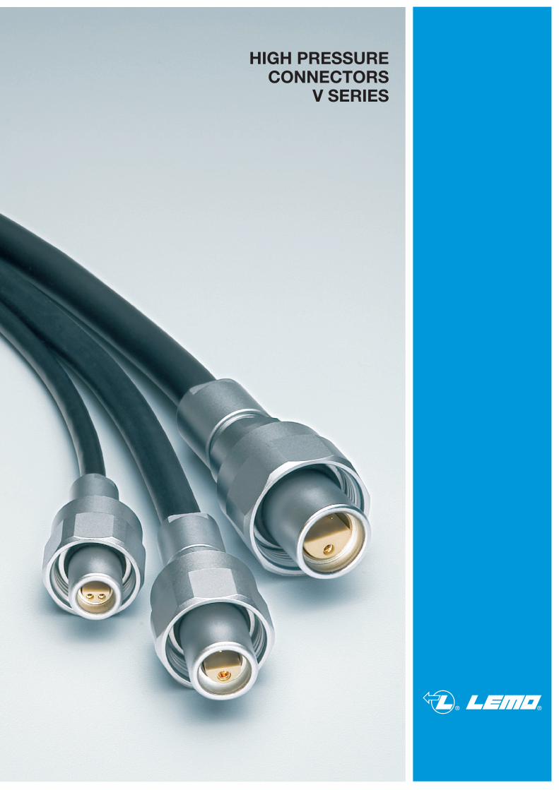
HIGH PRESSURECONNECTORS
V SERIES
® ®
www.lemo.com
Precision modular connectors to suit your applicationSince its creation in Switzerland in 1946 the LEMO Group has been recognized as a global leader of circular Push-Pull connectors and connector solutions. Today LEMO and its affiliated companies, REDEL and COELVER, are active in more than 80 countries with the help of over 40 subsidiaries and distributors.
Over 75000 connectorsThe modular design of the LEMO range provides over 75000 connectors from miniature ø 3 mm to ø 50 mm, capable of handling cable diameters up to 30 mm and for up to 114 contacts.
This vast portfolio enables you to select the ideal connector configuration to suit almost any specific requirement in most markets, including medical devices, test and measurement instruments, machinery, audio video broadcast, telecommuni-cations and military.
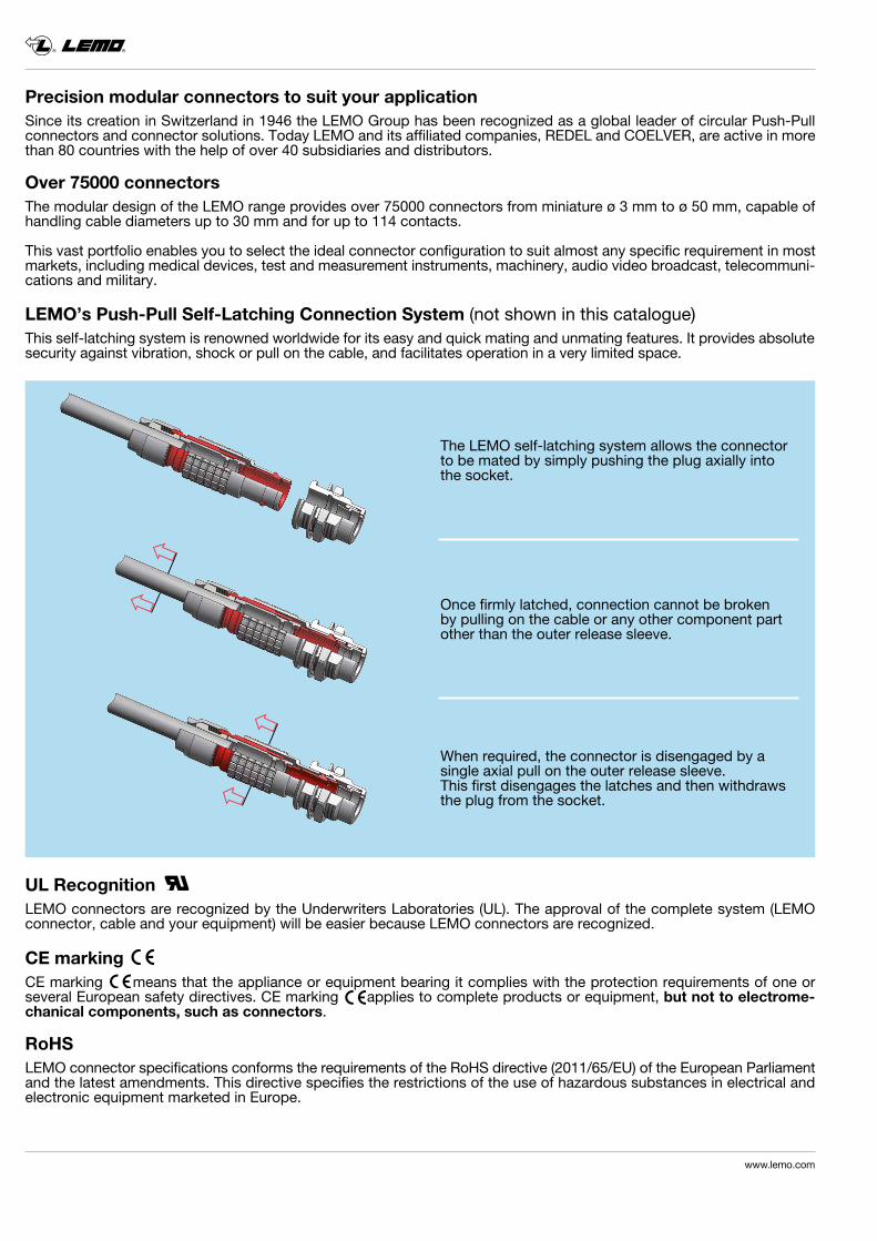
LEMO’s Push-Pull Self-Latching Connection System (not shown in this catalogue)This self-latching system is renowned worldwide for its easy and quick mating and unmating features. It provides absolute security against vibration, shock or pull on the cable, and facilitates operation in a very limited space.
UL RecognitionLEMO connectors are recognized by the Underwriters Laboratories (UL). The approval of the complete system (LEMO connector, cable and your equipment) will be easier because LEMO connectors are recognized.
CE markingCE marking means that the appliance or equipment bearing it complies with the protection requirements of one or several European safety directives. CE marking applies to complete products or equipment, but not to electrome- chanical components, such as connectors.
RoHSLEMO connector specifications conforms the requirements of the RoHS directive (2011/65/EU) of the European Parliament and the latest amendments. This directive specifies the restrictions of the use of hazardous substances in electrical and electronic equipment marketed in Europe.
The LEMO self-latching system allows the connector to be mated by simply pushing the plug axially into the socket.
Once firmly latched, connection cannot be broken by pulling on the cable or any other component part other than the outer release sleeve.
When required, the connector is disengaged by a single axial pull on the outer release sleeve. This first disengages the latches and then withdraws the plug from the socket.
® ®
www.lemo.com 1
V Series
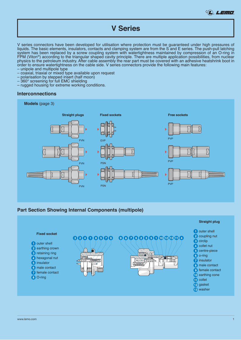
V series connectors have been developed for utilisation where protection must be guaranteed under high pressures of liquids. The basic elements, insulators, contacts and clamping system are from the S and E series. The push-pull latching system has been replaced by a screw coupling system with watertightness maintained by compression of an O-ring in FPM (Viton®) according to the triangular shaped cavity principle. There are multiple application possibilities, from nuclear physics to the petroleum industry. After cable assembly the rear part must be covered with an adhesive heatshrink boot in order to ensure watertightness on the cable side. V series connectors provide the following main features:– unipole and multipole type– coaxial, triaxial or mixed type available upon request– polarisation by stepped insert (half moon)– 360° screening for full EMC shielding– rugged housing for extreme working conditions.
Interconnections
Models (page 3)
Straight plugs Fixed sockets Free sockets
Part Section Showing Internal Components (multipole)
® ®
2 www.lemo.com
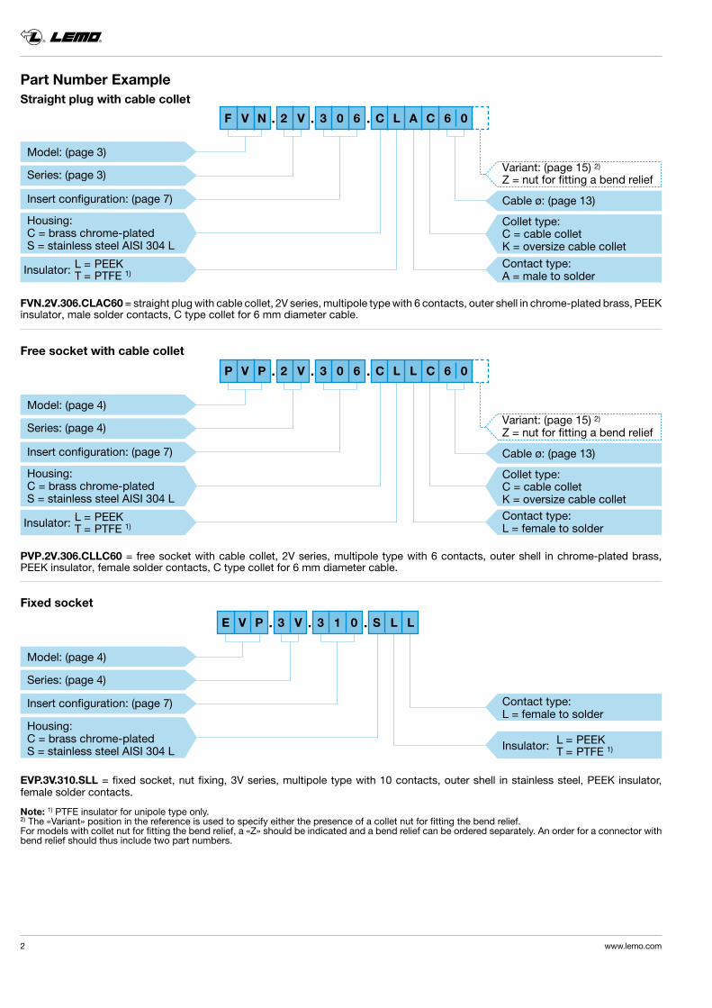
Part Number ExampleStraight plug with cable collet
EVP.3V.310.SLL = fixed socket, nut fixing, 3V series, multipole type with 10 contacts, outer shell in stainless steel, PEEK insulator, female solder contacts.
Note: 1) PTFE insulator for unipole type only.2) The «Variant» position in the reference is used to specify either the presence of a collet nut for fitting the bend relief.For models with collet nut for fitting the bend relief, a «Z» should be indicated and a bend relief can be ordered separately. An order for a connector with bend relief should thus include two part numbers.
FVN.2V.306.CLAC60 = straight plug with cable collet, 2V series, multipole type with 6 contacts, outer shell in chrome-plated brass, PEEK insulator, male solder contacts, C type collet for 6 mm diameter cable.
PVP.2V.306.CLLC60 = free socket with cable collet, 2V series, multipole type with 6 contacts, outer shell in chrome-plated brass, PEEK insulator, female solder contacts, C type collet for 6 mm diameter cable.
Free socket with cable collet
Fixed socket
Contact type: L = female to solder
L = PEEKInsulator: T = PTFE 1)
F V N 2 V 3 0 6 C L A C 6 0
E V P 3 V 3 1 0 S L L
Variant: (page 15) 2)
Z = nut for fitting a bend relief
Cable ø: (page 13)
Collet type:C = cable colletK = oversize cable collet
Contact type: A = male to solder
Model: (page 3)
Series: (page 3)
Insert configuration: (page 7)
Housing:C = brass chrome-platedS = stainless steel AISI 304 L
L = PEEKInsulator: T = PTFE 1)
P V P 2 V 3 0 6 C L L C 6 0
L = PEEKInsulator: T = PTFE 1)
Model: (page 4)
Series: (page 4)
Insert configuration: (page 7)
Housing:C = brass chrome-platedS = stainless steel AISI 304 L
Variant: (page 15) 2)
Z = nut for fitting a bend relief
Cable ø: (page 13)
Collet type:C = cable colletK = oversize cable colletContact type: L = female to solder
Model: (page 4)
Series: (page 4)
Insert configuration: (page 7)
Housing:C = brass chrome-platedS = stainless steel AISI 304 L
.
.
.
.
.
.
.
.
.
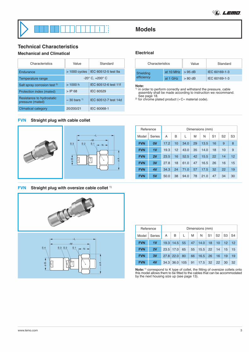
Models
® ®
www.lemo.com 3
Technical CharacteristicsMechanical and Climatical
> 1000 cycles IEC 60512-5 test 9a
-20° C, +200° C
> 1000 h IEC 60512-6 test 11f
> IP 68 IEC 60529
~ 30 bars 1) IEC 60512-7 test 14d
20/200/21 IEC 60068-1
Endurance
Temperature range
Salt spray corrosion test 2)
Protection index (mated)
Resistance to hydrostaticpressure (mated)
Climatical category
Characteristics
StandardValue
Electrical
Note:1) in order to perform correctly and withstand the pressure, cable
assembly shall be made according to instruction we recommand. See page 18.
2) for chrome plated product (« C » material code).
at 10 MHz
at 1 GHz
Characteristics
> 95 dB IEC 60169-1-3
> 80 dB IEC 60169-1-3
Shieldingefficiency
StandardValue
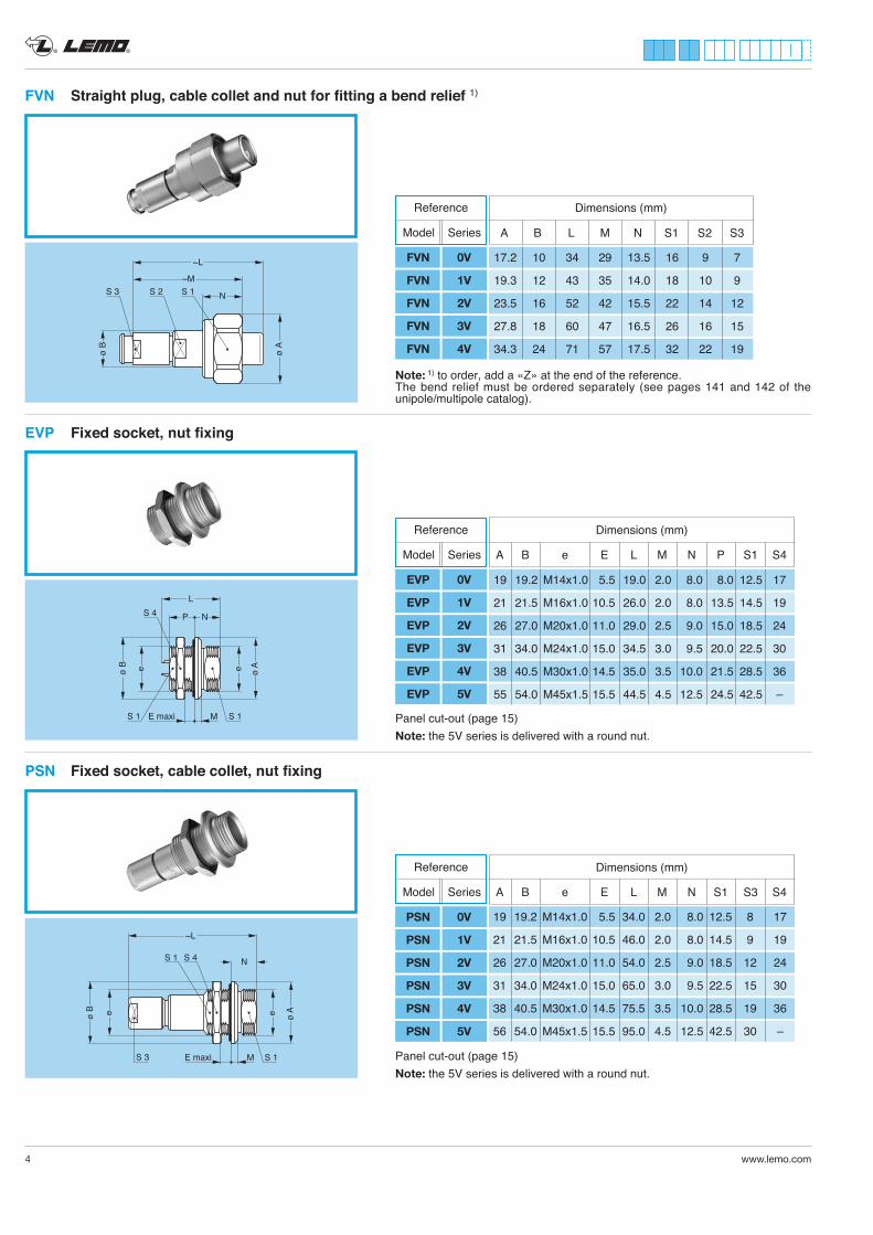
FVN Straight plug with cable collet
FVN Straight plug with oversize cable collet 1)
~M
~L
N
ø A
ø B
S 1S 2S 3
~M
~L
N
ø A
ø B
S 1S 2S 3S 4
Note: 1) correspond to K type of collet, the fitting of oversize collets onto this model allows them to be fitted to the cables that can be accommodated by the next housing size up (see page 13).
17.2 10 34.0 29 13.5 16 9 8
19.3 12 43.0 35 14.0 18 10 9
23.5 16 52.5 42 15.5 22 14 12
27.8 18 61.0 47 16.5 26 16 15
34.3 24 71.0 57 17.5 32 22 19
50.0 38 94.0 78 21.0 47 34 30
Dimensions (mm)
A B L M N S1 S2 S3
19.3 14.5 55 47 14.0 18 10 12 12
23.5 17.0 65 55 15.5 22 14 15 15
27.8 22.0 80 66 16.5 26 16 19 19
34.3 36.0 105 91 17.5 32 22 30 32
Dimensions (mm)
A B L M N S1 S2 S3 S4
Reference
Model Series
FVN 0V
FVN 1V
FVN 2V
FVN 3V
FVN 4V
FVN 5V
Reference
Model Series
FVN 1V
FVN 2V
FVN 3V
FVN 4V
® ®
4 www.lemo.com
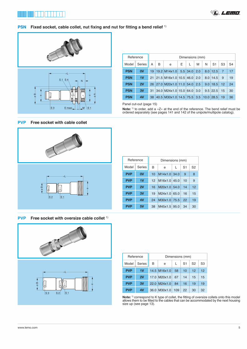
PSN Fixed socket, cable collet, nut fixing
EVP Fixed socket, nut fixing
Panel cut-out (page 15) Note: the 5V series is delivered with a round nut.
Panel cut-out (page 15) Note: the 5V series is delivered with a round nut.
FVN Straight plug, cable collet and nut for fitting a bend relief 1)
Note: 1) to order, add a «Z» at the end of the reference. The bend relief must be ordered separately (see pages 141 and 142 of the unipole/multipole catalog).
17.2 10 34 29 13.5 16 9 7
19.3 12 43 35 14.0 18 10 9
23.5 16 52 42 15.5 22 14 12
27.8 18 60 47 16.5 26 16 15
34.3 24 71 57 17.5 32 22 19
Dimensions (mm)
A B L M N S1 S2 S3
19 19.2 M14x1.0 5.5 19.0 2.0 8.0 8.0 12.5 17
21 21.5 M16x1.0 10.5 26.0 2.0 8.0 13.5 14.5 19
26 27.0 M20x1.0 11.0 29.0 2.5 9.0 15.0 18.5 24
31 34.0 M24x1.0 15.0 34.5 3.0 9.5 20.0 22.5 30
38 40.5 M30x1.0 14.5 35.0 3.5 10.0 21.5 28.5 36
55 54.0 M45x1.5 15.5 44.5 4.5 12.5 24.5 42.5 –
A B e E L M N P S1 S4
Dimensions (mm)
19 19.2 M14x1.0 5.5 34.0 2.0 8.0 12.5 8 17
21 21.5 M16x1.0 10.5 46.0 2.0 8.0 14.5 9 19
26 27.0 M20x1.0 11.0 54.0 2.5 9.0 18.5 12 24
31 34.0 M24x1.0 15.0 65.0 3.0 9.5 22.5 15 30
38 40.5 M30x1.0 14.5 75.5 3.5 10.0 28.5 19 36
56 54.0 M45x1.5 15.5 95.0 4.5 12.5 42.5 30 –
A B e E L M N S1 S3 S4
Dimensions (mm)
Reference
Model Series
FVN 0V
FVN 1V
FVN 2V
FVN 3V
FVN 4V
Reference
Model Series
EVP 0V
EVP 1V
EVP 2V
EVP 3V
EVP 4V
EVP 5V
Reference
Model Series
PSN 0V
PSN 1V
PSN 2V
PSN 3V
PSN 4V
PSN 5V
® ®
www.lemo.com 5
PVP Free socket with oversize cable collet 1)
PVP Free socket with cable collet
Note: 1) correspond to K type of collet, the fitting of oversize collets onto this model allows them to be fitted to the cables that can be accommodated by the next housing size up (see page 13).
PSN Fixed socket, cable collet, nut fixing and nut for fitting a bend relief 1)
Panel cut-out (page 15) Note: 1) to order, add a «Z» at the end of the reference. The bend relief must be ordered separately (see pages 141 and 142 of the unipole/multipole catalog).
14.5 M16x1.0 58 10 12 12
17.0 M20x1.0 67 14 15 15
22.0 M24x1.0 84 16 19 19
36.0 M30x1.0 109 22 30 32
B e L S1 S2 S3
Dimensions (mm)
B e L S1 S2
Dimensions (mm)
10 M14x1.0 34.0 9 8
12 M16x1.0 45.0 10 9
16 M20x1.0 54.0 14 12
19 M24x1.0 65.0 16 15
24 M30x1.0 75.5 22 19
38 M45x1.5 95.0 34 30
19 19.2 M14x1.0 5.5 34.0 2.0 8.0 12.5 7 17
21 21.5 M16x1.0 10.5 46.0 2.0 8.0 14.5 9 19
26 27.0 M20x1.0 11.0 54.0 2.5 9.0 18.5 12 24
31 34.0 M24x1.0 15.0 64.0 3.0 9.5 22.5 15 30
38 40.5 M30x1.0 14.5 75.5 3.5 10.0 28.5 19 36
A B e E L M N S1 S3 S4
Dimensions (mm)Reference
Model Series
PSN 0V
PSN 1V
PSN 2V
PSN 3V
PSN 4V
Reference
Model Series
PVP 0V
PVP 1V
PVP 2V
PVP 3V
PVP 4V
PVP 5V
Reference
Model Series
PVP 1V
PVP 2V
PVP 3V
PVP 4V
® ®
6 www.lemo.com
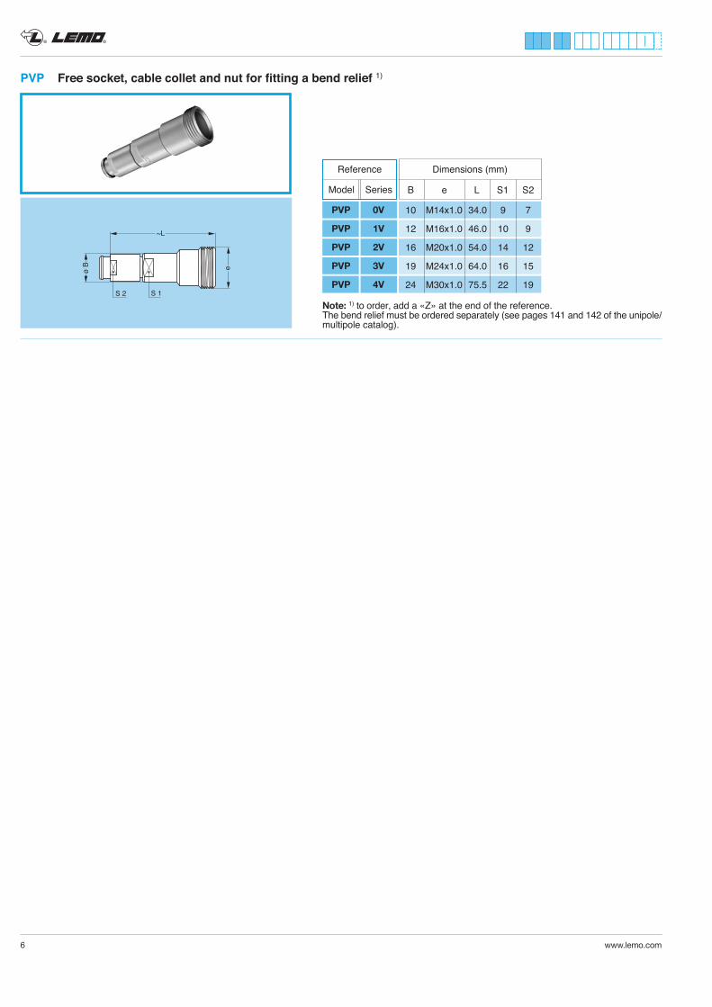
PVP Free socket, cable collet and nut for fitting a bend relief 1)
Note: 1) to order, add a «Z» at the end of the reference.The bend relief must be ordered separately (see pages 141 and 142 of the unipole/multipole catalog).
10 M14x1.0 34.0 9 7
12 M16x1.0 46.0 10 9
16 M20x1.0 54.0 14 12
19 M24x1.0 64.0 16 15
24 M30x1.0 75.5 22 19
Dimensions (mm)
B e L S1 S2
Reference
Model Series
PVP 0V
PVP 1V
PVP 2V
PVP 3V
PVP 4V
® ®
www.lemo.com 7
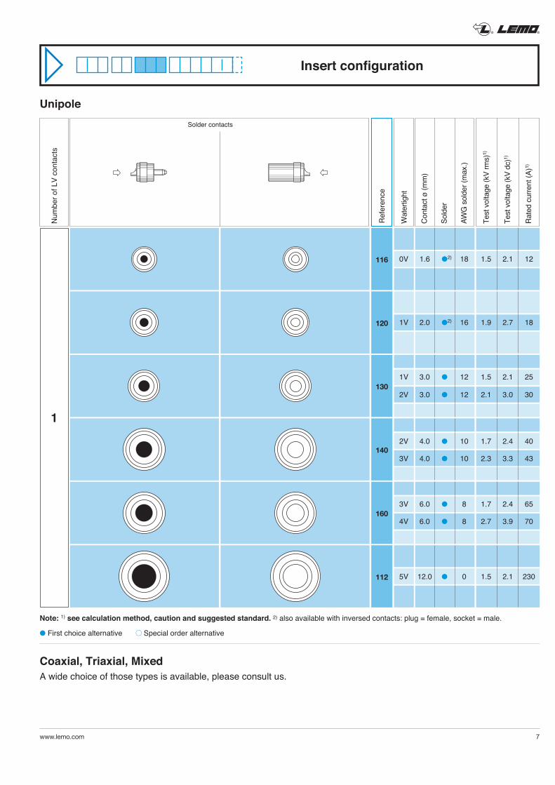
Insert configuration
Solder contacts
Note: 1) see calculation method, caution and suggested standard. 2) also available with inversed contacts: plug = female, socket = male.
l First choice alternative Special order alternative
Unipole
Coaxial, Triaxial, Mixed A wide choice of those types is available, please consult us.
116
120
130
140
160
112
Ref
eren
ce
Num
ber o
f LV
cont
acts
Cont
act ø
(mm
)
Sold
er
AWG
sol
der (
max
.)
Test
vol
tage
(kV
rms)
1)
Test
vol
tage
(kV
dc)1)
Rate
d cu
rrent
(A)1)
1W
ater
tight
0V 1.6 l2) 18 1.5 2.1 12
1V 2.0 l2) 16 1.9 2.7 18
1V 3.0 l 12 1.5 2.1 25
2V 3.0 l 12 2.1 3.0 30
2V 4.0 l 10 1.7 2.4 40
3V 4.0 l 10 2.3 3.3 43
3V 6.0 l 8 1.7 2.4 65
4V 6.0 l 8 2.7 3.9 70
5V 12.0 l 0 1.5 2.1 230
2
1
1
3
2
1 2
4 3
5
2
1
3
4
2
1
2
3
1
2 1
3 4
4
23
1
5
2
3
4
5
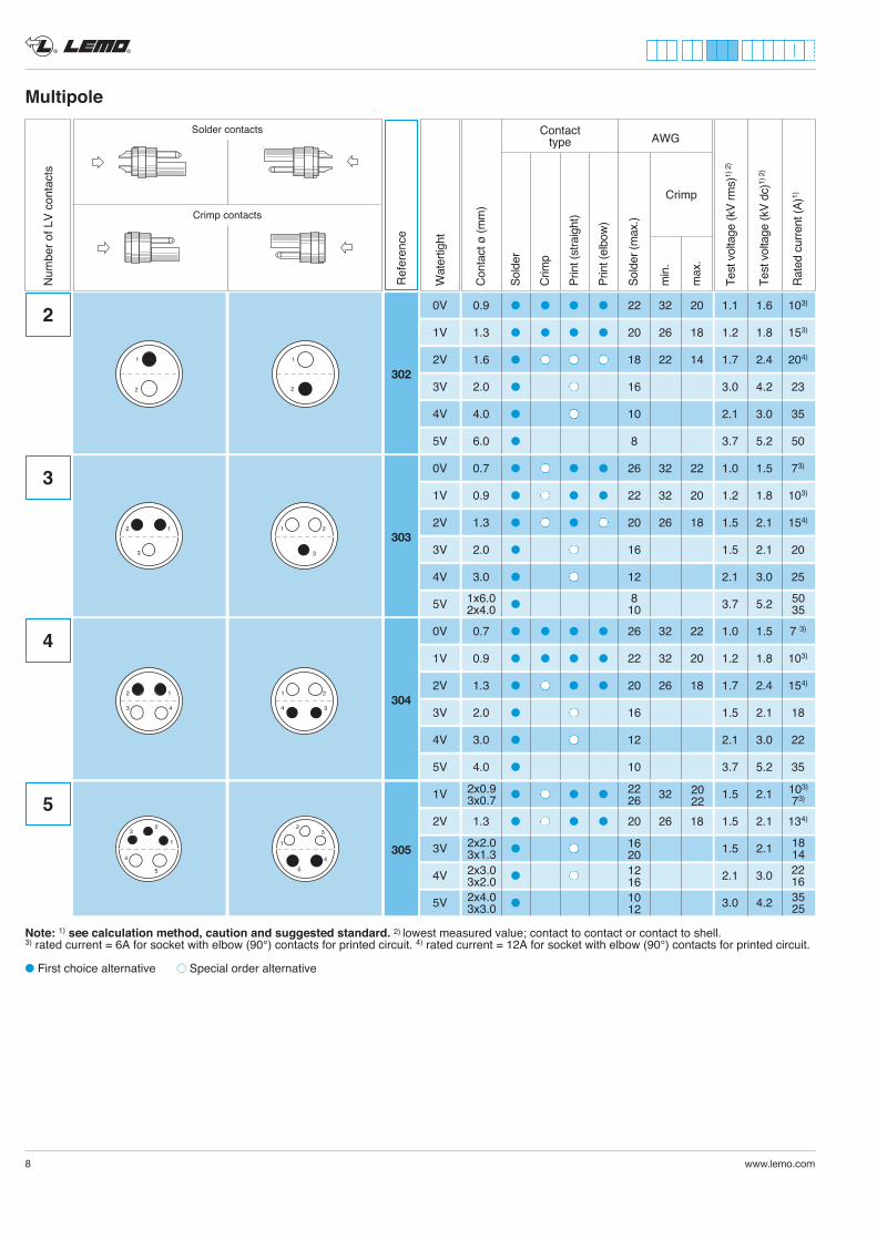
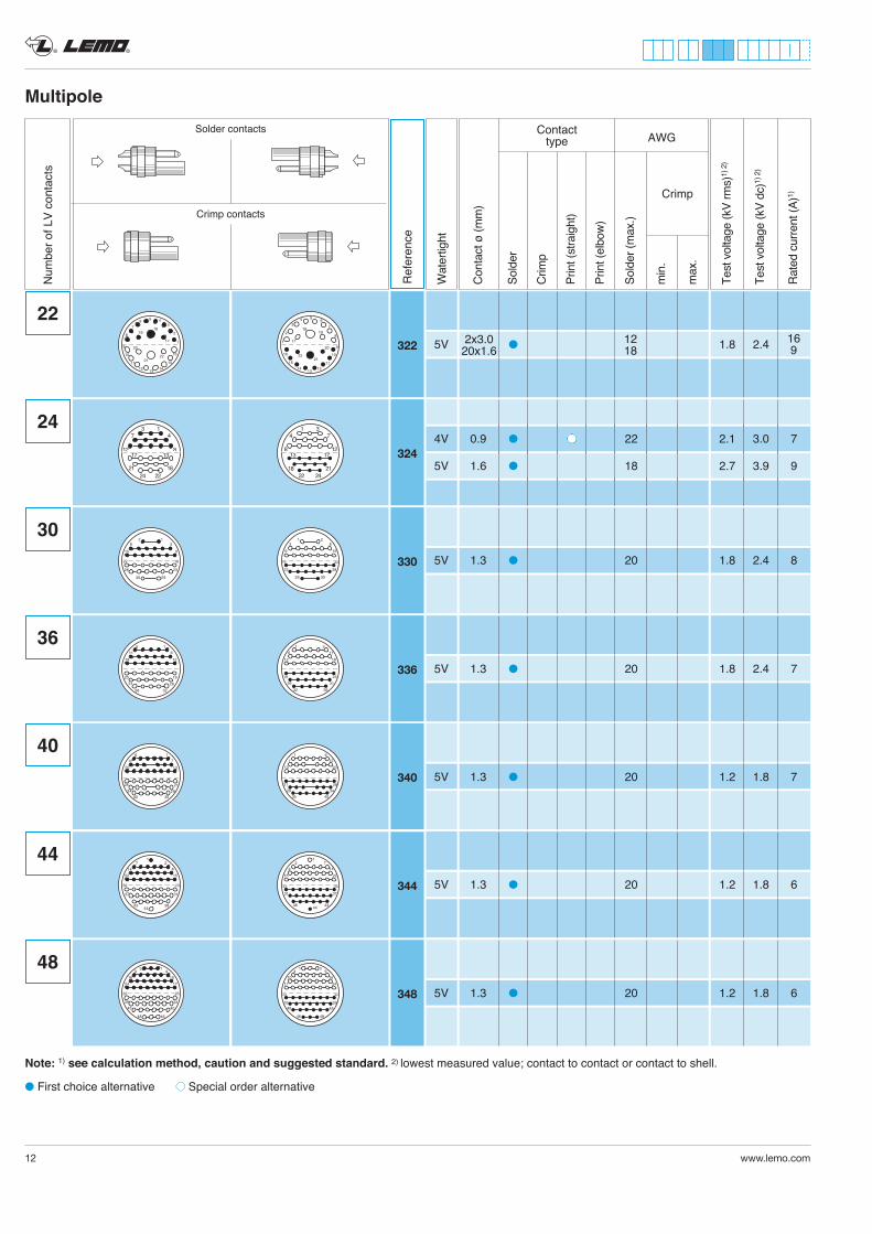
Multipole
Num
ber o
f LV
cont
acts
Cont
act ø
(mm
)
Sold
er
Crim
p
Prin
t (st
raig
ht)
Prin
t (el
bow)
Sold
er (m
ax.)
min
.
max
.
AWG
Crimp
Test
vol
tage
(kV
rms)
1) 2
)
Test
vol
tage
(kV
dc)1)
2)
Rate
d cu
rrent
(A)1)
Contacttype
Solder contacts
Crimp contacts
Note: 1) see calculation method, caution and suggested standard. 2) lowest measured value; contact to contact or contact to shell.3) rated current = 6A for socket with elbow (90°) contacts for printed circuit. 4) rated current = 12A for socket with elbow (90°) contacts for printed circuit.
l First choice alternative Special order alternative
103) 73)
22 16
18 14
35 25
302
Ref
eren
ce
303
304
305
Wat
ertig
ht
® ®
8 www.lemo.com
20 22
8 10
1x6.0 2x4.0
50 35
2x0.9 3x0.7
2x2.0 3x1.32x3.0 3x2.02x4.0 3x3.0
22 26
16 2012 1610 12
0V 0.9 l l l l 22 32 20 1.1 1.6 103)
1V 1.3 l l l l 20 26 18 1.2 1.8 153)
2V 1.6 l l l l 18 22 14 1.7 2.4 204)
3V 2.0 l l 16 3.0 4.2 23
4V 4.0 l l 10 2.1 3.0 35
5V 6.0 l 8 3.7 5.2 50
0V 0.7 l l l l 26 32 22 1.0 1.5 73)
1V 0.9 l l l l 22 32 20 1.2 1.8 103)
2V 1.3 l l l l 20 26 18 1.5 2.1 154)
3V 2.0 l l 16 1.5 2.1 20
4V 3.0 l l 12 2.1 3.0 25
5V l 3.7 5.2
0V 0.7 l l l l 26 32 22 1.0 1.5 7 3)
1V 0.9 l l l l 22 32 20 1.2 1.8 103)
2V 1.3 l l l l 20 26 18 1.7 2.4 154)
3V 2.0 l l 16 1.5 2.1 18
4V 3.0 l l 12 2.1 3.0 22
5V 4.0 l 10 3.7 5.2 35
1V l l l l 32 1.5 2.1
2V 1.3 l l l l 20 26 18 1.5 2.1 134)
3V l l 1.5 2.1
4V l l 2.1 3.0
5V l 3.0 4.2
® ®
www.lemo.com 9
65
4
2
1
3
4
56
23
1
6
306
3071
32
4
76
5
42
3
1
5
67
7
1
32
4
87 6
5
4
23
1
5
6 7
8
8
308
3099
8
6
7
1
42
5
3
6
79
8
5 24
1
39
101 9
3
6
2
7
4
510
8
4
9
2
7
3
6
1
8
105 310
310
101
42
79
5
10
8
3
6
5 24
97
16
8
3
10
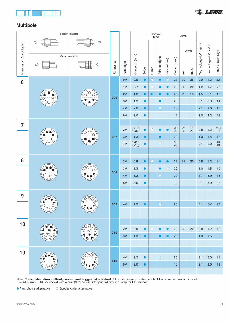
Multipole
Ref
eren
ce
Num
ber o
f LV
cont
acts
Cont
act ø
(mm
)
Sold
er
Crim
p
Prin
t (st
raig
ht)
Prin
t (el
bow)
Sold
er (m
ax.)
min
.
max
.
AWG
Crimp
Test
vol
tage
(kV
rms)
1) 2
)
Test
vol
tage
(kV
dc)1)
2)
Rate
d cu
rrent
(A)1)
Contacttype
Solder contacts
Crimp contacts
Note: 1) see calculation method, caution and suggested standard. 2) lowest measured value; contact to contact or contact to shell.3) rated current = 6A for socket with elbow (90°) contacts for printed circuit. 4) only for FFL model.
l First choice alternative Special order alternative
123) 93)
1613
Wat
ertig
ht
0V 0.5 l l l l 28 32 28 0.9 1.3 2.5
1V 0.7 l l l l 26 32 22 1.2 1.7 73)
2V 1.3 l l4) l l 20 26 18 1.5 2.1 12
3V 1.3 l l 20 2.1 3.0 14
4V 2.0 l l 16 2.1 3.0 16
5V 3.0 l 12 3.0 4.2 25
2V l l l l 0.8 1.2
3V 1.3 l l 20 1.0 1.5 12
4V l l 2.1 3.0
2V 0.9 l l l l 22 32 20 0.8 1.2 93)
3V 1.3 l l l 20 1.0 1.5 10
4V 1.3 l l 20 2.7 3.9 13
5V 3.0 l 12 2.1 3.0 22
4V 1.3 l l 20 2.1 3.0 12
2V 0.9 l l l l 22 32 20 0.8 1.2 73)
3V 1.3 l l l 20 1.0 1.5 9
4V 1.3 l l 20 2.1 3.0 11
5V 2.0 l 16 2.1 3.0 18
20 22
26 32
18 20
3x1.3 4x0.9
16 20
3x2.0 4x1.3
® ®
10 www.lemo.com
123
2
12
1
11
6107
6
1
11
2
12
3710 312
1
42
79
5
11
10
12
8
3
6
5 24
97
1116 12
8
3
10
6
1
12
5
2
11
43
109
8
7
1
6
7
2
5
8
34
910
11
12
4
3
13
1
12
7118
7
1
12
3
13
4811
12
12
13
312
312
313
3144
3
14
1
12
7118
7
1
12
3
14
4811
1
42
79
512
13
11
14
10
8
3
6
52
4
97
111
14
12
136
8
3
10
14
14314
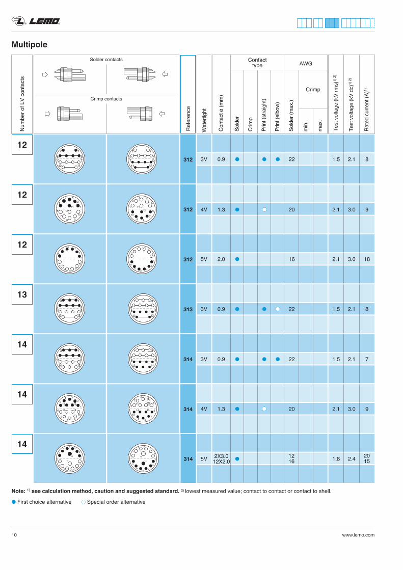
Multipole
Ref
eren
ce
Num
ber o
f LV
cont
acts
Cont
act ø
(mm
)
Sold
er
Crim
p
Prin
t (st
raig
ht)
Prin
t (el
bow)
Sold
er (m
ax.)
min
.
max
.
AWG
Crimp
Test
vol
tage
(kV
rms)
1) 2
)
Test
vol
tage
(kV
dc)1)
2)
Rate
d cu
rrent
(A)1)
Contacttype
Solder contacts
Crimp contacts
Note: 1) see calculation method, caution and suggested standard. 2) lowest measured value; contact to contact or contact to shell.
l First choice alternative Special order alternative
Wat
ertig
ht
3146
1
12
5
2
11
43
109
8
7
13
14
1
6
7
2
5
8
34
910
11
12
13
14
14
20 15
3V 0.9 l l l 22 1.5 2.1 8
4V 1.3 l l 20 2.1 3.0 9
5V 2.0 l 16 2.1 3.0 18
3V 0.9 l l l 22 1.5 2.1 8
3V 0.9 l l l 22 1.5 2.1 7
4V 1.3 l l 20 2.1 3.0 9
5V l 1.8 2.412 16
2X3.0 12X2.0
® ®
www.lemo.com 11
Multipole
41
85129
1613
14
58912
1316
6
1
12
52
11
43
109
8
7
14
13
15
16
1
6
7
2
5
8
34
910
11
12
13
14
16
15
16
16
316
316
18
18
1410
1815
41
951014
1518
14
59
817
3
2
7
4 6
16
15
14 12
11
9
1018
13
5
1117
67
2
5
3
9
10
11
1314
16
15
18
12
4
8
318
318
Ref
eren
ce
Num
ber o
f LV
cont
acts
Cont
act ø
(mm
)
Sold
er
Crim
p
Prin
t (st
raig
ht)
Prin
t (el
bow)
Sold
er (m
ax.)
min
.
max
.
AWG
Crimp
Test
vol
tage
(kV
rms)
1) 2
)
Test
vol
tage
(kV
dc)1)
2)
Rate
d cu
rrent
(A)1)
Contacttype
Solder contacts
Crimp contacts
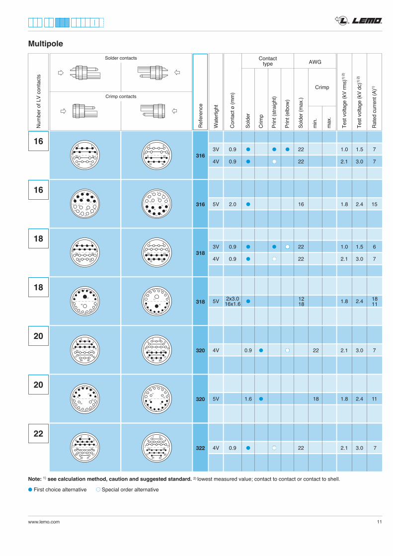
Note: 1) see calculation method, caution and suggested standard. 2) lowest measured value; contact to contact or contact to shell.
l First choice alternative Special order alternative
1811
Wat
ertig
ht
6
31
2018
10
4 5
11 15
16 17
10
13
1820
6
5 4
15 11
17 16
8
18
17
19
20
3
27
4 6
16
15
14 12
11
9
10
13
5
11
17
18
20
19
6
7
2
5
3
9
10
11
13 14
16
15
12
4
8
20320
20 320
36
20
11
17
16
12
12
22
7
21
22 322
63
17
7
20
12
21
16
21
11
22
3V 0.9 l l l 22 1.0 1.5 7
4V 0.9 l l 22 2.1 3.0 7
5V 2.0 l 16 1.8 2.4 15
3V 0.9 l l l 22 1.0 1.5 6
4V 0.9 l l 22 2.1 3.0 7
5V l 1.8 2.4
4V 0.9 l l 22 2.1 3.0 7
5V 1.6 l 18 1.8 2.4 11
4V 0.9 l l 22 2.1 3.0 7
12 18
2x3.0 16x1.6
Multipole
Ref
eren
ce
Num
ber o
f LV
cont
acts
Cont
act ø
(mm
)
Sold
er
Crim
p
Prin
t (st
raig
ht)
Prin
t (el
bow)
Sold
er (m
ax.)
min
.
max
.
AWG
Crimp
Test
vol
tage
(kV
rms)
1) 2
)
Test
vol
tage
(kV
dc)1)
2)
Rate
d cu
rrent
(A)1)
Contacttype
Solder contacts
Crimp contacts
Note: 1) see calculation method, caution and suggested standard. 2) lowest measured value; contact to contact or contact to shell.
l First choice alternative Special order alternative
Wat
ertig
ht
® ®
12 www.lemo.com
12
13
2224
8
7 4
17 13
21 18
117
18
20
2122
19
6
7
2
5
3
9
10
11
1314
16
15
12
4
8
22
24
322
324
169
22
2328
2930
2 13
9 15
16
8
30 330
33625 19
26
36
31
32
5 1
11 6
18 12
36
28 21
34 29
40 35
6 1
12 7
1320
40340
8
31
2422
12
4 7
13 17
18 21
819
18
2221
20
17
3
2
7
4 6
16
15
14 1211
9
10
13
5
1
16
2823
3029
1 28
15 9
22
3
19 25
31
32
26
36
1 5
6 11
12 18
21 28
29 34
35 40
1 6
7 12
2013
3731
433844
172
148
2215
3023
3137
384344
127
814
1522
2330
44344
34825 32
33 3940 45
46 48
4 91 3
10 16
2417
32 25
39 33
45 40
48 46
9 43 1
16 10
1724
48
5V l 1.8 2.4
4V 0.9 l l 22 2.1 3.0 7
5V 1.6 l 18 2.7 3.9 9
5V 1.3 l 20 1.8 2.4 8
5V 1.3 l 20 1.8 2.4 7
5V 1.3 l 20 1.2 1.8 7
5V 1.3 l 20 1.2 1.8 6
5V 1.3 l 20 1.2 1.8 6
12 18
2x3.0 20x1.6
® ®
www.lemo.com 13
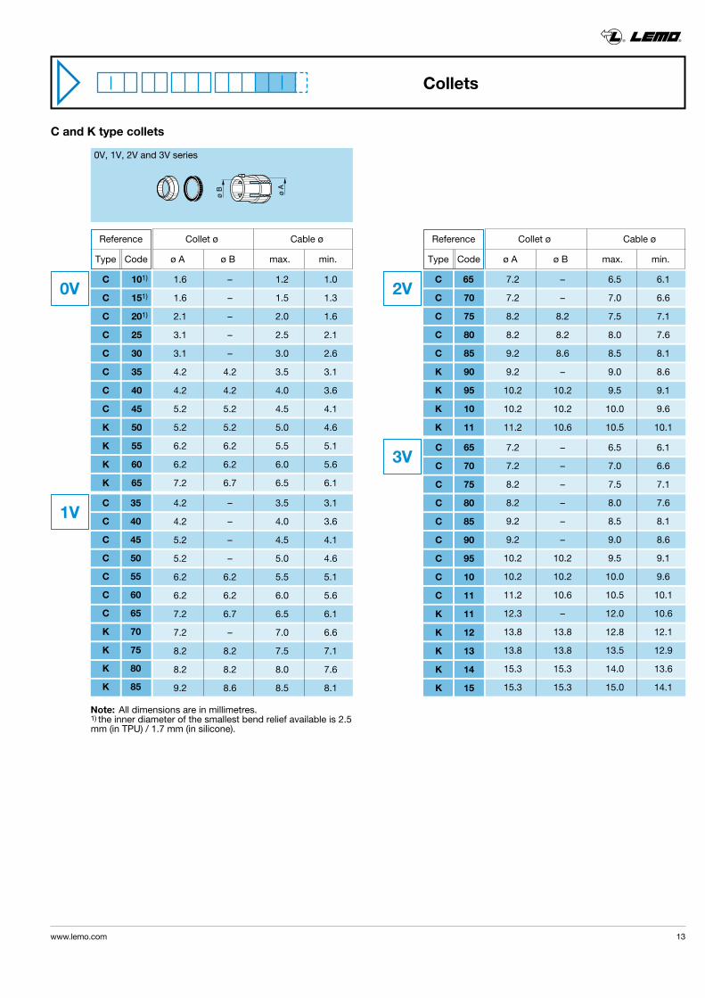
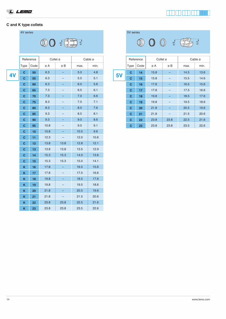
C and K type collets
ø B ø A
0V, 1V, 2V and 3V series
4.2 – 3.5 3.1
4.2 – 4.0 3.6
5.2 – 4.5 4.1
5.2 – 5.0 4.6
6.2 6.2 5.5 5.1
6.2 6.2 6.0 5.6
7.2 6.7 6.5 6.1
7.2 – 7.0 6.6
8.2 8.2 7.5 7.1
8.2 8.2 8.0 7.6
9.2 8.6 8.5 8.1
7.2 – 6.5 6.1
7.2 – 7.0 6.6
8.2 8.2 7.5 7.1
8.2 8.2 8.0 7.6
9.2 8.6 8.5 8.1
9.2 – 9.0 8.6
10.2 10.2 9.5 9.1
10.2 10.2 10.0 9.6
11.2 10.6 10.5 10.1
7.2 – 6.5 6.1
7.2 – 7.0 6.6
8.2 – 7.5 7.1
8.2 – 8.0 7.6
9.2 – 8.5 8.1
9.2 – 9.0 8.6
10.2 10.2 9.5 9.1
10.2 10.2 10.0 9.6
11.2 10.6 10.5 10.1
12.3 – 12.0 10.6
13.8 13.8 12.8 12.1
13.8 13.8 13.5 12.9
15.3 15.3 14.0 13.6
15.3 15.3 15.0 14.1
1V
2V
3V
Reference
Type Code
Reference
Type Code
Collet ø Cable ø ø A ø B max. min.
Collet ø Cable ø ø A ø B max. min.
C 35
C 40
C 45
C 50
C 55
C 60
C 65
K 70
K 75
K 80
K 85
C 65
C 70
C 75
C 80
C 85
K 90
K 95
K 10
K 11
C 65
C 70
C 75
C 80
C 85
C 90
C 95
C 10
C 11
K 11
K 12
K 13
K 14
K 15
Note: All dimensions are in millimetres.1) the inner diameter of the smallest bend relief available is 2.5 mm (in TPU) / 1.7 mm (in silicone).
Collets
1.6 – 1.2 1.0
1.6 – 1.5 1.3
2.1 – 2.0 1.6
3.1 – 2.5 2.1
3.1 – 3.0 2.6
4.2 4.2 3.5 3.1
4.2 4.2 4.0 3.6
5.2 5.2 4.5 4.1
5.2 5.2 5.0 4.6
6.2 6.2 5.5 5.1
6.2 6.2 6.0 5.6
7.2 6.7 6.5 6.1
0V C 101)
C 151)
C 201)
C 25
C 30
C 35
C 40
C 45
K 50
K 55
K 60
K 65
® ®
14 www.lemo.com
4V 6.3 – 5.0 4.8
6.3 – 5.5 5.1
6.3 – 6.0 5.6
7.3 – 6.5 6.1
7.3 – 7.0 6.6
8.3 – 7.5 7.1
8.3 – 8.0 7.6
9.3 – 8.5 8.1
9.3 – 9.0 8.6
10.8 – 9.5 9.1
10.8 – 10.5 9.6
12.3 – 12.0 10.6
13.8 13.8 12.8 12.1
13.8 13.8 13.5 12.9
15.3 15.3 14.0 13.6
15.3 15.3 15.0 14.1
17.8 – 16.5 15.6
17.8 – 17.5 16.6
19.8 – 18.5 17.6
19.8 – 19.5 18.6
21.8 – 20.5 19.6
21.8 – 21.5 20.6
23.8 23.8 22.5 21.6
23.8 23.8 23.5 22.6
C 50
C 55
C 60
C 65
C 70
C 75
C 80
C 85
C 90
C 95
C 10
C 11
C 12
C 13
C 14
C 15
K 16
K 17
K 18
K 19
K 20
K 21
K 22
K 23
Reference
Type Code
Collet ø Cable ø ø A ø B max. min.
C and K type collets
ø B ø A
Reference
Type Code
Collet ø Cable ø ø A ø B max. min.
C 14
C 15
C 16
C 17
C 18
C 19
C 20
C 21
C 22
C 23
15.8 – 14.5 13.6
15.8 – 15.5 14.6
17.8 – 16.5 15.6
17.8 – 17.5 16.6
19.8 – 18.5 17.6
19.8 – 19.5 18.6
21.8 – 20.5 19.6
21.8 – 21.5 20.6
23.8 23.8 22.5 21.6
23.8 23.8 23.5 22.6
5V
5V series
ø B ø A
4V series
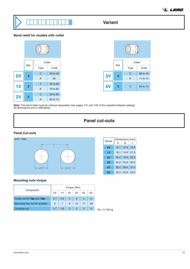
Variant
® ®
www.lemo.com 15
Panel cut-outs
Note: The bend relief must be ordered separately (see pages 141 and 142 of the unipole/multipole catalog).All dimensions are in millimetres.
Bend relief for models with collet
Panel Cut-outs
Mounting nuts torque
L
ø A +0.1 0ø B +0.1
0
EVP, PSN Dimensions (mm) A B L 14.1 12.6 19.0
16.1 14.6 21.0
20.2 18.6 25.5
24.2 22.6 30.0
30.2 28.6 37.0
45.2 42.6 53.0
Series
0V
1V
2V
3V
4V
5V
Component
0.7 0.8 2 3 5 8
5 7 9 12 17 22
0.7 0.8 2 3 5 8
Torque (Nm)
0V 1V 2V 3V 4V 5V
Collet nut for Fll and Pll
Mounting hex nut for sockets
Coupling nut 1N = 0.102 kg
0V Z
Ref.Collet
Type Code
2V Z C 65 to 85
K 90 to 10
1V Z C 35 to 65
K 70 to 85
C 35 to 45
K 50
Ref.Collet
Type Code
4V Z C 65 to 15
3V Z C 65 to 10
K 11 to 15
Accessories
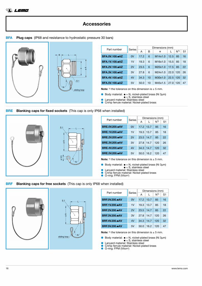
BFA Plug caps (IP68 and resistance to hydrostatic pressure 30 bars)
LS 1
ø A
N
ø 3.
5
sliding loop
LS 1
ø A
N
LB
e ø A
N
S 1
sliding loop
BRF Blanking caps for free sockets (This cap is only IP68 when installed)
BRE Blanking caps for fixed sockets (This cap is only IP68 when installed)
l Body material: l = N, nickel-plated brass (Ni 3µm) l = S, stainless steell Lanyard material: Stainless steell Crimp ferrule material: Nickel-plated brassl O-ring: FPM (Viton®)
® ®
16 www.lemo.com
Part number Series
BRF.0V.200.lAV
BRF.1V.200.lAV
BRF.2V.200.lAV
BRF.3V.200.lAV
BRF.4V.200.lAV
BRF.5V.200.lAV
0V 17.2 13.7 85 16
1V 19.3 13.7 85 18
2V 23.5 14.7 85 22
3V 27.8 14.7 120 26
4V 34.3 14.7 120 32
5V 50.0 16.2 120 47
Series
BFA.0V.100.lAZ
BFA.1V.100.lAZ
BFA.2V.100.lAZ
BFA.3V.100.lAZ
BFA.4V.100.lAZ
BFA.5V.100.lAZ
0V 17.2 6 M14x1.0 12.5 85 16
1V 19.3 6 M16x1.0 15.5 85 18
2V 23.5 6 M20x1.0 17.5 85 22
3V 27.8 6 M24x1.0 22.0 120 26
4V 34.3 10 M30x1.0 22.5 120 32
5V 50.0 10 M45x1.5 27.0 120 47
Part number Dimensions (mm) A B e L N1) S1
Part number Series
BRE.0V.200.lAV
BRE.1V.200.lAV
BRE.2V.200.lAV
BRE.3V.200.lAV
BRE.4V.200.lAV
BRE.5V.200.lAV
0V 17.2 13.7 85 16
1V 19.3 13.7 85 18
2V 23.5 14.7 85 22
3V 27.8 14.7 120 26
4V 34.3 14.7 120 32
5V 50.0 16.2 120 47
Dimensions (mm) A L N1) S1
Dimensions (mm) A L N1) S1
Note: 1) the tolerance on this dimension is ± 5 mm.
l Body material: l = N, nickel-plated brass (Ni 3µm) l = S, stainless steell Lanyard material: Stainless steell Crimp ferrule material: Nickel-plated brassl O-ring: FPM (Viton®)
Note: 1) the tolerance on this dimension is ± 5 mm.
l Body material: l = N, nickel-plated brass (Ni 3µm) l = S, stainless steell Lanyard material: Stainless steell Crimp ferrule material: Nickel-plated brass
Note: 1) the tolerance on this dimension is ± 5 mm.
® ®
www.lemo.com 17
GEA Hexagonal nuts
e L
ø A
ø A
ø C
e L
A
øB
GDA O-ring for plug
GEB Round nuts
Note: to order this part separately, use the above part numbers. The last letters «LN» of the part number refer to the nut material and treatment. If a nut in stainless steel is desired, replace the last letters of the part number by «AZ».l Material:
– Nickel-plated brass (3 µm)– Stainless steel
Note: to order this part separately, use the above part numbers. The last letters «LN» of the part number refer to the nut material and treatment. If a nut in stainless steel is desired, replace the last letters of the part number by «AZ».
l Material: FPM (Viton®)
l Material:– Nickel-plated brass (3 µm)– Stainless steel
Part number Series
GEA.0E.240.LN
GEA.1E.240.LN
GEA.2E.240.LN
GEA.3E.240.LN
GEA.4E.240.LN
0V 17 19.2 M14 x 1.00 2.5
1V 19 21.5 M16 x 1.00 3.0
2V 24 27.0 M20 x 1.00 4.0
3V 30 34.0 M24 x 1.00 5.0
4V 36 40.5 M30 x 1.00 7.0
Part number Dim. (mm) A CSeries
GDA.99.080.100VK
GDA.99.100.100VK
GDA.99.130.150VK
GDA.99.165.150VK
GDA.99.210.200VK
GDA.99.330.250VK
0V 8.0 1.0
1V 10.0 1.0
2V 13.0 1.5
3V 16.5 1.5
4V 21.0 2.0
5V 33.0 2.5
Dimensions (mm) A B e L
Part number Series
GEB.5E.240.LN 5V 54 M45 X 1.5 8.0
Dimensions (mm) A e L
® ®
18 www.lemo.com
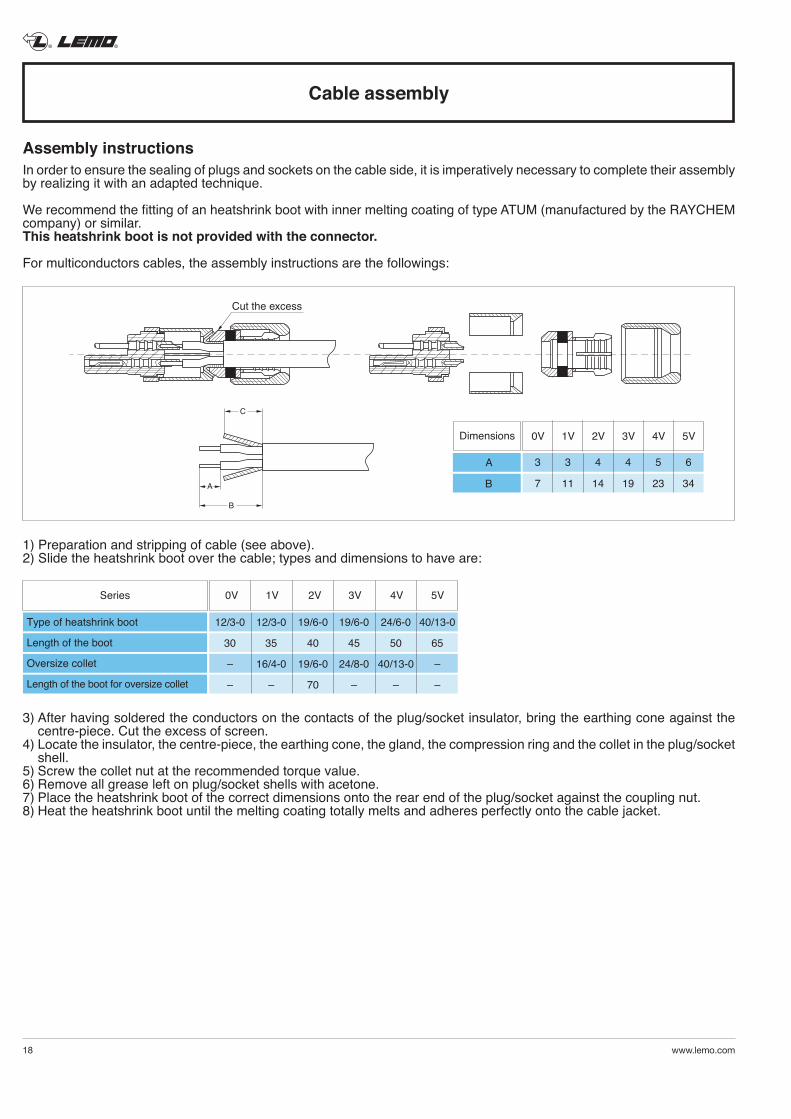
1) Preparation and stripping of cable (see above).2) Slide the heatshrink boot over the cable; types and dimensions to have are:
3) After having soldered the conductors on the contacts of the plug/socket insulator, bring the earthing cone against the centre-piece. Cut the excess of screen.
4) Locate the insulator, the centre-piece, the earthing cone, the gland, the compression ring and the collet in the plug/socket shell.
5) Screw the collet nut at the recommended torque value.6) Remove all grease left on plug/socket shells with acetone.7) Place the heatshrink boot of the correct dimensions onto the rear end of the plug/socket against the coupling nut.8) Heat the heatshrink boot until the melting coating totally melts and adheres perfectly onto the cable jacket.
Cable assembly
Assembly instructionsIn order to ensure the sealing of plugs and sockets on the cable side, it is imperatively necessary to complete their assembly by realizing it with an adapted technique.
We recommend the fitting of an heatshrink boot with inner melting coating of type ATUM (manufactured by the RAYCHEM company) or similar.This heatshrink boot is not provided with the connector.
For multiconductors cables, the assembly instructions are the followings:
A
B
C
Cut the excess
Dimensions 0V 1V 2V 3V 4V 5V
3 3 4 4 5 6
7 11 14 19 23 34
A
B
Series 0V 1V 2V 3V 4V 5V
12/3-0 12/3-0 19/6-0 19/6-0 24/6-0 40/13-0
30 35 40 45 50 65
– 16/4-0 19/6-0 24/8-0 40/13-0 –
– – 70 – – –
Type of heatshrink boot
Length of the boot
Oversize collet
Length of the boot for oversize collet
® ®
www.lemo.com 19
LEMO works constantly to improve the quality of its products; the information and illustrations figuring in this document may therefore vary and are not binding. In any case, LEMO makes no specific warranty of merchantability, fitness for a particu-lar purpose, third party components as such or included in assembly, non-infringement, title, accuracy, completeness, or security. The user is fully responsible for his products and applications using LEMO component. In no event shall LEMO, its affiliates, officers, agents or employees be liable for any incidental, indirect, special or consequen-tial damages in connection with the products or services provided by LEMO, including (without limitation) loss of profits or revenues, interruption of business, loss of use of the products or any associated equipment, materials, components or products, damages to associated equipment or in combination with other components, materials. Reproduction of significant portions of LEMO information in LEMO data books or data sheets is permissible only if repro-duction is without alteration and is accompanied by all associated warranties, conditions, limitations, and notices. LEMO is not responsible or liable for such altered documentation. Information of third parties may be subject to additional restrictions.
Disclaimers
No reproduction or use without express permission of editorial or pictorial content, in any manner.LEMO SA reserves the right to modify and improve specifications, at all times, without any notification.
PLEASE READ AND FOLLOW ALL INSTUCTIONS CAREFULLY AND CONSULT ALL RELEVENT NATIONAL AND INTERNATIONAL SAFETY REGULATIONS FOR YOUR APPLICATION.IMPROPER HANDLING, CABLE ASSEMBLY, OR WRONG USE OF CONNECTORS CAN RESULT IN HAZARDOUS SITUATIONS.
1. SHOCK AND FIRE HAZARDIncorrect wiring, the use of damaged components, presence of foreign objects (such as metal debris), and / or residue (such as cleaning fluids), can result in short circuits, overheating, and / or risk of electric shock.Mated components should never be disconnected while live as this may result in an exposed electric arc and local overheating, resulting in possible damage to components.
2. HANDLINGConnectors and their components should be visually inspected for damage prior to installation and assembly. Suspect components should be rejected or returned to the factory for verification.Connector assembly and installation should only be carried out by properly trained personnel. Proper tools must be used during installation and / or assembly in order to obtain safe and reliable performance.
3. USEConnectors with exposed contacts should never be live (or on the current supply side of a circuit). Under general conditions voltages above 30 VAC and 42 VDC are considered hazardous and proper measures should be taken to eliminate all risk of transmission of such voltages to any exposed metal part of the connector.
4. TEST AND OPERATING VOLTAGESThe maximum admissible operating voltage depends upon the national or international standards in force for the application in question. Air and creepage distances impact the operating voltage; reference values are indicated in the catalog however these may be influenced by PC board design and / or wiring harnesses.The test voltage indicated in the catalog is 75% of the mean breakdown voltage; the test is applied at 500 V/s and the test duration is 1 minute.
5. CE MARKINGCE marking means that the appliance or equipment bearing it complies with the protection requirements of one or several European safety directives.CE marking applies to complete products or equipment, but not to electromechanical components, such as connectors.
6. PRODUCT IMPROVEMENTSThe LEMO Group reserves the right to modify and improve to our products or specifications without providing prior notification.
7. WARNING (Prop 65 State of California)Proposition 65 requires businesses to provide warnings to Californians about significant exposures to chemicals that cause cancer, birth defects or other reproductive harm. LEMO products are exempt from proposition 65 warnings because they are manufactured, marketed, and sold solely for commercial and industrial use. For further information, please visit https://www.lemo.com/quality/LEMO-Prop-65-compliance-declaration.pdf.
Product safety notice

® ®
20 www.lemo.com
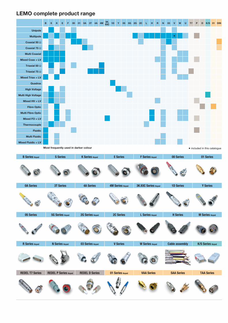
B Series Keyed S Series K Series Keyed E Series F Series Keyed 00 Series 01 Series
0A Series 3T Series 4A Series 4M Series Keyed 3K.93C Series Keyed 1D Series Y Series
05 Series 5G Series Keyed 2G Series Keyed 2C Series L Series Keyed H Series M Series Keyed
R Series Keyed N Series Keyed 03 Series Keyed V Series W Series Keyed Cable assembly K/S Series Keyed
REDEL T7 Series REDEL P Series Keyed REDEL D Series 01 Series Keyed VAA Series SAA Series TAA Series
LEMO complete product range
Unipole
Multipole
Coaxial 50 Ω
Coaxial 75 Ω
Multi Coaxial
Mixed Coax + LV
Triaxial 50 Ω
Triaxial 75 Ω
Mixed Triax + LV
Quadrax
High Voltage
Multi High Voltage
Mixed HV + LV
Fibre Optic
Multi Fibre Optic
Mixed FO + LV
Thermocouple
Fluidic
Multi Fluidic
Mixed Fluidic + LV
B S K E F 00 01 0A 3T 4A 4M 3K.93C 1D Y 05 5G 2G 2C L H R N 03 V W U T7 P D K/S 01 DIN
•
Most frequently used in darker colour • included in this catalogue
LEMO HEADQUARTERS
SWITZERLANDLEMO SA Chemin des Champs-Courbes 28 - P.O. Box 194 - CH-1024 EcublensTel. (+41 21) 695 16 00 - Fax (+41 21) 695 16 02 - e-mail: [email protected]
LEMO SUBSIDIARIES
LEMO DISTRIBUTORS
ARGENTINA, AUSTRALIA, BRAZIL, CHILE, COLOMBIA, CZECH REPUBLIC, GREECE, INDIA, ISRAEL, NEW ZEALAND, PERU, POLAND, RUSSIA, SOUTH AFRICA, SOUTH KOREA, TAIWAN, TURKEY, UKRAINE
www.lemo.com
AUSTRIALEMO Elektronik GesmbHLemböckgasse 49/E6-31230 WienTel: (+43 1) 914 23 20 0Fax:(+43 1) 914 23 20 [email protected]
BRAZILLEMO Latin America LtdaAv. José Rocha Bonfim, 214 Salas 224 / 225Condomínio Praça CapitalEd. ChicagoCampinas / SP - Brasil 13080-650Tel: +55 (11) 98689 [email protected]
CANADALEMO Canada Inc44 East Beaver Creek Road, unit 20Richmond Hill, Ontario L4B 1G8Tel: (+1 905) 889 56 78Fax: (+1 905) 889 49 [email protected]
CHINA / HONG KONGLEMO Electronics (Shanghai) Co., Ltd First Floor, Block E,18 Jindian Road, PudongShanghai, China, 201206Tel: (+86 21) 5899 7721Fax: (+86 21) 5899 [email protected]
DENMARKLEMO Denmark A/SMandal Allé 16A5500 MiddelfartTel: (+45) 45 20 44 00Fax: (+45) 45 20 44 [email protected]
FRANCELEMO France Sàrl24/28 Avenue Graham BellBâtiment Balthus 4Bussy Saint Georges77607 Marne la Vallée Cedex 3Tel: (+33 1) 60 94 60 94Fax: (+33 1) 60 94 60 [email protected]
GERMANYLEMO Elektronik GmbHHanns-Schwindt-Str. 681829 München Tel: (+49 89) 42 77 03Fax: (+49 89) 420 21 [email protected]
HUNGARYREDEL Elektronika KftNagysándor József u. 6-121201 BudapestTel: (+36 1) 421 47 10Fax: (+36 1) 421 47 [email protected]
ITALYLEMO Italia srlViale Lunigiana 2520125 MilanoTel: (+39 02) 66 71 10 46Fax: (+39 02) 37 90 80 [email protected]
JAPANLEMO Japan Ltd2-7-22, Mita, Minato-ku, Tokyo, 108-0073Tel: (+81 3) 54 46 55 10Fax: (+81 3) 54 46 55 [email protected]
MIDDLE EASTLEMO Middle East Connectors LLCConcorde Tower 6th Floor, Dubai Media City, P.O. Box 126732Dubai, United Arab EmiratesTel: +971 55 222 36 [email protected]
NETHERLANDS / BELGIUMLEMO Connectors Nederland B.V.Jacques Meuwissenweg 62031 AD HaarlemTel. +31 23 206 07 [email protected]
NORWAY / ICELANDLEMO Norway A/SSoerumsandvegen 69,1920 SoerumsandTel: (+47) 22 91 70 40Fax: (+47) 22 91 70 [email protected]
SINGAPORELEMO Asia Pte Ltd4 Leng Kee Road, #06-09 SiS Building Singapore 159088Tel: (+65) 6476 0672Fax: (+65) 6474 [email protected]
SPAIN / PORTUGALIBERLEMO SAUBrasil, 45, 08402 GranollersBarcelonaTel: (+34 93) 860 44 20Fax: (+34 93) 879 10 [email protected]
SWEDEN / FINLANDLEMO Nordic ABGunnebogatan 30, Box 8201 163 08 SpångaTel: (+46 8) 635 60 60Fax: (+46 8) 635 60 [email protected]
SWITZERLANDLEMO Verkauf AGGrundstrasse 22 B, 6343 RotkreuzTel: (+41 41) 790 49 [email protected]
UNITED KINGDOMLEMO UK Ltd12-20 North Street, Worthing, West Sussex, BN11 1DUTel: (+44 1903) 23 45 [email protected]
USALEMO USA IncP.O. Box 2408Rohnert Park, CA 94927-2408Tel: (+1 707) 578 88 11(+1 800) 444 53 66Fax:(+1 707) 578 08 [email protected]
CA
T.M
V.L
EN
.P1
00
6,
© L
EM
O /
Dat
a su
bje
ct t
o ch
ange
, prin
ted
in S
witz
erla
nd, u
pd
ated
Ju
ly 2
02
0