Embed Size (px)
Citation preview
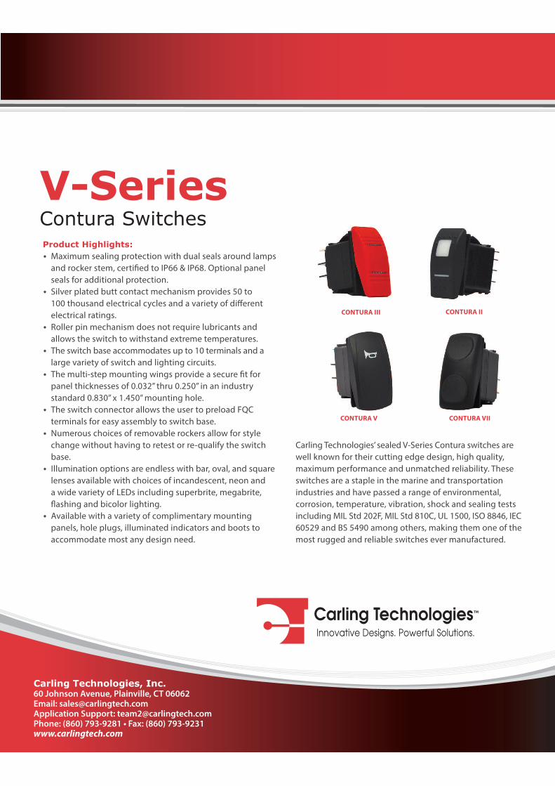
V-Series Contura Switches
Carling Technologies’ sealed V-Series Contura switches are
well known for their cutting edge design, high quality,
maximum performance and unmatched reliability. These
switches are a staple in the marine and transportation
industries and have passed a range of environmental,
corrosion, temperature, vibration, shock and sealing tests
including MIL Std 202F, MIL Std 810C, UL 1500, ISO 8846, IEC
60529 and BS 5490 among others, making them one of the
most rugged and reliable switches ever manufactured.
Product Highlights:
Maximum sealing protection with dual seals around lamps
and rocker stem, certi!ed to IP66 & IP68. Optional panel
seals for additional protection.
Silver plated butt contact mechanism provides 50 to
100 thousand electrical cycles and a variety of di"erent
electrical ratings.
Roller pin mechanism does not require lubricants and
allows the switch to withstand extreme temperatures.
The switch base accommodates up to 10 terminals and a
large variety of switch and lighting circuits.
The multi-step mounting wings provide a secure !t for
panel thicknesses of 0.032” thru 0.250” in an industry
standard 0.830” x 1.450” mounting hole.
The switch connector allows the user to preload FQC
terminals for easy assembly to switch base.
Numerous choices of removable rockers allow for style
change without having to retest or re-qualify the switch
base.
Illumination options are endless with bar, oval, and square
lenses available with choices of incandescent, neon and
a wide variety of LEDs including superbrite, megabrite,
#ashing and bicolor lighting.
Available with a variety of complimentary mounting
panels, hole plugs, illuminated indicators and boots to
accommodate most any design need.
CONTURA V CONTURA VII
CONTURA III CONTURA II
Carling Technologies, Inc.60 Johnson Avenue, Plainville, CT 06062 Email: [email protected] Support: [email protected]: (860) 793-9281 • Fax: (860) 793-9231www.carlingtech.com
Email: [email protected] • Application Support: [email protected] Phone: (860) 793–9281 • Fax: (860) 793–9231• www.carlingtech.com
2 | V-Series Contura Sealed Rocker Switches
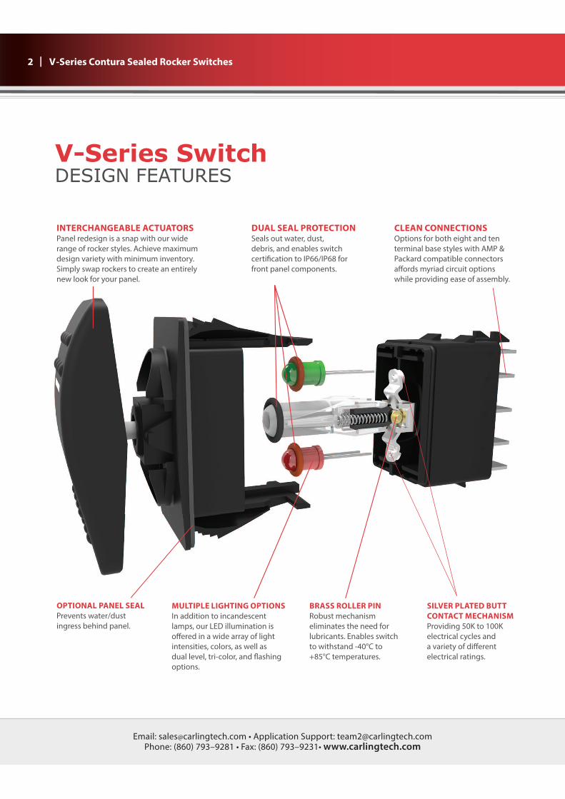
V-Series SwitchDESIGN FEATURES
INTERCHANGEABLE ACTUATORSPanel redesign is a snap with our wide
range of rocker styles. Achieve maximum
design variety with minimum inventory.
Simply swap rockers to create an entirely
new look for your panel.
DUAL SEAL PROTECTIONSeals out water, dust,
debris, and enables switch
certi!cation to IP66/IP68 for
front panel components.
CLEAN CONNECTIONSOptions for both eight and ten
terminal base styles with AMP &
Packard compatible connectors
a"ords myriad circuit options
while providing ease of assembly.
MULTIPLE LIGHTING OPTIONSIn addition to incandescent
lamps, our LED illumination is
o"ered in a wide array of light
intensities, colors, as well as
dual level, tri-color, and #ashing
options.
BRASS ROLLER PINRobust mechanism
eliminates the need for
lubricants. Enables switch
to withstand -40°C to
+85°C temperatures.
OPTIONAL PANEL SEALPrevents water/dust
ingress behind panel.
SILVER PLATED BUTT CONTACT MECHANISMProviding 50K to 100K
electrical cycles and
a variety of di"erent
electrical ratings.
Email: [email protected] • Application Support: [email protected] Phone: (860) 793–9281 • Fax: (860) 793–9231• www.carlingtech.com
| 3 V-Series Contura Sealed Rocker Switches & Illuminated Plug
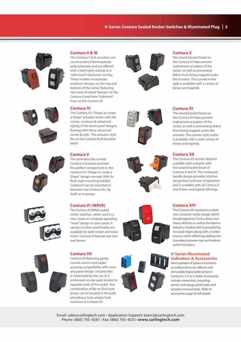
Contura II & IIIThe Contura II & III actuators are
constructed of thermoplastic
polycarbonate and are o!ered
with a hard nylon overlay or a
“soft-touch” elastomer overlay.
These models incorporate
aesthetic designs on the top and
bottom of the rocker featuring
two rows of raised “bumps” on the
Contura II and three “indented”
lines on the Contura III.
Contura IVThe Contura IV’s “Shape to create
a Shape” actuator works with the
curves, contours & advanced
styling of the latest panel designs,
"owing with these advanced
curves & radii. This actuator style
#ts on the Contura "ush bracket/
bezel.
Contura VThe symmetrically curved
Contura V actuator provides
the perfect complement to the
Contura IV’s “Shape to create a
Shape” design concept. With its
"ush style mounting bracket,
Contura V can be mounted in
between two Contura IV’s, by
itself, or in groups.
Contura VIIContura VII featuring gently
curved corners and edges
assuring compatibility with most
any panel design. Intuitive feel
is maximized by the use of 2
embossed circular pads located at
opposite ends of the rocker. Any
combination of Bar or Oval style
lenses can be located in the pads
providing a truly unique look,
exclusive to Contura VII.
Contura VI (WAVE)The Contura VI WAVE sealed
rocker switches, when used in a
row, create an uniquely appealing
“wave” design on your panel. A
variety of colors and #nishes are
available for both rocker and wave
insert. Contura VI features bar and
oval lenses.
Contura XThe raised bracket/bezel on
the Contura X helps prevent
inadvertent actuation of the
rocker, as well as preventing
debris from being trapped under
the actuator. This curved rocker
style is available with a variety of
lenses and legends.
Contura XIThe raised bracket/bezel on
the Contura XI helps prevent
inadvertent actuation of the
rocker, as well as preventing debris
from being trapped under the
actuator. This convex style rocker
is available with a wide variety of
lenses and legends.
Contura XIIThe Contura XII version features
a paddle style actuator with
the raised bracket/bezel of
Contura X and XI. The contoured
handle design provides intuitive
recognition and ease of operation
and is available with all Contura X
and XI lens and legend o!erings.
Contura XIVThe Contura XIV represents a sleek
new crossover rocker design which
should appeal to Trucks, Buses and
Heavy Vehicles as well as the Marine
Industry. Intuitive feel is provided by
recessed ridges along with a Center
Groove which e!ectively de#nes the
boundary between top and bottom
switch functions.
V-Series Illuminated Indicators & AccessoriesAlert operator of systems functions
or malfunctions, are o!ered with
removable/replaceable lamps in
Contura II, II, V or X styles. Accessories
include connectors, mounting
panels, hole plugs, panel seals, and
actuator removal tools. Refer to
accessories page for full details
Email: [email protected] • Application Support: [email protected] Phone: (860) 793–9281 • Fax: (860) 793–9231• www.carlingtech.com
4 | V–Series Contura Sealed Rocker Switches - General Speci�cations
1.450[36.83]
.830[21.08]
SWITCH
MOUNTING HOLE
TEST CUTHOLE INACTUAL
MATERIAL
Panel Thickness Range
Gaskets Acceptable Panel Thickness
0 .030 to .250 (.76mm to 6.35mm)
1 .030 to .109 & .147 to .157
(.76 to 2.77mm & 3.73 to 3.98mm)
Recommended: No gasket with panel
thickness of .032, .062, .093, .125,.187 or .250
Contact Rating .4VA @ 24VDC (MAX) resistive
15 amps, 125VAC
10 amps, 250VAC
1/2 HP 125-250VAC
20 amps, 4-14VDC
15 amps, 15-28VDC
10A, 14VT
6A, 125VAC L
Dielectric Strength 1500 Volts RMS
Insulation Resistance 50 Megohms
Initial Contact Resistance 10 milliohms max. @ 4VDC
Life 50,000- 100,000 cycles circuit
dependent
silver
Terminals Brass or copper/silver plate 1/4”
(6.3mm) Quick Connect
terminations standard. Solder lug,
Wire Lead
Endurance 150,000 cycles minimum
circuit dependent
2 position 18°
3 positions 9° from center
Lighted Incandescent - rated 10,000
hours Neon - rated 25,000 hours
LED - rated 100,000 hours 1/2 life
(LED is internally ballasted for
voltages to 24VDC)
Seals Internal
Optional external gasket panel seal
Base Polyester blend rated to 125°C with
Contura II,III,IV,V, Hard Surface: Basic actuator
VI, VII Actuator structure molded of thermoplastic
polycarbonate with a hard Nylon 66
thermoplastic surface overlay.
Soft Surface: Basic actuator structure
molded of thermoplastic polycarbonate
with an elastomer overlay.
Contura X,XI,XII Actuator,VP Nylon 66 Reinforced rated to 105°C
Lens Polycarbonate rated at 100°C
Contura XIV Polycarbonate lens/subrocker with
ABS shell
Sealing Sealed version: IP68, in accordance with IEC 60529, BS 5490, DIN 40050 & NFC 20 010. This rating applies to front panel components of the actual
against dust and the prolonged effects of immersion under pressure. The standard test for immersion under pressure requires submersion under one meter of water for 30 min. The V-Series switch has exceeded these parameters, having been actuated and illuminated during submersion. Corrosion Mixed Flowing Gas (MFG) Class III 3 year accelerated exposure per ASTM B-827, B-845 Silver and gold contactsOperating Temp. -40°C to +85°CVibration 1 Per Mil-Std 202F, Method 204D Test Condition A 0.06 DA or 10G’s 10-500 Hz. Tested with VCH connector. Test criteria - No loss of circuit during test, pre and post test contact resistance.Vibration 2 Resonance search 24-50 Hz 0.40 DA 50-2000 Hz ±10 G’s peak Horizontal Axis 3-5 G’s max. Random 24 Hz 0.06 PSD-Gsq/Hz 60 Hz 0.50 100 Hz 0.50 200 Hz 0.025 2000 Hz 0.025
seconds chatter.Shock Per Mil-Std 202F, Method 213B, Test Condition K @ 30G’s. Tested with VCH connector. Test criteria - No loss of circuit during test, pre and post test contact resistance.Salt Spray Per Mil-Std 202F, Method 101D, Test Condition A, 96 Hrs. Sealed version only.Dust Per Mil-Std 810C, Method 510.2 Air Velocity 300 ±200 Feet/Min, Test Duration 16 Hrs.Thermal Shock Per Mil-Std 202F, Method 107F, Test Cond. A, -55°C to +85°C. Test criteria - pre and post test contact resistanceMoisture Resistance Per Mil-Std 202F, Method 106F, Test Criteria - pre and post test contact resistanceIgnition Protection All Contura switches with sealed construction meet the requirements of UL1500/ISO8846 for ignition protection, in addition to conformance with EC directive 94/25/EC for marine products.
Electrical Agency Certifications
Environmental
Mechanical
Actuator Travel (Angular Displacement)
Mounting Specifications
Physical
Email: [email protected] • Application Support: [email protected] Phone: (860) 793–9281 • Fax: (860) 793–9231• www.carlingtech.com
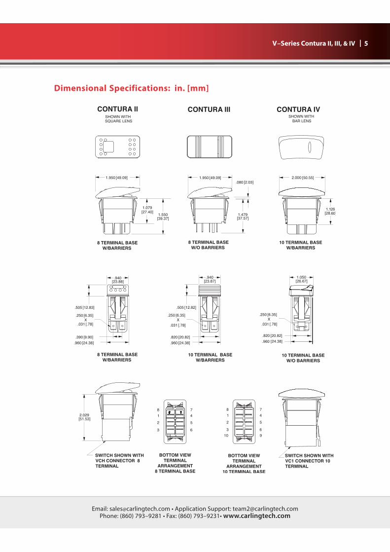
| 5 V–Series Contura II, III, & IV
Dimensional Specifications: in. [mm]
Email: [email protected] • Application Support: [email protected] Phone: (860) 793–9281 • Fax: (860) 793–9231• www.carlingtech.com
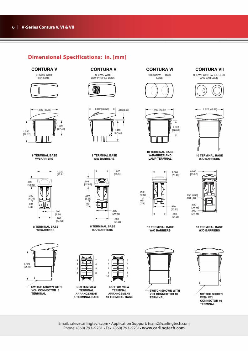
6 | V-Series Contura V, VI & VII
1.079
[27.40]
.505
[12.83].505
[12.83]
8
1
7
4
78
41
36
9
63
.250
[6.35] X
.031
[.78]
.250
[6.35] X
.031
[.78]
CONTURA V
SHOWN WITH
LOW PROFILE LOCK
8 TERMINAL BASE
W/O BARRIERS
8 TERMINAL BASE
W/O BARRIERS
10
BOTTOM VIEW
TERMINAL
ARRANGEMENT
10 TERMINAL BASE
BOTTOM VIEW
TERMINAL
ARRANGEMENT
8 TERMINAL BASE
.820
[20.83]
1.020
[25.91]
1.479
[37.57]
1.922 [48.56]
1.126
[28.60]
.080[2.03]
52 25
2.029
[51.53]
CONTURA V
SHOWN WITH
BAR LENS
1.020
[25.91]
1.550
[39.37]
1.922 [48.56]
8 TERMINAL BASE
W/BARRIERS
8 TERMINAL BASE
W/BARRIERS
.390
[9.90]
SWITCH SHOWN WITH
VCH CONNECTOR 8
TERMINAL
.960
[24.38].960
[24.38]
.250
[6.35]
X
.031
[.78]
.820
[20.83]
.960
[24.38]
1.000
[25.40]
1.950 [49.53]
SWITCH SHOWN WITH
VC1 CONNECTOR 10
TERMINAL
10 TERMINAL BASE
W/BARRIER AND
LAMP TERMINAL
10 TERMINAL BASE
W/O BARRIERS
CONTURA VI
SHOWN WITH OVAL
LENS
CONTURA VII
SHOWN WITH LARGE LENS
AND BAR LENS
10 TERMINAL BASE
W/O BARRIERS
1.922 [48.82]
10 TERMINAL BASE
W/O BARRIERS
0.985
[25.02]
.250 [6.35]
.031 [.78]
.820
[20.83]
.960
[24.38]
SWITCH SHOWN
WITH VC1
CONNECTOR 10
TERMINAL
Dimensional Specifications: in. [mm]
Email: [email protected] • Application Support: [email protected] Phone: (860) 793–9281 • Fax: (860) 793–9231• www.carlingtech.com
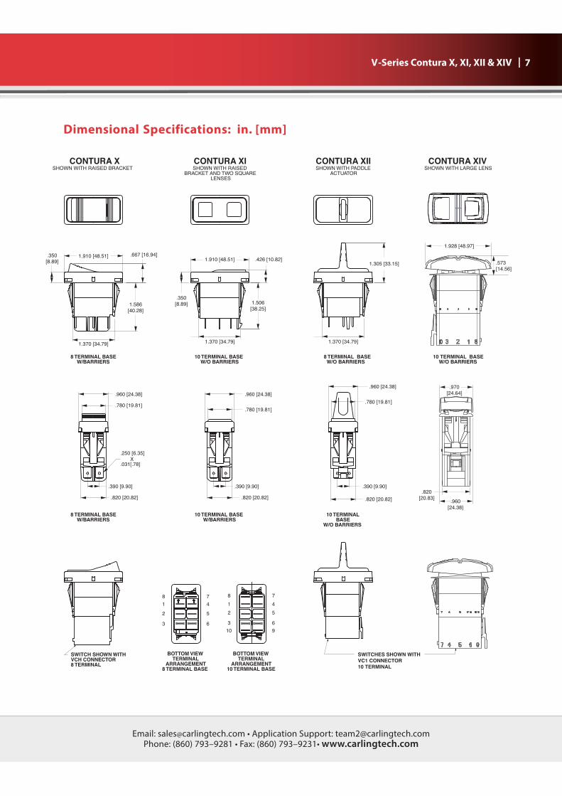
| 7 V-Series Contura X, XI, XII & XIV
10 TERMINAL BASE
W/O BARRIERS
CONTURA XISHOWN WITH RAISED
BRACKET AND TWO SQUARELENSES
10
8
2
1
9
4
7
63
5
BOTTOM VIEW
TERMINAL
ARRANGEMENT
10 TERMINAL BASE
1
8
2
7
4
5
3 6
BOTTOM VIEW
TERMINAL
ARRANGEMENT
8 TERMINAL BASE
1.506
[38.25]
.350
[8.89]
1.370 [34.79]
10 TERMINAL BASE
W/O BARRIERS
.426 [10.82]1.910 [48.51]
CONTURA XSHOWN WITH RAISED BRACKET
1.586
[40.28]
.350
[8.89]
.667 [16.94]
8 TERMINAL BASE
W/BARRIERS
1.910 [48.51]
1.370 [34.79]
SWITCH SHOWN WITH
VCH CONNECTOR
8 TERMINAL
CONTURA XIISHOWN WITH PADDLE
ACTUATOR
CONTURA XIVSHOWN WITH LARGE LENS
.390 [9.90]
10 TERMINAL BASE
W/BARRIERS
.780 [19.81]
.820 [20.82]
.960 [24.38]
.780 [19.81]
10 TERMINAL
BASE
W/O BARRIERS
.390 [9.90]
.820 [20.82]
.960 [24.38]
.250 [6.35]
X.031[.78]
8 TERMINAL BASE
W/BARRIERS
.780 [19.81]
.820 [20.82]
.390 [9.90]
.960 [24.38]
SWITCHES SHOWN WITH
VC1 CONNECTOR
10 TERMINAL
8 TERMINAL BASE
W/O BARRIERS
1.305 [33.15]
1.370 [34.79]
.960
[24.38]
.820
[20.83]
.970
[24.64]
1.928 [48.97]
.573
[14.56]
Dimensional Specifications: in. [mm]
Email: [email protected] • Application Support: [email protected] Phone: (860) 793–9281 • Fax: (860) 793–9231• www.carlingtech.com
2 5
1 3 4 6
6431
DEFINITION
CIRCUITCIRCUIT
A J
3
2 5
3
63
2
3 4 6
L
M
5
52
K
1
52
D
431
C
3
2
B
5
2
3
CIRCUIT
1
3
3
3
2
2
2
4
1 3
31
R
2 5
52
1 3 6
S
6
F
1 3
E
52
2 5
3
43
4
1
SYM.
43
2 5
H
2 5
1 3
6
1 3
31
2
2
5
8
2
31
6
CIRCUIT DIAGRAM
2
6
6
6
6
6
6
G
CIRCUIT DIAGRAM
7
52522
CIRCUIT DIAGRAM
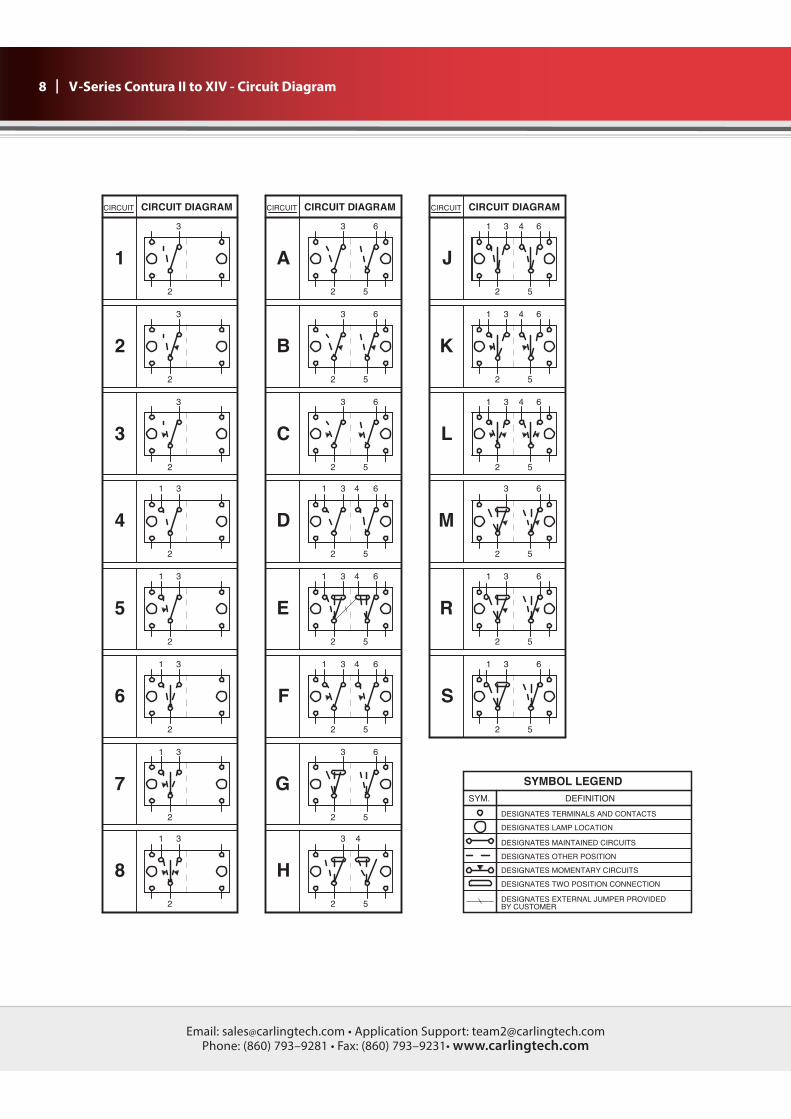
SYMBOL LEGEND
DESIGNATES TERMINALS AND CONTACTS
DESIGNATES LAMP LOCATION
DESIGNATES MAINTAINED CIRCUITS
DESIGNATES OTHER POSITION
DESIGNATES MOMENTARY CIRCUITS
DESIGNATES TWO POSITION CONNECTION
DESIGNATES EXTERNAL JUMPER PROVIDED
BY CUSTOMER
8 | V-Series Contura II to XIV - Circuit Diagram
Email: [email protected] • Application Support: [email protected] Phone: (860) 793–9281 • Fax: (860) 793–9231• www.carlingtech.com
| 9 V-Series Contura II to XIV - Circuit Diagram
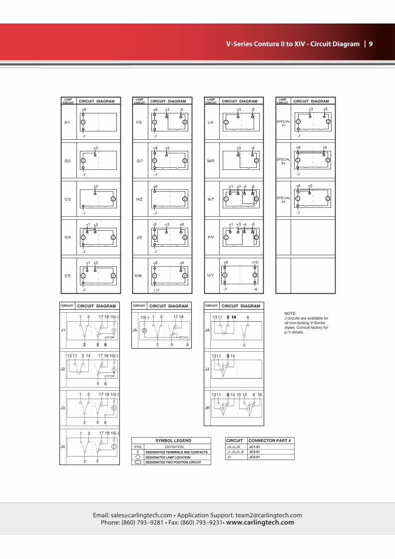
1
LAMP
CIRCUITCIRCUIT DIAGRAM
+3
+3 -6
CIRCUIT DIAGRAMLAMP
CIRCUIT
1L/9
2
-6
+8 +3
-7
SPECIAL#4
21
SPECIAL#1
2
-7
+6+3
1
+6+8
2SPECIAL#3
+10
21
2
-4 -6+3+1
1
+8
G/7
F/6
+3
1 2
+8
1
-7
+8 -6+3
2
CIRCUIT DIAGRAMLAMP
CIRCUIT
M/R
+8
LAMP
CIRCUIT
1
-7
1
+3
J/8
H/Z
+8
+6
-7
1 2
-8 +6
2
-7
+3
+8
P/V
N/T
+1 -6+3 -4
CIRCUIT DIAGRAMCIRCUIT
-7 -9
1 2
D/4
C/3
-7
+1
-7
+3
+3
1
+3
+1
B/2
A/1
1 21
-7
K/W
CIRCUIT CIRCUIT DIAGRAM
(-)7
E/5
CIRCUIT
2
CIRCUIT DIAGRAM
2
2
-7 -7 -7
U/Y
CIRCUIT DIAGRAM
CONNECTOR PART #
16
3
14143
5
CIRCUIT DIAGRAM
14 633
14
3 14
333
JA,JJ,JK
J2
CIRCUIT
J1,J3,J4,J5
22 8855
3
17 18
5 8
2
2
10(-) 1 3
CIRCUIT DIAGRAM
JA
612153333 14
85
3
SYMBOL LEGEND
DEFINITION
JK
JJ
1
17 18 10(-)
17 18 10(-)
CIRCUIT DIAGRAM
14
31
1311
CIRCUIT
13 11
1113
SYM.
CIRCUIT
J5
1
1
17 18 10(-)
17 18 10(-)
1
1
2 5 8
2
31
5JC3-01
JC2-01
JC1-01
J3
J4
J2
CIRCUIT
J1
DESIGNATES TERMINALS AND CONTACTS
DESIGNATES LAMP LOCATION
DESIGNATES TWO POSITION CIRCUIT
DESIGNATES TERMINALS AND CONTACTS
DESIGNATES LAMP LOCATION
DESIGNATES TWO POSITION CIRCUIT
1113
NOTE:
J circuits are available for
all non-locking V-Series
styles. Consult factory for
p/n details.
Email: [email protected] • Application Support: [email protected] Phone: (860) 793–9281 • Fax: (860) 793–9231• www.carlingtech.com
10 |
10 LENS0 - No Actuator Z - No LensClear White Amber Green Red Blue
1 6 8 G M T
2 7 C H N U
3 8 D J P V
4 9 E K R W
5 A F L S Y
Lens color for LEDs must be clear, white, or match color of LED.Green or blue lenses are not recommended with Neon lamps.
9 ACTUATOR0 No ActuatorA, B Contura IIC, D Contura III
Actuator orientation above terminals:
V-Series Contura II & III Sealed Rocker Switches - Ordering Scheme
1
Series
2
Circuit
3
Rating
5
Illumination
6
Lamp
7
Lamp
8
Bracket
9
Actuator
10
Lens
11
Color
12
Legend
13
Legend
Orientation
14
Actuator
Lens Legend
4
Termination
V 1 A B A R 00 00D T 0 B B 0
1 SERIESV
3 RATING3
1 .4VA @ 28VDC ResistiveB 15A 24VC 20A 18VD 20A 12VE 20A 14V, 10A 14VT (circuit 1, 4 , A & D only)F 10A 14V, 6A 14VT (circuit G only)M .4VA/20A 12VN .4VA/15A 24V
11 ACTUATOR COLOR1 AND TEXTURE0 - No Actuator Black Gray Red WhiteSoft Surface B G R WHard Surface C H S Y
13 LEGEND ORIENTATION0 No legend (used with codes 11-18 in selection 12)1 Orientation 12 Orientation 2 3 Orientation 34 Orientation 4
14 ACTUATOR LENS LEGEND00 No legend this location / no actuator(used with codes 11-18 in selection 12) Selection 14 required when switch requires two legends. If the two legends consist of one lens and one body legend, lens legend must
For legend options & codes, visit us at www.carlingtech.com.
1,43,6
Notes: Consult factory to verify horsepower rating for your particular circuit choice.1 Custom colors are available. Consult factory.2
Custom colors are available, consult factory.3 Additional ratings available. See V-Series Switch Accessories page.4 Contura II available with two square lenses. Consult factory for details.
2 CIRCUIT Terminal Connections as viewed ( ) - momentary from bottom of switch: SP - single pole - uses terminals 1, 2 & 3. 8 terminal 10 terminal DP - double pole uses terminals 1, 2, 3, 4, 5 & 6. 8 - - 7 8 - - 7 Terminals 7, 8, 9 & 10 for lamp circuit only. 1 - - 4 1 - - 4 2 - - 5 2 - - 5 3 - - 6 3 - - 6 10 - - 9 Position: 1 2 3 SP DP 2 & 3, 5 & 6 Connected Terminals 1 & 2, 4 & 5 1 A ON NONE OFF 2 B (ON) NONE OFF 3 C ON NONE (OFF) 4 D ON NONE ON 5 F ON NONE (ON) 6 J ON OFF ON 7 K ON OFF (ON) 8 L (ON) OFF (ON) SPECIAL CIRCUITS H* 2 & 3 2 & 3, 5 & 4 5 & 4 G* 2 & 3, 5 & 6 2 & 3 OFF S* 2 & 3, 5 & 6 2 & 3 1 & 2 M* (2 & 3, 5 & 6) 2 & 3 OFF R* (2 & 3, 5 & 6) 2 & 3 2 & 1 E* 5 & 6 5 & 3 5 & 1
External jumper between terminals 2 & 4 for circuit E are provided by customer. Circuit E may be used for SP OFF-ON-ON circuit.
4 TERMINATION/BASE STYLE8 term 10 Term Termination Jumper1 2 .250 TAB (QC) no barriers NoA B .250 TAB (QC) with barriers NoJ K .250 TAB (QC) no barriers Yes T2 to 53 5 Solder Lug no barriers NoC D Solder Lug No5 6 Wire Leads no barriers NoE F Wire Leads NoNote: Codes J & K for circuits H, G & M.
5 ILLUMINATION
switch. Positive (+) and negative (-) symbols apply to LED lamps onlySealed Unsealed Lamps Illumination Type Lamp wired to TerminalsS 0 NONE – –A 1 1 INDEPENDENT 8 (+) 7 (–)B 2 1 DOWN 3 (+) 7 (–)C 3 2 UP 3 (+) 7 (–)D 4 1 DOWN 3 (+) 7 (–) 2 DOWN 1 (+) 7 (–)E 5 1 UP 1 (+) 7 (–) 2 UP 3 (+) 7 (–)F 6 1 INDEPENDENT 8 (+) 7 (–) 2 UP 3 (+) 6 (–)G 7 1 INDEPENDENT 8 (+) 7 (–) 2 UP 3 (+) 7 (–)H Z 2 INDEPENDENT 8 (+) 7 (–)U Y 1 INDEPENDENT 8 (+) 7 (–) 2 INDEPENDENT 10 (+) 9 (–)SINGLE POLE SWITCHES ONLYJ 8 1 DOWN 3 (+) 8 (–) 2 INDEPENDENT 6 (+) 7 (–)K W 1 INDEPENDENT 8 (+) 7 (–) 2 INDEPENDENT 6 (+) 7 (–)DOUBLE POLE SWITCHES ONLYL 9 1 DOWN 3 (+) 6 (–)M R 1 UP 3 (+) 6 (–)N T 1 DOWN 3 (+) 6 (–) 2 DOWN 1 (+) 4 (–)P V 1 UP 1 (+) 4 (–) 2 UP 3 (+) 6 (–)
8 FLUSH BRACKET COLOR1, PANEL SEAL Black White Gray No Seal B W GOne Seal C Y H
6,7 LAMP (SAME CODING FOR BOTH SELECTIONS)
No lamp 0Neon 1 125VAC 2 250VACIncandescent 4 3V 5 6V 6 12V 7 18V 8 24VLED* superbright superbright Red Amber Green Red2VDC A L F R6VDC B M G S12VDC C N H T24VDC D P J V* Consult factory for “daylight bright” LED options. Typical current draw for LED is 20ma.
12 ACTUATOR LENS OR BODY LEGENDS2
11 ON 12 OFF 13 I 14 O
OFF ON O I
15 O O 16 O O 17 O I 18 I O F N N F F F For additional legend options & codes, visit us at www.carlingtech.com.
Email: [email protected] • Application Support: [email protected] Phone: (860) 793–9281 • Fax: (860) 793–9231• www.carlingtech.com
| 13
12 ACTUATOR LENS OR BODY LEGENDS2,6
11 ON 12 OFF 13 I 14 O
OFF ON O I
15 O O 16 O O 17 O I 18 I O F N N F F F For additional legend options & codes, visit us at www.carlingtech.com.
V-Series Contura V Sealed Rocker Switches - Ordering Scheme
1
Series
2
Circuit
3
Rating
5
Illumination
6
Lamp
7
Lamp
8
Bracket
9
Actuator
10
Lens
11
Color
12
Legend
13
Legend
Orientation
14
Actuator
Lens Legend
4
Termination
V 1 A B G P 00 00D T 0 B C 0
1 SERIESV
3 RATING4
1 .4VA @ 28VDC ResistiveB 15A 24VC 20A 18VD 20A 12VE 20A 14V, 10A 14VT (circuit 1, 4 , A & D only)F 10A 14V, 6A 14VT (circuit G only)M .4VA/20A 12VN .4VA/15A 24V
9 ACTUATOR0 No Actuator G Contura VP Contura V, laser etched
11 ACTUATOR COLOR1,3,3
No Actuator 0 Black C Gray H Red S White Y Nickel D Pewter E
13 LEGEND ORIENTATION0 No legend (used with codes 11-18 in selection 12)1 Orientation 12 Orientation 2 3 Orientation 34 Orientation 4
ORIENTATION 4
ORIENTATION 3
ORIENTATION 1
ORIENTATION OF
ACTUATOR/LENS IN PANEL
ORIENTATION 2
4G13L
MA1MC
4G
MC
MA
4G
3L
4G200
MC
MA
MA3MC
14 ACTUATOR LENS LEGEND00 No legend this location / no actuator(used with codes 11-18 in selection 12) Selection 14 required when switch requires two legends. If the two legends consist of one lens and one body legend, lens legend must
For legend options & codes, visit us at www.carlingtech.com.
Notes: Consult factory to verify horsepower rating for your particular circuit choice.1 Custom colors are available. Consult factory.2 white, red and gray actuators. Custom colors are available, consult factory.3 Laser Etched rocker only available with lens code Z & actuator colors black, nickel or pewter.4 Additional ratings available. See V-Series Switch Accessories page.5 Nickel and Pewter colors only available with laser etched actuator.6 Consult factory for laser etched lens callout.
2 CIRCUIT Terminal Connections as viewed ( ) - momentary from bottom of switch: SP - single pole - uses terminals 1, 2 & 3. 8 terminal 10 terminal DP - double pole uses terminals 1, 2, 3, 4, 5 & 6. 8 - - 7 8 - - 7 Terminals 7, 8, 9 & 10 for lamp circuit only. 1 - - 4 1 - - 4 2 - - 5 2 - - 5 3 - - 6 3 - - 6 10 - - 9 Position: 1 2 3 SP DP 2 & 3, 5 & 6 Connected Terminals 1 & 2, 4 & 5 1 A ON NONE OFF 2 B (ON) NONE OFF 3 C ON NONE (OFF) 4 D ON NONE ON 5 F ON NONE (ON) 6 J ON OFF ON 7 K ON OFF (ON) 8 L (ON) OFF (ON) SPECIAL CIRCUITS H* 2 & 3 2 & 3, 5 & 4 5 & 4 G* 2 & 3, 5 & 6 2 & 3 OFF S* 2 & 3, 5 & 6 2 & 3 1 & 2 M* (2 & 3, 5 & 6) 2 & 3 OFF R* (2 & 3, 5 & 6) 2 & 3 2 & 1 E* 5 & 6 5 & 3 5 & 1
External jumper between terminals 2 & 4 for circuit E are provided by customer. Circuit E may be used for SP OFF-ON-ON circuit.
4 TERMINATION/BASE STYLE8 term 10 Term Termination Jumper1 2 .250 TAB (QC) no barriers NoA B .250 TAB (QC) with barriers NoJ K .250 TAB (QC) no barriers Yes T2 to 53 5 Solder Lug no barriers NoC D Solder Lug No5 6 Wire Leads no barriers NoE F Wire Leads NoNote: Codes J & K for circuits H, G & M.
5 ILLUMINATION & SWITCH SEALING
switch. Positive (+) and negative (-) symbols apply to LED lamps onlySealed Unsealed Lamps Illumination Type Lamp wired to TerminalsS 0 NONE – –A 1 1 INDEPENDENT 8 (+) 7 (–)B 2 1 DOWN 3 (+) 7 (–)C 3 2 UP 3 (+) 7 (–)D 4 1 DOWN 3 (+) 7 (–) 2 DOWN 1 (+) 7 (–)E 5 1 UP 1 (+) 7 (–) 2 UP 3 (+) 7 (–)F 6 1 INDEPENDENT 8 (+) 7 (–) 2 UP 3 (+) 6 (–)G 7 1 INDEPENDENT 8 (+) 7 (–) 2 UP 3 (+) 7 (–)H Z 2 INDEPENDENT 8 (+) 7 (–)U Y 1 INDEPENDENT 8 (+) 7 (–) 2 INDEPENDENT 10 (+) 9 (–)SINGLE POLE SWITCHES ONLYJ 8 1 DOWN 3 (+) 8 (–) 2 INDEPENDENT 6 (+) 7 (–)K W 1 INDEPENDENT 8 (+) 7 (–) 2 INDEPENDENT 6 (+) 7 (–)DOUBLE POLE SWITCHES ONLYL 9 1 DOWN 3 (+) 6 (–)M R 1 UP 3 (+) 6 (–)N T 1 DOWN 3 (+) 6 (–) 2 DOWN 1 (+) 4 (–)P V 1 UP 1 (+) 4 (–) 2 UP 3 (+) 6 (–)
8 FLUSH BRACKET COLOR1, PANEL SEAL Black White Gray No Seal B W GOne Seal C Y H
6,7 LAMP (SAME CODING FOR BOTH SELECTIONS)
No lamp 0Neon 1 125VAC 2 250VACIncandescent 4 3V 5 6V 6 12V 7 18V 8 24VLED* superbright superbright Red Amber Green Red2VDC A L F R6VDC B M G S12VDC C N H T24VDC D P J V* Consult factory for “daylight bright” LED options. Typical current draw for LED is 20ma.
10 Lens0 - No Actuator Z - No Lens Clear White Amber Green Red Blue
1 6 8 G M T bar
2 7 C H N U bar/bar
3 8 D J P V oval
4 9 E K R W oval/bar
5 A F L S Y oval/oval
Lens color for LEDs must be clear, white, or match color of LED.Green or blue lenses are not recommended with Neon lamps.
Email: [email protected] • Application Support: [email protected] Phone: (860) 793–9281 • Fax: (860) 793–9231• www.carlingtech.com
22 | V-Series Contura Sealed Rocker Switch Accessories
DETAIL VIEWVH2,VH4 & VH6
HOLE PLUGS(With wing serrations)
.830 [21.08] VHPCONTURA II,III HOLE PLUG
1.820 [46.23]
.430 [10.92]VHP
CONTURA II,III HOLE PLUG
VH3CONTURA IV HOLE PLUG
(No wing serrations)
VH5CONTURA V HOLE PLUG
(No wing serrations)
DETAIL VIEWVH1,VH3 & VH5
HOLE PLUGS(No wing serrationsfor ease of removal)
VH1STANDARD HOLE PLUG
(No wing serrations)(With VC1 connector attached)
TEST CUTHOLE INACTUAL
MATERIAL
1.450 [36.83]
VH6CONTURA V HOLE PLUG
(With wing serrations)
VH4CONTURA IV HOLE PLUG
(With wing serrations)
1.020 [25.91]
1.240 [31.50]
VH2STANDARD HOLE PLUG
(With wing serrations)
2.000 [50.80]
1.067 [27.10]
1.928 [48.97]
Contura Hole PlugDimensional Specifications: in. [mm]
Contura Mounting PanelsDimensional Specifications: in. [mm]