Embed Size (px)
Citation preview

V17.2.00


Preface
NoticeThe company reserves the right to revise this publication or to change its contents without notice. Informationcontained herein is for reference only and does not constitute a commitment on the part of the manufacturer orany subsequent vendor. They assume no responsibility or liability for any errors or inaccuracies that may appearin this publication nor are they in anyway responsible for any loss or damage resulting from the use (or misuse)of this publication.This publication and any accompanying software may not, in whole or in part, be reproduced, translated, trans-mitted or reduced to any machine readable form without prior consent from the vendor, manufacturer or creatorsof this publication, except for copies kept by the user for backup purposes.Brand and product names mentioned in this publication may or may not be copyrights and/or registered trade-marks of their respective companies. They are mentioned for identification purposes only and are not intendedas an endorsement of that product or its manufacturer.©November 2017
TrademarksIntel, Pentium and Intel Core are trademarks/registered trademarks of Intel Corporation.
I

Preface
R&TTE DirectiveThis device is in compliance with the essential requirements and other relevant provisions of the R&TTE Direc-tive 1999/5/EC.
This device will be sold in the following EEA countries: Austria, Italy, Belgium, Liechtenstein, Denmark, Lux-embourg, Finland, Netherlands, France, Norway, Germany, Portugal, Greece, Spain, Iceland, Sweden, Ireland,United Kingdom, Cyprus, Czech Republic, Estonia, Hungary, Latvia, Lithuania, Malta, Slovakia, Poland, Slov-enia.
ErP Off Mode Power Consumption Statement:The figures below note the power consumption of this computer in compliance with European Commission (EC)regulations on power consumption in off mode:
• Off Mode < 0.5W
II

Preface
CE MarkingThis device has been tested to and conforms to the regulatory requirements of the European Union and has at-tained CE Marking. The CE Mark is a conformity marking consisting of the letters “CE”. The CE Mark appliesto products regulated by certain European health, safety and environmental protection legislation. The CE Markis obligatory for products it applies to: the manufacturer affixes the marking in order to be allowed to sell hisproduct in the European market.
This product conforms to the essential requirements of the R&TTE directive 1999/5/EC in order to attain CEMarking. A notified body has determined that this device has properly demonstrated that the requirements of thedirective have been met and has issued a favorable certificate of expert opinion. As such the device will bear thenotified body number 0560 after the CE mark.
The CE Marking is not a quality mark. Foremost, it refers to the safety rather than to the quality of a product.Secondly, CE Marking is mandatory for the product it applies to, whereas most quality markings are voluntary.
III

Preface
FCC Statement(Federal Communications Commission)You are cautioned that changes or modifications not expressly approved by the party responsible for compliancecould void the user's authority to operate the equipment.
This equipment has been tested and found to comply with the limits for a Class B digital device, pursuant to Part15 of the FCC Rules. These limits are designed to provide reasonable protection against harmful interference ina residential installation. This equipment generates, uses and can radiate radio frequency energy and, if not in-stalled and used in accordance with the instructions, may cause harmful interference to radio communications.However, there is no guarantee that interference will not occur in a particular installation. If this equipment doescause harmful interference to radio or television reception, which can be determined by turning the equipmentoff and on, the user is encouraged to try to correct the interference by one or more of the following measures:
• Re orient or relocate the receiving antenna.• Increase the separation between the equipment and receiver.• Connect the equipment into an outlet on a circuit different from that to which the receiver is connected.• Consult the service representative or an experienced radio/TV technician for help.
Operation is subject to the following two conditions:
1. This device may not cause interference.
And
2. This device must accept any interference, including interference that may cause undesired operation of the device.
IV

Preface
FCC RF Radiation Exposure Statement:
1. This Transmitter must not be co-located or operating in conjunction with any other antenna or transmitter.
2. This equipment complies with FCC RF radiation exposure limits set forth for an uncontrolled environment. This equipment should be installed and operated with a minimum distance of 20 centimeters between the radiator and your body.
Warning
Use only shielded cables to connect I/O devices to this equipment. You are cautioned that changes or modifications not ex-pressly approved by the manufacturer for compliance with the above standards could void your authority to operate theequipment.
V

Preface
IMPORTANT SAFETY INSTRUCTIONSFollow basic safety precautions, including those listed below, to reduce the risk of fire, electric shock, and injuryto persons when using any electrical equipment:
1. Do not use this product near water, for example near a bath tub, wash bowl, kitchen sink or laundry tub, in a wet basement or near a swimming pool.
2. Avoid using this equipment with a telephone line (other than a cordless type) during an electrical storm. There may be a remote risk of electrical shock from lightning.
3. Do not use the telephone to report a gas leak in the vicinity of the leak.4. Use only the power cord and batteries indicated in this manual. Do not dispose of batteries in a fire. They may
explode. Check with local codes for possible special disposal instructions.5. This product is intended to be supplied by a Listed Power Unit according to the model’s requirements:
• Full Range AC/DC Adapter - AC Input of 100 - 240V, 50 - 60Hz, DC Output of 19V, 3.42A (65 Watts) minimum AC/DC Adapter.
This Computer’s Optical Device is a Laser Class 1 Product
VI

Preface
Instructions for Care and OperationThe notebook computer is quite rugged, but it can be damaged. To prevent this, follow these suggestions:
1. Don’t drop it, or expose it to shock. If the computer falls, the case and the components could be damaged.
2. Keep it dry, and don’t overheat it. Keep the computer and power supply away from any kind of heating ele-ment. This is an electrical appliance. If water or any other liquid gets into it, the computer could be badly dam-aged.
Do not expose the computer to any shock or vibration.
Do not place it on an unstable surface.
Do not place anything heavy on the computer.
Do not expose it to excessive heat or direct sunlight.
Do not leave it in a place where foreign matter or mois-ture may affect the system.
Don’t use or store the com-puter in a humid environment.
Do not place the computer on any surface that will block the Vents/Fan Intakes.
VII
Preface
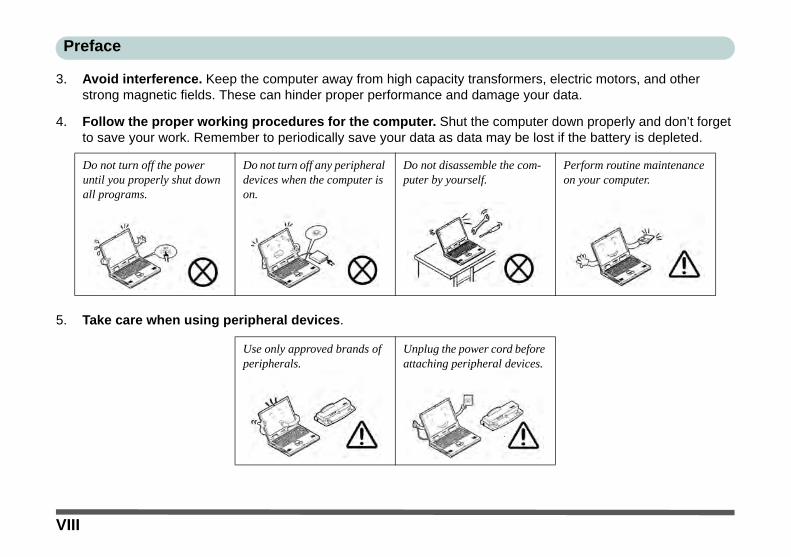
3. Avoid interference. Keep the computer away from high capacity transformers, electric motors, and other strong magnetic fields. These can hinder proper performance and damage your data.
4. Follow the proper working procedures for the computer. Shut the computer down properly and don’t forget to save your work. Remember to periodically save your data as data may be lost if the battery is depleted.
5. Take care when using peripheral devices.
Do not turn off the power until you properly shut down all programs.
Do not turn off any peripheral devices when the computer is on.
Do not disassemble the com-puter by yourself.
Perform routine maintenance on your computer.
Use only approved brands of peripherals.
Unplug the power cord before attaching peripheral devices.
VIII

Preface
ServicingDo not attempt to service the computer yourself. Doing so may violate your warranty and may expose you andthe computer to electric shock. Refer all servicing to authorized service personnel. Unplug the computer fromthe power supply. Then refer servicing to qualified service personnel under any of the following conditions:
• When the power cord or AC/DC adapter is damaged or frayed.• If the computer has been exposed to rain or other liquids.• If the computer does not work normally when you follow the operating instructions.• If the computer has been dropped or damaged (do not touch the poisonous liquid if the LCD panel breaks).• If there is an unusual odor, heat or smoke coming from your computer.
Bottom Cover Removal Warning
Do not remove any cover(s) and /or screw(s) for the purposes of device upgrade as this may violate the terms of your war-ranty. If you need to replace/remove the hard disk/RAM/optical device etc., for any reason, please contact your distributor/supplier for further information.
Removal Warning (For Service Personnel)
When removing any cover(s) and screw(s) for the purposes of device upgrade, remember to replace the cover(s) andscrew(s) before restoring power to the system.
Also note the following when the cover is removed:
• Hazardous moving parts.• Keep away from moving fan blades.
IX

Preface
Power SafetyThe computer has specific power requirements:
• Only use a power adapter approved for use with this computer.• Your AC/DC adapter may be designed for international travel but it still requires a
steady, uninterrupted power supply. If you are unsure of your local power specifica-tions, consult your service representative or local power company.
• The power adapter may have either a 2-prong or a 3-prong grounded plug. The third prong is an important safety feature; do not defeat its purpose. If you do not have access to a compatible outlet, have a qualified electrician install one.
• When you want to unplug the power cord, be sure to disconnect it by the plug head, not by its wire.
• Make sure the socket and any extension cord(s) you use can support the total current load of all the connected devices.
• Before cleaning the computer, make sure it is disconnected from any external power supplies (i.e. AC/DC adapter or car adapter).
Do not plug in the power cord if you are wet.
Do not use the power cord if it is broken.
Do not place heavy objects on the power cord.
Power Safety Warning
(For Service Personnel)
Before you undertakeany upgrade proce-dures, make sure thatyou have turned off thepower, and disconnect-ed all peripherals andcables (including tele-phone lines and powercord).
You must also removeyour battery in order toprevent accidentallyturning the machine on.Before removing thebattery disconnect theAC/DC adapter fromthe computer.
X
Preface
Polymer Battery PrecautionsNote the following information which is specific to polymer batteries only, and where applicable, this overridesthe general battery precaution information overleaf.
• Polymer batteries may experience a slight expansion or swelling, however this is part of the battery’s safety mecha-nism and is not a cause for concern.
• Use proper handling procedures when using polymer batteries. Do not use polymer batteries in high ambient tempera-ture environments, and do not store unused batteries for extended periods.
See also the general battery precautionary information overleaf for further information.
XI

Preface
General Battery Precautions• Only use batteries designed for this computer. The wrong battery type may explode, leak or damage the computer.• Do not remove any batteries from the computer while it is powered on.• Do not continue to use a battery that has been dropped, or that appears damaged (e.g. bent or twisted) in any way. Even
if the computer continues to work with a damaged battery in place, it may cause circuit damage, which may possibly result in fire.
• If you do not use the battery for an extended period, then remove the battery from the computer for storage.• Recharge the batteries using the notebook’s system. Incorrect recharging may make the battery explode.• Do not try to repair a battery pack. Refer any battery pack repair or replacement to your service representative or qual-
ified service personnel.• Keep children away from, and promptly dispose of a damaged battery. Always dispose of batteries carefully. Batteries
may explode or leak if exposed to fire, or improperly handled or discarded.• Keep the battery away from metal appliances.• Affix tape to the battery contacts before disposing of the battery.• Do not touch the battery contacts with your hands or metal objects.
Battery Disposal & Caution
The product that you have purchased contains a rechargeable battery. The battery is recyclable. At the end of its useful life,under various state and local laws, it may be illegal to dispose of this battery into the municipal waste stream. Check withyour local solid waste officials for details in your area for recycling options or proper disposal.
Danger of explosion if battery is incorrectly replaced. Replace only with the same or equivalent type recommended by themanufacturer. Discard used battery according to the manufacturer’s instructions.
XII

Preface
CleaningDo not apply cleaner directly to the computer; use a soft clean cloth. Do not use volatile (petroleum distillates) or abrasive cleaners on any part of the computer.
Travel ConsiderationsAs you get ready for your trip, run through this list to make sure the system is ready to go:
1. Check that the battery pack and any spares are fully charged.2. Power off the computer and peripherals.3. Close the display panel and make sure it’s latched.4. Disconnect the AC/DC adapter and cables. Stow them in the carrying bag. 5. The AC/DC adapter uses voltages from 100 to 240 volts so you won’t need a second voltage adapter. However,
check with your travel agent to see if you need any socket adapters.6. Put the notebook in its carrying bag and secure it with the bag’s straps.7. If you’re taking any peripherals (e.g. a printer, mouse or digital camera), pack them and those devices’ adapters
and/or cables.8. Anticipate customs - Some jurisdictions may have import restrictions or require proof of ownership for both
hardware and software. Make sure your “papers” are handy.
Power Off Before Traveling
Make sure that your notebook is completely powered off before putting it into a travel bag (or any such container). Putting anotebook which is powered on in a travel bag may cause the Vents/Fan Intakes to be blocked. To prevent your computerfrom overheating make sure nothing blocks the Vent/Fan Intakes while the computer is in use.
XIII

Preface
PackingAs you get ready for your trip, run through this list to make sure the system is ready to go:
1. Check that the battery pack and any spares are fully charged.2. Power off the computer and peripherals.3. Close the display panel and make sure it’s latched.4. Disconnect the AC/DC adapter and cables. Stow them in the carrying bag. 5. The AC/DC adapter uses voltages from 100 to 240 volts so you won’t need a second voltage adapter. However,
check with your travel agent to see if you need any socket adapters.6. Put the notebook in its carrying bag and secure it with the bag’s straps.7. If you’re taking any peripherals (e.g. a printer, mouse or digital camera), pack them and those devices’ adapters
and/or cables.8. Anticipate customs - Some jurisdictions may have import restrictions or require proof of ownership for both
hardware and software. Make sure your documents are prepared.
Power Off Before Traveling
Make sure that your notebook is completely powered off before putting it into a travel bag (or any such container). Putting anotebook which is powered on in a travel bag may cause the vent(s)/fan intake(s)/outlet(s) to be blocked. To prevent yourcomputer from overheating make sure nothing blocks the vent(s)/fan intake(s)/outlet(s) while the computer is in use.
XIV

Preface
On the RoadIn addition to the general safety and maintenance suggestions in this preface, and Chapter 8: Troubleshooting,keep these points in mind:
Hand-carry the notebook - For security, don’t let it out of your sight. In some areas, computer theft is verycommon. Don’t check it with “normal” luggage. Baggage handlers may not be sufficiently careful. Avoid knock-ing the computer against hard objects.
Beware of Electromagnetic fields - Devices such as metal detectors & X-ray machines can damage the com-puter, hard disk, floppy disks, and other media. They may also destroy any stored data - Pass your computer anddisks around the devices. Ask security officials to hand-inspect them (you may be asked to turn it on). Note:Some airports also scan luggage with these devices.
Fly safely - Most airlines have regulations about the use of computers and other electronic devices in flight.These restrictions are for your safety, follow them. If you stow the notebook in an overhead compartment, makesure it’s secure. Contents may shift and/or fall out when the compartment is opened.
Get power where you can - If an electrical outlet is available, use the AC/DC adapter and keep your battery(ies)charged.
Keep it dry - If you move quickly from a cold to a warm location, water vapor can condense inside the computer.Wait a few minutes before turning it on so that any moisture can evaporate.
XV
Preface
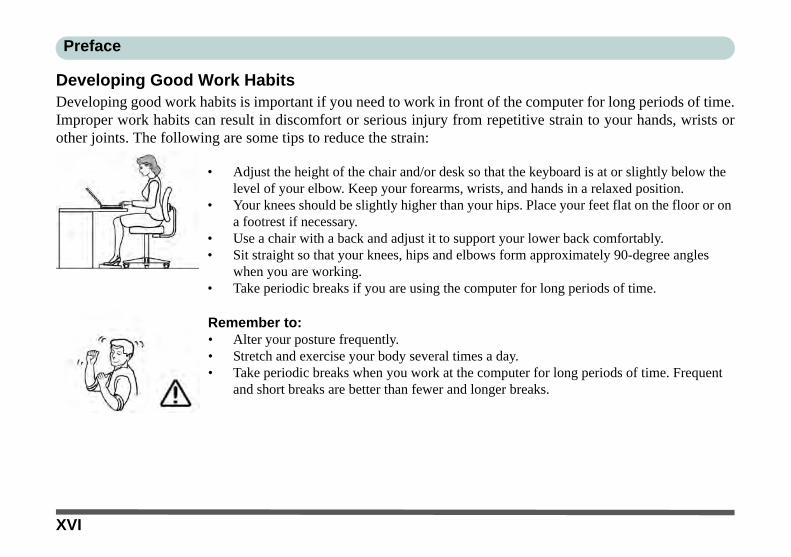
Developing Good Work HabitsDeveloping good work habits is important if you need to work in front of the computer for long periods of time.Improper work habits can result in discomfort or serious injury from repetitive strain to your hands, wrists orother joints. The following are some tips to reduce the strain:
• Adjust the height of the chair and/or desk so that the keyboard is at or slightly below the level of your elbow. Keep your forearms, wrists, and hands in a relaxed position.
• Your knees should be slightly higher than your hips. Place your feet flat on the floor or on a footrest if necessary.
• Use a chair with a back and adjust it to support your lower back comfortably.• Sit straight so that your knees, hips and elbows form approximately 90-degree angles
when you are working.• Take periodic breaks if you are using the computer for long periods of time.
Remember to:• Alter your posture frequently.• Stretch and exercise your body several times a day.• Take periodic breaks when you work at the computer for long periods of time. Frequent
and short breaks are better than fewer and longer breaks.
XVI
Preface
LightingProper lighting and comfortable display viewing angle can reduce eye strain and muscle fatigue in your neck andshoulders.
• Position the display to avoid glare or reflections from overhead lighting or outside sources of light.• Keep the display screen clean and set the brightness and contrast to levels that allow you to see the screen clearly.• Position the display directly in front of you at a comfortable viewing distance.• Adjust the display-viewing angle to find the best position.
LCD Screen CareTo prevent image persistence on LCD monitors (caused by the continuous display of graphics on the screen foran extended period of time) take the following precautions:
• Set the Windows Power Plans to turn the screen off after a few minutes of screen idle time.• Use a rotating, moving or blank screen saver (this prevents an image from being displayed too long).• Rotate desktop background images every few days.• Turn the monitor off when the system is not in use.
LCD Electro-Plated LogosNote that in computers featuring a raised LCD electro-plated logo, the logo is covered by a protective adhesive.Due to general wear and tear, this adhesive may deteriorate over time and the exposed logo may develop sharpedges. Be careful when handling the computer in this case, and avoid touching the raised LCD electro-platedlogo. Avoid placing any other items in the carrying bag which may rub against the top of the computer duringtransport. If any such wear and tear develops contact your distributor/supplier.
XVII

Preface
XVIII

Preface
ContentsNotice .............................................................................................................................................................IErP Off Mode Power Consumption Statement: ........................................................................................... IIFCC Statement ............................................................................................................................................IVFCC RF Radiation Exposure Statement: .....................................................................................................VInstructions for Care and Operation ......................................................................................................... VIIServicing .....................................................................................................................................................IXPower Safety ................................................................................................................................................XPolymer Battery Precautions ......................................................................................................................XIGeneral Battery Precautions ..................................................................................................................... XIICleaning ...................................................................................................................................................XIIITravel Considerations ..............................................................................................................................XIII
Quick Start GuideOverview ....................................................................................................................................................1-1Advanced Users .........................................................................................................................................1-2Beginners and Not-So-Advanced Users ....................................................................................................1-2Warning Boxes ..........................................................................................................................................1-2Not Included ..............................................................................................................................................1-3System Startup ...........................................................................................................................................1-4System Software ........................................................................................................................................1-5System Map: LCD Panel Open ..................................................................................................................1-6
XIX

Preface
LED Indicators ...........................................................................................................................................1-7Keyboard ....................................................................................................................................................1-8Keyboard Shortcuts ...................................................................................................................................1-9Keyboard Application Settings ................................................................................................................1-10Function/Hot Key Indicators ...................................................................................................................1-11Control Center .........................................................................................................................................1-12System Map: Front & Docked Views ......................................................................................................1-13System Map: Left View ...........................................................................................................................1-14System Map: Right & Rear Views ..........................................................................................................1-15System Map: Bottom View .....................................................................................................................1-173G/4G Module USIM Card Installation ..................................................................................................1-18Inserting the Battery ................................................................................................................................1-19Docking Port ............................................................................................................................................1-20Windows 10 Start Menu ..........................................................................................................................1-21Right-Clicking the Windows Logo In Start Menu ..................................................................................1-22Start Menu Apps & Tiles .........................................................................................................................1-23Windows 10 Control Panel ......................................................................................................................1-25Settings ....................................................................................................................................................1-26Windows 10 Taskbar ...............................................................................................................................1-27Action Center ...........................................................................................................................................1-28Video Features .........................................................................................................................................1-29Power Options .........................................................................................................................................1-33
XX

Preface
Features & ComponentsOverview ....................................................................................................................................................2-1Hard Disk Drive/Solid State Drive ............................................................................................................2-2Optical (CD/DVD) Device ........................................................................................................................2-3Loading Discs ............................................................................................................................................2-3Handling CDs or DVDs .............................................................................................................................2-4DVD Regional Codes ................................................................................................................................2-5Multi-In-1 Card Reader .............................................................................................................................2-6ExpressCard Slot .......................................................................................................................................2-7Inserting and Removing ExpressCards ......................................................................................................2-7Smart Card Reader .....................................................................................................................................2-7Touchpad and Buttons/Mouse ...................................................................................................................2-8Touchpad Sensitivity .................................................................................................................................2-9Touchpad Configuration ............................................................................................................................2-9Gestures and Device Settings ..................................................................................................................2-10Audio Features .........................................................................................................................................2-16Setup for Audio Recording ......................................................................................................................2-17
Power ManagementOverview ....................................................................................................................................................3-1The Power Sources ....................................................................................................................................3-2AC/DC Adapter .........................................................................................................................................3-2
XXI

Preface
Battery ........................................................................................................................................................3-2Turning On the Computer ..........................................................................................................................3-3Shutting the Computer Down ....................................................................................................................3-4Power Plans ...............................................................................................................................................3-5Power-Saving States ..................................................................................................................................3-7Sleep ..........................................................................................................................................................3-7Hibernate ....................................................................................................................................................3-8Shut down ..................................................................................................................................................3-8Configuring the Power Buttons .................................................................................................................3-9Resuming Operation ................................................................................................................................3-11Settings Menu Power Controls ................................................................................................................3-13Battery Information .................................................................................................................................3-16Battery Power ..........................................................................................................................................3-16Power Slider Settings ...............................................................................................................................3-17Conserving Battery Power .......................................................................................................................3-18Battery Life ..............................................................................................................................................3-19New Battery .............................................................................................................................................3-19Recharging the Battery with the AC/DC Adapter ...................................................................................3-19Proper handling of the Battery Pack ........................................................................................................3-20Battery FAQ .............................................................................................................................................3-21Removing the Battery ..............................................................................................................................3-25Inserting the Battery ................................................................................................................................3-26
XXII

Preface
Drivers & UtilitiesWhat to Install ............................................................................................................................................4-1Module Driver Installation ........................................................................................................................4-1Driver Installation ......................................................................................................................................4-2Updating/Reinstalling Individual Drivers ..................................................................................................4-5User Account Control ................................................................................................................................4-6Windows Security Message .......................................................................................................................4-6New Hardware Found ................................................................................................................................4-6Driver Installation Procedure .....................................................................................................................4-7Chipset .......................................................................................................................................................4-7Video (VGA) .............................................................................................................................................4-7LAN ...........................................................................................................................................................4-7CardReader ................................................................................................................................................4-7Touchpad ...................................................................................................................................................4-7Control Center ...........................................................................................................................................4-8Airplane .....................................................................................................................................................4-8MEI Driver .................................................................................................................................................4-8Audio .........................................................................................................................................................4-8Optional Drivers ......................................................................................................................................4-10
XXIII
Preface
BIOS UtilitiesOverview ....................................................................................................................................................5-1The Setup Utility ........................................................................................................................................5-2Failing the POST .......................................................................................................................................5-3Fatal Errors ................................................................................................................................................5-3Non-Fatal Errors ........................................................................................................................................5-3Setup Screens .............................................................................................................................................5-4Main Menu .................................................................................................................................................5-5System Time & Date (Main Menu) ...........................................................................................................5-5SATA Port # (Main Menu) ........................................................................................................................5-6OffBoard SATA/NVme Controller Configuration (Main Menu) .............................................................5-6CPU/ ME FW Version / System/ Extended Memory: (Main Menu) ........................................................5-6MB Series / BIOS Revision / KBC/EC firmware Revision / Mac Address (Main Menu) ........................5-6Advanced Menu .........................................................................................................................................5-7Advanced Chipset Control (Advanced Menu) ..........................................................................................5-8FlexiCharger (Advanced Menu > Advanced Chipset Control) .................................................................5-9Software Guard Extensions (Advanced Menu > Advanced Chipset Control) ........................................5-10VT-d (Advanced Menu > Advanced Chipset Control) ............................................................................5-10Fast Boot(Advanced Menu > Advanced Chipset Control) ......................................................................5-10Intel Virtualization Technology (Advanced Menu > Advanced Chipset Control) ..................................5-10SATA Mode (Advanced Menu) ..............................................................................................................5-11Power On Boot Beep (Advanced Menu) .................................................................................................5-11
XXIV

Preface
Battery Low Alarm Beep (Advanced Menu) ...........................................................................................5-11Security Menu ..........................................................................................................................................5-12Set Supervisor Password (Security Menu) ..............................................................................................5-12Set User Password (Security Menu) ........................................................................................................5-13Password on boot (Security Menu) ..........................................................................................................5-13Secure Boot Support (Security Menu) .....................................................................................................5-14TPM Configuration (Security Menu) ......................................................................................................5-15Boot Menu ...............................................................................................................................................5-16Boot Option Priorities (Boot Menu) ........................................................................................................5-17UEFI Boot (Boot Menu > UEFI Setting) ................................................................................................5-17Exit Menu ................................................................................................................................................5-18
Modules & OptionsOverview ....................................................................................................................................................6-1Wireless LAN Module ...............................................................................................................................6-33rd Party 802.11b/g/n Driver Installation ..................................................................................................6-4Intel® WLAN Driver Installation ..............................................................................................................6-4WLAN Configuration in Windows ...........................................................................................................6-5Bluetooth Combo Module .........................................................................................................................6-83rd Party Bluetooth (V4.0) Combo Driver Installation .............................................................................6-9Intel Bluetooth Combo Driver Installation ................................................................................................6-9Bluetooth Configuration in Windows ......................................................................................................6-10
XXV

Preface
To Make your Computer Discoverable to Bluetooth Devices .................................................................6-13Fingerprint Reader Module ......................................................................................................................6-14Fingerprint Reader Driver Installation .....................................................................................................6-15Fingerprint Module Configuration ..........................................................................................................6-16Intel® Software Guard Extensions ..........................................................................................................6-18Intel SGX Driver Installation ...................................................................................................................6-18Intel® Rapid Storage Technology ...........................................................................................................6-19IRST Driver Installation ..........................................................................................................................6-19Intel® vPro™ Technology ......................................................................................................................6-20Accessing the Intel Management Engine ................................................................................................6-20PC Camera Module ..................................................................................................................................6-23Camera App .............................................................................................................................................6-24Taking Pictures/Capturing Video ............................................................................................................6-27Trusted Platform Module .........................................................................................................................6-29Enabling & Managing TPM ....................................................................................................................6-30TPM Management in Windows ...............................................................................................................6-31TPM Actions ............................................................................................................................................6-333G/4G Module .........................................................................................................................................6-353G/4G Configuration ...............................................................................................................................6-38
XXVI

Preface
TroubleshootingOverview ....................................................................................................................................................7-1Basic Hints and Tips ..................................................................................................................................7-2Backup and General Maintenance .............................................................................................................7-3Viruses .......................................................................................................................................................7-4Upgrading and Adding New Hardware/Software ......................................................................................7-5Problems and Possible Solutions ...............................................................................................................7-7
Interface (Ports & Jacks)Overview ...................................................................................................................................................A-1Notebook Ports and Jacks .........................................................................................................................A-2
Control CenterOverview ...................................................................................................................................................B-1
Video Driver ControlsVideo Driver Installation ..........................................................................................................................C-1Dynamic Video Memory Technology ......................................................................................................C-1Intel® HD Graphics Control Panel ...........................................................................................................C-2Display Devices & Options ....................................................................................................................C-15Attaching Other Displays .......................................................................................................................C-16Configure Other Displays Using Project ................................................................................................C-18
XXVII

Preface
You can configure attached displays from Project. ................................................................................C-18Configuring an External Display In Windows .......................................................................................C-19HDMI Audio Configuration ...................................................................................................................C-20Wireless Display .....................................................................................................................................C-23Wireless Display Configuration .............................................................................................................C-24
SpecificationsCore Logic ................................................................................................................................................D-2Display ......................................................................................................................................................D-2Memory .....................................................................................................................................................D-2Storage ......................................................................................................................................................D-2Audio ........................................................................................................................................................D-2Keyboard & Pointing Device ....................................................................................................................D-2Interface ....................................................................................................................................................D-2Card Reader ..............................................................................................................................................D-3Slot ............................................................................................................................................................D-3Communication .........................................................................................................................................D-3Power ........................................................................................................................................................D-3Security .....................................................................................................................................................D-3Design Features ........................................................................................................................................D-4Operating System ......................................................................................................................................D-4BIOS .........................................................................................................................................................D-4
XXVIII

Preface
Power Management ..................................................................................................................................D-4Indicators ..................................................................................................................................................D-4Environmental Spec ..................................................................................................................................D-4Dimensions & Weight ..............................................................................................................................D-4
Docking Station GuideOverview ................................................................................................................................................... E-1Compatibility ............................................................................................................................................ E-1Computer and Docking Station ................................................................................................................ E-2Docked System Power .............................................................................................................................. E-2System Map: Front View .......................................................................................................................... E-3System Map: Rear View ........................................................................................................................... E-4Power Button LED & Lock Switch LED Indicator .................................................................................. E-5System Map: Left & Right Views ............................................................................................................ E-6Cold Docking the Computer to the Docking Station ................................................................................ E-7Cold Undocking the Computer from the Docking Station ..................................................................... E-10Hot Docking the Computer to the Docking Station ................................................................................ E-11Hot Undocking the Computer from the Docking Station ....................................................................... E-14Power Button Configuration ................................................................................................................... E-17Docking Station Ports & Jacks ............................................................................................................... E-18Multiple Displays .................................................................................................................................... E-23BIOS Controls - USB ports, Card Reader, Smart Card & ExpressCard ................................................ E-23
XXIX

Preface
One Button Hard Disk Backup ............................................................................................................... E-24Backup Procedure ................................................................................................................................... E-25System Image Backup ............................................................................................................................ E-27System Image Recovery ......................................................................................................................... E-29File History Backup ................................................................................................................................ E-31Restoring Files from File History Backup .............................................................................................. E-35Specifications .......................................................................................................................................... E-38Storage .................................................................................................................................................... E-38Interface and Ports .................................................................................................................................. E-38Buttons & Switches ................................................................................................................................ E-38Power ...................................................................................................................................................... E-38Security ................................................................................................................................................... E-38LED Indicators ........................................................................................................................................ E-38Environmental Spec ................................................................................................................................ E-38Dimensions & Weight ............................................................................................................................ E-38
XXX

Quick Start Guide 1
Chapter 1: Quick Start GuideOverviewThis Quick Start Guide is a brief introduction to the basic features of your computer, to navigating around thecomputer and to getting your system started. The remainder of the manual covers the following:
• Chapter 2 A guide to using some of the main features of the computer e.g. the storage devices (hard disk, card reader & ExpressCard), Touchpad & Mouse and Audio.
• Chapter 3 The computer’s power saving options.• Chapter 4 The installation of the drivers and utilities essential to the operation or improvement of some of the
computer’s subsystems.• Chapter 5 An outline of the computer’s built-in software or BIOS (Basic Input Output System).• Chapter 6 A quick guide to the computer’s PC Camera, Wireless LAN, Fingerprint Reader, 3G/4G, Blue-
tooth, Trusted Platform (TPM) and Intel modules (some of which may be optional depending on your purchase configuration).
• Chapter 7 A troubleshooting guide.• Appendix A Definitions of the interface, ports/jacks which allow your computer to communicate with external
devices.• Appendix B Information on the Control Center.• Appendix C Information on the video driver controls.• Appendix D The computer’s specification.• Appendix E A guide to the Docking Station.
Overview 1 - 1
Quick Start Guide1
Advanced UsersIf you are an advanced user you may skip over most of this Quick Start Guide. However you may find it usefulto refer to “What to Install” on page 4 - 1 and “BIOS Utilities” on page 5 - 1 in the reminder of the User’sManual. You may also find the notes marked with a of interest to you.Beginners and Not-So-Advanced UsersIf you are new to computers (or do not have an advanced knowledge of them) thenthe information contained in the Quick Start Guide should be enough to get you upand running. Eventually you should try to look through all the documentation (moredetailed descriptions of the functions, setup and system controls are covered in theremainder of the User’s Manual), but do not worry if you do not understand every-thing the first time. Keep this manual nearby and refer to it to learn as you go. Youmay find it useful to refer to the notes marked with a as indicated in the margin.For a more detailed description of any of the interface ports and jacks see “Interface(Ports & Jacks)” on page A - 1.
Warning BoxesNo matter what your level please pay careful attention to the warning and safety information indicated by the symbol. Also please note the safety and handling instructions as indicated in the Preface.
Notes
Check the light coloredboxes with the markabove to find detailedinformation about thecomputer’s features.
1 - 2 Overview

Quick Start Guide 1
Not IncludedOperating Systems (e.g. Windows 10) and applications (e.g. word processing, spreadsheet and database pro-grams) have their own manuals, so please consult the appropriate manuals.Drivers
If you are installing new system software, or are re-configuring your computer for a different system, you will need to installthe drivers listed in “Drivers & Utilities” on page 4 - 1. Drivers are programs which act as an interface between the com-puter and a hardware component e.g. a wireless network module. It is very important that you install the drivers in the orderlisted. You will be unable to use most advanced controls until the necessary drivers and utilities are properly installed. Ifyour system hasn’t been properly configured (your service representative may have already done that for you); refer toChapter 4 for installation instructions.
Ports and Jacks
See “Notebook Ports and Jacks” on page A - 2 for a description of the interface (ports & jacks) which allow your com-puter to communicate with external devices, connect to the internet etc.
Overview 1 - 3

Quick Start Guide1
System Startup1. Remove all packing materials, and place the computer on a stable surface.2. Securely attach any peripherals you want to use with the notebook (e.g. keyboard and mouse) to their ports.3. When first setting up the computer use the following procedure (as to safeguard the computer during
shipping, the battery will be locked to not power the system until first connected to the AC/DC adapter andinitially set up as below):
• Attach the AC/DC adapter cord to the DC-In jack on the left of the computer, then plug the AC power cord into an outlet, and connect the AC power cord to the AC/DC adapter and leave it there for 6 seconds or longer.
• Remove the adapter cord from the computer’s DC-In jack, and then plug it back in again; the battery will now be unlocked.
4. Use one hand to raise the lid/LCD to a comfortable viewing angle (do not exceed 180 degrees - or 130 degrees if the system is docked to the docking station or has a 9 cell battery inserted); use the other hand to support the base of the computer (Note: Never lift the computer by the lid/LCD).
180°
Shutdown
Note that you should always shut your computer down by choosing the Shut Down com-mand in Windows (see page 1 - 33). This will help prevent hard disk or system problems.
LCD Open Angle
The LCD may be opened to 180 de-grees, however if the 9 cell battery isinserted, or the computer is dockedto the docking station, the angleshould not exceed 130 degrees.
Figure 1 - 1 Opening the Lid/LCD
1 - 4 System Startup

Quick Start Guide 1
System SoftwareYour computer may already come with system software pre-installed. Where this is not the case, or where youare re-configuring your computer for a different system, you will find the Windows 10 (64-bit) operating systemis supported.Windows OS
Note that the information included on the following pages is for Windows 10 only.
In order to run Windows 10 (64-bit) your computer requires a minimum 2GB of system memory (RAM).
System Startup 1 - 5

Quick Start Guide1
System Map: LCD Panel OpenFigure 1 - 2LCD Panel Open
1. Built-In PC Camera (Optional)
2. PC Camera LED3. Built-In Microphone4. LCD5. Power Button6. Keyboard7. Touchpad &
Buttons8. Fingerprint Reader
Sensor9. LED Indicators
Note that the Touchpad andButtons valid operational areais that indicated within the reddotted lines above.
7
2
6
1
9
5
Wireless Device
Operation Aboard Aircraft
The use of any portableelectronic transmissiondevices aboard aircraft isusually prohibited. Makesure the module(s) areOFF if you are using thecomputer aboard aircraft.
Use Fn + F11 AirplaneMode key combination totoggle Airplane Mode On/Off, and check the LED in-dicator for the power sta-tus (see Table 1 - 1, onpage 1 - 7).
7
8 9
3
4
3
1 - 6 System Map: LCD Panel Open

Quick Start Guide 1
LED IndicatorsThe LED indicators on the computer display helpful information about the current status of the computer.
Table 1 - 1 - LED Indicators
Icon Color Description Icon Color Description
Orange DC Power is Plugged In White Power Button
Blinking Orange
The Powered USB Port is On* (System Off) White Hard Disk Activity
The Camera is in Use (System On)
WhiteAirplane Mode is ON (the WLAN, Bluetooth & 3G/4G
Modules are OFF)
White The Computer is On White Number Lock is Activated
Blinking White The Computer is in Sleep Mode White Caps Lock is Activated
Orange The Battery is Charging White Scroll Lock is Activated
White The Battery is Fully Charged *Note: The powered USB 3.0 port (see Figure 1 - 7 on page 1 -14) may be toggled on /off by means of the Fn + Power Buttonkey combination. When the powered USB port is on it will supplypower (for charging devices only, not for operating devices)when the system is off but still powered by the AC/DC adapterplugged into a working outlet, or powered by the battery with a ca-pacity level above 20% (this may not work with certain devices).
Blinking OrangeThe Battery has Reached Critically Low
Power Status
LED Indicators 1 - 7

Quick Start Guide1
KeyboardThe keyboard has an embedded numerical keypad for easy numeric data input, andfeatures function keys to allow you to change operational features instantly. SeeTable 1 - 3, on page 1 - 11 for full function key combination details.
Figure 1 - 3 - Keyboard
Other Keyboards
If your keyboard isdamaged or you justwant to make achange, you can useany standard USB key-board. The system willdetect and enable itautomatically. Howev-er special functions/hot-keys unique to thesystem’s regular key-board may not work.
NumLk & ScrLk
Hold down the Fn Keyand either NumLk orScrLk to enable num-ber or scroll lock, andcheck the LED indica-tor for status.
Numerical
Play/Pause Key
Function Keys
ScrLk & NumLk Keys
Fn KeyKeypad
Windows Logo Key Menu/Application Key
Special Characters
Some software applications allow the number-keys to be used with Alt to produce special characters.These special characters can only be produced by using the numeric keypad. Regular number keys (inthe upper row of the keyboard) will not work. Make sure that NumLk is on.
1 - 8 Keyboard

Quick Start Guide 1
Keyboard ShortcutsThe following Windows Logo Key (Winkey) keyboard shortcuts are useful for navi-gation/operation in Windows 10.Table 1 - 2 - Keyboard Shortcuts
Windows Logo Key +
Description
Tap Winkey Toggle the Start menu
A Open the Action Center
B Select the Taskbar Notification Area
C Launch Cortana (in listening mode)
D Toggle the Desktop
E Launch File Explorer (Quick Access tab)
+ Number (1, 2, etc) Launch an application from the taskbar (numbered from left to right)
Windows Logo
Keyboard Shortcut
Use the Windows logokey + D key com-bination to switch be-tween the Start screenand Windows Desktop.
Menu/Application Keyboard Shortcut
When the Desktop appis running you can usethe Menu/Applicationkey on the key-board to display thecontext menu as per amouse right-click.
Keyboard 1 - 9

Quick Start Guide1
Keyboard Application Settings (Factory Option)If your computer includes an illuminated keyboard (Factory Option), you will need to install the keyboard Con-trol Center application driver (see “Control Center” on page 4 - 8) and you can then select the type of keyboardas appropriate for your model’s configuration (you can only select keyboards supported by your system). Afterthe driver has been installed, and the system restarts, the control panel below will pop-up to allow you to selectthe illuminated white keyboard for your system. Click Save to retain the setting chosen.
If you wish to change the setting at any time then right-click on the Control Center icon and select Key-board Settings to return to the keyboard select control panel.
Figure 1 - 4 - Keyboard Settings for Illuminated Keyboard Option
Right-click and select Keyboard Setting
1 - 10 Keyboard Application Settings

Quick Start Guide 1
Function/Hot Key Indicators
Table 1 - 3 - Function Keys & Visual Indicators
Keys Function Keys Function
Fn + Play/Pause (in Audio/Video Programs) Fn + PC Camera Power Toggle
Fn + TouchPad Toggle Fn + Airplane Mode Toggle
Fn + Turn LCD Backlight Off
(Press a key to or use TouchPad to turn on) Fn + Sleep Toggle
Fn + Mute Toggle Fn + NumLk Number Lock Toggle
Fn +
Backlight Keyboard Level Adjust (Illuminated
Keyboards Designs Only)
Fn + ScrLk Scroll Lock Toggle
Fn + Volume Decrease/Increase Caps Lock Caps Lock Toggle
Fn + Display Switch Menu Fn + Fan Control Toggle between
Automatic Fan Control / Full Power
Fn + Brightness Decrease/Increase Fn + Control Center Toggle (see over)
Function/Hot Key Indicators 1 - 11

Quick Start Guide1
Control CenterWhen in the Windows Desktop application (not in the Start screen) press the Fn + Esc key combination, ordouble-click the icon in the notification area of the taskbar to toggle the Control Center on/off. The Con-trol Center gives quick access to frequently used controls and enables you to quickly turn the camera/TouchPad on/off.
Figure 1 - 5 - Control Center
Control Center Access
To run theControl Cen-ter press theFn + Esc keycombination,or double-click the icon
in the noti-fication areaof the taskbar.
Close the Control Center by clickingthe close icon in the top right of thepanel (move the cursor onto the topright corner of the panel to highlight it).
1 - 12 Control Center

Quick Start Guide 1
System Map: Front & Docked Views Figure 1 - 6Front & Docked
Views (with Optional
Docking Station)
1. LED Indicators2. Docking Station
(Optional)
Docking
If your purchase includesthe docking station, openthe docking port cover latchand align the computer withthe placeholder on the dock-ing station (see the accom-panying docking station forfull details of the dockingprocedure).
2
1
2
2
Docking Port Cover
Make sure you keep the docking cover closed when the computer is not docked in the sta-tion. This will help prevent foreign objects and/or dust getting in to the contact area,
If the docking station is included in your purchase configuration, make sure you open thecover of the docking port before connecting the computer to the station, as failure to do somay result in irreparable damage to the connector on the docking station.
System Map: Front & Docked Views 1 - 13
Quick Start Guide1
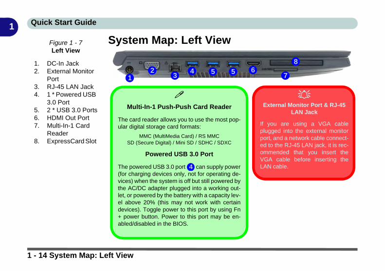
System Map: Left ViewFigure 1 - 7Left View
1. DC-In Jack2. External Monitor
Port3. RJ-45 LAN Jack4. 1 * Powered USB
3.0 Port5. 2 * USB 3.0 Ports6. HDMI Out Port7. Multi-In-1 Card
Reader8. ExpressCard Slot
2 541 3
Multi-In-1 Push-Push Card Reader
The card reader allows you to use the most pop-ular digital storage card formats:
MMC (MultiMedia Card) / RS MMCSD (Secure Digital) / Mini SD / SDHC / SDXC
Powered USB 3.0 Port
The powered USB 3.0 port can supply power(for charging devices only, not for operating de-vices) when the system is off but still powered bythe AC/DC adapter plugged into a working out-let, or powered by the battery with a capacity lev-el above 20% (this may not work with certaindevices). Toggle power to this port by using Fn+ power button. Power to this port may be en-abled/disabled in the BIOS.
4
67
8
External Monitor Port & RJ-45
LAN Jack
If you are using a VGA cableplugged into the external monitorport, and a network cable connect-ed to the RJ-45 LAN jack, it is rec-ommended that you insert theVGA cable before inserting theLAN cable.
5
1 - 14 System Map: Left View

Quick Start Guide 1
System Map: Right & Rear Views Figure 1 - 8Right & Rear Views
1. 1 * USB 2.0 Port2. Microphone-In
Jack3. 2-in-1 Audio Jack
(Headphone Out/S/PDIF Out Jack)
4. Optical Device Drive Bay (for DVD Device)
5. Security Lock Slot6. Smart Card
Reader7. Battery
1 2 34 5
6
7
USB 2.0 or 3.0 Ports
USB 3.0 ports are denoted by their blue color; USB 2.0 ports are colored black.
Battery Information
Always completely discharge, then fully charge, a new battery before using it. Completelydischarge and charge the battery at least once every 30 days or after about 20 partial dis-charges.
System Map: Right & Rear Views 1 - 15

Quick Start Guide1
Disk Eject Warning
Don’t try to eject a CD/DVD while the system is ac-cessing it. This may cause the system to “crash”. Stopthe disk first then eject it, or press the stop buttontwice.
CD/DVD Emergency Eject
If you need to manually eject a CD/DVD (e.g. due toan unexpected power interruption) you may push theend of a straightened paper clip into the emergencyeject hole. Do not use a sharpened pencil or any ob-ject that may break and become lodged in the hole.Don’t try to remove a floppy disk/CD/DVD while thesystem is accessing it. This may cause the system to“crash”.
Changing DVD Regional Codes
Go to the Control Panel and double-click Device Man-ager (Hardware and Sound), then click the + next toDVD/CD-ROM drives. Double-click on the DVD-ROMdevice to bring up the Properties dialog box, and se-lect the DVD Region (tab) to bring up the control pan-el to allow you to adjust the regional code).
DVD region detection is device dependent, not OS-dependent. You can select your module’s regioncode 5 times. The fifth selection is permanent. Thiscannot be altered even if you change your operatingsystem or you use the module in another computer(see “DVD Regional Codes” on page 2 - 5).
1 - 16 System Map: Right & Rear Views
Quick Start Guide 1
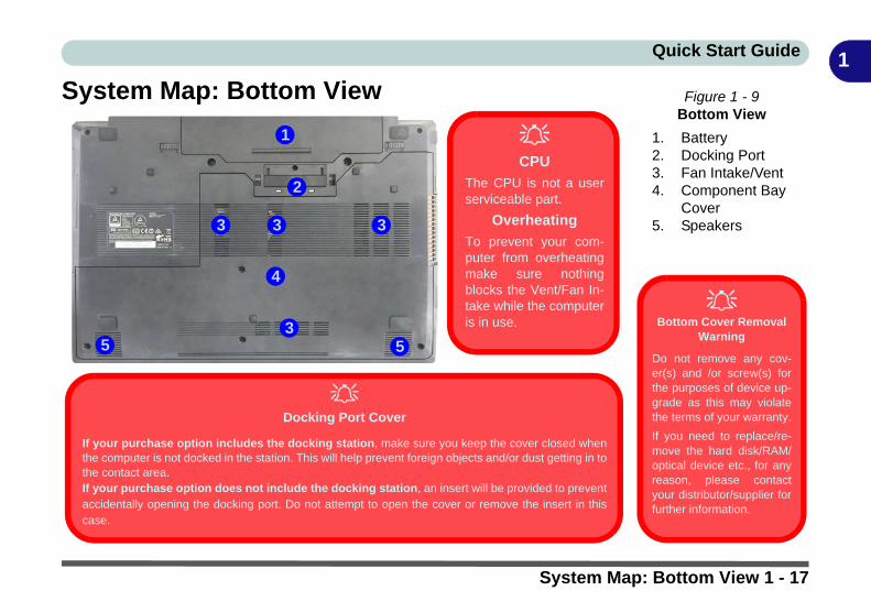
System Map: Bottom View Figure 1 - 9Bottom View
1. Battery2. Docking Port3. Fan Intake/Vent4. Component Bay
Cover5. Speakers
Bottom Cover Removal
Warning
Do not remove any cov-er(s) and /or screw(s) forthe purposes of device up-grade as this may violatethe terms of your warranty.
If you need to replace/re-move the hard disk/RAM/optical device etc., for anyreason, please contactyour distributor/supplier forfurther information.
2
1
4
3
CPU
The CPU is not a userserviceable part.
Overheating
To prevent your com-puter from overheatingmake sure nothingblocks the Vent/Fan In-take while the computeris in use.
553
3 3
Docking Port Cover
If your purchase option includes the docking station, make sure you keep the cover closed whenthe computer is not docked in the station. This will help prevent foreign objects and/or dust getting in tothe contact area.If your purchase option does not include the docking station, an insert will be provided to preventaccidentally opening the docking port. Do not attempt to open the cover or remove the insert in thiscase.
System Map: Bottom View 1 - 17

Quick Start Guide1
3G/4G Module USIM Card InstallationIf you have included an optional 3G/4G module in your purchase option, follow the instructions below to installthe USIM card (which will be provided by your service provider).
1. Turn off the computer, and turn it over and then remove the battery (slide latch in the direction indicated below, then slide hold latch in place and slide the battery out in the direction of arrow ).
2. Insert the USIM card into the slot at the rear of the battery compartment, as illustrated below, until it clicks fully into position, and then replace the battery (see over).
Figure 1 - 10 - Battery Removal & USIM Card Insertion
12 3
4
USIM Card Orientation
Note that the USIM card’s read-able side (with the gold-coloredcontacts) should face down as il-lustrated.
123
123
4
6 Cell Battery
9 Cell Battery
1 - 18 3G/4G Module USIM Card Installation

Quick Start Guide 1
Inserting the Battery1. Turn the computer off, and turn it over.2. Slide the battery into the compartment in the direction of the arrow .3. Slide the latches and in the direction of the arrows to lock the battery.
Figure 1 - 11 - Battery Insertion
12 3
1
2 33
1
2
6 Cell Battery 9 Cell Battery
Inserting the Battery 1 - 19

Quick Start Guide1
Docking PortFollow the instructions below before connecting the computer to the docking station, if included in your pur-chase configuration. Failure to open the cover of the docking port before connecting the computer to the dockingstation may result in irreparable damage to the connector on the docking station.
1. Turn the computer over.2. Slide the docking port cover latch in the direction of the arrow at point to open the cover.3. After disconnecting the computer from the docking station, slide the docking port cover latch in the direction of
the arrow at point .
1
2
Docking Port
Cover
Make sure you keepthe cover closedwhen the computer isnot docked in the sta-tion. This will helpprevent foreign ob-jects and/or dust get-ting in to the contactarea.
1
2
Figure 1 - 12 - Opening and Closing the Docking Port
1 - 20 Docking Port

Quick Start Guide 1
Windows 10 Start MenuMost of the apps, control panels, utilities and programs within Windows 10 can be accessed from the StartMenu by clicking the icon in the taskbar in the lower left corner of the screen (or by pressing the WindowsLogo Key on the keyboard).
Figure 1 - 13 - Windows Start Menu
Desktop
Windows Screens
Note that the Win-dows screens on thefollowing pages areincluded as a basicguide and introduc-tion to navigatingaround Windows 10.
However note thatthese screens are al-ways subject tochange, upgrade andredesign. Check theMicrosoft website fordetails.
Windows 10 Start Menu 1 - 21

Quick Start Guide1
Right-Clicking the Windows Logo In Start MenuRight-click the Start Menu icon (or use the Windows Logo Key + X key combination) to bring up anadvanced Context Menu of useful features such as Apps and Features, Power Options, Task Manager, Search,File Explorer, Device Manager, Computer Management and Network Connections etc.Figure 1 - 14 - Right-Click Windows Logo in Start Menu
Right-Click Icon
1 - 22 Windows 10 Start Menu

Quick Start Guide 1
Start Menu Apps & TilesThe Windows 10 Start Menu will contain a number of apps, and many more will be installed as you add moreapplications etc. Not all of these apps can fit on the screen so may need click and drag the handles at the edge ofthe screen to expand the menu in order to view all the apps (you can use the scroll bar to move up and down thescreen).Figure 1 - 15 - Expanding the Start Menu
Windows 10 Start Menu 1 - 23

Quick Start Guide1
Pining/Unpinning Apps & Programs to/from the Start MenuTo make things easy to find you can add and remove tiles for apps and programs to the Start Menu. Right-Clickon a program’s icon and select Pin to Start from the drop-down menu. To remove an app or program from theStart Menu right-click the icon and select Unpin from Start. You can use the same method to pin apps/pro-grams to/from the taskbar (select pin to taskbar/unpin this program from the taskbar).Figure 1 - 16 - Pin to Start/Unpin from Start
1 - 24 Windows 10 Start Menu
Quick Start Guide 1
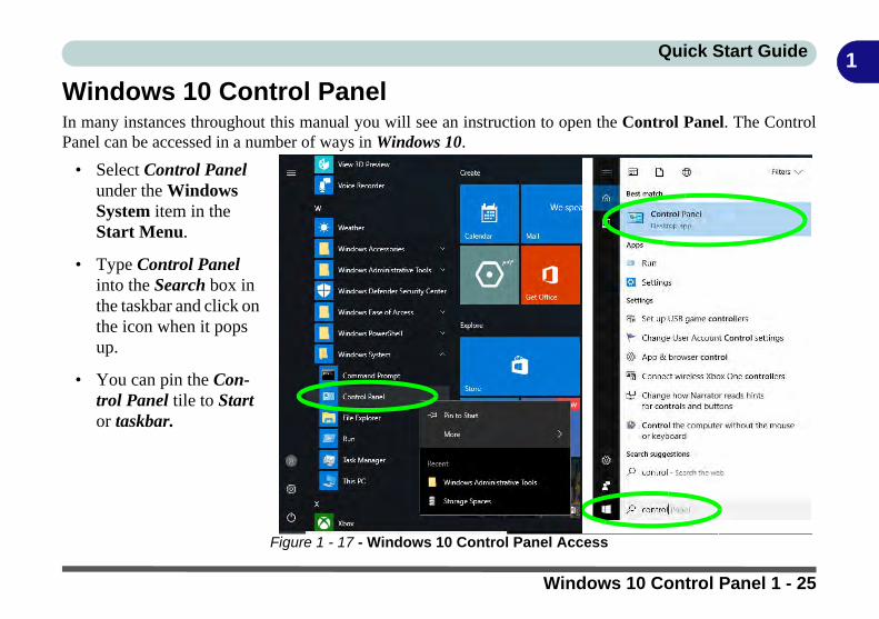
Windows 10 Control PanelIn many instances throughout this manual you will see an instruction to open the Control Panel. The ControlPanel can be accessed in a number of ways in Windows 10.
Figure 1 - 17 - Windows 10 Control Panel Access
• Select Control Panel under the Windows System item in the Start Menu.
• Type Control Panel into the Search box in the taskbar and click on the icon when it pops up.
• You can pin the Con-trol Panel tile to Start or taskbar.
Windows 10 Control Panel 1 - 25
Quick Start Guide1
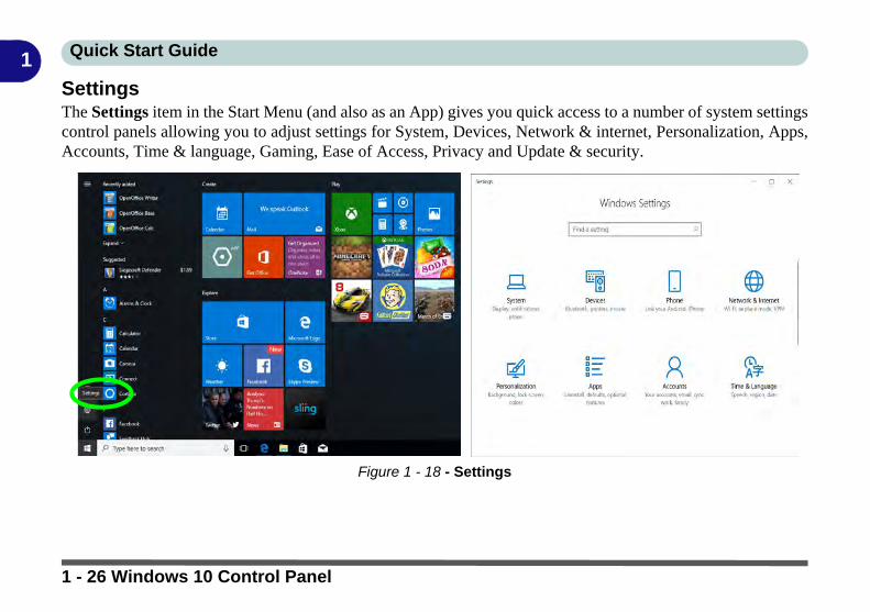
SettingsThe Settings item in the Start Menu (and also as an App) gives you quick access to a number of system settingscontrol panels allowing you to adjust settings for System, Devices, Network & internet, Personalization, Apps,Accounts, Time & language, Gaming, Ease of Access, Privacy and Update & security.Figure 1 - 18 - Settings
1 - 26 Windows 10 Control Panel

Quick Start Guide 1
Windows 10 TaskbarIn many instances throughout this manual you will see an instruction to access the notification area of the task-bar. The notification area of the taskbar in the bottom right of the screen. Some of the Control Panels and appli-cations referred to throughout the course of this manual can be accessed from here.Figure 1 - 19 - Taskbar
You can pin/unpin apps to/from the taskbar in much the same way as you can to the Start screen (see “Pining/Unpinning Apps & Programs to/from the Start Menu” on page 1 - 24).
Taskbar
Taskbar - Pinned Programs and Apps Notification Area
Windows 10 Control Panel 1 - 27

Quick Start Guide1
Action CenterThe Action Center appears as a vertical panel on the right side of the screen when you swipe in from the rightor click the button in the notification tray. This gives you access to commonly needed functions like Network,All Settings, Airplane Mode, and Project etc.Figure 1 - 20 - Action Center
1 - 28 Windows 10 Control Panel

Quick Start Guide 1
Video FeaturesYou can switch display devices, and configure display options, from the Display settings (click the Start Menuand click Settings > System or right-click the desktop and select Display settings) control panel. In Windows10 it is possible to quickly configure external displays from the Project menu (press the Windows logo key on your keyboard and the P key or Fn + F7).
To Configure Displays using Project
Figure 1 - 21 - Project (Devices)
1. Attach your display to the appropriate port, and turn it on.
2. Press the + P key combination.3. Click on any one of the options from
the menu to select PC screen only,Duplicate, Extend or Secondscreen only.
4. You can also click Connect to awireless display at the bottom of theProject screen and follow the stepsto connect to any wireless enableddisplay.
Video Features 1 - 29

Quick Start Guide1
To access the Display Settings:1. You can quickly adjust the display by right-clicking the desktop and selecting Display Settings.2. Adjust the settings for Brightness and color, Scale and layout, Resolution and Orientation from the menus.3. When and external display is attached you can arrange the display configuration from the Multiple Displaysmenu, and arrange the configuration from Select and rearrange displays.4. Click Apply to save any changes made.
Figure 1 - 22 - Display Settings
1 - 30 Video Features

Quick Start Guide 1
To access the Intel(R) HD Graphics Control Panel:1. Right-click the desktop and select Intel(R) Graphics Settings from the menu.OR2. Click the icon in the notification area of the Desktop taskbar and select Intel(R) Graphics Settings from themenu
Figure 1 - 23 - Intel Graphics Control Panel
Video Features 1 - 31

Quick Start Guide1
Minimum Screen Resolution Settings1. Windows 10 has minimum screen resolution requirements.2. Right-click a blank area of the Desktop and select Display Settings.3. Adjust the Resolution to make sure that it is at least 1024 * 768, although preferably 1366 * 768 or above.Figure 1 - 24 - Display (Resolution)
1 - 32 Video Features
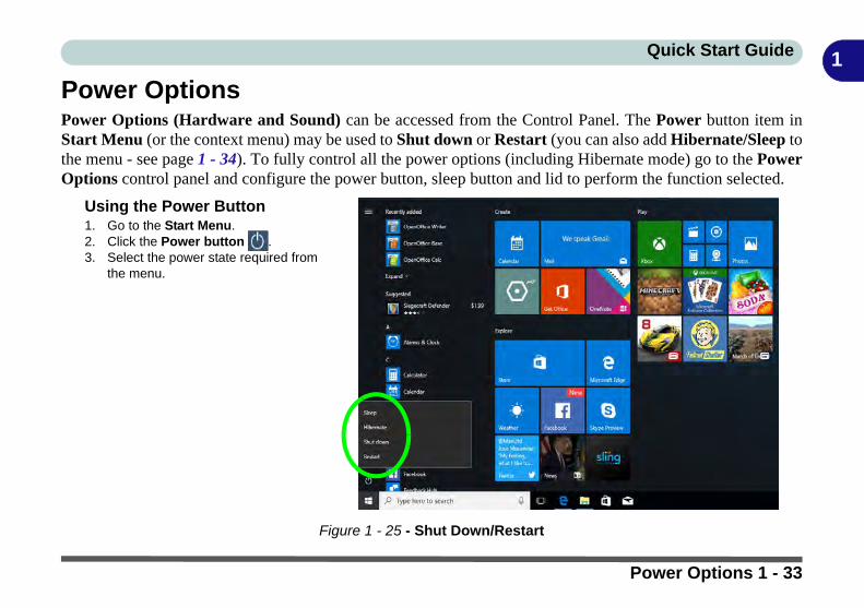
Quick Start Guide 1
Power OptionsPower Options (Hardware and Sound) can be accessed from the Control Panel. The Power button item inStart Menu (or the context menu) may be used to Shut down or Restart (you can also add Hibernate/Sleep tothe menu - see page 1 - 34). To fully control all the power options (including Hibernate mode) go to the PowerOptions control panel and configure the power button, sleep button and lid to perform the function selected.
Figure 1 - 25 - Shut Down/Restart
Using the Power Button1. Go to the Start Menu.2. Click the Power button .3. Select the power state required from
the menu.
Power Options 1 - 33
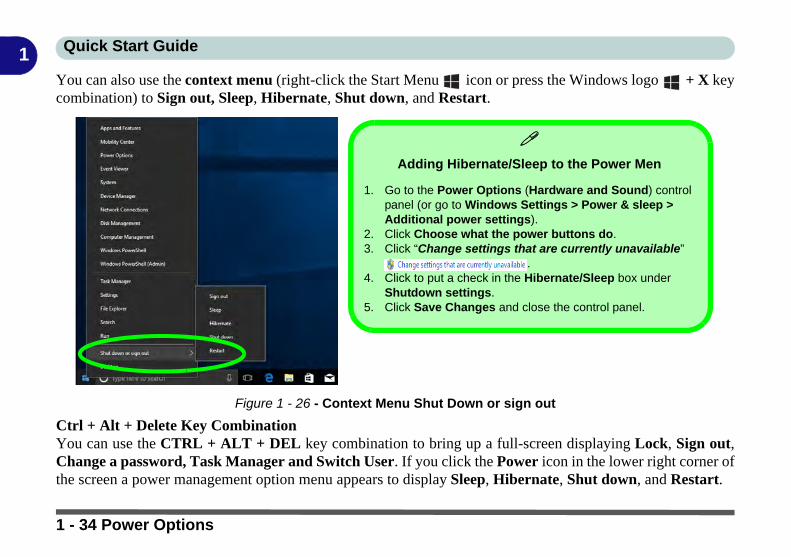
Quick Start Guide1
You can also use the context menu (right-click the Start Menu icon or press the Windows logo + X keycombination) to Sign out, Sleep, Hibernate, Shut down, and Restart.Figure 1 - 26 - Context Menu Shut Down or sign out
Ctrl + Alt + Delete Key CombinationYou can use the CTRL + ALT + DEL key combination to bring up a full-screen displaying Lock, Sign out,Change a password, Task Manager and Switch User. If you click the Power icon in the lower right corner ofthe screen a power management option menu appears to display Sleep, Hibernate, Shut down, and Restart.
Adding Hibernate/Sleep to the Power Men
1. Go to the Power Options (Hardware and Sound) control panel (or go to Windows Settings > Power & sleep > Additional power settings).
2. Click Choose what the power buttons do.3. Click “Change settings that are currently unavailable”
.4. Click to put a check in the Hibernate/Sleep box under
Shutdown settings.5. Click Save Changes and close the control panel.
1 - 34 Power Options

Features & Components
2
Chapter 2: Features & ComponentsOverviewRead this chapter to learn more about the following main features and componentsof the computer:
• Hard Disk Drive/Solid State Drive• Optical (CD/DVD) Device• Multi-In-1 Card Reader• ExpressCard Slot• Smart Card Reader• Touchpad and Buttons/Mouse• Audio Features
External Optical (CD/DVD) Device
Drives
To install applicationsand drivers etc. you willneed to attach an exter-nal optical CD/DVD de-vice to the USB ports.
Overview 2 - 1
Features & Components
2
Hard Disk Drive/Solid State DriveThe hard disk drive (or Solid State Drive) is used to store your data in the computer.The hard disk can be taken out to accommodate other 2.5" serial (SATA) hard diskdrives with a height of 9.5mm/7mm (see “Storage” on page D - 2). If you need toreplace/remove the hard disk (or Solid State Drive) please contact your distributor/supplier for further information.Bottom Cover
Removal Warning
Do not remove any cov-er(s) and /or screw(s) forthe purposes of deviceupgrade as this may vio-late the terms of yourwarranty.
If you need to replace/remove the hard disk/RAM/optical device etc.,for any reason, pleasecontact your distributor/supplier for further infor-mation.
Figure 2 - 1Hard Disk Location
2 - 2 Hard Disk Drive/Solid State Drive

Features & Components
2
Optical (CD/DVD) DeviceThere is a bay for a 5.25" optical (CD/DVD) device (12.7mm height). The actual de-vice will depend on the module you purchased (see “Storage” on page D - 2). Theoptical device is usually labeled “Drive D:” and may be used as a boot device ifproperly set in the BIOS (see “Boot Menu” on page 5 - 16).Loading DiscsTo insert a CD/DVD, press the open button and carefully place a CD/DVD ontothe disc tray with label-side facing up (use just enough force for the disc to click ontothe tray’s spindle). Gently push the CD/DVD tray in until its lock “clicks” and youare ready to start. The busy indicator will light up while data is being accessed,or while an audio/video CD, or DVD, is playing. If power is unexpectedly interrupt-ed, insert an object such as a straightened paper clip into the emergency eject hole
to open the tray.
Sound Volume
Adjustment
How high the sound vol-ume can be set dependson the setting of the vol-ume control within Win-dows. Click the Volumeicon on the taskbar tocheck the setting (see“Audio Features” onpage 2 - 16).
Figure 2 - 2Optical Device
1
2
3
12 3
Optical (CD/DVD) Device 2 - 3

Features & Components
2
Handling CDs or DVDsProper handling of your CDs/DVDs will prevent them from being damaged. Pleasefollow the advice below to make sure that the data stored on your CDs/DVDs can beaccessed.Note the following:
• Hold the CD or DVD by the edges; do not touch the surface of the disc.• Use a clean, soft, dry cloth to remove dust or fingerprints.• Do not write on the surface with a pen.• Do not attach paper or other materials to the surface of the disc.• Do not store or place the CD or DVD in high-temperature areas.• Do not use benzene, thinner, or other cleaners to clean the CD or DVD.• Do not bend the CD or DVD.• Do not drop or subject the CD or DVD to shock.
CD Emergency Eject
If you need to manuallyeject a CD (e.g. due toan unexpected powerinterruption) you maypush the end of astraightened paper clipinto the emergency ejecthole. However pleasedo NOT use a sharp-ened pencil or similarobject that may breakand become lodged inthe hole.
Disk Eject Warning
Don’t try to remove aCD/DVD while the sys-tem is accessing it. Thismay cause the systemto “crash”.
2 - 4 Optical (CD/DVD) Device

Features & Components
2
DVD Regional CodesTo change the DVD regional codes:1. Go to the Control Panel 2. Double-click Device Manager (Hardware and Sound), then click the + next to
DVD/CD-ROM drives. 3. Double-click on the DVD-ROM device to bring up the Properties dialog box, and
select the DVD Region (tab) to bring up the control panel to allow you to adjust the regional code.
DVD Region Note
DVD region detection isdevice dependent, notOS-dependent. You canselect your module’s re-gion code 5 times. Thefifth selection is perma-nent. This cannot be al-tered even if you changeyour operating systemor you use the module inanother computer.
Figure 2 - 3DVD Region Codes
• Region 1 - USA & Canada
• Region 2 - Western Europe, Japan, South Africa, Middle East & Egypt
• Region 3 - South-East Asia, Taiwan, South Korea, The Philippines, Indo-nesia, Hong Kong
• Region 4 - South & Central Amer-ica, Mexico, Australia, New Zealand
• Region 5 - N Korea, Russia, Eastern Europe, India & Most of Africa
• Region 6 - China
Optical (CD/DVD) Device 2 - 5

Features & Components
2
Multi-In-1 Card ReaderThe card reader allows you to use some of the latest digital storage cards. Push thecard into the slot and it will appear as a removable device, and can be accessed inthe same way as your hard disk (s). Make sure you install the card reader driver (see“CardReader” on page 4 - 7.Note: Some of these cards require PC adapters that are usually supplied with thecards.
Push-Push Card
Reader
The card reader fea-tures a push-in/push-outcard insertion and ejec-tion mechanism. Simplypush the card to insertand eject it, howeversome cards require anadapter.
Figure 2 - 4Left View
1. Card Reader
• MMC (MultiMedia Card) / RS MMC• SD (Secure Digital) / Mini SD / SDHC / SDXC
1
2 - 6 Multi-In-1 Card Reader

Features & Components
2
ExpressCard SlotThe computer is equipped with an ExpressCard/34/54 slot that reads Express Card/34 and ExpressCard/54 formats. ExpressCards are the successors to PCMCIA (PCCards). Make sure you install the Card Reader driver (see “CardReader” on page 4- 7).ExpressCard/54 is used for applications which require a larger interface slot, e.g.CompactFlash card reader. The number denotes the card width; 54mm for the Ex-press Card/54 and 34mm for the ExpressCard/34.
Inserting and Removing ExpressCards• Align the ExpressCard with the slot and push it in until it locks into place (as
pictured in the generic figure below).• To remove an ExpressCard, simply press the card to eject it.
Figure 2 - 5Left View
1. ExpressCard Slot
1
ExpressCard Slot 2 - 7

Features & Components
2
Smart Card ReaderThe Smart Card reader reads pocket-sized Smart Cards, chip cards, or integrated cir-cuit cards (ICC) with embedded integrated circuits. Smart Cards can be used for se-curity identification, authentication, data storage and application processing withinlarge organizations.A Smart Card uses a gold contact that connects to a tiny microprocessor and memorychips embedded inside the card. The card is usually used to store authentication datae.g. a user name and password. The computer’s Smart Card reader communicatesthrough the gold contact on the card to the microprocessor, and if the data on the cardmatches that stored in the computer, then access is granted. A Smart Card can alsobe used to securely encrypt and decrypt individual files on the computer.
Smart Card Driver
Smart Cards usually re-quire a driver for anyproprietary smart cardsystem. This driver willusually be supplied byyour system administra-tor as applicable to yourparticular Smart Cardsystem.
Figure 2 - 6Left View
1. Smart Card Reader
1
2 - 8 Smart Card Reader

Features & Components
2
Touchpad and Buttons/MouseThe Touchpad is an alternative to the mouse; however, you can also add a mouse toyour computer through one of the USB ports. The Touchpad buttons function inmuch the same way as a two-button mouse.Touchpad SensitivityThe mouse button zones at the bottom of the pad are defined by the line at the bot-tom of the pad, and the left and right buttons are divided roughly down the middleas illustrated below. The active area of the touchpad is that defined in the diagrambelow. Press the left button zone for a left click, and right button zone for a rightclick action.
Touchpad Active
Areas
Note that the pointingactive area is clearlydefined from the but-ton active area as il-lustrated.
Figure 2 - 7Touchpad Sensitivity
Touchpad and Buttons/Mouse 2 - 9

Features & Components
2
Touchpad ConfigurationOnce you have installed the TouchPad driver (see “Touchpad” on page 4 - 7) youcan configure the functions from the Mouse control panel in Windows, or by double-clicking the TouchPad driver icon in the notification area of the taskbar in theDesktop app. You may then configure the TouchPad tapping, buttons, scrolling,pointer motion and sensitivity options to your preferences. You will find further in-formation at www.synaptics.com.TouchPad Scrolling
This computer model se-ries may feature differentTouchPad versions.
These TouchPads maydiffer in their verticalscrolling function in mostscrollable windows.
Some TouchPads requiresliding the finger up anddown on the right of theTouchPad to scroll thewindow. Other versionsrequire tapping/holdingdown the finger at the topright or bottom right of theTouchPad to scroll thewindow.
Figure 2 - 8Mouse Properties
2 - 10 Touchpad and Buttons/Mouse

Features & Components
2
Gestures and Device SettingsThe Synaptics Gestures Suite application allows you to use a specific gesture (ac-tion) on the surface of the Touchpad to perform specific actions to manipulate doc-uments, objects and applications.You can configure the settings from the Device Settings tab in Mouse Properties:
1. Go to the Control Panel.2. Click Mouse (Hardware and Sound).3. Click Device Settings (tab) and click Settings.4. Use the menu tree on the left to access the user configurable settings.
Show Video
You can get a clearerview of the gestures in-volved by clicking theShow Video option foreach gesture item.
Select the gesture (PinchZoom, Rotating, ThreeFingers Down andThree Finger Flick) in theDevice Settings > Set-tings left tree menuand click the Show Videobutton to see the demon-stration video.
For more details on any ofthe gestures see the helpin the lower part of theright menu window.
Figure 2 - 9Mouse Properties -
Device Settings
Touchpad and Buttons/Mouse 2 - 11

Features & Components
2
Disabling the TouchpadIf you need to disable the Touchpad for any reason (e.g. you may find that when us-ing the computer’s internal keyboard you accidentally trigger the Touchpad whenresting your wrists or palms on it) you can do so by using Fn + F1 key combination.You can also set the system to automatically disable the internal Touchpad when anexternal USB point device (e.g a USB mouse) is attached.
1. Go to the Mouse Properties control panel.2. Click to select Device Settings (tab).3. Click to place a check in the “Disable internal pointing device when external
USB pointing device is attached” check box.4. Click OK to save the setting.
Figure 2 - 10Mouse Properties
(Disable Touchpad)
2 - 12 Touchpad and Buttons/Mouse

Features & Components
2
PalmCheck™ The PalmCheck™ feature (Device Settings > Settings > Pointing > Sensitivity)helps prevent operating the Clickpad/Touchpad by accident, by recognizing whenyour palm is resting on it or brushing its surface while you are typing.PalmCheck™
In order to improveClickpad/Touchpadscrolling responsive-ness when using one-finger scrolling, you canadjust the PalmCheck™slider towards “Mini-mum” as per your pref-erence.
However bear in mindthat adjusting the slidertoo far towards “Mini-mum” can turn off Palm-Check™ altogether.
Figure 2 - 11PalmCheck™ Slider
Touchpad and Buttons/Mouse 2 - 13

Features & Components
2
ScrollingThe Two-Finger scrolling feature works in most scrollable windows and allows youto scroll horizontally and vertically. Place two fingers, slightly separated, on theTouchPad surface and slide both fingers in the direction required (in a straight con-tinuous motion).ZoomingThe Pinch Zoom gesture can be used to perform the same function as a scroll wheelin Windows applications that support CTRL + scroll wheel zoom functionality.Place two fingers on the TouchPad (for best results use the tips of the fingers) andslide them apart to zoom in, or closer together to zoom out.
Figure 2 - 12Scrolling Gesture
Figure 2 - 13Zooming Gesture
2 - 14 Touchpad and Buttons/Mouse

Features & Components
2
RotatingUse the Pivot Rotate gesture to rotate objects (e.g. photos) in 90 degree increments.Place a finger down on the left “target” zone and keep it stationary. Place anotherfinger near the middle of the TouchPad and slide it in a circular motion around thestationary finger (clockwise or counterclockwise) to rotate the object.Three Finger-Flick/Three Fingers Down (Press)The Three Finger-Flick gesture may be used to enhance navigation with a variety ofapplications such as browsing the Internet or scrolling through a photo viewer. TheThree Fingers Down gesture may be used to launch user-selectable applications.
Figure 2 - 14Rotating Gesture
Figure 2 - 15Flick/Press
Gesture
Touchpad and Buttons/Mouse 2 - 15

Features & Components
2
Audio FeaturesYou can configure the audio options on your computer from the Sound controlpanel in Windows, or from the Realtek HD Audio Manager icon in the taskbarnotification area/control panel (right-click the taskbar notification area icon tobring up an audio menu). The volume may also be adjusted by means of the volumeicon in the taskbar or the audio slider in the Settings menu (see sidebar).Volume Adjustment
The sound volume levelcan be clicking using thevolume control icon in the notification areaof the taskbar.
Figure 2 - 16Realtek Audio
Manager
Right-click the icon to access the menu above.
2 - 16 Audio Features

Features & Components
2
Setup for Audio RecordingTo record audio sources on your computer at optimum quality follow the instruc-tions below:1. Go to the Control Panel.2. Click Realtek HD Audio Manager (Hardware and Sound), or right-click the
taskbar icon and select Sound Manager.3. Click Microphone Effects (tab) in Microphone (tab), and then click to select
Noise Suppression (button), or adjust the Recording Volume level to around 60, to obtain the optimum recording quality.
4. Click OK to close the control panel and save the settings.
Disabling Front Jack
Detection
It is recommended thatyou do not disable frontpanel jack detection inConnector Settings .
Disabling front panel jackdetection may causeyour internal microphoneto become disabled, andaudio may continue toplay through the sys-tem’s internal speakerseven when headphonesare plugged-in to theheadphone jack (seepage 7 - 9).
Figure 2 - 17Realtek Audio
Manager - Recording Setup
Audio Features 2 - 17

Features & Components
2
2 - 18

Power Management
3
Chapter 3: Power Management
OverviewTo conserve power, especially when using the battery, your computer power man-agement conserves power by controlling individual components of the computer(the monitor and hard disk drive) or the whole system. This chapter covers:
• The Power Sources• Turning On the Computer• Power Plans• Power-Saving States• Configuring the Power Buttons• Battery Information
The computer uses enhanced power saving techniques to give the operating system(OS) direct control over the power and thermal states of devices and processors. Forexample, this enables the OS to set devices into low-power states based on user set-tings and information from applications.
OS Note
Power managementfunctions will vary slight-ly depending on youroperating system. Formore information it isbest to refer to the user’smanual of your operat-ing system.
(Note: All pictures usedon the following pagesare from the Windows10 OS.)
Power Options
Power management inWindows is configuredfrom Power Options(Hardware andSound), which can beaccessed from the Con-trol Panel.
Overview 3 - 1

Power Management
3
The Power SourcesThe computer can be powered by either an AC/DC adapter or a battery pack.
AC/DC AdapterUse only the AC/DC adapter that comes with your computer. The wrong type of AC/DC adapter will damage the computer and its components.
1. When first setting up the computer use the following procedure (as to safeguard the computer during shipping, the battery will be locked to not power the system until first connected to the AC/DC adapter and initially set up as below):
• Attach the AC/DC adapter cord to the DC-In jack on the lef of the computer, then plug the AC power cord into an outlet, and connect the AC power cord to the AC/DC adapter and leave it there for 6 seconds or longer.
• Remove the adapter cord from the computer’s DC-In jack, and then plug it back in again; the bat-tery will now be unlocked.
2. Raise the lid/LCD to a comfortable viewing angle.3. Press the power button to turn “On”.
BatteryThe battery allows you to use your computer while you are on the road or when anelectrical outlet is unavailable. Battery life varies depending on the applications andthe configuration you're using. To increase battery life, let the battery dischargecompletely before recharging (see “Battery FAQ” on page 3 - 21).
We recommend that you do not remove the battery. For more information on the bat-tery, please refer to “Battery Information” on page 3 - 16.
Forced Off
If the system “hangs”,and the Ctrl + Alt + Delkey combination doesn’twork, press the powerbutton for 4 seconds, orlonger, to force the sys-tem to turn itself off.
3 - 2 The Power Sources

Power Management
3
Turning On the ComputerNow you are ready to begin using your computer. To turn it on simply press the pow-er button on the front panel.
When the computer is on, you can use the power button as a Stand by/Hibernate/Shutdown hot-key button when it is pressed for less than 4 seconds (pressing andholding the power button for longer than this will shut the computer down). UsePower Options (Hardware and Sound) in the Windows control panel to configurethis feature.
Power Button as Stand by or Hibernate Button
You can use the OS’s “Power Options” control panel to set the power button to send thesystem into Stand by or Hibernate mode (see your OS’s documentation, or “Configuringthe Power Buttons” on page 3 - 9 for details).
Turning On the Computer 3 - 3
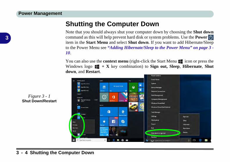
Power Management
3
Shutting the Computer DownNote that you should always shut your computer down by choosing the Shut downcommand as this will help prevent hard disk or system problems. Use the Power item in the Start Menu and select Shut down. If you want to add Hibernate/Sleepto the Power Menu see “Adding Hibernate/Sleep to the Power Menu” on page 3 -10.
You can also use the context menu (right-click the Start Menu icon or press theWindows logo + X key combination) to Sign out, Sleep, Hibernate, Shutdown, and Restart.
Figure 3 - 1Shut Down/Restart
3 - 4 Shutting the Computer Down

Power Management
3
Power PlansThe computer can be configured to conserve power by means of power plans (Con-trol Panel > Power Options). You can use (or modify) an existing power plan, orcreate a new one.
The settings may be adjusted to set the display to turn off after a specified time, andto send the computer into Sleep after a period of inactivity.
Click Change plan settings and then click Change advanced power settings to ac-cess further configuration options in Advanced Settings.
Resuming Operation
See Table 3 - 1, onpage 3 - 11 for informa-tion on how to resumefrom a power-savingstate.
Password
It is recommended thatyou enable a passwordon system resume in or-der to protect your data.
Figure 3 - 2Power Plan
Advanced Settings
Power Plans 3 - 5

Power Management
3
Each Windows power plan will also adjust the processor performance of your ma-chine in order to save power. This is worth bearing in mind if you are experiencingany reduced performance (especially under DC/battery power).
Choose High performance (you may need to click Show additional plans to viewthe High performance plan) for maximum performance when the computer is pow-ered from an AC power source. Choose the Power saver (bear in mind that thisscheme may slow down the overall performance of the computer in order to savepower) for maximum power saving when the computer is battery (DC power) pow-ered.
Figure 3 - 3Power Plans
Click to Show/Hide additional power plans
3 - 6 Power Plans

Power Management
3
Power-Saving StatesYou can use power-saving states to stop the computer’s operation and restart whereyou left off. Windows 10 uses the Sleep, Hibernate and Shut Down power-savingstates.
SleepIn Sleep all of your work, settings and preferences are saved to memory before thesystem sleeps. When you are not using your computer for a certain length of time,which you specify in the operating system, it will enter Sleep to save power.
The PC wakes from Sleep within seconds and will return you to where you last leftoff (what was on your desktop) without reopening the application(s) and file(s) youlast used.
If your mobile PC in Sleep is running on battery power the system will use only aminimum amount of power. After an extended period the system will save all theinformation to the hard disk and shut the computer down before the battery becomesdepleted.
To add Sleep to the Power Menu see “Adding Hibernate/Sleep to the PowerMenu” on page 3 - 10.
Wake On LAN
Support
Wake-On-LAN is onlysupported from Sleep orHibernate states inWindows.
If you require your com-puter to wake up fromnetwork activity in Win-dows then make surethat the computer is ei-ther in Sleep or Hiber-nate.
Wake-On-LAN is notsupported from Shut-down states in Win-dows.
Power-Saving States 3 - 7
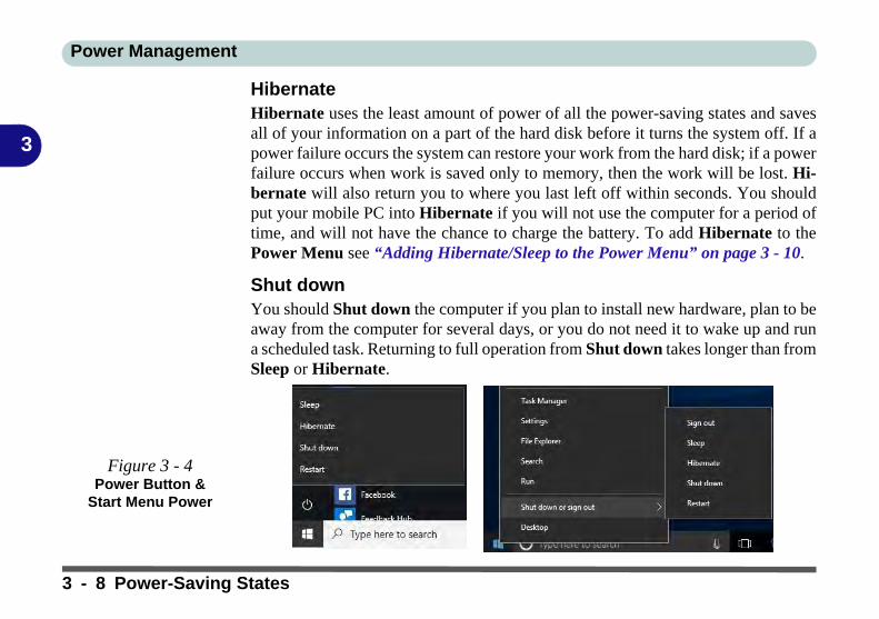
Power Management
3
HibernateHibernate uses the least amount of power of all the power-saving states and savesall of your information on a part of the hard disk before it turns the system off. If apower failure occurs the system can restore your work from the hard disk; if a powerfailure occurs when work is saved only to memory, then the work will be lost. Hi-bernate will also return you to where you last left off within seconds. You shouldput your mobile PC into Hibernate if you will not use the computer for a period oftime, and will not have the chance to charge the battery. To add Hibernate to thePower Menu see “Adding Hibernate/Sleep to the Power Menu” on page 3 - 10.
Shut downYou should Shut down the computer if you plan to install new hardware, plan to beaway from the computer for several days, or you do not need it to wake up and runa scheduled task. Returning to full operation from Shut down takes longer than fromSleep or Hibernate.
Figure 3 - 4Power Button &
Start Menu Power
3 - 8 Power-Saving States

Power Management
3
Configuring the Power ButtonsThe power/sleep button (Fn + F12 key combo) and closed lid may be set to send thecomputer in to a power-saving state. Click Choose what the power buttons do onthe left menu in Power Options to bring up the menu.
Password Protection
It is recommended thatyou enable a passwordon wake up in order toprotect your data.
However you can dis-able this setting from thePower Options menuby clicking Require apassword on wakeupin the left menu, and se-lecting the options (clickChange settings thatare currently unavail-able).
Figure 3 - 5Power Options Define Power
Buttons
Configuring the Power Buttons 3 - 9

Power Management
3
Adding Hibernate/Sleep to the Power MenuAdd Hibernate/Sleep to the Power Menu as follows.
1. Go to the Power Options (Hardware and Sound) control panel.2. Click “Change settings that are currently unavailable” .3. Click Choose what the power buttons do.4. Click to put a check in the Hibernate/Sleep box under Shutdown settings.5. Click Save Changes and close the control panel.
Figure 3 - 6Power Options Define Power
Buttons - Shutdown Settings
3 - 10 Configuring the Power Buttons

Power Management
3
Resuming OperationYou can resume operation from power-saving states by pressing the power button,or in some cases pressing the sleep button (Fn + F12 key combo).
Power Status Icon Color To Resume
Power Off Off Press the Power Button
Sleep Blinking White
Press the Power Button
Press the Sleep Button (Fn + F12 Key Combo)
HibernateOff (battery)
Press the Power ButtonOrange (AC/DC adapter)
Display Turned Off White Press a Key or Move the Mouse/Touchpad
Table 3 - 1Resuming
Operation
Closing the Lid
If you have chosen tosend the computer toSleep when the lid isclosed, raising the lidwill wake the system up.
Power Button
When the computer is on, you can use the power button as a Sleep/Hibernate/Shut Downhot key button when it is pressed for less than 4 seconds (pressing and holding the powerbutton for longer than this will force the computer to shut down).
Configuring the Power Buttons 3 - 11

Power Management
3
Ctrl + Alt + Delete Key CombinationYou can use the CTRL + ALT + DEL key combination from almost any of the Win-dows 10 interfaces/Apps to bring up a full-screen displaying Lock, Switch User,Sign out, Change a password and Task Manager options. If you click the Powericon in the lower right corner of the screen a power management option menu ap-pears to display Sleep, Shut down, and Restart.
To fully control all the power options (including Hibernate mode) go to the PowerOptions control panel and configure the power button, sleep button and lid to per-form the function selected.
Figure 3 - 7Ctrl + Alt + Delete
Menu
3 - 12 Configuring the Power Buttons

Power Management
3
Settings Menu Power ControlsThe Settings item in the Start Menu (or via the Action Center) gives you access toa number of power settings control panels which enable you to quickly adjust poweroptions. Click System to access the menu including the power option settings.
Figure 3 - 8Settings
Settings Menu Power Controls 3 - 13

Power Management
3
Battery SaverBattery in Settings will display the battery level, and by clicking Battery usage byapp you can see the current state of battery usage by application etc. The Batterysaver can be level can be adjusted to be turned on if the battery level falls below acertain level to limit background activity and push notifications.
Figure 3 - 9Settings > Battery >
Battery Saver
3 - 14 Settings Menu Power Controls
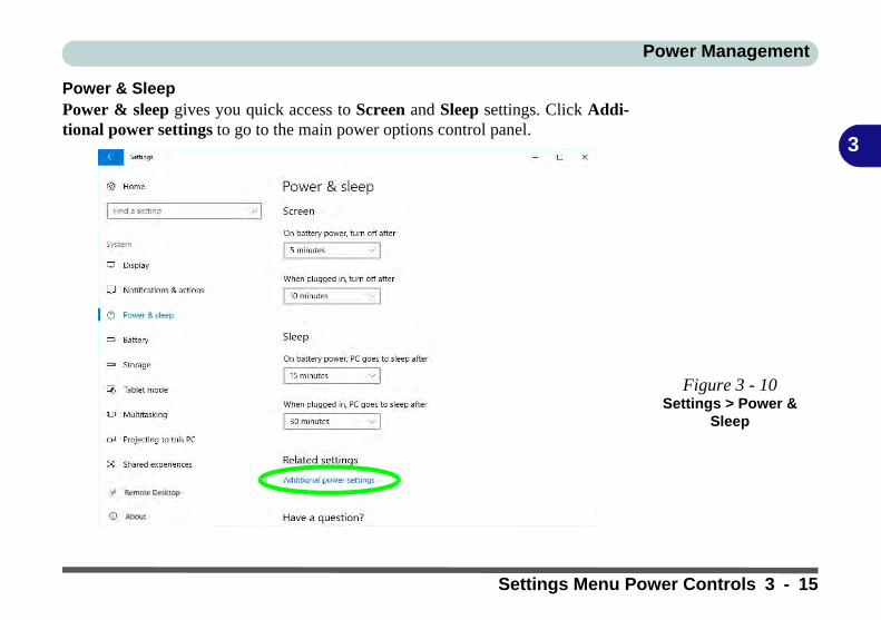
Power Management
3
Power & SleepPower & sleep gives you quick access to Screen and Sleep settings. Click Addi-tional power settings to go to the main power options control panel.
Figure 3 - 10Settings > Power &
Sleep
Settings Menu Power Controls 3 - 15

Power Management
3
Battery InformationFollow these simple guidelines to get the best use out of your battery.
Battery PowerYour computer’s battery power is dependent upon many factors, including the pro-grams you are running, and peripheral devices attached. You can set actions to betaken (e.g. Shut down, Hibernate etc.), and set critical and low battery levels frompower plan Change plan settings > Change advanced power settings (see Figure3 - 3 on page 3 - 6).
Click the battery icon in the notification area to see the current battery level andcharge status. You can also adjust the Power Slider towards Best battery life orBest performance, or click Battery Settings to quickly adjust battery settings).
Power Slider
The Power Slider (clickthe battery icon inthe notification area) letsyou trade performanceVs battery life, bychoose the power modeyou want (see over).
Figure 3 - 11Battery Icon
(Notification Area) & Battery Advanced
Settings
3 - 16 Battery Information

Power Management
3
Power Slider Settings
Battery Saver Better BatteryBetter
PerformanceBest
Performance
For DC Only For AC & DC
Lowest Power SettingLower Power than Default Settings
Slightly Favors Performance Over
Power
Favors Performance Over Power
Windows Features Throttled & Screen
Brightness ReducedDefault Position
Auto Enabled at 20% of Battery Capacity
Battery Saver
Note that some Win-dows features and back-ground applications maybehave differently, ormay be blocked, whenthe system is in BatterySaver mode (check withMicrosoft for details).
Table 3 - 2Power Slider
Settings & Notes
Battery Information 3 - 17

Power Management
3
Conserving Battery Power• Use a power plan that conserves power (e.g Power saver), however note that
this may have an affect on computer performance.
• Lower the brightness level of the LCD display. The system will decrease LCD brightness slightly to save power when it is not powered by the AC/DC adapter.
• Reduce the amount of time before the display is turned off.
• Close wireless, Bluetooth, modem or communication applications when they are not being used.
• Disconnect/remove any unnecessary external devices e.g. USB devices, ExpressCards etc.
Windows Mobility
Center
The Windows MobilityCenter control panelprovides an easy pointof access for informationon battery status, powerplans used and wirelessdevice status etc.
Figure 3 - 12Windows Mobility
Center (Control Panel)
3 - 18 Battery Information

Power Management
3
Battery LifeBattery life may be shortened through improper maintenance. To optimize the lifeand improve its performance, fully discharge and recharge the battery at leastonce every 30 days.
We recommend that you do not remove the battery yourself. If you do need to re-move the battery for any reason (e.g. long term storage) see “Removing the Battery”on page 3 - 25.
New BatteryAlways completely discharge, then fully charge, a new battery (see “Battery FAQ”on page 3 - 21 for instructions on how to do this).
Recharging the Battery with the AC/DC AdapterThe battery pack automatically recharges when the AC/DC adapter is attached andplugged into an electrical outlet. If the computer is powered on, and in use, it willtake several hours to fully recharge the battery. When the computer is turned off butplugged into an electrical outlet, battery charge time is less. Refer to “LED Indica-tors” on page 1 - 7 for information on the battery charge status, and to “BatteryFAQ” on page 3 - 21 for more information on how to maintain and properly re-charge the battery pack.
Battery Information 3 - 19

Power Management
3
Proper handling of the Battery Pack• DO NOT disassemble the battery pack under any circumstances• DO NOT expose the battery to fire or high temperatures, it may explode• DO NOT connect the metal terminals (+, -) to each other
Caution
Danger of explosion ifbattery is incorrectly re-placed.
Replace only with thesame or equivalent typerecommended by themanufacturer. Discardused battery accordingto the manufacturer’s in-structions.
Damaged Battery Warning
Should you notice any physical defects (e.g. the battery is bent out of shape after beingdropped), or any unusual smells emanating from the notebook battery, shut your computerdown immediately and contact your distributor/supplier. If the battery has been dropped wedo not recommend using it any further, as even if the computer continues to work with adamaged battery in place, it may cause circuit damage, which may possibly result in fire. Itis recommended that you replace your computer battery every two years.
3 - 20 Battery Information

Power Management
3
Battery FAQHow do I completely discharge the battery?Use the computer with battery power until it shuts down due to a low battery. Don’tturn off the computer even if a message indicates the battery is critically low, just letthe computer use up all of the battery power and shut down on its own.
1. Save and close all files and applications.2. Create a power plan for discharging the battery and set all the options to Never.
Figure 3 - 13Power Plan Create
Battery Information 3 - 21

Power Management
3
3. Click Change plan settings (after creating it) and click Change plan settings > Change advanced power settings.
Figure 3 - 14Change Plan
Settings / Change Advanced Power
Settings
3 - 22 Battery Information

Power Management
3
4. Scroll down to Battery and click + to expand the battery options.5. Choose the options below (click Yes if a warning appears):
• Low battery levels = 0%• Critical battery Levels = 1%• Low battery action = Do Nothing• Critical battery action (On battery) = Shut Down• Critical battery action (Plugged in) = Do Nothing
Figure 3 - 15Power Options
Advanced Settings - Battery
Battery Information 3 - 23

Power Management
3
How do I fully charge the battery?When charging the battery, don’t stop until the LED charging indicator light changesfrom orange to green.
How do I maintain the battery?Completely discharge and charge the battery at least once every 30 days or afterabout 20 partial discharges.
3 - 24 Battery Information

Power Management
3
Removing the BatteryWe recommend that you do not remove the battery yourself. If you do need to re-move the battery for any reason (e.g. long term storage) see below.
1. Turn the computer off, and turn it over.2. Slide the latch in the direction of the arrow.3. Slide the latch in the direction of the arrow, and hold it in place.4. Slide the battery out in the direction of the arrow .
Bottom Cover
Removal Warning
Do not remove any cov-er(s) and /or screw(s) forthe purposes of deviceupgrade as this may vio-late the terms of yourwarranty.
If you need to replace/remove the hard disk/RAM/optical device etc.,for any reason, pleasecontact your distributor/supplier for further infor-mation.
Figure 3 - 16Battery Removal
12
3
12
33
12
6 Cell Battery 9 Cell Battery
Removing the Battery 3 - 25

Power Management
3
Inserting the Battery1. Turn the computer off, and turn it over.2. Slide the battery into the compartment in the direction of the arrow .3. Slide the latches and in the direction of the arrows to lock the battery.
Figure 3 - 17Battery Insertion
12 3
1
2 33
1
2
6 Cell Battery 9 Cell Battery
3 - 26 Inserting the Battery

Drivers & Utilities
4
Chapter 4: Drivers & UtilitiesThis chapter deals with installing the drivers and utilities essential to the operation orimprovement of some of the computer’s subsystems. The system takes advantage ofsome newer hardware components for which the latest versions of most available op-erating systems haven’t built in drivers and utilities. Thus, some of the system com-ponents won’t be auto-configured with an appropriate driver or utility duringoperating system installation. Instead, you need to manually install some system-re-quired drivers and utilities.
What to InstallThe Device Drivers & Utilities + User’s Manual disc contains the drivers and util-ities necessary for the proper operation of the computer. Table 4 - 1, on page 4 - 4lists what you need to install and it is very important that the drivers are installedby the method outlined in this chapter, and in the order indicated.
Note that the information included on the following pages is for Windows 10 (64-bit)only.
Module Driver InstallationThe procedures for installing drivers for the Wireless LAN, Fingerprint, Bluetooth& WLAN Combo and Intel Technology modules are provided in “Modules & Op-tions” on page 6 - 1.
Driver Installation &
Power
When installing driv-ers make sure yourcomputer is poweredby the AC/DC adapterconnected to a work-ing power source.Some drivers draw asignificant amount ofpower during the instal-lation procedure, and ifthe remaining batterycapacity is not adequatethis may cause the sys-tem to shut down andcause system problems(note that there is nosafety issue involvedhere, and the battery willbe rechargeable within 1minute).
What to Install 4 - 1

Drivers & Utilities
4
Driver Installation1. Insert the Device Drivers & Utilities + User’s Manual disc into the DVD drive.2. Click the message “Tap to choose what happens with this disc.”3. Click Run autorun.exe.4. Click Install Drivers (button), or Option Drivers (button) to access the Optional driver menu.
Figure 4 - 1 - Drivers Installer Screen 1
4 - 2 Driver Installation

Drivers & Utilities
4
5. Check the driver installation order from Table 4 - 1, on page 4 - 4 (the drivers must be installed in this order) which is the same as that listed in the Drivers Installer menu below.
6. Click to select the driver you wish to install, (you should note down the drivers as you install them).7. Follow the instructions for each individual driver installation procedure as listed on the following pages.
Figure 4 - 2 - Install Drivers
Driver Installation 4 - 3

Drivers & Utilities
4
Table 4 - 1 - Driver Installation
All drivers provided are for the Windows 10 (64-bit) operating system.
Note that you need to install both the WLAN & Bluetooth drivers for the WLAN & Bluetooth Combo modules.
Win 10 Drivers (64-bit) System Required
Page # Win 10 Drivers (64-bit) Other / Options Page #
Chipset Page 4 - 7 Wireless LAN Module Page 6 - 3
Video (VGA) Page 4 - 7 Bluetooth Combo Module Page 6 - 8
LAN Page 4 - 7 Fingerprint Reader Module Page 6 - 14
CardReader Page 4 - 7 Intel® Software Guard Extensions Page 6 - 18
Touchpad Page 4 - 7Intel® Rapid Storage Technology (required for hard disks in AHCI/RAID mode)
Page 6 - 19
Control Center Page 4 - 8 PC Camera Module (No driver required) Page 6 - 23
Airplane Page 4 - 8 Trusted Platform Module (No driver required) Page 6 - 29
MEI Driver Page 4 - 8 3G/4G Module (No driver required) Page 6 - 35
Audio Page 4 - 8
4 - 4 Driver Installation

Drivers & Utilities
4
Manual Driver InstallationClick Browse CD/DVD (button) in the Drivers Install-er application and browse to the executable file in theappropriate driver folder.
Windows UpdateAfter installing all the drivers make sure you enableCheck for updates (Settings > Update & security >Check for updates) in order to get all the latest secu-rity updates etc. (all updates will include the latest hot-fixes from Microsoft). See “Windows Update” onpage 4 - 9 for instructions.
Updating/Reinstalling Individual DriversIf you wish to update/reinstall individual drivers itmay be necessary to uninstall the original driver.To dothis go to the Control Panel in the Windows OS anddouble-click the Programs icon (Programs > Unin-stall a program). Click to select the driver (if it is notlisted see below) and click Uninstall, and then followthe on screen prompts (it may be necessary to restartthe computer). Reinstall the driver as outlined in thischapter.
If the driver is not listed in the Programs and Fea-tures menu:
1. Go to the Control Panel).2. Double-click Device Manager (Hardware and
Sound > Devices and Printers > Device Manager).
3. Double-click the device you wish to update/reinstall the driver for (you may need to click “+” to expand the selection).
4. Click Driver (tab) and click the Update Driver or Uninstall button and follow the on screen prompts.
Driver Installation 4 - 5

Drivers & Utilities
4
User Account ControlIf a User Account Control prompt appears as part ofthe driver installation procedure, click Continue orAllow, and follow the installation procedure as direct-ed.
Windows Security MessageIf you receive a Windows security message as part ofthe driver installation process. Just click “Install thisdriver software anyway” or “Install” to continue theinstallation procedure.
You will receive this message in cases where the driv-er has been released after the version of Windows youare currently using. All the drivers provided will havealready received certification for Windows.
New Hardware FoundIf you see the message “New Hardware Found” dur-ing the installation procedure (other than when out-lined in the driver install procedure), click Cancelto close the window, and follow the installation proce-dure.
Driver Installation General Guidelines
The driver installation procedure outlined in this Chapter(and in Chapter 7 Options & Modules), are accurate atthe time of going to press.
Drivers are always subject to upgrade and revision sothe exact procedure for certain drivers may differ slight-ly. As a general guide follow the default on screen in-structions for each driver (e.g. Next > Next > Finish)unless you are an advanced user. In many cases a re-start is required to install the driver.
Make sure any modules (e.g. WLAN or Bluetooth) areON (i.e. the system is not in Airplane Mode) beforeinstalling the appropriate driver.
4 - 6 Driver Installation

Drivers & Utilities
4
Driver Installation ProcedureInsert the Device Drivers & Utilities + User’s Manualdisc into your DVD drive and click Install Drivers(button).
Chipset1. Click 1.Install Chipset Driver > Yes.2. Click Next > Accept > Install.3. Click Restart Now to restart the computer.
Video (VGA)1. Click 2.Install VGA Driver > Yes.2. Click Next > Yes > Next > Next.3. Click Finish to restart the computer.
LANNote: If the computer enters a deep sleep mode duringinstallation, you will be prompted to plug in a networkcable, and click OK, to continue installation. If a net-work cable is not available, restart the system and re-install the LAN driver.
1. Click 3.Install LAN Driver > Yes.2. Click Install Drivers and Software > Next.3. Click the button to accept the license and click
Next.4. Click Next > Install.5. Click Finish.
CardReader1. Click 4.Install Cardreader Driver > Yes.2. Click Finish.
Touchpad1. Click 5.Install Touchpad Driver > Yes.2. Click Next.3. Click the button to accept the license, and then
click Next.4. Click Finish > Restart Now to restart the com-
puter.
Driver Installation 4 - 7

Drivers & Utilities
4
Control Center1. Click 6.Install Control Center AP > Yes. 2. Click Next > Install.3. Click Finish to restart the computer.
AirplaneNote: Do not use Update Driver in Device Manager toinstall the Airplane Mode driver.
1. Click 7.Install Airplane Mode AP > Yes. 2. Click Next > Install.3. Click Finish to restart the computer.
MEI Driver1. Click 8.Install MEI Driver > Yes.2. Click Next.3. Click the check box to accept the license and
then click Next.4. Click Next.5. Click Finish.
Audio1. Click 9.Install Audio Driver > Yes. 2. Click Next.3. Click Finish to restart the computer.
Note that after installing the audio driver the systemwill not return to the Drivers Installer screen. To in-stall any of the optional drivers listed overleaf, ejectthe Device Drivers & Utilities + User’s Manual discand then reinsert it (or double-click the disc icon in MyComputer), and click Option Drivers (button) to ac-cess the optional driver menu.
It is recommended you now also install the Intel Rap-id Storage Technology driver (see “Intel® RapidStorage Technology” on page 6 - 19 - required forAHCI mode hard disks).
4 - 8 Driver Installation

Drivers & Utilities
4
Windows Update
After installing all the drivers make sure you enable Win-dows Update in order to get all the latest security up-dates etc. (all updates will include the latest hotfixesfrom Microsoft).
To enable Windows Update make sure you are con-nected to the internet:
1. Go to the Control Panel.2. Click Windows Update (System and Security/
Security).3. Click Check for updates (button).4. The computer will now check for updates (you
need to be connected to the internet).5. Click Install now (button) to begin checking for the
updates.6. Click Install updates (button) to install the
updates.
Driver Installation 4 - 9

Drivers & Utilities
4
Optional DriversSee the pages indicated in Table 4 - 1, on page 4 - 4 for the driver installation procedures for any modules in-cluded in your purchase option.
Figure 4 - 3 - Option Drivers
Note that you need to install both the WLAN & Bluetooth drivers for Intel and 3rd party WLAN & BluetoothCombo modules.
4 - 10 Optional Drivers

BIOS Utilities
5
Chapter 5: BIOS Utilities
OverviewThis chapter gives a brief introduction to the computer’s built-in software:
If your computer has never been set up, or you are making important changes to thesystem (e.g. hard disk setup), then you should review this chapter first and note theoriginal settings found in Setup. Even if you are a beginner, keep a record of the set-tings you find and any changes you make. This information could be useful if yoursystem ever needs servicing.
There is one general rule: Don’t make any changes unless you are sure of what youare doing. Many of the settings are required by the system, and changing them couldcause it to become unstable or worse. If you have any doubts, consult your servicerepresentative.
BIOS Screens
Note that the BIOSscreens pictured onthese pages are intend-ed for guidance in set-ting up your system’sBIOS.
BIOS versions are sub-ject to constant changeand revision, thereforeyour computer’s actualscreens may appearslightly different fromthose pictured on thesepages.
Overview 5 - 1

BIOS Utilities
5
The Setup UtilityEach time you turn on the computer the system takes a few seconds to conduct aPOST, including a quick test of the on-board RAM (memory).
As the POST proceeds, the computer will tell you if there is anything wrong. If thereis a problem that prevents the system from booting, it will display a system summaryand prompt you to run Setup.
If there are no problems, the Setup prompt will disappear and the system will loadthe operating system. Once that starts, you can’t get into Setup without rebooting.
The Aptio Setup Utility tells the system how to configure itself and manage basicfeatures and subsystems (e.g. port configuration).
To enter Setup, turn on the computer and press F2 (give the system a few secondsto enter Setup). If the Boot Logo is enabled the F2 on screen will be highlighted toillustrate that the system is processing the request during the POST (or press F7 forboot options). If you get a “Keyboard Error”, (usually because you pressed F2 tooquickly) just press F2 again.
If the computer is already on, reboot using the Ctrl + Alt + Delete combination andthen hold down F2 when prompted. The Setup main menu will appear.
To see the boot options press F7 and choose your preferred boot device.
BIOS Settings
Warning
Incorrect settings cancause your system tomalfunction. To correctmistakes, return to Set-up and restore the Opti-mized Defaults with<F3>.
UEFI Boot & POST
When UEFI Boot is en-abled, then the promptsto press F2 or F7 willnot appear. Howeveryou can still press F2 toenter the setup, or F7 tochoose the preferredboot device, if you pressthe key immediately thesystem boots up.
5 - 2 The Setup Utility

BIOS Utilities
5
Failing the POSTErrors can be detected during the POST. There are two categories, “fatal” and “non-fatal”.
Fatal ErrorsThese stop the boot process and usually indicate there is something seriously wrongwith your system. Take the computer to your service representative or authorizeddistributor/supplier as soon as possible.
Non-Fatal ErrorsThis kind of error still allows you to boot. You will get a message identifying theproblem (make a note of this message!) and you can then press F7 (the F7 on screenwill be highlighted to illustrate that the system is processing the request) for bootoptions.
Press F2 (give the system a few seconds to enter Setup; the F2 on screen will behighlighted to illustrate that the system is processing the request) to run the Setupprogram and try to correct the problem. If you still get an error message after youchange the setting, or if the “cure” seems even worse, call for help.
The Setup Utility 5 - 3

BIOS Utilities
5
Setup ScreensThe following pages contain additional advice on portions of the Setup. Along thetop of the screen is a menu bar with menu headings. When you select a heading, anew screen appears. Scroll through the features listed on each screen to make chang-es to Setup.
Instructions on how to navigate each screen are in the box at the bottom right side ofthe screen.
If these tools are confusing, press F1 to call up a General Help screen, and then usethe arrow keys to scroll up or down the page.
The Item Specific Help on the upper right side of each screen explains the highlight-ed item and has useful messages about its options.
If you see an arrow next to an item, press Enter to go to a sub-menu on that sub-ject. The sub-menu screen that appears has a similar layout, but the Enter key mayexecute a command.
Setup Menus
The Setup menusshown in this section arefor reference only. Yourcomputer’s menus willindicate the configura-tion appropriate for yourmodel and options.
Figure 5 - 1Navigation Menu
5 - 4 The Setup Utility

BIOS Utilities
5
Main Menu
System Time & Date (Main Menu)The hour setting uses the 24-hour system (i.e., ØØ = midnight; 13 = 1 pm). If youcan change the date and time settings in your operating system, you will also changethese settings. Some applications may also alter data files to reflect these changes.
Figure 5 - 2Main Menu
Main Menu 5 - 5

BIOS Utilities
5
SATA Port # (Main Menu)Pressing Enter opens the sub-menu to show the configuration of a optical Device/HDD on the computer’s SATA Ports.
OffBoard SATA/NVme Controller Configuration (Main Menu)Pressing Enter opens the sub-menu to show the configuration of any devices on theoff board SATA/NVme Controller if applicable.
CPU/ ME FW Version / System/ Extended Memory: (Main Menu)This item contains information on the CPU type and system memory, and is not userconfigurable. The system will auto detect the amount of memory installed.
MB Series / BIOS Revision / KBC/EC firmware Revision / Mac Address (MainMenu)This item contains information on the BIOS version etc., and is not user configu-rable.
Docking Station Hard Disk Drives
Note that hard diskdrives installed in thedocking station will bedisplayed as externalHDDs in the BIOS.
5 - 6 Main Menu

BIOS Utilities
5
Advanced Menu
Figure 5 - 3Advanced Menu
Advanced Menu 5 - 7

BIOS Utilities
5
Advanced Chipset Control (Advanced Menu)The sub-menu here allows you to enable/disable Flexicharger, Software GuardExtensions, VT-d and Fast Boot.
Figure 5 - 4Advanced Menu > Advanced Chipset
Control
5 - 8 Advanced Menu

BIOS Utilities
5
FlexiCharger (Advanced Menu > Advanced Chipset Control)The sub-menu here allows you to enable/disable the FlexiCharger. The FlexiCharg-er may be set to automatically start charging your battery when the battery reachesa certain capacity level (e.g. you could start the battery charge level at 40%).
You can then set the level to stop charging (e.g. 100%), and of course this stopcharge level must be higher then the start charge level.
See the sidebar warning for information on running the FlexiCharger for an ex-tended period as this is not recommended.
FlexiCharger
Warning
If you leave the FlexiCh-arger continuously "En-abled” for a period ofthree months or more,the battery meter's read-ing accuracy will deteri-orate.
To reset this, set theFlexiCharger to "Dis-abled", and then allowthe battery to completelydischarge (see “BatteryFAQ” on page 3 - 21)before enabling thefunction again.
Figure 5 - 5Advanced Chipset
Control > FlexiCharger
Advanced Menu 5 - 9

BIOS Utilities
5
Software Guard Extensions (Advanced Menu > Advanced Chipset Control)Intel provides SGX, which is a set of instructions allowing user-level code a degreeof security, and privacy, from the operating system. This is disabled by default andshould be enabled before installing the driver (see page 6 - 18).
VT-d (Advanced Menu > Advanced Chipset Control)Enable/disable Intel® Virtualization Technology for Directed I/O (VT-d) fromthis menu. This extends Intel's Virtualization Technology (VT) by providing hard-ware assists for a virtualization solution.
Fast Boot(Advanced Menu > Advanced Chipset Control)Use this menu item to enable/disable the Fast Boot option, which when enabled,helps reduce the time it takes to boot the computer.
Intel Virtualization Technology (Advanced Menu > Advanced Chipset Control)(For Model A Computers Only)Intel(R) Virtualization Technology enables a CPU to act as if it were several CPUsworking in parallel in order to allow several operating systems to run at the sametime in the same machine.
5 - 10 Advanced Menu

BIOS Utilities
5
SATA Mode (Advanced Menu)The SATA (Serial ATA) controller operates in AHCI (Advanced Host ControllerInterface) mode. Install the Intel Rapid Storage Technology driver to support yourdrive in AHCI mode (see “Intel® Rapid Storage Technology” on page 6 - 19).
Power On Boot Beep (Advanced Menu)Use this menu item to enable/disable the beep as the computer starts up.
Battery Low Alarm Beep (Advanced Menu)Use this menu item to enable/disable the battery low alarm beep.
Advanced Menu 5 - 11

BIOS Utilities
5
Security Menu
Set Supervisor Password (Security Menu)You can set a password for access to the Aptio Setup Utility. This will not affectaccess to the computer OS (only the Aptio Setup Utility). If you set a supervisorpassword you can then add a user password and password on boot.
Security Menu
The changes you makehere affect the accessto the Setup utility itself,and also access to yourmachine as it boots upafter you turn it on.These settings do notaffect your machine ornetwork passwordswhich will be set in yoursoftware OS.
Figure 5 - 6Security Menu
5 - 12 Security Menu
BIOS Utilities
5
Set User Password (Security Menu)You can set a password for user mode access to the Aptio Setup Utility. This willnot affect access to the computer OS, (only the Setup utility) unless you choose toset a Password on Boot (see below). Many menu items in the Aptio Setup Utilitycannot be modified in user mode. You can only set the user password after youhave set the supervisor password.
Password on boot (Security Menu)Specify whether or not a password should be entered to boot the computer (you mayonly set a password on boot if a supervisor password is enabled). If “Enabled”is selected, only users who enter a correct password can boot the system (see thewarning in the sidebar). The default setting is “Disabled”.
Note: To clear existing passwords press Enter and type the existing password, thenpress Enter for the new password (without typing any password entry) and Enteragain to confirm the password clearance.
Password Warning
If you set a boot pass-word (Password on bootis “Enabled“), NEVERforget your password.
The consequences ofthis could be serious. Ifyou cannot rememberyour boot password youmust contact your ven-dor and you may lose allof the information onyour hard disk.
Security Menu 5 - 13

BIOS Utilities
5
Secure Boot Support (Security Menu)Secure Boot prevents unauthorized operating systems and software from loadingduring the startup process. Secure Boot Support is available as a menu option if youhave enabled UEFI Boot (see “UEFI Boot (Boot Menu > UEFI Setting)” onpage 5 - 17). Enabling Secure Boot will bring up the Secure Boot Mode menu toenable you to configure Secure Boot as Standard (with a fixed secure boot policy)or Custom (which enables you to make changes to the Key Management database).
Figure 5 - 7Security
(Key Management)
5 - 14 Security Menu

BIOS Utilities
5
TPM Configuration (Security Menu)This sub-menu will allow you to enable/disable Trusted Platform Module (TPM)support, and to configure the TPM State. Select TPM Configuration and press En-ter to access the sub-menu. Press Enter to access the Security Device Support menuand select Enable to display the full TPM configuration menu (see “Trusted Plat-form Module” on page 6 - 29 for details).
Figure 5 - 8TPM Configuration
Security Menu 5 - 15

BIOS Utilities
5
Boot Menu
When you turn the computer on it will look for an operating system (e.g. Windows8.1) from the devices listed in this menu, and in this priority order. If it cannot findthe operating system on that device, it will try to load it from the next device in theorder specified in the Boot Option Priorities.
Figure 5 - 9Boot Menu
BIOS Screens
Note that the BIOSscreens pictured onthese pages are intend-ed for guidance in set-ting up your system’sBIOS.
BIOS versions are sub-ject to constant changeand revision, thereforeyour computer’s actualscreens may appearslightly different fromthose pictured on thesepages.
5 - 16 Boot Menu

BIOS Utilities
5
Boot Option Priorities (Boot Menu)Press Enter to access the menu and use the arrow keys to move up and down theavailable options (the selected device will be highlighted in white).
UEFI Boot (Boot Menu > UEFI Setting)Enable/disable UEFI Boot from this menu. The Unified Extensible Firmware Inter-face (UEFI) specification provides a clean interface between operating systems andplatform firmware at boot time. In contrast to BIOS, UEFI defines a set of standardboot and runtime services.
Boot Menu 5 - 17

BIOS Utilities
5
Exit Menu
Click Save Changes and Reset to save all changes made. Choosing to DiscardChanges, or Exit Discarding Changes, will wipe out any changes you have madeto the Setup. You can also choose to restore the original Setup defaults that will re-turn the Setup to its original state, and erase any previous changes you have made ina previous session.
Figure 5 - 10Exit Menu
5 - 18 Exit Menu

Modules & Options
6
Chapter 6: Modules & OptionsOverviewThis chapter contains information on the following modules, which may come withyour computer, depending on the configuration purchased. If you are unsure pleasecontact your service representative.
Wireless Device
Operation Aboard Aircraft
The use of any portableelectronic transmission de-vices aboard aircraft is usu-ally prohibited. Make surethe module(s) are OFF ifyou are using the computeraboard aircraft.
Driver Installation &
Module Power
Make sure any modules(e.g. WLAN, PC Camera,3G/4G & Bluetooth mod-ules) are ON before install-ing the appropriate driver.
• Wireless LAN Module• Bluetooth Combo Module• Fingerprint Reader Module• Intel® Software Guard Extensions• Intel® Rapid Storage Technology
• Intel® vPro™ Technology• PC Camera Module• Trusted Platform Module• 3G/4G Module
Overview 6 - 1

Modules & Options
6
Important Notice
If your purchase option includes both Wireless LAN and 3G/4G modules, then the appro-priate antennas will be installed. Note that In order to comply with FCC RF exposure com-pliance requirements, the antenna must not be co-located or operate in conjunction withany other antenna or transmitter.
Important Notice - 3G/4G & Bluetooth/Wireless LAN Modules
In order to comply with FCC regulations you should NOT operate the 3G/4G module andthe Bluetooth/Wireless LAN modules at the same time as this may disrupt radio frequency,and cause interference. When the 3G/4G module is powered on, make sure that the Blue-tooth/Wireless LAN modules are powered off.
6 - 2 Overview

Modules & Options
6
Wireless LAN ModuleIf you have included an Intel® or 3rd Party 802.11b/g/n (Combo) module is on(i.e. the system is not in Airplane Mode) before installing the driver.
Make sure you install the drivers in the order indicated in Table 4 - 1, on page 4 - 4.
Note that you need to install both the WLAN & Bluetooth drivers for the WLAN& Bluetooth Combo modules.
See overleaf for the appropriate driver installation instructions.
Wireless Device
Operation Aboard Aircraft
The use of any portableelectronic transmissiondevices aboard aircraftis usually prohibited.Make sure the WLAN/Bluetooth module(s)are OFF if you are usingthe computer aboardaircraft. Use AirplaneMode hot key to toggleAirplane Mode On/Off,and check the LED indi-cator for the power sta-tus.
Wireless LAN Module 6 - 3

Modules & Options
6
3rd Party 802.11b/g/n Driver Installation1. Make sure the system is not in Airplane Mode, and then insert the Device
Drivers & Utilities + User’s Manual disc into an attached DVD drive. 2. Click Option Drivers (button).3. Click 1.Install WLAN Driver > Yes.4. Click Next.5. Click Finish to restart the computer.6. The operating system is the default setting for Wireless LAN control in
Windows (see page 6 - 5).
Intel® WLAN Driver Installation1. Make sure the system is not in Airplane Mode, and then insert the Device
Drivers & Utilities + User’s Manual disc into an attached DVD drive. 2. Click Option Drivers (button).3. Click 1.Install WLAN Driver > Yes.4. Click in the check box to agree to the End User License Agreement and click
Install.5. Click Finish.6. The operating system is the default setting for Wireless LAN control in
Windows (see page 6 - 5).
6 - 4 Wireless LAN Module

Modules & Options
6
WLAN Configuration in WindowsYou can configure a wireless connection using one of the following options, how-ever make sure the Wireless LAN module is turned on (and not in Airplane Mode)before configuration begins.
1. Click the Wireless icon in the notification area of the taskbar.2. Make sure that Airplane mode is off (the Airplane mode icon should be gray).3. A list of available access points will appear.4. Double-click an access point to connect to it (or click it and click Connect).
Figure 6 - 1WiFi & Network
Connections
Wireless LAN Module 6 - 5

Modules & Options
6
5. Enter a network security key (password) if required, and click Next.6. You can choose to share or connect to devices or not.7. When you are connected to the network access point it will display Connected
status .8. Select any connected network and click Disconnect to disconnect
from a connected access point.
Figure 6 - 2Network Connected (Click Disconnect)
Wireless Device
Operation Aboard Aircraft
The use of any portable electronictransmission devices aboard aircraft isusually prohibited.
Make sure the module is either OFF orin Airplane mode if you are using thecomputer aboard aircraft.
6 - 6 Wireless LAN Module

Modules & Options
6
9. You can click the Airplane Mode button to turn the mode On or Off.10. You need to either use Airplane Mode, or turn the WLAN module off aboard
aircraft.11. Network & Internet in Windows Settings will bring up a more comprehensive list
of network and internet settings including Wi-Fi (can be turned on/off), Airplane mode (Airplane mode and Wireless devices can be turned on/off) VPN, Dial-up, Ethernet and Proxy.
Figure 6 - 3Network & Internet
Settings
Wireless LAN Module 6 - 7
Modules & Options
6
Bluetooth Combo ModuleIf your purchase option includes the Combination Wireless LAN & Bluetoothmodule (either Intel® or 3rd Party) then install the driver as instructed overleaf.
Make sure that the module is on (i.e. the system is not in Airplane Mode) before in-stalling the driver.
Note that you need to install both the WLAN & Bluetooth drivers for the WLAN& Bluetooth Combo modules.
Wireless Device
Operation Aboard Aircraft
The use of any portableelectronic transmissiondevices aboard aircraftis usually prohibited.Make sure the WLAN/Bluetooth module(s)are OFF if you are usingthe computer aboardaircraft. Use AirplaneMode hot key to toggleAirplane Mode On/Off,and check the LED indi-cator for the power sta-tus.
Bluetooth Data Transfer
Note that the transfer of data between the computer and a Bluetooth enabled device is supportedin one direction only (simultaneous data transfer is not supported). Therefore if you are copyinga file from your computer to a Bluetooth enabled device, you will not be able to copy a file fromthe Bluetooth enabled device to your computer until the file transfer process from the computerhas been completed.
6 - 8 Bluetooth Combo Module

Modules & Options
6
3rd Party Bluetooth (V4.0) Combo Driver Installation1. Make sure the system is not in Airplane Mode, and then insert the Device
Drivers & Utilities + User’s Manual disc into an attached DVD drive. 2. Click Option Drivers (button).3. Click 2.Install Combo BT Driver > Yes.4. Click Next.5. Click Finish to restart the computer.6. See “Bluetooth Configuration in Windows” on page 6 - 10 for configura-
tion instructions.
Intel Bluetooth Combo Driver Installation1. Make sure the system is not in Airplane Mode, and then insert the Device
Drivers & Utilities + User’s Manual disc into an attached DVD drive. 2. Click Option Drivers (button).3. Click 2.Install Combo BT Driver > Yes.4. Click Next > Next.5. Click in the check box to accept the license and click Next.6. Select the setup type (Typical is recommended) and click Install.7. Click Finish.8. See “Bluetooth Configuration in Windows” on page 6 - 10 for configura-
tion instructions.
Bluetooth Combo Module 6 - 9

Modules & Options
6
Bluetooth Configuration in Windows1. Go to the Settings control panel and click Devices (or click the Bluetooth icon
in the taskbar and click Add a Bluetooth Device).2. Click Bluetooth & other devices and make sure Bluetooth is On.3. Click Add Bluetooth or other device > Bluetooth (Add a device) and a list of
discovered devices will appear.
Figure 6 - 4Settings > Bluetooth
& Other Devices (Add a Bluetooth
Device)
Figure 6 - 5Add a Device
6 - 10 Bluetooth Combo Module

Modules & Options
6
4. Double-click the device you want to pair with the computer and click Connect, if the PIN matches that on the device to which you wish to connect (you may need to click paid on the device).
Figure 6 - 6Bluetooth Connect
Bluetooth Combo Module 6 - 11

Modules & Options
6
5. Select a device and click Remove Device to disconnect from any device (click Yes to confirm).
Figure 6 - 7Bluetooth Remove
Device
6 - 12 Bluetooth Combo Module

Modules & Options
6
To Make your Computer Discoverable to Bluetooth Devices1. Go to the Settings control panel and click Devices (or click the Bluetooth icon
in the taskbar and click Open Settings).2. Click Bluetooth & other devices and click More Bluetooth options.3. In Bluetooth Settings make sure that Allow Bluetooth devices to find this PC
check box (Discovery) has a check inside it.4. Make sure that the Alert me when a new Bluetooth device wants to connect
check box (Notifications) has a check inside it, if you want to be notified when a Bluetooth device wants to connect.
Figure 6 - 8Bluetooth Settings
Bluetooth Combo Module 6 - 13

Modules & Options
6
Fingerprint Reader ModuleThe fingerprint reader module provides a high level of security for your computer.Make sure you have administrator’s rights to your computer, and have a Windowspassword enabled for full security protection.
There are two different fingerprint modules supplied with this model. Install thedriver from the Device Drivers & Utilities + User’s Manual disc by following theappropriate instructions on the page overleaf.
The fingerprint reader module uses the Sign-in options configuration of the Win-dows Account.
Fingerprint Reader and Power Saving
States
If your computer is in apower saving state (e.g.Hibernate or Sleep) youshould keep your fingerclear of the fingerprintsensor.
Allow the system to fullyresume before swipingyour finger across thesensor.
6 - 14 Fingerprint Reader Module

Modules & Options
6
Fingerprint Reader Driver Installation1. Make sure the system is not in Airplane Mode, and then insert the Device
Drivers & Utilities + User’s Manual disc into the DVD drive. 2. Click Option Drivers.3. Click 3.Install Fingerprint Driver > Yes.4. Click Next > Install.5. Click Finish to complete the installation.6. The fingerprint reader module uses the Sign-in options configuration of the
Windows Account (see overleaf).
Fingerprint Reader Module 6 - 15

Modules & Options
6
Fingerprint Module Configuration1. Click the Settings item in the Start Menu and then click Accounts and click Sign-
in options.2. You will need to add a Windows password (click Add under Password).3. After you have added the password you will need to also add a PIN.4. Under Windows Hello click Set up under Fingerprint.5. The wizard will then guide you through the set up process to scan your fingerprints.
PIN Code
You will be asked to adda PIN code when settingup the Fingerprint Read-er. This is in addition toyour windows pass-word.
Note this code as it maybe required to help yousign-in if there are anyissues with using the fin-gerprint reader to sign-in(see “Fingerprint Sign-In Issues” on page 6 -17).
Figure 6 - 9Accounts - Sign-in
options (Add Fingerprint)
6 - 16 Fingerprint Reader Module

Modules & Options
6
6. You will be instructed to swipe the same finger across the reader a number of times (this may be in excess of 20 times).
7. Try to present different parts of your finger in different positions (similar to the various positions you may use when using it, and if you see red at any point try a different position).
8. Click Close when complete.9. You can choose to Add another finger (this is recommended) or Remove the
current fingerprint reading.10. You can now scan your fingerprint to log-on to the computer.
Fingerprint Sign-In Issues
If at the Windows Hello screen, the Fingerprint reader fails to recognize the fingerprint3 times it will then block access to the computer.
In this case you will need to use your PIN (the PIN you used when initially setting up thefingerprint reader) to access the computer. Alternatively you can sign-in using your win-dows password.
After using the PIN code (or windows Password) to access the computer you can go to theSettings > Accounts > Sign-in options if you wish to change any settings.
Fingerprint Reader Module 6 - 17

Modules & Options
6
Intel® Software Guard ExtensionsInstall the Intel® Software Guard Extensions Driver which provides a set of in-structions allowing user-level code a degree of security, and privacy, from the oper-ating system.
Intel SGX Driver InstallationMake sure you have enabled Software Guard Extensions from Advanced ChipsetControl in the Advanced Menu in the BIOS before installing the driver (see “Soft-ware Guard Extensions (Advanced Menu > Advanced Chipset Control)” onpage 5 - 10).
1. Make sure the system is not in Airplane Mode, and then insert the Device Drivers & Utilities + User’s Manual disc into the DVD drive.
2. Click Option Drivers.3. Click 4.Install Intel SGX Driver > Yes.4. Click Next.5. Click in the check box to accept the license, and then click Next.6. Click Next > Install.7. Click Finish.8. Click the Intel Management and Security Status app to access the control
panel.
6 - 18 Intel® Software Guard Extensions

Modules & Options
6
Intel® Rapid Storage TechnologyInstall the Intel® Rapid Storage Technology to support your AHCI mode SATAdrive (see “SATA Mode (Advanced Menu)” on page 5 - 11).
IRST Driver Installation1. Insert the Device Drivers & Utilities + User’s Manual disc into an attached
DVD drive.2. Click Option Drivers (button).3. Click 5.Install IRST Driver > Yes.4. Click Next.5. Click in the check box to accept the license, and then click Next.6. Click Next > Next > Next.7. Click Finish to restart the computer.8. Run the Intel® Rapid Storage Technology app from the Apps screen.
IRST and M.2 PCI-e
SSDs
Note that Intel® RapidStorage Technologydoes not support M.2SSDs with a PCI-e In-terface (M.2 SSDs witha SATA Interface aresupported).
Intel® Rapid Storage Technology 6 - 19

Modules & Options
6
Intel® vPro™ TechnologyIntel® vPro™ Technology is supported by Model A computers only. This set oftechnology features, built into the computer’s motherboard, allows InformationTechnology departments remote access to the computer. This allows the IT depart-ment to monitor, maintain and manage computers regardless of the state of the op-erating system or the computer’s power state. This can be done over a wired orcorporate wireless network, or even outside the corporate firewall through a wiredLAN connection.
Accessing the Intel Management EngineTo access the Intel Management Engine press Ctrl + P at startup. Your system ad-ministrator will need to assist you in managing the information as applicable to yourenterprise. Note the following password information for the Intel Management En-gine:
• The default password is “admin” (without quotes).
If you get an "Error - Intel(R) ME password change rejected" message when cre-ating a new password, then note the following parameters for creating a password:
• between 8 and 32 characters long • Contain both upper and lower case Latin characters • Have at least one numeric character • Have at least one ASCII non-alphanumeric character (!, @, #, $,%, ^, &, *)
Wake On LAN From
G3 Power-Saving States
Only Model A computers,which support Intel®vPro™ Technology, can re-sume from network activity(Wake On LAN) from a G3(mechanical off) power-saving state.
A G3 (mechanical off) pow-er-saving state is when thepower is completely re-moved from the systeme.g. the system is un-plugged or power is turnedoff at a power strip.
6 - 20 Intel® vPro™ Technology
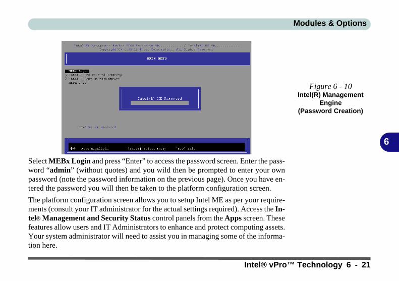
Modules & Options
6
Select MEBx Login and press “Enter” to access the password screen. Enter the pass-word “admin” (without quotes) and you wild then be prompted to enter your ownpassword (note the password information on the previous page). Once you have en-tered the password you will then be taken to the platform configuration screen.
The platform configuration screen allows you to setup Intel ME as per your require-ments (consult your IT administrator for the actual settings required). Access the In-tel® Management and Security Status control panels from the Apps screen. Thesefeatures allow users and IT Administrators to enhance and protect computing assets.Your system administrator will need to assist you in managing some of the informa-tion here.
Figure 6 - 10Intel(R) Management
Engine(Password Creation)
Intel® vPro™ Technology 6 - 21
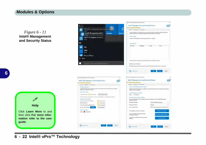
Modules & Options
6
Figure 6 - 11Intel® Management and Security Status
Help
Click Learn More to andthen click For more infor-mation refer to the userguide.
6 - 22 Intel® vPro™ Technology

Modules & Options
6
PC Camera ModuleWhen the PC Camera application is run the LED indicator to the left of the camerawill be illuminated (see Figure 1 - 2 on page 1 - 6). Note that you need to use theCamera app in Windows to take pictures and capture video. Use the Fn + F10 keycombination (see “Function/Hot Key Indicators” on page 1 - 11) to toggle powerto the PC Camera module.
2
PC Camera Module 6 - 23

Modules & Options
6
Camera App1. Make sure the PC Camera is turned on by using the Fn + F10 key combination (or
Control Center button).2. Run the Camera app from the Start menu by clicking on the Camera app icon
(you can type “camera” into the search box to find the Camera app).3. The interface displays two buttons on the right of the screen; one for photo and
one for video.
4. Simply click on the appropriate button to switch to either photo or video modes.5. You can use the buttons at the top of the screen to access the Settings and Auto/
Pro menus (for Self Timer or Exposure compensation).
Figure 6 - 12Camera App Mode
Icons
Figure 6 - 13Camera Menu
Buttons
Photo Video
6 - 24 PC Camera Module

Modules & Options
6
6. Click Settings to access the camera settings menu to make adjustments for Camera press and hold button, photo Aspect ratio, Framing grid, Time lapse, video recording frame rates and Flicker reduction.
Figure 6 - 14Camera Settings
Camera Settings
The Self Timer can be set to take Photos after 2, 5 or 10 secondsand can also be set to continue taking pictures until the camerabutton is pressed again (Photo Burst).
The Aspect Ratio can be changed to those the system supports.
You can use a Framing grid to help you line up pictures.
Time lapse can be set to keep taking photos until the camera but-ton is pressed again.
The Video recording resolution and frame rate can be set to anysupported by the system. Note that capturing high resolution vid-eo files requires a substantial amount of disk space for each file.After recording video, check the video file size (right-click the fileand select Properties) and the remaining free space on your harddisk (go to File Explorer, right-click the hard disk, and select Prop-erties). If necessary you can remove the recorded video file to aremovable medium e.g. CD, DVD or USB Flash drive.
If you need to reduce any screen flicker, change the settings inFlicker reduction to either e.g. 50Hz or 60Hz.
PC Camera Module 6 - 25

Modules & Options
6
7. With the Pro menu expanded you can access the Exposure compensation button to adjust the brightness.
Figure 6 - 15Camera Brightness
Adjustment
6 - 26 PC Camera Module

Modules & Options
6
Taking Pictures/Capturing Video1. Make sure the PC Camera is turned on by using the Fn + F10 key combination (or
Control Center button).2. Run the Camera app from the Start menu by clicking on the Camera app icon
(you can type “camera” into the search box to find the Camera app).3. Click to select either photo or video modes.4. Click the photo icon to take a picture.5. Click on the video icon to start video capture (when video capture begins a
timer will appear at the bottom of the screen).6. To stop video capture click the stop button (you can also pause the video
capture).
Figure 6 - 16Video Camera Recording in
Process
PC Camera Module 6 - 27

Modules & Options
6
7. Captured photos and videos will be saved to the Photos app stored in the Start menu (type Photos into the search box if you cannot find the app). You can also access the photos from the Camera roll icon at the bottom right of the Camera app screen.
Figure 6 - 17Photos App
(For Captured Photos & Videos)
&Camera Roll in the
Camera App
6 - 28 PC Camera Module

Modules & Options
6
Trusted Platform ModuleThe TPM security chip allows you to create and manage digital certificates for userand platform authentication. This type of security is usually administered withinlarge enterprises and organizations, and therefore requires implementation by a sys-tem administrator before users can access security features.
Individual users can use the TPM as an authentication with the fingerprint reader.
Make sure you have administrator’s rights to your computer, and have a Windowspassword enabled for full security protection. In addition Make sure you preparea removable media (e.g. a USB flash drive) to store passwords etc. before begin-ning the TPM initialization process.
Before setting up the TPM functions you must initialize the security platform.
Trusted Platform Module 6 - 29

Modules & Options
6
Enabling & Managing TPM1. Restart the computer.2. Enter the Aptio Setup Utility pressing F2 during the POST/startup.3. Use the arrow keys to select the Security menu.4. Select TPM Configuration and press Enter to access the sub-menu.5. Press Enter to access Security Device Support and select Enable.6. Press F4 to save the changes and restart the computer.7. You can now manage the TPM from Windows.
Figure 6 - 18Security Device
Support (Enabled)
6 - 30 Trusted Platform Module

Modules & Options
6
TPM Management in WindowsYou can manage your TPM settings from within Windows:
1. Go to the Control Panel.2. Click BitLocker Drive Encryption (System and Security).3. Click TPM Administration.
Figure 6 - 19BitLocker Drive
Encryption (TPM
Administration)
Trusted Platform Module 6 - 31

Modules & Options
6
4. The TPM Management window allows you to configure the TPM within Windows. As TPM is usually administered within large enterprises and organizations, your system administrator will need to assist you in managing the information here.
Figure 6 - 20Trusted Platform
Module (TPM) Management on Local Computer Administration
6 - 32 Trusted Platform Module

Modules & Options
6
TPM Actions1. Click Prepare the TPM and follow the instructions in the Wizard to prepare the
TPM (this will probably require a restart of the computer and confirmation of the setting changes after restart by pressing the appropriate F key).
2. After the restart the TPM will be prepared and you can then use the Actions menu to Turn TPM off, Change Owner Password, Clear TPM or Reset TPM Lockout.
3. A wizard will help take you through any setup steps.
Figure 6 - 21TPM Actions Menu
Trusted Platform Module 6 - 33

Modules & Options
6
BitLockerBitLocker Drive Encryption can be used in conjunction with the TPM to encryptdata on the disk. Access the Microsoft BitLocker Drive Encryption control panelapplet from the Windows control panel (System and Security).
1. Click Turn on Bit Locker.2. Follow the on-screen instructions to setup BitLocker, and make sure you have a
removable media (e.g. a USB flash drive) to store saved recovery keys etc.
Figure 6 - 22BitLocker Drive
Encryption
6 - 34 Trusted Platform Module

Modules & Options
6
3G/4G ModuleIf you have included an optional UMTS/HSPDA+ based 3G module (UniversalMobile Telecommunications System or High Speed Packet Access) module or LTE(Long Term Evolution) 4G module (see “Communication” on page D - 3 for spec-ification details) in your purchase option, you do not require a driver/applicationinstallation for Windows 10. Follow the instructions overleaf to install the USIMcard (which will be provided by your service provider), and then access the 3G/4Gnetwork in the same manner as the WLAN.
Wireless Device
Operation Aboard Aircraft
The use of any portableelectronic transmission de-vices aboard aircraft is usu-ally prohibited. Make surethe 3G/4G/WLAN/Blue-tooth module(s) are OFF ifyou are using the computeraboard aircraft. Use Air-plane Mode hot key to tog-gle Airplane Mode On/Off,and check the LED indica-tor for the power status.
Important Notice
If your purchase option includes both Wireless LAN and 3G/4G modules, then the appro-priate antennas will be installed. Note that In order to comply with FCC RF exposure com-pliance requirements, the antenna must not be co-located or operate in conjunction withany other antenna or transmitter.
Important Notice - 3G/4G & Bluetooth/Wireless LAN Modules
In order to comply with FCC regulations you should NOT operate the 3G/4G module andthe Bluetooth/Wireless LAN modules at the same time as this may disrupt radio frequency,and cause interference. When the 3G/4G module is powered on, make sure that the Blue-tooth/Wireless LAN modules are powered off.
3G/4G Module 6 - 35

Modules & Options
6
3G/4G Module USIM Card InstallationFollow the instructions below to install the USIM card (which will be supplied byyour service provider).
1. Turn off the computer, and turn it over and then remove the battery (slide latch in the direction indicated below, then slide hold latch in place and slide the bat-tery out in the direction of arrow ).
2. Insert the USIM card into the slot at the rear of the battery compartment, as illustrated below, until it clicks fully into position, and then replace the battery (see over).
Power Safety
Warning
Before you undertake anyinstallation procedures,make sure that you haveturned off the power, anddisconnected all peripher-als and cables (includingtelephone lines). It is advis-able to also remove yourbattery in order to preventaccidentally turning the ma-chine on.
USIM Card Orientation
Note that the USIM card’sreadable side (with thegold-colored contacts)should face down as illus-trated.
Figure 6 - 23Battery Removal
12
34
12
3
12
3
4
6 Cell Battery9 Cell Battery
6 - 36 3G/4G Module
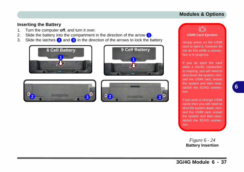
Modules & Options
6
Inserting the Battery1. Turn the computer off, and turn it over.2. Slide the battery into the compartment in the direction of the arrow .3. Slide the latches and in the direction of the arrows to lock the battery
USIM Card Ejection
Simply press on the USIMcard to eject it, however donot do this while a connec-tion is in progress.
If you do eject the cardwhile a 3G/4G connectionis ongoing, you will need toshut down the system, rein-sert the USIM card, restartthe system and then rees-tablish the 3G/4G connec-tion.
If you wish to change USIMcards then you will need toshut the system down, rein-sert the USIM card, restartthe system and then rees-tablish the 3G/4G connec-tion.
Figure 6 - 24Battery Insertion
12 3
1
2 33
1
2
6 Cell Battery 9 Cell Battery
3G/4G Module 6 - 37
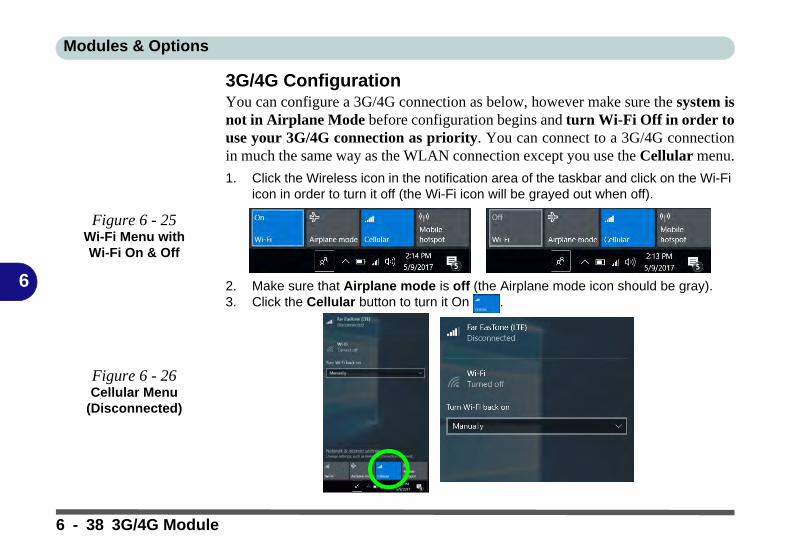
Modules & Options
6
3G/4G ConfigurationYou can configure a 3G/4G connection as below, however make sure the system isnot in Airplane Mode before configuration begins and turn Wi-Fi Off in order touse your 3G/4G connection as priority. You can connect to a 3G/4G connectionin much the same way as the WLAN connection except you use the Cellular menu.
1. Click the Wireless icon in the notification area of the taskbar and click on the Wi-Fi icon in order to turn it off (the Wi-Fi icon will be grayed out when off).
2. Make sure that Airplane mode is off (the Airplane mode icon should be gray).3. Click the Cellular button to turn it On .
Figure 6 - 25Wi-Fi Menu with Wi-Fi On & Off
Figure 6 - 26Cellular Menu
(Disconnected)
6 - 38 3G/4G Module

Modules & Options
6
4. Click Connect to connect to the cellular network manually.5. Once connected you can then access the internet, download e-mail etc. as per any
internet connection.6. Click Disconnect to drop the connection to the cellular network.7. You will need to turn your Wi-Fi on again after disconnecting.
Power Saving States & Cellular Connections
Note that if your systemgoes in to a power sav-ing state, you will needto reconnect to your cel-lular network when thesystem resumes.
Figure 6 - 27Cellular Connection
3G/4G Module 6 - 39

Modules & Options
6
8. Cellular in Network & Internet in Windows Settings will allow you to access some further cellular settings.
Figure 6 - 28Network & Internet Settings > Cellular
6 - 40 3G/4G Module

Modules & Options
6
9. Click Advanced options to access more detailed menu options.
Figure 6 - 29Cellular > Advanced
Options
3G/4G Module 6 - 41

Modules & Options
6
6 - 42

Troubleshooting
7
Chapter 7: Troubleshooting
OverviewShould you have any problems with your computer, before consulting your service representative, you may wantto try to solve the problem yourself. This chapter lists some common problems and their possible solutions. Thiscan’t anticipate every problem, but you should check here before you panic. If you don’t find the answer in thesepages, make sure you have followed the instructions carefully and observed the safety precautions in the preface.If all else fails, talk to your service representative. You should also make a record of what happened and whatremedies you tried.
Of course, if something goes wrong, it will happen at the most inconvenient time possible, so you should previewthis section just in case. If, after you’ve tried everything, and the system still won’t cooperate, try turning it offfor a few minutes and then rebooting. You will lose any unsaved data, but it may start working again. Then callyour service representative.
Overview 7 - 1

Troubleshooting
7
Basic Hints and TipsMany of the following may seem obvious but they are often the solution to a problem when your computer ap-pears not to be working.
• Power - Is the computer actually plugged into a working electrical outlet? If plugged into a power strip, make sure it is actually working. Check the LED Indicators (see “LED Indicators” on page 1 - 7) to see the computer’s power status.
• Connections - Check all the cables to make sure that there are no loose connections anywhere.
• Power Savings - Make sure that the system is not in Hibernate or Sleep mode by pressing the keys config-ured in your Power Options (see “Power-Saving States” on page 3 - 7), the Fn + F4 key combination, or power button to wake-up the system.
• Brightness - Check the brightness of the screen by pressing the Fn + F8 and F9 keys to adjust the bright-ness.
• Display Choice - Press Fn + F7 to make sure the system is not set to “external only” display.
• Boot Drive - Make sure there are no optical media and/or USB storage devices in any connected drive.
7 - 2 Basic Hints and Tips

Troubleshooting
7
Backup and General Maintenance• Always backup your important data, and keep copies of your OS and programs safe, but close to hand.
Don’t forget to note the serial numbers if you are storing them out of their original cases, e.g. in a CD wal-let.
• Run maintenance programs on your hard disk and OS as often as you can. You may schedule these pro-grams to run at times when you are not using your computer. You can use those that are provided free with your OS, or buy the more powerful dedicated programs to do so.
• Write down your passwords and keep them safe (away from your computer). This is especially important if you choose to use a Supervisor password for the BIOS (see “The Setup Utility” on page 5 - 2).
• Keep copies of vital settings files such as network, dialup settings, mail settings etc.(even if just brief notes).
Warranty
The CPU is not a user serviceable part. Opening this compartment, or accessing the CPU in any way, may violate your war-ranty.
Backup and General Maintenance 7 - 3

Troubleshooting
7
Viruses• Install an Anti-Virus program and keep the definitions file (the file which tells your program which viruses
to look for) up to date. New computer viruses are discovered daily, and some of them may seriously harm your computer and cause you to lose data. Anti-Virus programs are commercially available and the defini-tions file updates are usually downloadable directly from the internet.
• Be careful when opening e-mail from sources you don’t know. Viruses are often triggered from within e-mail attachments so take care when opening any attached file. You can configure most Anti-Virus pro-grams to check all e-mail attachments. Note: You should also beware of files from people you know as the virus may have infected an address book and been automatically forwarded without the person’s knowl-edge.
• Keep a “Bootable CD-ROM/DVD-ROM/USB storage device” (this CD/DVD/USB device provides basic information which allows you to startup your computer) handy. You may refer to your OS’s documentation for instructions on how to make one, and many Anti-Virus programs will also provide such a disk (or at least instructions on how to make one).
7 - 4 Viruses

Troubleshooting
7
Upgrading and Adding New Hardware/Software• Do not be tempted to make changes to your Windows Registry unless you are very sure of what you are
doing, otherwise you will risk severely damaging your system.
• Don’t open your computer or undertake any repair or upgrade work if you are not comfortable with what you are doing.
• Read the documentation. We can assume, since you are reading this that you are looking at the computer’s manual, but what about any new peripheral devices you have just purchased? Many problems are caused by the installation of new hardware and/or software. Always refer to the documentation of any new hardware and/or software, and pay particular attention to files entitled “READ ME” or “READ ME FIRST”.
• When installing a new device always make sure the device is powered on, and in many cases you will need to restart the computer. Always check that all the cables are correctly connected.
• Make sure you have installed the drivers for any new hardware you have installed (latest driver files are usually available to download from vendor’s websites).
Upgrading and Adding New Hardware/Software 7 - 5

Troubleshooting
7
• Thoroughly check any recent changes you made to your system as these changes may affect one or more system components, or software programs. If possible, go back and undo the change you just made and see if the problem still occurs.
• Don’t over complicate things. The less you have to deal with then the easier the source of the problem may be found; Example - if your computer has many devices plugged into its ports, and a number of programs running, then it will be difficult to determine the cause of a problem. Try disconnecting all of the devices and restarting the computer with all the peripheral devices unplugged. A process of elimination (adding and removing devices and restarting where necessary) will often find the source of a problem, although this may be time consuming.
7 - 6 Upgrading and Adding New Hardware/Software

Troubleshooting
7
Problems and Possible Solutions
Problem Possible Cause - Solution
You turned on the power but it doesn’twork.
Battery missing / incorrectly installed. Check the battery bay, make sure thebattery is present and seated properly (the design of the battery only allows it togo in one way). Make sure there’s nothing interfering with the battery contacts.
The battery LED power indicator , isblinking orange.
Low Battery. Plug in the DC power source. If the computer doesn’t start upimmediately, turn it off then on again.
You are losing battery power too quickly. The system is using too much power. If your OS has a Power Options scheme(see “Power Plans” on page 3 - 5) check its settings. You may also be using aUSB device/external device that is drawing a lot of power.
Actual battery operating time is shorterthan expected.
The battery has not been fully discharged before being recharged. Make surethe battery is fully discharged and recharge it completely before reusing (see“Battery Information” on page 3 - 16).
Power Options have been disabled. Go to the Control Panel in Windows andre-enable the options.
A peripheral device/USB device is consuming a lot of power. Turn off/removethe unused device to save power.
Problems and Possible Solutions 7 - 7

Troubleshooting
7
The computer feels too hot. Make sure the computer is properly ventilated and the Vent/Fan intakes are notblocked. If this doesn’t cool it down, put the system into Hibernate mode or turnit off for an hour. Make sure the computer isn’t sitting on a thermal surface (see“Overheating” on page 1 - 17). Make sure you’re using the correct adapter.
Make sure that your notebook is completely powered off before putting it into atravel bag (or any such container). Putting a notebook which is powered on in atravel bag may cause the Vent/Fan intakes to be blocked.
The system will not wake up from apower saving state (Sleep/Hibernate)on network activity (Wake on LAN) eventhough I have plugged in the poweredAC/DC adapter.
Wake on LAN is supported in AC mode only.
When the system enters a power saving state the plugged in AC/DC adaptershould be connected, and should remain connected, in order to allow thesystem to wake up on network activity. Unplugging the adapter, and thenplugging it back in again, will not allow the system to wake up on networkactivity.
Nothing appears on screen. The system is in a power saving mode. Toggle the sleep/resume keycombination, Fn + F4 (see “Configuring the Power Buttons” on page 3 - 9).
The screen controls need to be adjusted. Toggle the screen control keycombinations Fn + F8/F9. If you’re connected to an external monitor, make sureit’s plugged in and turned on. You should also check the monitor’s ownbrightness and contrast controls.
The computer is set for a different display. Toggle the screen display keycombination, Fn + F7. If an external monitor is connected, turn it on.
The screen saver is activated. Press any key or touch the Touchpad.
Problem Possible Cause - Solution
7 - 8 Problems and Possible Solutions

Troubleshooting
7
No image appears on the externalmonitor I have plugged in and poweredon.
You haven’t installed the video driver and configured it appropriately from theControl Panel. See Appendix C for instructions on installing and configuringthe video driver.
You forget the boot password. If you forget the password, you may have to discharge the battery of the CMOS.Contact your service representative for help.
The CD/DVD cannot be read. The CD/DVD is dirty. Clean it with a CD/DVD cleaner kit.
The CD/DVD tray will not open whenthere is a disc in the tray.
The CD/DVD is not correctly placed in the tray. Gently try to remove the discusing the eject hole (see “Loading Discs” on page 2 - 3).
The DVD regional codes can no longerbe changed.
The code has been changed the maximum 5 times. See “DVD RegionalCodes” on page 2 - 5.
My internal microphone seems to bedisabled and/or I can still hear soundfrom the speakers even though I haveplugged headphones into the headphonejack.
You have disabled “Front panel jack detection” in Connector Settings in theRealtek HD Audio Manager control panel. Go to the Realtek HD AudioManager and click the Connector Settings icon and make sure that there isno tick alongside “Front panel jack detection” and click OK.
Problem Possible Cause - Solution
Password Warning
If you choose to set a boot password, NEVER forget your password. The consequences of this could be serious. If you cannot rememberyour boot password you must contact your vendor and you may lose all of the information on your hard disk.
Problems and Possible Solutions 7 - 9

Troubleshooting
7
The sound cannot be heard or the volumeis very low.
The volume might be set too low. Check the volume control in the VolumeControl Panel in the Windows taskbar, or use the key combination Fn + F5 andF6 (see “Function/Hot Key Indicators” on page 1 - 11) to adjust.
Unwelcome numbers appear whentyping.
If the LED is lit, then Num Lock is turned ON. (see “LED Indicators” onpage 1 - 7).
The system freezes or the screen goesdark.
The system’s power saving features have timed-out. Use the AC/DC adapter,press the sleep (Fn + F4) key combination, or press the power button if no LEDsare lit.
The system never goes into a powersaving mode.
Power Options features are not enabled. Go to the Windows Power Optionsmenu and enable the features you prefer (see “Power-Saving States” onpage 3 - 7). Make sure you have enabled Hibernate mode from the controlpanel.
Problem Possible Cause - Solution
Other Keyboards
If your keyboard is damaged or you just want to make a change, you can use any standard USB keyboard. The system will detect and enableit automatically. However special functions/hot keys unique to the system’s regular keyboard may not work.
7 - 10 Problems and Possible Solutions

Troubleshooting
7
The Wireless LAN or Bluetooth modulescannot be detected.
The modules are off as the computer is in Airplane Mode. Check the LEDindicator to see if it is in Airplane Mode (see “LED Indicators” on page 1- 7). Use the Fn + F11 key combination to toggle Airplane Mode on/off (seeTable 1 - 3, on page 1 - 11).
The PC Camera module cannot bedetected.
The module is off. Press the Fn + F10 key combination in order to enable themodule (see “Function/Hot Key Indicators” on page 1 - 11). Run the cameraapplication to view the camera picture.
The Wireless LAN/Bluetooth/ PCCamera modules cannot be configured.
The driver(s) for the module(s) have not been installed. Make sure you haveinstalled the driver for the appropriate module (see the instructions for theappropriate module in “Modules & Options” on page 6 - 1).
A file cannot be copied to/from aconnected Bluetooth device.
The transfer of data between the computer and a Bluetooth enabled device issupported in one direction only (simultaneous data transfer is notsupported). If you are copying a file from your computer to a Bluetooth enableddevice, you will not be able to copy a file from the device to your computer untilthe file transfer process from the computer has been completed.
The Bluetooth module is off afterresuming from Sleep.
The Bluetooth module’s default state will be off after resuming from the Sleeppower-saving state. Use the key combination (Fn + F12) to power on theBluetooth module after the computer resumes from Sleep.
I am sliding my finger up and down on theright side of the Touchpad to scroll aWindow and the Touchpad does notrespond.
There are different Touchpad versions available on this computer, and thisversion requires tapping/holding to scroll. Either tap repeatedly, or hold thefinger down, at the top or bottom right of the Touchpad (depending on thescrolling direction required) to scroll the window.
Problem Possible Cause - Solution
Problems and Possible Solutions 7 - 11

Troubleshooting
7
The fingerprint reader has problemsscanning fingers.
When fingers are wet or sweaty the software application may have difficultyreading a scanned finger. Make sure your fingers are clean and dry whenattempting to scan them across the sensor for detection.
The computer is off (or in Sleep Mode) butpowered by the AC/DC adapter plugged into a working outlet, or by battery with acapacity above 20%. I have plugged adevice into the powered USB port inorder to charge it, but the device is notcharging.
The port is not powered on. Toggle power to the port using the Fn + powerbutton combination.
This function may not work with certain external USB compliant devices (checkyour device’s documentation). If this is the case, power the computer on andconnect the external USB device in order to charge it.
Note that this function is designed to help charge USB compliant devices, butis not designed to allow their operation.
I have changed or replaced a WLANmodule and have received an errormessage.
See “Intel® Rapid Storage Technology” on page 6 - 19.
Problem Possible Cause - Solution
7 - 12 Problems and Possible Solutions

Troubleshooting
7
I have used Update Driver in DeviceManager (Unknown device > OtherDevices) to try and install the AirplaneMode driver. Windows encountered aproblem in attempting to update the driver,and a yellow exclamation mark appearsin Device Manager against the Unknowndevice.
It is very important that the drivers are installed in the order indicated in Chapter4 (which is the numbered installation order on the Device Drivers & Utilities +User’s Manual disc). This issue can occur when drivers are manually installed,and not in the correct order.
If you have attempted to Update Driver from the Device Manager control paneland have encountered problems, then use the method below to correct this:
To correct this problem:
1. Go to the Programs and Features (Programs) control panel in Windows.
2. Select any installed Airplane Mode driver item (e.g. Insyde Airplane Mode HID Mini-Driver), and click Uninstall/Change to uninstall the current driver.
3. Restart the computer.4. Insert the Device Drivers & Utilities + User’s Manual disc and click
Install Drivers (button).5. Double-click the Airplane Driver item in the menu.6. Follow the instructions to install the correct driver (you will need to
restart the computer as part of the installation process).
Problem Possible Cause - Solution
Problems and Possible Solutions 7 - 13

Troubleshooting
7
When using a Bluetooth headset theaudio appears to be mono and notstereo.
This is a common issue with Bluetooth headsets. To resolve this issue do thefollowing (you will need to repeat this procedure after every boot up, restart,or when the system resumes from hibernation):
1. Go to the Devices & Printers control panel in Windows.2. Double-click the Bluetooth headset.3. Click Connect to complete the stereo connection.OR1. Go to the Sound control panel in Windows.2. Right-click (in the Playback tab) the Bluetooth Stereo Audio device
(the default device is Headset).3. Click Connect to complete the stereo connection.
Problem Possible Cause - Solution
7 - 14 Problems and Possible Solutions

Interface (Ports & Jacks)
A
Appendix A: Interface (Ports & Jacks)
OverviewThe following chapter will give a quick description of the interface (ports & jacks) which allow your computerto communicate with external devices, connect to the internet etc.
Interface (Ports & Jacks) A - 1

Interface (Ports & Jacks)
A
Notebook Ports and JacksItem Description
2-in-1 Audio Jack (Headphone-Out Jack/SPDIF Jack)
This is a combination headphone/S/PDIF Jack. Headphones or speakers can beconnected through this jack. Note: Set your system’s volume to a reduced level beforeconnecting to this jack.
As a S/PDIF (Sony/Philips Digital Interface Format) Out Jack, it allows you toconnect your DVD-capable PC to a Dolby AC-3 compatible receiver for “5.1” or ‘dts’surround sound.
Card Reader Port The card reader allows you to use some of the latest digital storage cards. Push thecard into the slot and it will appear as a removable device.
• MMC (MultiMedia Card) / RSMMC• SD (Secure Digital) / Mini SD / SDHC / SDXC
DC-In Jack Plug the supplied AC/DC adapter into this jack to power your computer.
External Monitor (VGA) Port This port allows you to connect an external monitor, or Flat Panel Display, to get dualvideo or simultaneous display on the LCD and external monitor/FPD.
SPDIF
A - 2 Interface (Ports & Jacks)

Interface (Ports & Jacks)
A
HDMI-Out Port The HDMI-Out (High-Definition Multimedia Interface) is an audio/video connectorinterface for transmitting un compressed digital streams. This allows you to connect anexternal monitor, TV or Flat Panel Display etc. as a display device by means of a HDMIcable. Note that HDMI carries both audio and video signals.
Microphone-In Jack Plug an external microphone in to this jack to record on your computer.
RJ-45 LAN Jack This port supports LAN (Network) functions.Note: Broadband (e.g. ADSL) modems usually connect to the LAN port.
Security Lock Slot To prevent possible theft, a Kensington-type lock can be attached to this slot. Locks canbe purchased at any computer store.
Smart Card Reader The Smart Card reader reads pocket-sized Smart Cards, chip cards, or integratedcircuit cards (ICC) with embedded integrated circuits. Smart Cards can be used forsecurity identification, authentication, data storage and application processing withinlarge organizations.
Item Description
Interface (Ports & Jacks) A - 3

Interface (Ports & Jacks)
A
USB 2.0/1.1 Ports*/USB 3.0 Ports These USB 2.0 compatible ports (USB 2.0 is fully USB 1.1 compliant) are for low-speedperipherals such as keyboards, mice or scanners, and for high-speed peripherals suchas external HDDs, digital video cameras or high-speed scanners etc. Devices can beplugged into the computer, and unplugged from the computer, without the need to turnthe system off (if the power rating of your USB device is 500mA or above, make sureyou use the power supply which comes with the device).
The USB 3.0 ports are denoted by their blue color; USB 2.0 ports are coloredblack. USB 3.0 will transfer data much faster than USB 2.0, and is backwards-compatible with USB 2.0.
*Note: The powered USB 3.0 port (see “System Map: Left View” on page 1 - 14)may be toggled on /off by means of the Fn + Power Button key combination. When thepowered USB port is on it will supply power when the system is off but still powered bythe AC/DC adapter plugged into a working outlet, or powered by the battery with a ca-pacity level above 20% (this may not work with certain devices - see page 7 - 12).
Note: This function is designed to help charge USB compliant devices, but is not de-signed to allow their operation.
Item Description
3.0
A - 4 Interface (Ports & Jacks)

Control Center
B
Appendix B: Control CenterOverviewThe following chapter will give a quick description of the functions of the Control Center. The Control Centergives quick access to frequently used controls, power management features and enables you to quickly turn mod-ules on/off. Click the Control Center icons to toggle the appropriate function, or hold the mouse button downand move the dial control where applicable. Certain functions will automatically be adjusted when a power modeis selected. The Control Center in Windows 10 works under the Desktop App and not under the Start screen.
Figure B - 1 - Control Center
Control Center Access
To run the Control Centerpress the Fn + Esc key com-bination, or double-click theicon in the notificationarea of the taskbar.
Close the Control Center byclicking the close icon inthe top right of the panel(move the cursor onto thetop right corner of the panel to highlight it).
Control Center B - 1
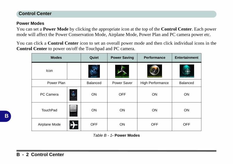
Control Center
B
Power ModesYou can set a Power Mode by clicking the appropriate icon at the top of the Control Center. Each powermode will affect the Power Conservation Mode, Airplane Mode, Power Plan and PC camera power etc.
You can click a Control Center icon to set an overall power mode and then click individual icons in theControl Center to power on/off the Touchpad and PC camera.
Table B - 1- Power Modes
Modes Quiet Power Saving Performance Entertainment
Icon
Power Plan Balanced Power Saver High Performance Balanced
PC Camera ON OFF ON ON
TouchPad ON ON ON ON
Airplane Mode OFF ON OFF OFF
B - 2 Control Center

Control Center
B
Control Center MenusThe Control Center contains 2 menu headings (System Program and Device) under the Power Modes.Click the menu headings and then click any of the buttons outlined on the following pages.
Figure B - 2 - Control Center Menus
Control Center B - 3

Control Center
B
Power Status (System Program) /
The Power Status icon will show whether you are currently powered by the battery, or by the AC/DC adapterplugged in to a working power outlet. The power status bar will show the current battery charge state.
CPU Temperature (System Program)
The temperature icon will display the current CPU temperature. Click the icon to have the temperature dis-played in either degrees Celsius or Fahrenheit.
Brightness (System Program) The Brightness icon will show the current screen brightness level. You can use the slider to adjust the screenbrightness or the Fn + F8/F9 key combinations, or use the Fn+ F2 key combination to turn off the LED backlight(press any key to turn it on again).
Volume (System Program)The Volume icon will show the current volume level. You can use the slider to adjust the Volume or the Fn +F5/F6 key combinations, or use the Fn+ F3 key combination to mute the volume.
Fan Speed (System Program)You can set the fan speed to Maximum (full power), Automatic or Custom from this menu item. The fan speedwill adjust itself automatically to control the heat of the CPU. However you can adjust the setting to maximumif you prefer. Select Custom and click on the sliders to adjust the settings to your preference, however these set-tings can be overridden by the system, as a safety precaution, if it requires heavier use of the fan (see over).
B - 4 Control Center
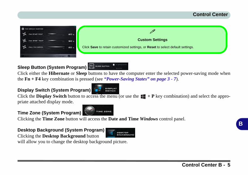
Control Center
B
Sleep Button (System Program) Click either the Hibernate or Sleep buttons to have the computer enter the selected power-saving mode whenthe Fn + F4 key combination is pressed (see “Power-Saving States” on page 3 - 7).
Display Switch (System Program) Click the Display Switch button to access the menu (or use the + P key combination) and select the appro-priate attached display mode.
Time Zone (System Program) Clicking the Time Zone button will access the Date and Time Windows control panel.
Desktop Background (System Program) Clicking the Desktop Background button will allow you to change the desktop background picture.
Custom Settings
Click Save to retain customized settings, or Reset to select default settings.
Control Center B - 5

Control Center
B
Backlight Keyboard (Device) Click the numbers under the Backlight Keyboard icon to adjust the brightness of the keyboard backlight LED.
TouchPad/PC Camera (Device) Click either of these buttons to toggle the TouchPad or camera module’s power status. The icon will appeardimmed when it is off. Note that the power status of the camera module is also effected by the Power Modeselected (see Table B - 1, on page B - 2).
Docking (Device) /
Click the Docking (Enable/Disable) button to prepare the system for docking/undocking.
Caps Lock/Scroll Lock/ Number Lock/Airplane ModeClick the button to toggle the appropriate lock mode and Airplane Mode.
B - 6 Control Center

Video Driver Controls
C
Appendix C: Video Driver ControlsThe basic settings for configuring the LCD are outlined in “Video Features” onpage 1 - 29.
Video Driver InstallationMake sure you install the drivers in the order indicated in Table 4 - 1, on page 4 - 4.
1. Insert the Device Drivers & Utilities + User’s Manual disc and click Install Drivers (button).
1. Click 2.Install VGA Driver > Yes.2. Click Next > Yes > Next > Next.3. Click Finish to restart the computer.
Note: After installing the video driver go to the Display/Display Settings controlpanel to adjust the video settings to the highest resolution.
Dynamic Video Memory TechnologyIntel® DVMT automatically and dynamically allocates as much system memory(RAM) as needed to the integrated video system (the video driver must be in-stalled). DVMT returns whatever memory is no longer needed to the operating sys-tem.
Video Card Options
Note that card types,specifications and driv-ers are subject to contin-ual updates andchanges. Check withyour distributor/supplierfor the latest details onvideo cards supported.
DVMT Notes
DVMT is not local videomemory.
DVMT will not functionin MS-DOS. DOS usesthe legacy memory indi-cated.
Video Driver Installation C - 1

Video Driver Controls
C
Intel® HD Graphics Control PanelAdvanced video configuration options are provided by the Intel® HD Control Pan-el. To access the control panel see below and overleaf:
1. Right-click the Desktop and select Intel(R) Graphics Settings from the menu.
OR2. Click the icon in the notification area of the Desktop taskbar and select Intel(R)
Graphics Settings from the menu.
Figure C - 1Right-Click Desktop
(Intel Graphics
Settings)
Figure C - 2Taskbar Notification
Area Icon Menu
C - 2 Intel® HD Graphics Control Panel

Video Driver Controls
C
OR3. Double-click the Intel(R) HD Graphics control panel in the Windows Control
Panel.
Figure C - 3 Control Panel
Intel® Graphics
Settings
Intel® HD Graphics Control Panel C - 3

Video Driver Controls
C
You may make changes to any of the graphics properties by clicking the appropriatemenu panel and adjusting the settings from the menus.
Home
Click the Home button toreturn to the main menuscreen in any of the sub-menu screens.
Figure C - 4Intel® HD Graphics
Control Panel
C - 4 Intel® HD Graphics Control Panel

Video Driver Controls
C
DisplayClick either Display Settings or Color Settings to make display adjustments, in-cluding configuration for any attached external displays.
Multiple Display
At least one other dis-play must be attached inorder to view multipledisplay selection op-tions.
Figure C - 5Intel® HD Graphics
Control Panel
Display
Intel® HD Graphics Control Panel C - 5
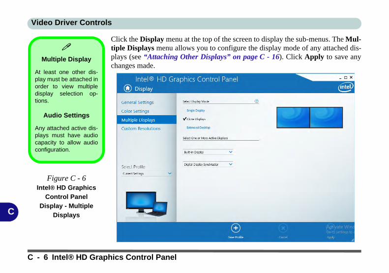
Video Driver Controls
C
Click the Display menu at the top of the screen to display the sub-menus. The Mul-tiple Displays menu allows you to configure the display mode of any attached dis-plays (see “Attaching Other Displays” on page C - 16). Click Apply to save anychanges made.
Multiple Display
At least one other dis-play must be attached inorder to view multipledisplay selection op-tions.
Audio Settings
Any attached active dis-plays must have audiocapacity to allow audioconfiguration.
Figure C - 6Intel® HD Graphics
Control Panel
Display - Multiple
Displays
C - 6 Intel® HD Graphics Control Panel

Video Driver Controls
C
The Custom Resolutions sub-menu allows you to adjust the display (or any at-tached display) to any width, height, refresh rate, color depth and underscan percent-age of your choice. Note that incorrect settings can cause system instability and evenpossible component damage, so this is adjusted at your own risk.
Figure C - 7Intel® HD Graphics
Control Panel
Display Settings -
Custom
Resolutions
Intel® HD Graphics Control Panel C - 7

Video Driver Controls
C
3DThis menu allows you to choose how 3D images are displayed. Performance givesthe smoothest motion of images, Quality displays the most detail, Balanced Modeprovides better computer performance with good quality and Custom allows you toconfigure the Anisotropic Filtering and Vertical Sync and features to your prefer-ences. Click Apply to save changes.
Figure C - 8Intel® HD Graphics
Control Panel 3D
C - 8 Intel® HD Graphics Control Panel

Video Driver Controls
C
Options and SupportHot Key Manager in Options and Support allows you to create hot keys for open-ing the application, rotating the display, scaling etc. Click Apply to save changes.
Figure C - 9Intel® HD Graphics
Control Panel
Options and
Support
Intel® HD Graphics Control Panel C - 9

Video Driver Controls
C
Click the Options menu at the top of the screen to display the sub-menus. The In-formation Center provides details on System Information, the Built-In Displayand any attached displays.
Preferences
Go to the Preferencessub-menu in Options toconfigure the preferencesfor the Intel® HD GraphicsControl Panel.
Make sure you click En-able under Tray Icon todisplay the Intel® HDGraphics Control Panelicon in the notification areaof the taskbar (as below).
Figure C - 10Intel® HD Graphics
Control Panel
Options -
Information Center
C - 10 Intel® HD Graphics Control Panel

Video Driver Controls
C
VideoThe Video menu allows you to brighten or darken movies, or to switch to vivid col-ors. The Preview image will display a sample image using the current settings. Youcan Save Profile and name the Profile to recall the settings at any time. Click Applyto save changes (select Color Enhancement, Image Enhancement, Image Scalingor Gamut Mapping from the menu).
Figure C - 11Intel® HD Graphics
Control Panel -
Video
(Color
Enhancement)
Intel® HD Graphics Control Panel C - 11

Video Driver Controls
C
Click the Video menu at the top of the screen to display the sub-menus.The ImageEnhancement menu allows you to adjust the Sharpness, Skin Tone Enhancementin the Basic menu, and Noise Reduction, Contrast Enhancement and Film ModeDetection in the Advanced menu. Click Apply to save changes.
Figure C - 12Intel® HD Graphics
Control Panel - Video
(Image
Enhancement Basic)
C - 12 Intel® HD Graphics Control Panel

Video Driver Controls
C
Enable Image Scaling to use the sliders to adjust the scaling.
Figure C - 13Intel® HD Graphics
Control Panel Video
Image Scaling
Intel® HD Graphics Control Panel C - 13

Video Driver Controls
C
ProfilesYou can select one of the preset profiles (Brighten Video, Darken Video and En-hance Video Colors) from the menu on the left. Alternatively you can go throughthe menus to make adjustments to your preferences for Display, Color, Video, 3D,Options and Support and Power (tick any boxes for the settings required), and thenSave the settings to a profile (which may be imported or exported).
Figure C - 14Intel® HD Graphics
Control Panel -
Profiles
C - 14 Intel® HD Graphics Control Panel

Video Driver Controls
C
Display Devices & OptionsNote that you can use external displays connected to the HDMI-Out port and/or ex-ternal monitor port. See your display device manual to see which formats are sup-ported.
Display Mode Description
Single DisplayOne of the connected displays is used as the display device (PC screen only or Second screen only).
Clone/DuplicateBoth connected displays output the same view and may be configured independently
Extended / Extend Both connected displays are treated as separate devices, and act as a virtual desktop
4K2K Videos on 4K2K
External Displays
Note you may experi-ence some video lagwhen playing 4K2K vid-eos on an attached4K2K external display.
Table C - 1Display Modes
Attaching Displays
When you first attach an external display you may find that the desktop does not occupythe full screen area. Use either the display’s auto adjust/configure controls, or the Intel(R)HD Graphics Control Panel to configure the full screen display.
Display Devices & Options C - 15

Video Driver Controls
C
Attaching Other DisplaysTo Clone Displays:1. Attach your external display to the HDMI-Out port/external monitor port, and turn it on.2. Go to the Intel(R) HD Graphics Control Panel control panel and click Display >
Multiple Displays (sub-menu).3. Click Clone from the Select Display Mode menu.4. Click Apply, and OK to confirm the settings change.5. Select the displays from the Select One or More Active Displays menu.
Multiple Display
At least one other dis-play must be attached inorder to view MultipleDisplay selection op-tions.
Figure C - 15 Display > Multiple
Displays (Clone)
C - 16 Attaching Other Displays

Video Driver Controls
C
To Enable Extended Mode:1. Attach your external display to the HDMI-Out port/external monitor port, and turn it on.2. Go to the Intel(R) HD Graphics Control Panel control panel and click Display >
Multiple Displays (sub-menu).3. Click Extended from the Select Display Mode menu.4. Click Apply, and OK to confirm the settings change.
Display Settings
Extended Desktop
You can have differentColors, Screen Areaand Monitor RefreshRates for each displaydevice provided yourmonitor can supportthem.
You can drag the moni-tor icons to match thephysical layout of yourdisplays. Icons and pro-grams may also bedragged between thedisplays.
Figure C - 16
Display > Multiple
Displays (Extended)Click the appropriate monitor icon and drag it to match the physical arrange-ment you wish to use (e.g. the secondary display may be extended left/right/above/below the primary display).
Attaching Other Displays C - 17

Video Driver Controls
C
Configure Other Displays Using ProjectYou can configure attached displays from Project.
1. Attach your display to the appropriate port, and turn it on.2. Press the + P key combination.3. Click on any one of the options from the menu to select PC screen only,
Duplicate, Extend or Second screen only.4. You can also click Connect to a wireless display at the bottom of the Project
screen and follow the steps to connect to any wireless enabled display.
Figure C - 17Project
C - 18 Configure Other Displays Using Project

Video Driver Controls
C
Configuring an External Display In WindowsThe System Control Panel in Settings may also be used to configure displays.
1. Attach your external display to the appropriate port, and turn it on.2. Click the Start Menu and click Settings > System (or right-click the desktop and
select Display Settings).3. You can change Duplicate, Extend or choose to display on 1 screen only.4. Click Apply to save any changes made.5. Click Advanced display settings to access further options.
Figure C - 18System > Display
You can configure attached displays from Project. C - 19

Video Driver Controls
C
HDMI Audio ConfigurationHDMI (High-Definition Multimedia Interface) carries both audio and video signals.In some cases it will be necessary to go to the Sound control panel and manuallyconfigure the HDMI audio output as per the instructions below.
1. Go to the Sound control panel.2. Click Playback (tab)3. The playback device will be selected.4. You may need to select the audio device and click Set Default (button).5. Double-click the device to access the control panel tabs.
Volume Adjustment
The sound volume levelcan be clicking using thevolume control icon in the notification areaof the taskbar.
Figure C - 19Sound - HDMI
Device (set Default)
C - 20 HDMI Audio Configuration

Video Driver Controls
C
6. Adjust the HDMI settings from the control panel tabs.7. Click OK to close the Sound control panel.
Figure C - 20HDMI Device
Properties
HDMI Audio Configuration C - 21

Video Driver Controls
C
HDMI Notes• Connect a device with HDMI support to the HDMI-Out port BEFORE attempt-
ing to play audio/video sources through the device.• To play audio sources through your external display’s (TV or LCD) speakers
you will need to go to the audio configuration control panel on the display and configure the audio input accordingly (see your display device manual).
HDMI Video Configuration1. Connect an HDMI cable from the HDMI-Out port to your external display.2. Configure your external display as per the instructions in “Attaching Other
Displays” on page C - 16.3. Set up your external display (TV or LCD) for HDMI input (see your display device
manual).4. You can now play video/audio sources through your external display.
Other Applications
If you are using a thirdparty application to playDVDs etc. from any at-tached DVD device,you will need to consultthe application’s docu-mentation to see theappropriate audio con-figuration (the applica-tion must support digitalto analog translation).
C - 22 HDMI Audio Configuration

Video Driver Controls
C
Wireless DisplayWireless Display uses your Wireless LAN module/WLAN Bluetooth Combo mod-ule (you need to make sure that your video adapter/display device is compatiblewith your particular WLAN/Combo module) in conjunction with a compatiblevideo adapter/display device (purchased separately) to allow you to display thecontents of the notebook display on another display (e.g. HDTV), without the needto have cables stretching across a room.
You can use the wireless display to play games, browse the internet, display videosor photo slide shows on your TV/external display without using HDMI or A/V ca-bles.
Before configuring Wireless Display you will need to set up your compatibleadapter with your display/speakers. Connect the adapter using an HDMI or A/V ca-ble and turn on the display (or in the case of speakers connect them to the wirelessspeaker adapter with the cables provided with the adapter), and then set the displayto the appropriate input channel (see the documentation supplied with your compat-ible adapter/display for full details).
Compatible
Adapters
For a list of compatibleadapters check the vid-eo adapter/display de-vice documentation, orwith your distributor/supplier.
HDMI Audio Configuration C - 23
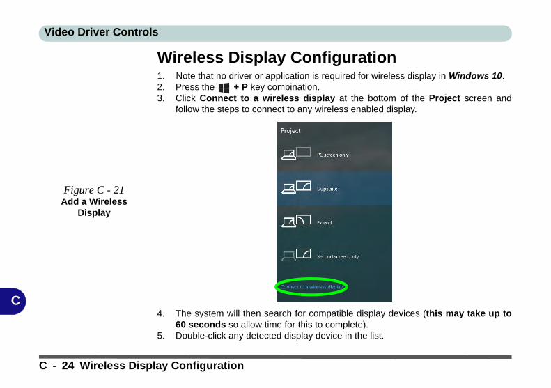
Video Driver Controls
C
Wireless Display Configuration1. Note that no driver or application is required for wireless display in Windows 10.2. Press the + P key combination.3. Click Connect to a wireless display at the bottom of the Project screen and
follow the steps to connect to any wireless enabled display.
4. The system will then search for compatible display devices (this may take up to60 seconds so allow time for this to complete).
5. Double-click any detected display device in the list.
Figure C - 21Add a Wireless
Display
C - 24 Wireless Display Configuration

Video Driver Controls
C
6. You may then need to input a pin number for the device to which you are connecting and click Next.
7. The display will then connect (for specific settings for your display see the documentation supplied with your compatible adapter/display for full details).
8. Go to the Project menu and click Disconnect to temporarily disconnect from the wireless display.
9. To permanently disconnect from the display (you will need to go back through the connection process again) you can select it in Devices and click Remove Device > Yes.
Wireless Display Configuration C - 25

Video Driver Controls
C
C - 26

Specifications
D
Appendix D: Specifications
Latest Specification Information
The specifications listed in this Appendix are correct at the time of going to press. Certain items (particularly processor types/speeds and CD/DVD device types) may be changed, updated or delayed due to the manufacturer's release schedule. Checkwith your distributor/supplier for details.
Note that this computer model series may support a range of CPUs and/or video adapters.
To find out which CPU is installed on your system go to the Start menu and select Settings, and then select System andclick About. This will also provide information on the amount of Installed RAM etc.
To get information on your system’s video adapter go to the Start menu and select Settings, and then select System andclick Display> Advanced display settings > Display adapter properties.
Specifications D - 1

Specifications
D
Core Logic
For Model A:Intel® Q170 Chipset
For Model B:Intel® H170 Chipset
Display
15.6” / 39.62cm 16:9 FHD (1920 * 1080), HD (1366 * 768) Panel (3.8mm thick)
Memory
Dual Channel DDR3L
Two 204 Pin SO-DIMM sockets supporting DDR3L 1600MHz(real operational frequency depends on the FSB of the processor)
Memory Expandable up to 16GB (using 2GB / 4GB / 8GB SO-DIMM Modules)
Storage
One Changeable 2.5" / 7 mm (h) HDD/SSD with SATA (Serial) Interface
One Changeable 9.5 mm(h) Super Multi Optical Device Drive with SATA Interface (Factory Option)
One M.2 SSD 2280, SATA/PCIe Gen 3*4 Interface (Factory Option)
Audio
High Definition Audio InterfaceS/PDIF Digital Output (S/PDIF)Built-In Microphone2 * Built-In 2W Speakers
SO-DIMM Memory Types
All SO-DIMM memory modules installed in thesystem should be identical (the same size andbrand) in order to prevent unexpected systembehavior.
Do not mix SO-DIMM memory module sizesand brands otherwise unexpected system prob-lems may occur.
Keyboard & Pointing Device
Full Size Isolated Keyboard With Numeric Pad
Full Size Isolated White Illuminated Keyboard with Numeric Keypad (Factory Option)
Built-in Touchpad with Multi-Gesture and Scrolling Functionality
Interface
Thee USB 3.0 Ports (Including 1 ACDC Powered USB Port)One USB 2.0 PortOne HDMI™ Out Port (with HDCP)One External Monitor PortOne 2-In-1 Audio Jack (Headphone Out / S/PDIF Out)One Microphone-In JackOne RJ-45 LAN JackOne DC-In JackOne Docking Port (With Hot Plug Functionality)
D - 2 Specifications

Specifications
D
Card Reader
Embedded Multi-In-1 Push-Push Card Reader - MMC/ RS MMC- SD/ Mini SD / SDHC/ SDXCNote: Some of these cards require PC adapters usually supplied with the cards.
Slot
One ExpressCard™ (54/34) Slot
One Smart Card Reader Slot (Factory Option)
Three M.2 Card Slots:================================Slot 1 for M.2 2230 Card WLAN Combo Module with PCIe & USB Interfaces
Slot 2 for M.2 2280 Card SSD (Solid State Drive) with SATA/PCIe Gen 3*4 Interface
Slot 3 for M.2 3042 LTE/HSPA+ 3G or 4G Module with USB Interface (Factory Option)
Communication
Built-In Intel® 10/100/1000Mb Base-TX Ethernet LAN
Intel® Dual Band Wireless-AC 8260(2*2 802.11 a/c) WLAN + Bluetooth M.22230 Combo Module (Factory Option)
Intel® Dual Band Wireless-AC 8265(2*2 802.11 a/c) WLAN + Bluetooth M.22230 Combo Module (Factory Option)
Intel® Dual Band Wireless-AC 3168(1*1 802.11 a/c) WLAN + Bluetooth M.22230 Combo Module (Factory Option)
*UTMS/HSPA+ M.2 3042 Card Module with USB Interface (Factory Option)OR4G LTE M.2 3042 Card Module with USB Interface (Factory Option)
*Note that UMTS modes CAN NOT be used in North America
1.0M HD Video Camera Module with USB interface
For Model B Only:Intel® Wireless-N 7265 (2*2 802.11 b/g/n)WLAN + Bluetooth M.2 2230 Combo Mod-ule (Factory Option)
Intel® Dual Band Wireless-AC 3165(1*1 802.11 a/c) WLAN + Bluetooth M.22230 Combo Module (Factory Option)
Power
Full Range AC/DC Adapter AC input 100 - 240V, 50 - 60Hz, DC Output 19V, 3.42A (65 Watts)
Built-In 6 Cell Smart Lithium Ion Battery Pack 62WH
Built-In 9 Cell Smart Lithium Ion Battery Pack 93WH
Security
Security (Kensington® Type) Lock SlotBIOS PasswordFingerprint Reader ModuleTrusted Platform Module 2.0Intel PTT for Systems Without TPM HardwareFor Model A Only:Intel® vPro Support
Specifications D - 3

Specifications
D
Security (Kensington® Type) Lock SlotBIOS PasswordFingerprint Reader ModuleTrusted Platform Module 2.0Intel PTT for Systems Without TPM HardwareFor Model A Only:Intel® vPro Support
Design Features
All USB / Card Reader / ExpressCard / Smart Card ports/slots can be switched on/off in the BIOS
Rubber Painted Style Finish
LCD Panel can be opened to 180 degree angle (with 6 Cell Battery and if system is not docked)
Shipping Mode
Operating System
Windows® 10 (64-bit)
BIOS
SPI Flash ROM - Total 128MbAMI BIOS
Power Management
Supports Wake on LAN by AC mode onlySupports Wake on USBSupports Wake on RTC alarm (S4) by AC mode only
Indicators
Power/Suspend, Battery, HDD/ODD, Airplane Mode, Num Lock, Caps Lock, Scroll Lock, Camera (on module)
Environmental Spec
TemperatureOperating: 5°C - 35°CNon-Operating: -20°C - 60°CRelative HumidityOperating: 20% - 80%Non-Operating: 10% - 90%
Dimensions & Weight
382mm(w) * 259.5 mm(d) * 32.95 mm(h)
2.4kg Barebone System* with 62WH Battery*A barebone system does not include the HDD, RAM, adapter, power cord and factory option modules (weight tolerance within +/- 5%).
D - 4 Specifications

Docking Station Guide
Do
cking
Statio
n
Appendix E: Docking Station Guide
OverviewThe docking station provides your computer with an easy connectable desktop environment when portability isnot required. This allows for easy connections to external displays, USB devices (with a full range of extra USBports), audio devices and provides a battery charging facility.
CompatibilityNote that this docking station is compatible with particular computer models with the appropriate docking con-nector only. Attempting to dock the computer to an incompatible docking system will result in an error message(in this case immediately separate the computer from the docking station). Please contact your distributor/sup-plier for full details.
Overview E - 1

Docking Station Guide
Do
cking
Statio
n
Computer and Docking StationThe computer may hot or cold dock/undock with the docking station, i.e. the computer may be powered on (hotdocking/undocking) or powered off (cold docking/undocking) when docking or undocking. However if you in-tend to hot dock/undock the system then make sure that the hot key driver, provided on the computer’s DeviceDrivers & Utilities + User’s Manual disc, is installed.
Docked System PowerThe system power for a docked unit should be provided only by the docking station’s AC/DC adapter pluggedin to the DC-In jack at the rear of the docking station (make sure the computer’s AC/DC adapter is not usedat any time when the computer is docked). Follow the instructions on the next pages to safely dock and undockyour computer with the docking station.
Hot Docking/Hot Undocking & Power Saving Modes
If the computer is in a power-saving state (Sleep or Hibernate), or is resuming from a power saving state, do not attempt tohot dock or hot undock the system.
Moving the Docking StationNote that if the notebook is docked with the docking station, do not attempt to move the docked unit in order to avoid losingconnection. If you wish to move the docking station, then make sure you undock the notebook from the docking station beforedoing so.
E - 2 Computer and Docking Station

Docking Station Guide
Do
cking
Statio
n
System Map: Front View Figure E - 1System Map Front
1. Power Button LED2. Backup Button (if a
Hard Disk is installed in the Device Bay)
3. Lock Switch4. Notebook Eject
Latch5. Notebook
Placeholder6. Retaining Pins7. Docking Connector8. Eject Pins
2 1
78
3
5
8
Backup Button
Note that when the backup button is used to backup the computer’s hard disk/files to thedocking station, in conjunction with the backup application, if a hard disk is installed in thedocking station’s bay.
4
6 6
System Map: Front View E - 3

Docking Station Guide
Do
cking
Statio
n
System Map: Rear ViewFigure E - 2System Map Rear
1. Security Lock Slot2. USB 3.0 Port3. DVI-D Out Port4. HDMI-Out Port5. External Monitor
Port6. RS232 (Serial)
COM Port7. RJ-45 LAN Jack8. DC-In Jack9. Headphone Jack10. Microphone Jack11. S/PDIF-Out Jack12. USB 2.0 Ports
1 311 12
2 4 59
6 710
LAN Jack & Docking
Note that when the computer is docked with the docking station, the notebook’s LAN Jackcan no longer be used as the network jack. When the system is docked use the docking sta-tion’s LAN jack as the network jack.
8
1 2 34 5 6
7 8
11 129 10 12 12
E - 4 System Map: Rear View
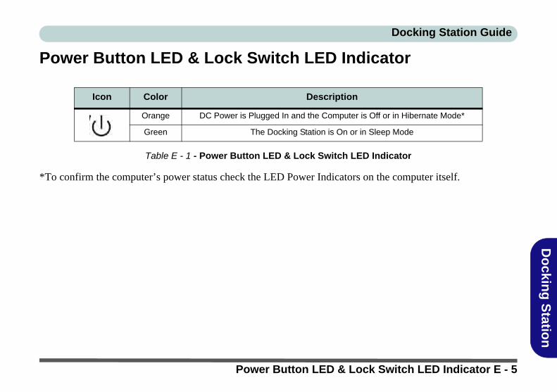
Docking Station Guide
Do
cking
Statio
n
Power Button LED & Lock Switch LED Indicator
Table E - 1 - Power Button LED & Lock Switch LED Indicator
*To confirm the computer’s power status check the LED Power Indicators on the computer itself.
Icon Color Description
Orange DC Power is Plugged In and the Computer is Off or in Hibernate Mode*
Green The Docking Station is On or in Sleep Mode
Power Button LED & Lock Switch LED Indicator E - 5

Docking Station Guide
Do
cking
Statio
n
System Map: Left & Right ViewsFigure E - 3System Map
Left & Right Views
1. Bay with HDD or Dummy CaddyOR
2. Bay with Optical Device Drive (DVD)
3. Powered USB 3.0 Port
4. USB 3.0 Ports
1
2
3 4 4
USB Port Power
Note that power to the notebook computer and docking station’s USB ports may be enabled/disabled in the notebook computer’s BIOS settings (see the BIOS guide in Chapter 5 of thenotebook’s user manual).
E - 6 System Map: Left & Right Views

Docking Station Guide
Do
cking
Statio
n
Cold Docking the Computer to the Docking Station1. Remove all packing materials and place the docking station on a stable surface.2. Securely attach any peripherals you want to use with the docking station (e.g. keyboard and mouse) to their
ports.3. Attach the AC/DC adapter to the DC-In jack at the rear of the docking station, and then plug the AC power cord
into an outlet, and connect the AC power cord to the AC/DC adapter.4. The power button LED on the docking station will be orange.
Figure E - 4 - Docking Station with AC/DC Adapter Plugged
1
1
Cold Docking the Computer to the Docking Station E - 7

Docking Station Guide
Do
cking
Statio
n
5. Make sure the computer’s hot key driver is installed (especially if you intend to hot dock the system).6. Remove the AC/DC adapter from the notebook computer and then close the computer’s lid/LCD and turn it over
(if you are using the optional 9 cell battery make sure you remove the battery before attempting to dock the computer with the docking station).
7. Slide the notebook computer’s docking port cover latch in the direction of the arrow at point to open the cover (failure to open the cover of the docking port before connecting the computer to the docking station may result in irreparable damage to the connector on the docking station).
Figure E - 5 - Opening the Docking Port
2
Docking Port Cover
Make sure you keep the cover closed when the computer is not docked in the station. This willhelp prevent foreign objects and/or dust getting in to the contact area.
2
E - 8 Cold Docking the Computer to the Docking Station

Docking Station Guide
Do
cking
Statio
n
8. Make sure that the notebook computer’s AC/DC adapter is NOT ATTACHED to the computer’s DC-In jack and that the computer is OFF.
9. Ensure that the lock switch on the docking station is in the unlock position.10. Press the computer down onto the docking station so that the docking connectors line up.11. Slide the lock switch on the docking station in to the lock position .12. Press the power button on the docking station (or power button on the notebook) to turn it on.13. The Power LED on the docking station will be green and you can then use the docking station ports.
Figure E - 6 - Slide the Lock Switch
34
3
Moving the Docking Station
Note that if the notebook is docked withthe docking station, do not attempt tomove the docked unit in order to avoidlosing connection. If you wish to movethe docking station, then make sure youundock the notebook from the dockingstation before doing so.
AC/DC Adapter
Use only the docking station’s AC/DCadapter plugged-in to the docking sta-tion’s DC-In jack to power the computer.
4
Cold Docking the Computer to the Docking Station E - 9
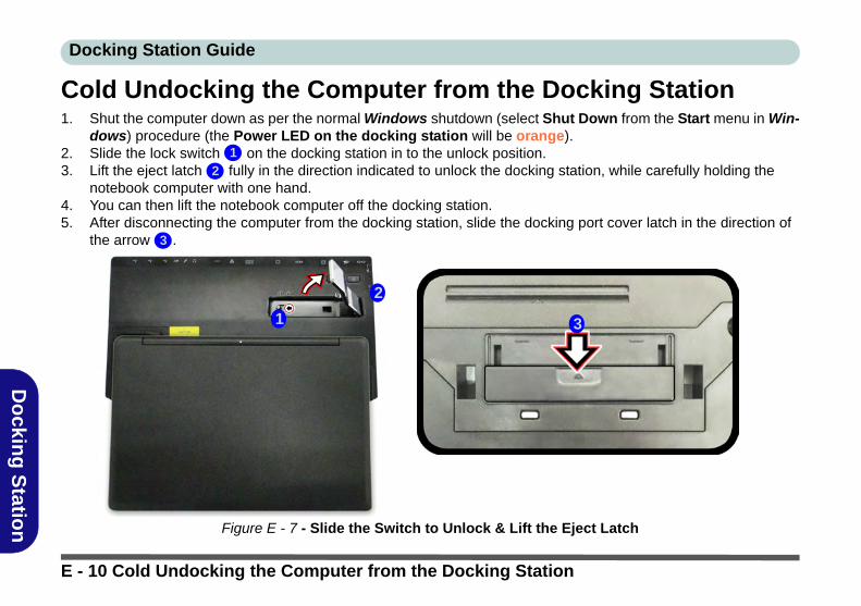
Docking Station Guide
Do
cking
Statio
n
Cold Undocking the Computer from the Docking Station1. Shut the computer down as per the normal Windows shutdown (select Shut Down from the Start menu in Win-
dows) procedure (the Power LED on the docking station will be orange).2. Slide the lock switch on the docking station in to the unlock position.3. Lift the eject latch fully in the direction indicated to unlock the docking station, while carefully holding the
notebook computer with one hand.4. You can then lift the notebook computer off the docking station.5. After disconnecting the computer from the docking station, slide the docking port cover latch in the direction of
the arrow .
Figure E - 7 - Slide the Switch to Unlock & Lift the Eject Latch
1
2
3
2
1 3
E - 10 Cold Undocking the Computer from the Docking Station

Docking Station Guide
Do
cking
Statio
n
Hot Docking the Computer to the Docking Station1. Remove all packing materials and place the docking station on a stable surface.2. Securely attach any peripherals you want to use with the docking station (e.g. keyboard and mouse) to their
ports.3. Attach the AC/DC adapter to the DC-In jack at the rear of the docking station, and then plug the AC power cord
into an outlet, and connect the AC power cord to the AC/DC adapter.4. The power button LED on the docking station will be orange.
Figure E - 8 - Docking Station with AC/DC Adapter Plugged
1
1
Hot Docking the Computer to the Docking Station E - 11

Docking Station Guide
Do
cking
Statio
n
5. Make sure the computer’s hot key driver is installed for hot docking/undocking the system.6. The computer should be on, however remove the AC/DC adapter from the notebook computer and then close
the computer’s lid/LCD and turn it over (if you are using the optional 9 cell battery you cannot hot dock the computer with the docking station).
7. Slide the notebook computer’s docking port cover latch in the direction of the arrow at point to open the cover (failure to open the cover of the docking port before connecting the computer to the docking station may result in irreparable damage to the connector on the docking station).
Figure E - 9 - Opening the Docking Port
2
Docking Port Cover
Make sure you keep the cover closed when the computer is not docked in the station. This willhelp prevent foreign objects and/or dust getting in to the contact area.
2
E - 12 Hot Docking the Computer to the Docking Station

Docking Station Guide
Do
cking
Statio
n
8. Ensure that the lock switch on the docking station is in the unlock position.9. Press the computer down onto the docking station so that the docking connectors line up (the Power LED on
the docking station will be orange).10. Slide the lock switch on the docking station in to the lock position .11. The Power LED on the docking station will be green and you can then use the docking station ports.
Figure E - 10 - Slide the Lock Switch
3
3
Moving the Docking Station
Note that if the notebook is docked withthe docking station, do not attempt tomove the docked unit in order to avoidlosing connection. If you wish to movethe docking station, then make sure youundock the notebook from the dockingstation before doing so.
AC/DC Adapter
Use only the docking station’s AC/DCadapter plugged-in to the docking sta-tion’s DC-In jack to power the computer.
Hot Docking the Computer to the Docking Station E - 13

Docking Station Guide
Do
cking
Statio
n
3
Hot Undocking the Computer from the Docking StationHot undocking using Windows:1. When the system is docked click the icon in the taskbar notification area and click Safely Remove Hard-
ware and Eject Media (Figure E - 11) from the menu.2. Select Eject Docking Station and the Undock Complete message will appear in the notification area of
the taskbar (the docking power LED will be Orange at this point and the ports, buttons and attached devices on the docking station will not work).
3. Follow steps 2 to 5 of the cold undocking procedure on page E - 10 to complete the undocking process.
Figure E - 11 - Using the Windows System to Hot Undock the Computer
12 3
1
2
Battery Condition
Note that if you attempt tohot undock the systemwhen the battery level islow (default below 10%)you will receive an errormessage. In this case shutthe system down to coldundock the notebook fromthe docking station, or letthe battery charge suffi-ciently until it is no longerclassed at a low level.
E - 14 Hot Undocking the Computer from the Docking Station

Docking Station Guide
Do
cking
Statio
n
Hot undocking using the Control Center:1. Make sure the computer’s hot key driver is installed for hot docking/undocking the system.2. Press the Fn + Esc key combination to run the Control Center. 3. Click the Docking Enable button in the Control Center (the icon displays the current docking status).4. The docking icon will change to the Docking Disable button to display the current status, and the Undock
Complete message will appear in the notification area of the taskbar (see over).
Figure E - 12 - Using the Control Center to Hot Undock the Computer
1
2
1
2
Battery Condition
Note that if you attempt tohot undock the systemwhen the battery level is low(default below 10%) you willreceive an error message.In this case shut the systemdown to cold undock thenotebook from the dockingstation, or let the batterycharge sufficiently until it isno longer classedat a low level.
Hot Undocking the Computer from the Docking Station E - 15

Docking Station Guide
Do
cking
Statio
n
5. Press the Fn + Esc key combination to run the Control Center.6. The docking power LED will be Orange at this point and the ports, buttons and attached devices on the docking
station will not work.7. If you do not wish to separate the notebook and docking station at this point you can click the icon in the Control
Center to re-dock the system.8. Follow steps 2 to 5 of the cold undocking procedure on page E - 10 to complete the undocking process.
E - 16 Hot Undocking the Computer from the Docking Station

Docking Station Guide
Do
cking
Statio
n
Power Button ConfigurationTo prevent your computer from entering a power-saving state if you choose to work with the lid/LCD closed,then it may be necessary to redefine what the computer is set to do if the lid/LCD is closed when plugged in.1. Go to the click Power Options (Hardware and Sound) control panel.2. Click Choose what closing the lid does (in the left pane).3. Set the When I close the lid: option when the computer is plugged in to Do nothing.4. Click Save Changes and close the control panel.
Figure E - 13 - Power Options (Choose what closing the lid does)
Hot Docking/Hot Undocking
& Power Saving ModesIf the computer is in a power-sav-ing state (Sleep or Hibernate), or isresuming from a power savingstate, do not attempt to hot dock orhot undock the system.
Power Button Configuration E - 17

Docking Station Guide
Do
cking
Statio
n
Docking Station Ports & JacksThe following will give a quick description of the interface (ports & jacks) which allow your docking station andcomputer to communicate with external devices, connect to the internet etc. When the notebook is docked to thedocking station all the ports on the docking station will function, however only some of the ports on the notebookwill function (see the note alongside each item for specific information.
Item Description Note
COM/RS232 Serial Port The COM/serial is a communication interface for data transfer,through which information transfers in or out one bit at a time. Thisport can be used to connect the computer to devices such asterminals and peripherals.
This port is supported in theWindows environment andat the DOS prompt,however there is no COMmouse support.
DC-In Jack Plug the supplied AC/DC adapter into this jack to power yourdocking statio and docked computer.
Use only the dockingstation’s AC/DC adapterplugged-in to the dockingstation’s DC-In jack topower the computer.
DVI-D Out Port The DVI-D Out (Digital Visual Interface-Digital) Port is a videoconnector interface supporting digital displays only. This allowsyou to connect an external monitor, TV or Flat Panel Display etc.as a display device by means of a DVI-D compatible cable.
E - 18 Docking Station Ports & Jacks

Docking Station Guide
Do
cking
Statio
n
External Monitor (VGA) Port
This port allows you to connect an external monitor, or Flat PanelDisplay, to get dual video or simultaneous display on the LCD andexternal monitor/FPD.
Use only the externalmonitor port on the dockingstation when the system isdocked.
HDMI-Out Port The HDMI-Out (High-Definition Multimedia Interface) is anaudio/video connector interface for transmitting uncompresseddigital streams. This allows you to connect an external monitor, TVor Flat Panel Display etc. as a display device by means of a HDMIcable. Note that HDMI carries both audio and video signals.
You can use the HDMI portson both the docking stationand the notebook,connected to two separatedisplays, when the systemis docked.
Item Description Note
Docking Station HDMI Port Resolutions Supported
Note that when the computer is docked to the docking station, and the docking station’s HDMI port is connected to an external display,the resolutions supported are as follows:
• DTV resolutions: 480i, 576i, 480p, 576p, 720p, 1080i to 1080p• PC resolutions: VGA, SVGA, XGA, SXGA to UXGA
Docking Station Ports & Jacks E - 19

Docking Station Guide
Do
cking
Statio
n
Headphone-Out Jack Headphones or speakers may be connected through this jack.Note: Set your system’s volume to a reduced level beforeconnecting to this jack.
You can use the headphoneand microphone jacks oneither the computer and/ordocking station when thesystem is docked.Microphone-In Jack Plug an external microphone in to this jack to record on your
computer.
RJ-45 LAN Jack This port supports LAN (Network) functions. Note: Broadband(e.g. ADSL) modems usually connect to the LAN port.
Note that when the systemis docked the notebook’sLAN Jack can no longer beused and you must use thedocking station’s LAN jackas the network jack only.
Item Description Note
Wake On LAN Support
Note that when the system is docked Wake On LAN will be disabled. Wake On LAN is only supported in AC Mode(i.e.when the computer is powered by its AC/DC adapter and not by the battery). When the system is docked, the powerfor a docked unit should be provided only by the docking station’s AC/DC adapter plugged in to the DC-In jack at the rearof the docking station (and not the computer’s AC/DC adapter), and therefore Wake On LAN is not supported by a dockedsystem.
E - 20 Docking Station Ports & Jacks

Docking Station Guide
Do
cking
Statio
n
Security Lock Slot To prevent possible theft, a Kensington-type lock can be attachedto this slot. Locks can be purchased at any computer store.
S/PDIF-Out Jack This S/PDIF (Sony/Philips Digital Interface Format) Out Portallows you to connect your DVD-capable PC to a Dolby AC-3compatible receiver for “5.1” or ‘dts’ surround sound.
Item Description Note
Docking Station - S/PDIF Out Jack
Note that the docking station’s S/PDIF Out Jack does not support optical fibre cables, and when the computer is docked to the dockingstation you must use the docking station’s S/PDIF Out Jack for any S/PDIF connections.
Docking Station Ports & Jacks E - 21

Docking Station Guide
Do
cking
Statio
n
USB 2.0/1.1 Ports*
USB 3.0 Ports
These USB 2.0 compatible ports (USB 2.0 is fully USB 1.1compliant) are for low-speed peripherals such as keyboards, miceor scanners, and for high-speed peripherals such as externalHDDs, digital video cameras or high-speed scanners etc. Devicescan be plugged into the computer, and unplugged from thecomputer, without the need to turn the system off (if the powerrating of your USB device is 500mA or above, make sure you usethe power supply which comes with the device).
The USB 3.0 ports are denoted by their blue color; USB 2.0ports are colored black. USB 3.0 will transfer data much fasterthan USB 2.0, and is backwards-compatible with USB 2.0.
Note: The powered USB 3.0 port function is designed to helpcharge USB compliant devices, but is not designed to allowtheir operation.
You can use the ports onboth the computer and thedocking station when thesystem is docked.
*Note: The powered USB3.0 port (see Figure E -3 on page E - 6) will supplypower when the dockingstation is powered by theAC/DC adapter plugged intoa working outlet, (this maynot work with certain devic-es). The notebook does notneed to be docked for this tofunction. There is no LED toindicate a charge status onthe docking station.
Item Description Note
3.03
E - 22 Docking Station Ports & Jacks
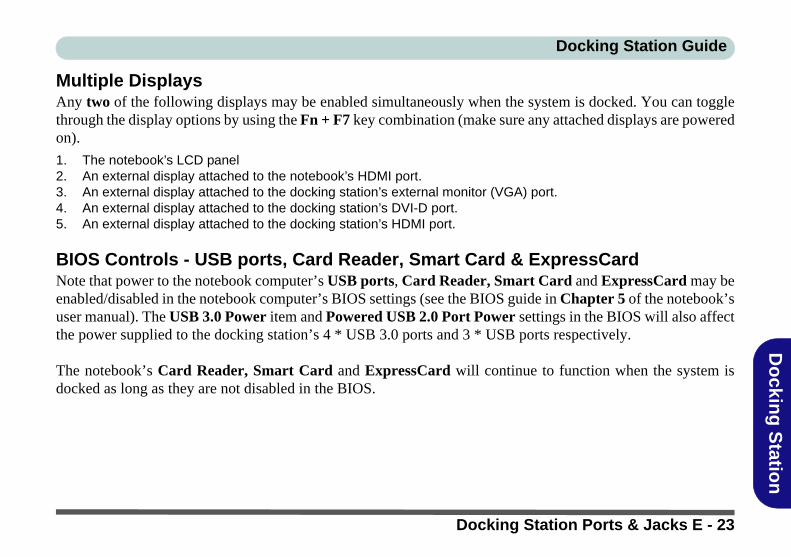
Docking Station Guide
Do
cking
Statio
n
Multiple DisplaysAny two of the following displays may be enabled simultaneously when the system is docked. You can togglethrough the display options by using the Fn + F7 key combination (make sure any attached displays are poweredon).
1. The notebook’s LCD panel2. An external display attached to the notebook’s HDMI port.3. An external display attached to the docking station’s external monitor (VGA) port.4. An external display attached to the docking station’s DVI-D port.5. An external display attached to the docking station’s HDMI port.
BIOS Controls - USB ports, Card Reader, Smart Card & ExpressCardNote that power to the notebook computer’s USB ports, Card Reader, Smart Card and ExpressCard may beenabled/disabled in the notebook computer’s BIOS settings (see the BIOS guide in Chapter 5 of the notebook’suser manual). The USB 3.0 Power item and Powered USB 2.0 Port Power settings in the BIOS will also affectthe power supplied to the docking station’s 4 * USB 3.0 ports and 3 * USB ports respectively.
The notebook’s Card Reader, Smart Card and ExpressCard will continue to function when the system isdocked as long as they are not disabled in the BIOS.
Docking Station Ports & Jacks E - 23

Docking Station Guide
Do
cking
Statio
n
One Button Hard Disk BackupWhen the system is docked you can press the Hard Disk Backup Button ( Figure E - 14) to launch the Win-dows Recovery (see overleaf) application. If you do not have a hard disk installed in the docking station you canset the Windows File History application to backup to any attached hard disk, CD/DVD or non system partitionof your computer.
Figure E - 14 - Front View (HDD Backup Button)
1
1
Docking Station -
HDD Support
The docking station’sSATA port only supportsHDDs with a SATAII (orlower) interface.
E - 24 One Button Hard Disk Backup

Docking Station Guide
Do
cking
Statio
n
Backup ProcedureYou can choose to backup individual files and folders or alternatively create a System Image Backup.
1. Press the hard disk backup button.2. Windows Recovery control Panel.3. Click File History.4. If you are on the first run of the program click Turn On.
Figure E - 15 - Windows File History (Turn On)
Backup Procedure E - 25

Docking Station Guide
Do
cking
Statio
n
5. You can click Select drive to (you can also choose to backup to a network location).6. Click OK.
Figure E - 16 - Select Drive
E - 26 Backup Procedure

Docking Station Guide
Do
cking
Statio
n
System Image BackupFollow the instructions on these pages to perform a a full system image backup (if you want to backup individualfiles and folders see Figure on page E - 31).
1. Click System Image Backup from the File History control panel.2. Click Create a system image from the Backup and Restore window.3. Click to select where you would like to save the backup (e.g the drive installed on the docking station) and click
Next.
Figure E - 17 - System Image Backup
Backup Procedure E - 27

Docking Station Guide
Do
cking
Statio
n
4. Select the drives you want to include in the backup and click Next.5. Click Start backup.6. Windows will then save the backup (this may take some time).
Figure E - 18 - Select Drives and Confirm
E - 28 Backup Procedure

Docking Station Guide
Do
cking
Statio
n
System Image RecoveryYou can recover your backed up system image by using Update and Security application in Settings.
1. Click the Settings item in the Start Menu.2. Click Update & security and click Recovery.3. Click Restart Now under Advanced startup and the computer will restart to begin the recovery process.
Figure E - 19 - Settings - Update and Security (Recovery)
4. Click Troubleshoot.and then click Advanced Options.
Backup Procedure E - 29

Docking Station Guide
Do
cking
Statio
n
5. Click System Image Recovery.
Figure E - 20 - Troubleshoot / advanced Options
6. The system will the prepare to recover the system image.7. You will be asked to select your account by clicking on the account name.8. Input the system password when prompted and click Continue.9. The system will then re-image the computer.10. You should then either choose to Use the latest available system image (recommended) if required, or
browse to the image stored on the docking station by clicking in Select a system image and clicking Next to go to the image of the backup required.
11. Click to select the location of the backup and click Next.12. Click to select the available backup and click Next.13. You can then choose any additional restore options required, and then click Next.14. Click Finish > Yes to start restoring the data (this may take some time).15. Click Restart Now to complete the procedure.
E - 30 Backup Procedure

Docking Station Guide
Do
cking
Statio
n
File History Backup1. You can click Select drive to select a drive to backup the libraries, desktop, contacts and favorites (see
below) to by clicking select drive (you can also choose to backup to a network location).
Figure E - 21 - Select Drive (Backup Location)
Windows File History Backup
Windows File History does not allow thecreation of full system images, and does notallow you to back up everything on the harddisk drive.
Windows File History allows you to backupfiles in libraries, desktop files, contactsand favorites. You can add folders to librar-ies to include in a backup, and you can ex-clude certain library files from being backedup, but you cannot include files from out-side the libraries or desktop.
This is designed to work more efficiently, andto be less cumbersome, in protecting a us-er’s essential personal files and not the sys-tem files, OS and applications which caneasily be reinstalled.
Backup Procedure E - 31

Docking Station Guide
Do
cking
Statio
n
2. Click Exclude folders and then click Add to select any folders you do not want to back up as part of the process, then click Save changes to confirm.
Figure E - 22 - Exclude Folders
E - 32 Backup Procedure

Docking Station Guide
Do
cking
Statio
n
3. Click Advanced settings, make any changes required and click Save Changes:
• Save copies of files: Set the interval of the backup (in Windows 10 the default is a continuous backup that takes a snapshot of the files every hour).
• Keep saved versions: Set how long saved versions are to be kept for.• Create or join a homegroup: You can advertise your backup drive as a backup drive for your homegroup to
allow all Windows computers in your homegroup to back up files to this centralized backup location.
Figure E - 23 - Advanced Settings
Backup Procedure E - 33

Docking Station Guide
Do
cking
Statio
n
4. Click Run now to begin the backup process (you can click Stop at any time if you need to cancel the backup process).
Figure E - 24 - Run Now
E - 34 Backup Procedure

Docking Station Guide
Do
cking
Statio
n
Restoring Files from File History Backup1. Press the hard disk backup button.2. Windows File History application will be launched.3. Click “Restore personal files”.
Figure E - 25 - Restore Personal Files
Backup Procedure E - 35

Docking Station Guide
Do
cking
Statio
n
4. The most recent backup will appear in the Home - File History window (you can click the arrows to scroll through the different backup date files if they are retained).
5. Click the button to restore the whole backup to the original location (you can select individual files or shift-click or Ctrl-click to select multiple files and then click the button ).
Figure E - 26 - Home File History
E - 36 Backup Procedure

Docking Station Guide
Do
cking
Statio
n
6. If the files are being restored to their original location then you will be asked if you want to replace files, skip files or decide for each file.
7. You can decide which file to keep, or select both to add a file with a number added as a suffix.
Figure E - 27 - Replace or Skip Files/File Conflicts
Backup Procedure E - 37

Docking Station Guide
Do
cking
Statio
n
SpecificationsStorage
One Changeable 12.7mm(H) Super Multi ODD / Blu-ray Combo ODD or 2.5" / 9.5 mm(H) HDD Caddy with SATA (Serial) Interface (Factory Option)
Interface and Ports
Three USB 2.0 PortsFour USB 3.0 Ports (including 1 * powered USB port)One External Monitor PortOne DVI-D Out PortOne HDMI™ Out Port (with HDCP)One Headphone-Out JackOne Microphone-In JackOne S/PDIF-Out JackOne RJ-45 LAN JackOne RS232 (Serial) COM PortOne Docking Port (Hot Plug)One DC-In Jack
Buttons & Switches
Power Button, Notebook Eject Latch, Docking Lock Switch &HDD Backup Button
Power
Full Range AC/DC 65W AdapterAC input 100 - 240V, 50 - 60Hz, DC Output 19V, 3.4A
Security
Security (Kensington® Type) Lock Slot
LED Indicators
Adapter Power/SystemSystem Operation Indicator
Environmental Spec
Temperature Operating: 5°C - 35°CNon-Operating: -20°C - 60°CRelative HumidityOperating: 20% - 80%Non-Operating: 10% - 90%
Dimensions & Weight
380mm (w) * 206mm (d) * 33mm (h)0.85kg
E - 38 Specifications