Embed Size (px)
Citation preview
CONTENTS 1
V600 OWNER’S MANUAL Table of Contents
V600 MENU TREE .................................................................................................5
V600 BASIC REFUSE SYSTEM SETUP .....................................................................6
1.0 VULCAN SINGLE LINE (VSL) TECHNOLOGY, V600 ELECTRONICS SYSTEM........7 1.1 Load Cells And Air Sensors...............................................................................10
1.2 VSL Vulcoders...................................................................................................11
1.3 V600 Meter ........................................................................................................11
1.4 Explanation of Meter Channels..........................................................................12
1.5 Electronics Installation .......................................................................................13
2.0 V600 METER OPERATION ............................................................................17 2.1 Power / Menu Button Operation ........................................................................17
2.1.1 Powering The Meter On / Off ..................................................................17
2.1.2 Entering And Exiting The Meter Program Menu .....................................17
2.2 Arrow Buttons Operation ...................................................................................18
2.2.1 Changing Display Intensity .....................................................................18
2.2.2 Increase / Decrease Meter Program Settings .........................................18
2.3 Cycle Button Operation......................................................................................19
2.3.1 Locking The Meter On A Particular Channel...........................................19
2.3.2 Scroll Through The Meter Program Menu Functions ..............................19
2.4 Enter Button Operation ......................................................................................20
2.4.1 Selects / Enters Program Menu Items ....................................................20
2.4.2 Stores Newly Adjusted Meter Settings....................................................20
2.4.3 Displays Time and Date..........................................................................20
2.4.4 Prints A Weight Ticket ............................................................................20
2.5 Tare / Zero Button Operation.............................................................................21
2.5.1 Zeroes Meter Values ..............................................................................21
2.5.2 Zeroes Meter Display In The Pick-up / Delivery Mode............................21
2.5.3 Displays Gross Weight In The Net And Pick-up / Delivery Modes ..........21
June 21, 2006 VULCAN ON-BOARD SCALES 1-800-237-0022 Doc. 44-10032-001 Rev. C © STRESS-TEK, INC. 2006
2 CONTENTS
2.6 Vulcoder Updating .............................................................................................22
3.0 V600 - PROGRAM MENU (SYSTEM SETUP) ................................................... 23 3.1 Entering The Program Menu .............................................................................23
3.2 Entering The Configure System Menu...............................................................24
3.2.1 Configure The Weight Mode (Gross, Net, Or Pick-Up) ...........................25
3.2.2 Configure The Display Code...................................................................26
3.2.3 Configure The Set Points........................................................................28
3.2.3A Configure Relay 1 .....................................................................29
3.2.3B Configure Relay 2 .....................................................................31
3.2.3C Configure Delta Weight .............................................................32
3.2.3D Configure On Time....................................................................33
3.2.4 Configure The Channel Cycle Time........................................................35
3.2.5 Configure The RS232 Port .....................................................................36
3.2.6 Configure The Print Headers ..................................................................37
3.2.7 Configure The Date ................................................................................39
3.2.8 Configure The Time ................................................................................41
3.2.9 Configure The Scale ID ..........................................................................42
3.2.10 Configure The Lock (Tare and Cal Lockout)...........................................43
3.2.11 Exiting The Configure System Menu ......................................................44
3.3 Entering The Setup / Calibrate Menu ................................................................44
3.3.1 Setting The Tare Weight.........................................................................44
3.3.2 Setting The Cal Number .........................................................................46
3.3.3 Setting The Cal Weight...........................................................................47
3.3.4 Setting The Post Calibration ...................................................................49
3.3.5 Setting The Grad Size ............................................................................51
3.3.6 Setting The Units (Lb or Kg) ...................................................................51
3.3.7 Setting The Auto Zero Tracking Range ..................................................52
3.3.8 Setting The Sample Size .......................................................................53
3.3.9 Exiting The Configure System Menu ......................................................55
3.4 Sequencing Channels .......................................................................................55
3.4.1 Manual Sequencing ................................................................................56
3.5 System Test Menu.............................................................................................57
June 21, 2006 VULCAN ON-BOARD SCALES 1-800-237-0022 Doc. 44-10032-001 Rev. C © STRESS-TEK, INC. 2006
CONTENTS 3
3.5.1 Test Keypad............................................................................................58
3.5.2 Test LED’s ..............................................................................................58
3.5.3 Test Memory...........................................................................................59
3.5.4 Test VSL Comm .....................................................................................60
3.5.5 Test L / C Offset......................................................................................61
3.6 Exiting The Program Menu ................................................................................62
4.0 V600 CALIBRATION.....................................................................................63 4.1 Weight Measuring Methods ...............................................................................63
4.1.1 Gross Vehicle Weight .............................................................................64
4.1.2 Net Payload Weight ................................................................................64
4.2 Procedure For Entering Tare Weights ...............................................................64
4.2.1 Entering Tare Weight For A Typical 2 - Channel, Truck & Trailer
System....................................................................................................64
4.2.2 Entering Tare Weight For A Typical Short Logger System .....................66
4.2.3 Entering Tare Weight For A Typical Refuse System...............................68
4.3 Procedure For Entering Starting Calibration Numbers.......................................69
4.4 Fine Tuning The Calibration Number For Gross Vehicle Weight Method
When Only One Channel Per Truck Or Trailer Is Used .....................................71
4.5 Fine Tuning The Calibration Number For Gross Vehicle Weight And Net
Payload Weight Methods When More Than One Channel Is Used Per Truck
Or Trailer............................................................................................................74
5.0 MAINTENANCE.............................................................................................79 5.1 Driver's Daily Vehicle Inspection........................................................................79
5.2 Preventative Maintenance And Vulcan Torque Specifications...........................80
6.0 TROUBLESHOOTING.....................................................................................87 6.1 Vulcan Check-out Box .......................................................................................88
6.2 Load Cell Evaluation Tests ................................................................................89
6.2.1 Leakage Test Procedure ........................................................................89
6.2.2 Tare Test Procedure...............................................................................90
6.2.3 Resistance Test Procedure.....................................................................93
June 21, 2006 VULCAN ON-BOARD SCALES 1-800-237-0022 Doc. 44-10032-001 Rev. C © STRESS-TEK, INC. 2006
4 CONTENTS
6.3 V600 Meter Error Codes....................................................................................94
6.3.1 Err 01......................................................................................................94
6.3.2 Err 02......................................................................................................94
6.3.3 Err 03......................................................................................................95
6.3.4 Err 04......................................................................................................95
6.3.5 Err 05......................................................................................................96
6.3.6 Err 06......................................................................................................96
6.3.7 Err 07......................................................................................................97
6.3.8 Err 08......................................................................................................97
6.3.9 Err 09......................................................................................................98
6.3.10 Err 10......................................................................................................98
6.3.11 Err 11......................................................................................................98
6.4 System Malfunctions .........................................................................................99
6.4.1 No Indicator Display Or Function Lights .................................................99
6.4.2 Unable To Enter Tare Or Calibration Numbers.....................................100
6.4.3 Meter Reading Drifts Or Wanders With Time .......................................100
6.4.4 Meter Reading Does Not Change When Truck Is Being Loaded..........102
6.4.5 Meter Stops Powering Up After Displaying All Digits ............................102
6.4.6 Meter Displays LO-LO ..........................................................................103
6.5 Troubleshooting Worksheet.............................................................................106
6.6 Troubleshooting Assistance And Replacement Parts......................................108
7.0 APPENDIX ................................................................................................. 109 7.1 Starting Calibration Numbers...........................................................................110
7.2 System Specifications .....................................................................................111
7.3 Assistance In Fine Tuning Your Scale System (Primarily For Two Channels
On One Truck Application Only) ......................................................................112
7.4 Keeping Records .............................................................................................114
June 21, 2006 VULCAN ON-BOARD SCALES 1-800-237-0022 Doc. 44-10032-001 Rev. C © STRESS-TEK, INC. 2006
V600 MENU TREE 5
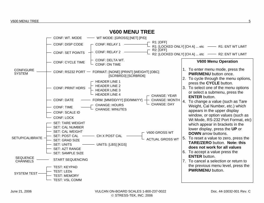
V600 MENU TREE CONF: WT. MODE
CONF: DISP CODE
CONF: SET POINTS
CONF: CYCLE TIME
CONF: RS232 PORT
CONF: PRINT HDRS
CONF: DATE
CONF: TIMECONF: SCALE IDCONF: LOCKSET: TARE WEIGHTSET: CAL NUMBERSET: CAL WEIGHTSET: POST CALSET: GRAD SIZESET: UNITSSET: AZT RANGESET: SAMPLE SIZE
START SEQUENCING
TEST: KEYPADTEST: LEDsTEST: MEMORYTEST: VSL COMM
WT MODE: [GROSS] [NET] [P/D]
CONF: RELAY 1
CONF: RELAY 2
CONF: DELTA WT.CONF: ON TIME
FORMAT: [NONE] [PRINT] [WEIGHT] [OBC]
HEADER LINE 1HEADER LINE 2HEADER LINE 3HEADER LINE 4
FORM: [MM/DD/YY] [DD/MM/YY]CHANGE: HOURSCHANGE: MINUTES
CH X POST CAL
UNITS: [LBS] [KGS]
R1: [OFF]R1: [LOCKED ONLY] [CH A] ... etc
R2: [LOCKED ONLY] [CH A] ... etcR2: [OFF]
R1: ENT WT LIMIT
R2: ENT WT LIMIT
CHANGE: YEARCHANGE: MONTHCHANGE: DAY
V600 GROSS WT
ACTUAL GROSS WT
CONFIGURESYSTEM
SEQUENCECHANNELS
SYSTEM TEST
TE
[SCRBRD3] [SCRBRD6]
SETUP/CALIBRA
V600 Menu Operation 1. To enter menu mode, press the
PWR/MENU button once. 2. To cycle through the menu options,
press the CYCLE button. 3. To select one of the menu options
or select a submenu, press the ENTER button.
4. To change a value (such as Tare Weight, Cal Number, etc.) which appears in the upper display window, or option values (such as Wt Mode, RS-232 Port Format, etc) which appear in brackets in the lower display, press the UP or DOWN arrow buttons.
5. To reset a value to zero, press the TARE/ZERO button. Note: this does not work for all values
6. To accept a value press the ENTER button.
7. To cancel a selection or return to the previous menu level, press the PWR/MENU button.
June 21, 2006 VULCAN ON-BOARD SCALES 1-800-237-0022 Doc. 44-10032-001 Rev. C © STRESS-TEK, INC. 2006
6 V600 BASIC REFUSE SYSTEM SETUP
V600 BASIC REFUSE SYSTEM SETUP 1. Enter the Program Menu by pressing the PWR/MENU button after the meter has finished its start up routine, Section 3.1. 2. Configure System will be displayed on the smaller display. Press the ENTER button to enter the Configure System Menu, Section 3.2. 3. Configure the Weight Mode: Press the ENTER button to select the CONF: WT. MODE Menu. Most users will set the weight mode to the
Pickup/Deliver Mode by pressing the UP or DOWN ARROW buttons until [P/D] is displayed. Press the ENTER button to save the desired selection. See Section 3.2.1 for more details.
4. Set the vehicle Tare Weight: Press the PWR/MENU button to return to the Configure System Menu. Press the CYCLE button to advance to the
Setup/Calibrate Menu. Press the ENTER button to enter the Setup/Calibrate Menu. Press the ENTER button to select the SET: TARE WEIGHT Menu. Press either the UP or DOWN ARROW buttons to adjust the number to the desired Tare Weight. Most users will set the Tare Weight to zero to monitor net payload. Press the ENTER button to save the desired Tare Weight. See Section 3.3.1 for more details.
5. Set the Grad Size: Press the CYCLE button to advance to the SET: GRAD SIZE Menu is displayed. Press the ENTER button to enter the SET:
GRAD SIZE Menu. Press either the UP or DOWN ARROW buttons to adjust the desired Grad Size. Most users find that leaving the Grad Size set to 50 works well without being too sensitive. Press the ENTER button to save the desired Grad Size. See section 3.3.5 for more details.
6. Set the Auto Zero Tracking Range to Zero: Press the CYCLE button to advance to the SET: AZT RANGE Menu. Press the ENTER button to
enter the SET: AZT RANGE Menu. Press either the UP or DOWN ARROW buttons to adjust the AZT Range to zero. Press the ENTER button to save the desired AZT Range. See section 3.3.7 for more details.
7. Exit the Program Menu: Press the PWR/MENU button until the display returns to the normal operating mode. See section 3.6 for more details.
June 21, 2006 VULCAN ON-BOARD SCALES 1-800-237-0022 Doc. 44-10032-001 Rev. C © STRESS-TEK, INC. 2006
CHAPTER 1 7
C H A P T E R 1 . 0
VULCAN SINGLE LINE (VSL) TECHNOLOGY
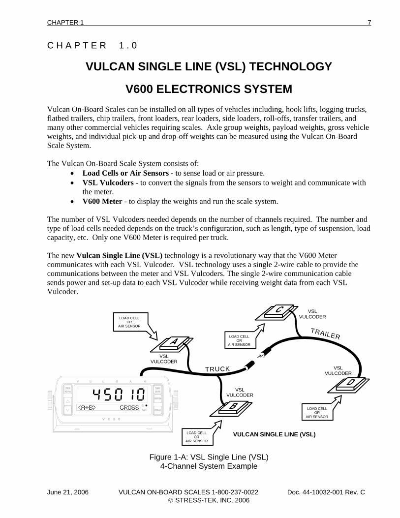
V600 ELECTRONICS SYSTEM Vulcan On-Board Scales can be installed on all types of vehicles including, hook lifts, logging trucks, flatbed trailers, chip trailers, front loaders, rear loaders, side loaders, roll-offs, transfer trailers, and many other commercial vehicles requiring scales. Axle group weights, payload weights, gross vehicle weights, and individual pick-up and drop-off weights can be measured using the Vulcan On-Board Scale System. The Vulcan On-Board Scale System consists of:
• Load Cells or Air Sensors - to sense load or air pressure. • VSL Vulcoders - to convert the signals from the sensors to weight and communicate with
the meter. • V600 Meter - to display the weights and run the scale system.
The number of VSL Vulcoders needed depends on the number of channels required. The number and type of load cells needed depends on the truck’s configuration, such as length, type of suspension, load capacity, etc. Only one V600 Meter is required per truck. The new Vulcan Single Line (VSL) technology is a revolutionary way that the V600 Meter communicates with each VSL Vulcoder. VSL technology uses a single 2-wire cable to provide the communications between the meter and VSL Vulcoders. The single 2-wire communication cable sends power and set-up data to each VSL Vulcoder while receiving weight data from each VSL Vulcoder.
TRUCK
TRAILER
VSLVULCODER
VSLVULCODER
VULCODER
VSLVULCODER
VSL
VULCAN SINGLE LINE (VSL)
LOAD CELLOR
AIR SENSOR
LOAD CELLOR
AIR SENSOR
LOAD CELLOR
AIR SENSOR
LOAD CELLOR
AIR SENSOR
Figure 1-A: VSL Single Line (VSL) 4-Channel System Example
June 21, 2006 VULCAN ON-BOARD SCALES 1-800-237-0022 Doc. 44-10032-001 Rev. C © STRESS-TEK, INC. 2006
8 CHAPTER 1
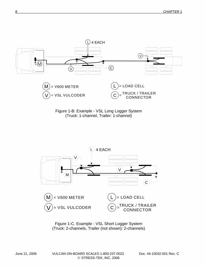
4 EACH
C
C TRUCK / TRAILERCONNECTOR
= LOAD CELL
== VSL VULCODER
= V600 METER
V
V
V
Figure 1-B: Example - VSL Long Logger System (Truck: 1-channel, Trailer: 1-channel)
L
M
C TRUCK / TRAILERCONNECTOR
= LOAD CELL
= = VSL VULCODER
= V600 METER
4 EACH
C
V
V
V
Figure 1-C. Example - VSL Short Logger System (Truck: 2-channels, Trailer (not shown): 2-channels)
June 21, 2006 VULCAN ON-BOARD SCALES 1-800-237-0022 Doc. 44-10032-001 Rev. C © STRESS-TEK, INC. 2006
CHAPTER 1 9
M
V V
L
= LOAD CELL
= VSL VULCODER
= V600 METER
6 EACH
V
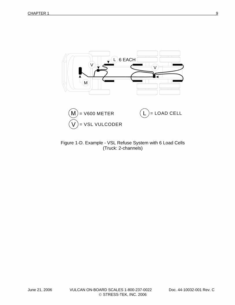
Figure 1-D. Example - VSL Refuse System with 6 Load Cells (Truck: 2-channels)
June 21, 2006 VULCAN ON-BOARD SCALES 1-800-237-0022 Doc. 44-10032-001 Rev. C © STRESS-TEK, INC. 2006
10 CHAPTER 1
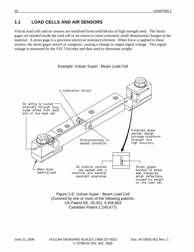
1.1 LOAD CELLS AND AIR SENSORS Vulcan load cells and air sensors are machined from solid blocks of high strength steel. The Strain gages are bonded inside the load cell or air sensor to sense extremely small dimensional changes in the material. A strain gage is a precision electrical resistance element. When force is applied to these sensors, the strain gages stretch or compress, causing a change in output signal voltage. This signal voltage is measured by the VSL Vulcoder and then used to determine weight.
Example: Vulcan Super - Beam Load Cell
Figure 1-E: Vulcan Super - Beam Load Cell (Covered by one or more of the following patents:
US Patent RE. 35,301, 4,459,863 Canadian Patent 1,245,677)
June 21, 2006 VULCAN ON-BOARD SCALES 1-800-237-0022 Doc. 44-10032-001 Rev. C © STRESS-TEK, INC. 2006
CHAPTER 1 11
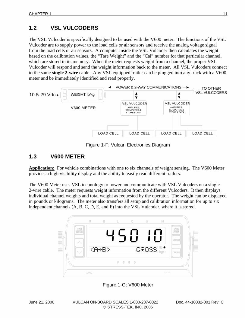
1.2 VSL VULCODERS The VSL Vulcoder is specifically designed to be used with the V600 meter. The functions of the VSL Vulcoder are to supply power to the load cells or air sensors and receive the analog voltage signal from the load cells or air sensors. A computer inside the VSL Vulcoder then calculates the weight based on the calibration values, the “Tare Weight” and the “Cal” number for that particular channel, which are stored in its memory. When the meter requests weight from a channel, the proper VSL Vulcoder will respond and send the weight information back to the meter. All VSL Vulcoders connect to the same single 2-wire cable. Any VSL equipped trailer can be plugged into any truck with a V600 meter and be immediately identified and read properly.
WEIGHT lb/kg10.5-29 Vdc
V600 METER
LOAD CELL
POWER & 2-WAY COMMUNICATIONS TO OTHERVSL VULCODERS
VSL VULCODERAMPLIFIES,
COMPUTES &STORES DATA
VSL VULCODERAMPLIFIES,
COMPUTES &STORES DATA
LOAD CELL LOAD CELL LOAD CELL
Figure 1-F: Vulcan Electronics Diagram 1.3 V600 METER Application: For vehicle combinations with one to six channels of weight sensing. The V600 Meter provides a high visibility display and the ability to easily read different trailers. The V600 Meter uses VSL technology to power and communicate with VSL Vulcoders on a single 2-wire cable. The meter requests weight information from the different Vulcoders. It then displays individual channel weights and total weight as requested by the operator. The weight can be displayed in pounds or kilograms. The meter also transfers all setup and calibration information for up to six independent channels (A, B, C, D, E, and F) into the VSL Vulcoder, where it is stored.
Figure 1-G: V600 Meter
June 21, 2006 VULCAN ON-BOARD SCALES 1-800-237-0022 Doc. 44-10032-001 Rev. C © STRESS-TEK, INC. 2006
12 CHAPTER 1
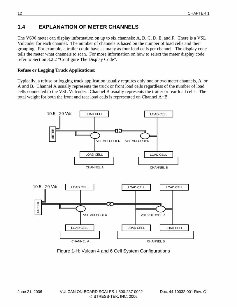
1.4 EXPLANATION OF METER CHANNELS The V600 meter can display information on up to six channels: A, B, C, D, E, and F. There is a VSL Vulcoder for each channel. The number of channels is based on the number of load cells and their grouping. For example, a trailer could have as many as four load cells per channel. The display code tells the meter what channels to scan. For more information on how to select the meter display code, refer to Section 3.2.2 “Configure The Display Code”. Refuse or Logging Truck Applications: Typically, a refuse or logging truck application usually requires only one or two meter channels, A, or A and B. Channel A usually represents the truck or front load cells regardless of the number of load cells connected to the VSL Vulcoder. Channel B usually represents the trailer or rear load cells. The total weight for both the front and rear load cells is represented on Channel A+B.
ME
TER
VSL VULCODER VSL VULCODER
LOAD CELL LOAD CELL LOAD CELL
LOAD CELLLOAD CELLLOAD CELL
CHANNEL A
10.5 - 29 Vdc
10.5 - 29 Vdc
VSL VULCODER VSL VULCODER
LOAD CELL LOAD CELL
ME
TER
CHANNEL A
LOAD CELL LOAD CELL
CHANNEL B
CHANNEL B
Figure 1-H: Vulcan 4 and 6 Cell System Configurations
June 21, 2006 VULCAN ON-BOARD SCALES 1-800-237-0022 Doc. 44-10032-001 Rev. C © STRESS-TEK, INC. 2006
CHAPTER 1 13
1.5 ELECTRONICS INSTALLATION 1. Tape the VSL Vulcoder connectors prior to routing the cabling to avoid contamination. Mount
the VSL Vulcoders on the inside of the truck frame rail or next to a structural member. The VSL Vulcoder mounting surface must be in an area protected from road and hauling debris.
2. Route the black cable to the load cells. (Do not trim the black cable to length). 3. Important: Check the connectors to make sure they are clean and dry. Do not get moisture,
contact cleaner, or any other substance inside of the connectors. 4. Check the load cell connector coming from the VSL Vulcoder for an O-ring. Attach the black
cable connectors to the bulkhead connectors on the load cells. Make sure they are finger tight plus an additional 1/8 of a turn more with channel lock pliers. The additional tightening is necessary to compress the O-ring. This prevents scale errors which can occur from moisture entering into the load cell connector. Caution: Do not over tighten the connectors as this can damage them.
5. Route the single 2-wire orange VSL Vulcoder cable from the meter in the cab to the last VSL
Vulcoder in the system. Be sure to route the cable to the meter and do not trim any excess wire off at the meter. Trim off the excess cable to approximately 1' - 2' of extra orange cable at the location of the VSL Vulcoder splice to allow for the splice. Note: On a truck-to-trailer connection, these wires may be routed using the existing truck-to-trailer wire harness if two unused ungrounded wires are available. Additionally, you may follow the existing wire harness and use a separate connector of your choice between the truck and trailer. If using the separate connector, for the best and most reliable connection, connect each color wire to two pin connections. For example, connect the green wire to the top two pins of a 4-pin truck-to-trailer connector, and the white wires to the bottom two pins.
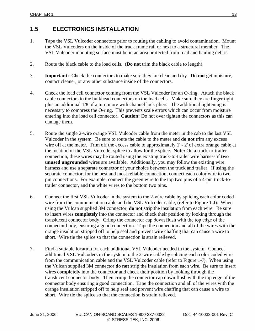
6. Connect the first VSL Vulcoder in the system to the 2-wire cable by splicing each color coded
wire from the communication cable and the VSL Vulcoder cable, (refer to Figure 1-J). When using the Vulcan supplied 3M connector, do not strip the insulation from each wire. Be sure to insert wires completely into the connector and check their position by looking through the translucent connector body. Crimp the connector cap down flush with the top edge of the connector body, ensuring a good connection. Tape the connection and all of the wires with the orange insulation stripped off to help seal and prevent wire chaffing that can cause a wire to short. Wire tie the splice so that the connection is strain relieved.
7. Find a suitable location for each additional VSL Vulcoder needed in the system. Connect
additional VSL Vulcoders in the system to the 2-wire cable by splicing each color coded wire from the communication cable and the VSL Vulcoder cable (refer to Figure 1-J). When using the Vulcan supplied 3M connector do not strip the insulation from each wire. Be sure to insert wires completely into the connector and check their position by looking through the translucent connector body. Then crimp the connector cap down flush with the top edge of the connector body ensuring a good connection. Tape the connection and all of the wires with the orange insulation stripped off to help seal and prevent wire chaffing that can cause a wire to short. Wire tie the splice so that the connection is strain relieved.
June 21, 2006 VULCAN ON-BOARD SCALES 1-800-237-0022 Doc. 44-10032-001 Rev. C © STRESS-TEK, INC. 2006
14 CHAPTER 1
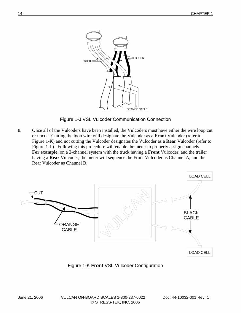
Figure 1-J VSL Vulcoder Communication Connection 8. Once all of the Vulcoders have been installed, the Vulcoders must have either the wire loop cut
or uncut. Cutting the loop wire will designate the Vulcoder as a Front Vulcoder (refer to Figure 1-K) and not cutting the Vulcoder designates the Vulcoder as a Rear Vulcoder (refer to Figure 1-L). Following this procedure will enable the meter to properly assign channels.
For example, on a 2-channel system with the truck having a Front Vulcoder, and the trailer having a Rear Vulcoder, the meter will sequence the Front Vulcoder as Channel A, and the Rear Vulcoder as Channel B.
CUT
ORANGECABLE
BLACKCABLE
LOAD CELL
LOAD CELL
Figure 1-K Front VSL Vulcoder Configuration
June 21, 2006 VULCAN ON-BOARD SCALES 1-800-237-0022 Doc. 44-10032-001 Rev. C © STRESS-TEK, INC. 2006
CHAPTER 1 15
ORANGECABLE
BLACKCABLE
LOAD CELL
LOAD CELL
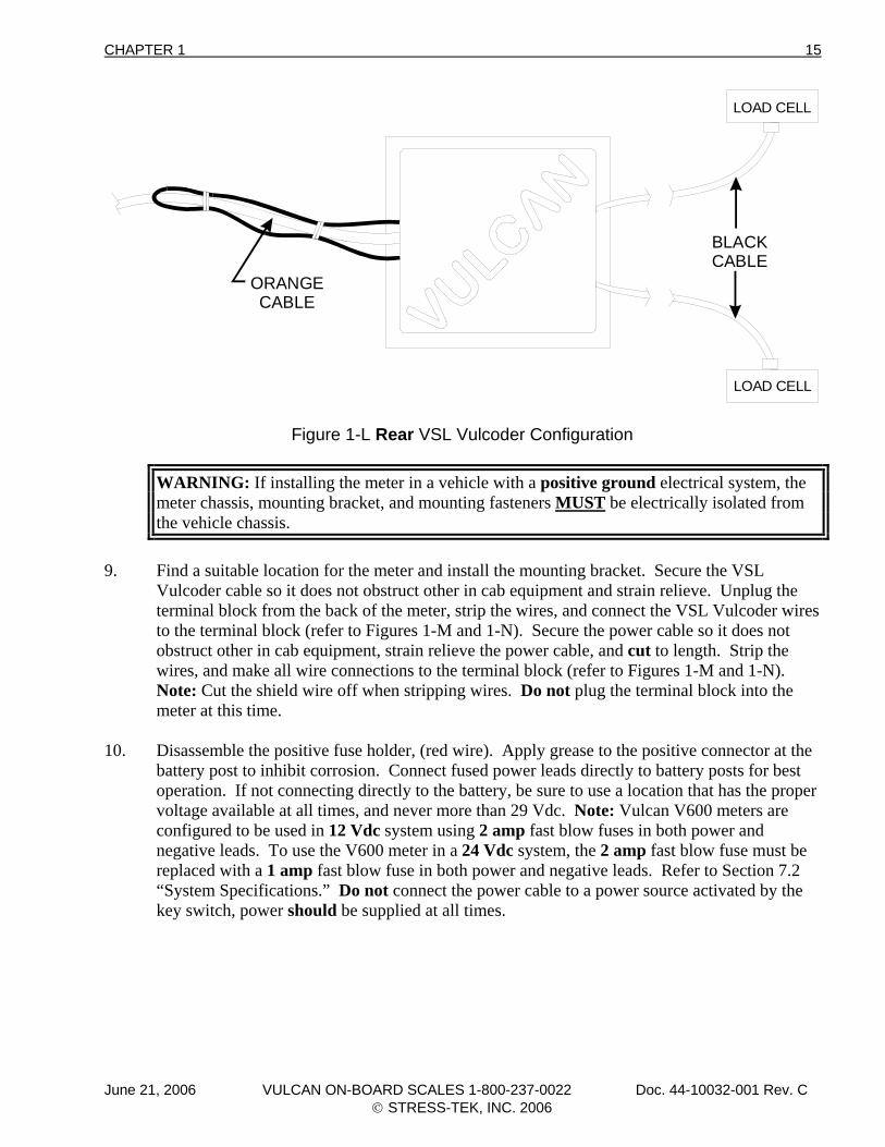
Figure 1-L Rear VSL Vulcoder Configuration
WARNING: If installing the meter in a vehicle with a positive ground electrical system, the meter chassis, mounting bracket, and mounting fasteners MUST be electrically isolated from the vehicle chassis.
9. Find a suitable location for the meter and install the mounting bracket. Secure the VSL
Vulcoder cable so it does not obstruct other in cab equipment and strain relieve. Unplug the terminal block from the back of the meter, strip the wires, and connect the VSL Vulcoder wires to the terminal block (refer to Figures 1-M and 1-N). Secure the power cable so it does not obstruct other in cab equipment, strain relieve the power cable, and cut to length. Strip the wires, and make all wire connections to the terminal block (refer to Figures 1-M and 1-N). Note: Cut the shield wire off when stripping wires. Do not plug the terminal block into the meter at this time.
10. Disassemble the positive fuse holder, (red wire). Apply grease to the positive connector at the
battery post to inhibit corrosion. Connect fused power leads directly to battery posts for best operation. If not connecting directly to the battery, be sure to use a location that has the proper voltage available at all times, and never more than 29 Vdc. Note: Vulcan V600 meters are configured to be used in 12 Vdc system using 2 amp fast blow fuses in both power and negative leads. To use the V600 meter in a 24 Vdc system, the 2 amp fast blow fuse must be replaced with a 1 amp fast blow fuse in both power and negative leads. Refer to Section 7.2 “System Specifications.” Do not connect the power cable to a power source activated by the key switch, power should be supplied at all times.
June 21, 2006 VULCAN ON-BOARD SCALES 1-800-237-0022 Doc. 44-10032-001 Rev. C © STRESS-TEK, INC. 2006
16 CHAPTER 1
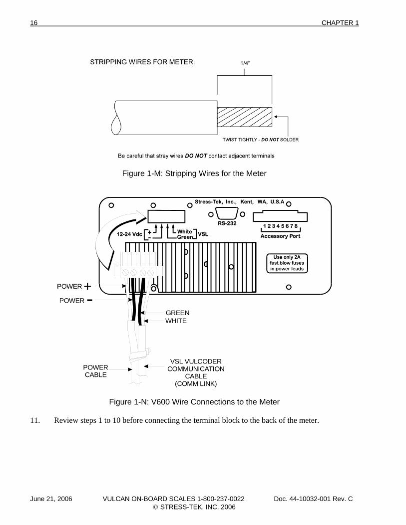
Figure 1-M: Stripping Wires for the Meter
Stress-Tek, Inc., Kent, WA, U.S.A
12-24 Vdc WhiteGreen VSL Accessory Port
RS-232 1 2 3 4 5 6 7 8
+-
VSL VULCODERCOMMUNICATION
CABLE(COMM LINK)
POWERCABLE
POWER
POWER
GREENWHITE
+
Figure 1-N: V600 Wire Connections to the Meter 11. Review steps 1 to 10 before connecting the terminal block to the back of the meter.
June 21, 2006 VULCAN ON-BOARD SCALES 1-800-237-0022 Doc. 44-10032-001 Rev. C © STRESS-TEK, INC. 2006
CHAPTER 2 17
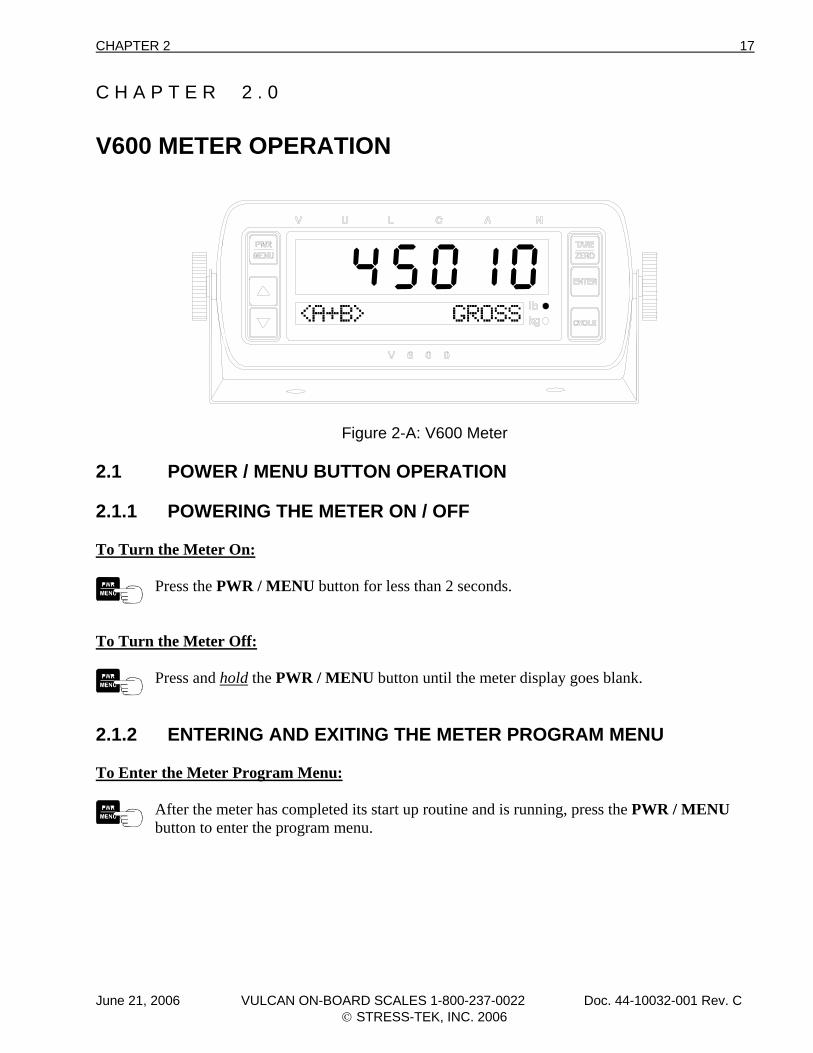
C H A P T E R 2 . 0 V600 METER OPERATION
Figure 2-A: V600 Meter 2.1 POWER / MENU BUTTON OPERATION 2.1.1 POWERING THE METER ON / OFF To Turn the Meter On:
Press the PWR / MENU button for less than 2 seconds.
To Turn the Meter Off:
Press and hold the PWR / MENU button until the meter display goes blank.
2.1.2 ENTERING AND EXITING THE METER PROGRAM MENU To Enter the Meter Program Menu:
After the meter has completed its start up routine and is running, press the PWR / MENU button to enter the program menu.
June 21, 2006 VULCAN ON-BOARD SCALES 1-800-237-0022 Doc. 44-10032-001 Rev. C © STRESS-TEK, INC. 2006
18 CHAPTER 2
To Exit the Meter Program Menu:
Press the PWR / MENU button to exit from the program menu at any time to return to the normal operating mode.
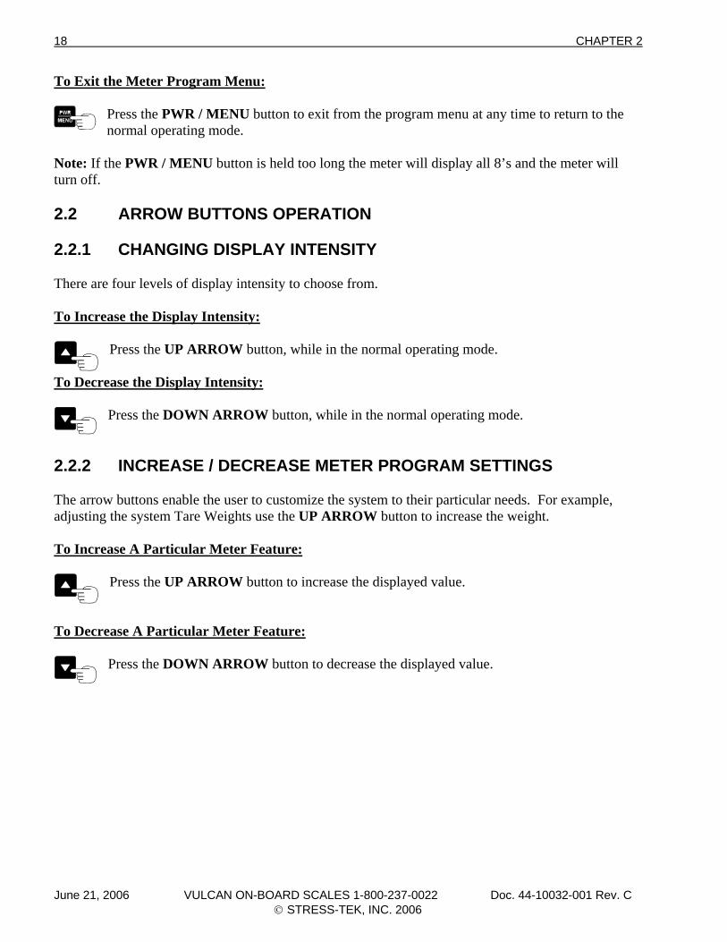
Note: If the PWR / MENU button is held too long the meter will display all 8’s and the meter will turn off. 2.2 ARROW BUTTONS OPERATION 2.2.1 CHANGING DISPLAY INTENSITY There are four levels of display intensity to choose from. To Increase the Display Intensity:
Press the UP ARROW button, while in the normal operating mode.
To Decrease the Display Intensity:
Press the DOWN ARROW button, while in the normal operating mode.
2.2.2 INCREASE / DECREASE METER PROGRAM SETTINGS The arrow buttons enable the user to customize the system to their particular needs. For example, adjusting the system Tare Weights use the UP ARROW button to increase the weight. To Increase A Particular Meter Feature:
Press the UP ARROW button to increase the displayed value.
To Decrease A Particular Meter Feature:
Press the DOWN ARROW button to decrease the displayed value.
June 21, 2006 VULCAN ON-BOARD SCALES 1-800-237-0022 Doc. 44-10032-001 Rev. C © STRESS-TEK, INC. 2006
CHAPTER 2 19
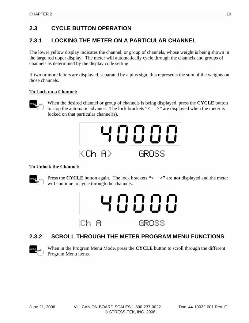
2.3 CYCLE BUTTON OPERATION 2.3.1 LOCKING THE METER ON A PARTICULAR CHANNEL The lower yellow display indicates the channel, or group of channels, whose weight is being shown in the large red upper display. The meter will automatically cycle through the channels and groups of channels as determined by the display code setting. If two or more letters are displayed, separated by a plus sign, this represents the sum of the weights on those channels. To Lock on a Channel:
When the desired channel or group of channels is being displayed, press the CYCLE button to stop the automatic advance. The lock brackets “< >” are displayed when the meter is
locked on that particular channel(s).
To Unlock the Channel:
Press the CYCLE button again. The lock brackets “< >” are not displayed and the meter will continue to cycle through the channels.
2.3.2 SCROLL THROUGH THE METER PROGRAM MENU FUNCTIONS
When in the Program Menu Mode, press the CYCLE button to scroll through the different Program Menu items.
June 21, 2006 VULCAN ON-BOARD SCALES 1-800-237-0022 Doc. 44-10032-001 Rev. C © STRESS-TEK, INC. 2006
20 CHAPTER 2
2.4 ENTER BUTTON OPERATION 2.4.1 SELECTS / ENTERS PROGRAM MENU ITEMS
Press the ENTER button to select the desired main program menu item when it is shown in the lower display. For example, press the ENTER button to select the CONFIGURE
SYSTEM Menu after entering the Program Menu.
2.4.2 STORES NEWLY ADJUSTED METER SETTINGS
Press the ENTER button to store the newly adjusted settings. For example, after making adjustments to the weight mode, press the ENTER button to store the desired setting and
return to the CONF: WT. MODE Menu option. 2.4.3 DISPLAYS TIME AND DATE To Display The Time And Date:
While the meter is in the normal operating mode, press and hold the ENTER button until the current time and date is displayed. The meter will continue to display the time until the
ENTER button is pressed and held again. The meter will return to the normal weight display.
2.4.4 PRINTS A WEIGHT TICKET To Print A Weight Ticket:
While the meter is in the normal operating mode and the RS232 port is configured for a printer, press the ENTER button to print a weight ticket.
June 21, 2006 VULCAN ON-BOARD SCALES 1-800-237-0022 Doc. 44-10032-001 Rev. C © STRESS-TEK, INC. 2006
CHAPTER 2 21
2.5 TARE / ZERO BUTTON OPERATION 2.5.1 ZEROES METER VALUES This feature is very useful when entering various numeric values. The meter will automatically zero the displayed value when the TARE / ZERO button is pressed. For example, this can be used when entering Tare Weights, Set Point values, AZT Range, etc. To Adjust Meter input values to Zero:
Press the TARE / ZERO button to adjust the desired values to zero.
2.5.2 ZEROES METER DISPLAY IN THE "PICK-UP / DELIVERY MODE" The Tare / Zero Button function enables the user to automatically zero the display for each channel, at any time during normal operation. Refer to Section 3.2.1 to set the Weight Mode to Pick-up / Delivery. To Zero The Meter Display:
Press the TARE / ZERO button to zero the meter display during normal operation. Note: The Tare / Zero button will only zero a channel or combination of channels when
locked on that particular channel or combination of channels. 2.5.3 DISPLAYS GROSS WEIGHT IN THE NET AND PICK-UP / DELIVERY MODES The Tare / Zero Button function enables the user to check the total gross weight while being in the Net or Pick-up / Delivery Modes. The gross weight will be displayed on the smaller alpha-numeric display. Note: If in the Pick-up / Delivery mode and locked on a channel or combination of channels, this will also zero what is on the large display. If the meter is in the cycle mode, the gross weight will be displayed without zeroing the upper display. To Display The Total Gross Weight While In The Net or Pick-up / Delivery Modes:
Press and hold the TARE / ZERO button to display the total gross weight on the smaller display without switching to the gross weight mode.
June 21, 2006 VULCAN ON-BOARD SCALES 1-800-237-0022 Doc. 44-10032-001 Rev. C © STRESS-TEK, INC. 2006
22 CHAPTER 2
2.6 VULCODER UPDATING After adjustments have been made to the meter’s set-up, tare or calibration values, the meter will update the Vulcoders with the new information while displaying “WAIT . . .”. Note: Do not power off the meter while it is updating the Vulcoders.
June 21, 2006 VULCAN ON-BOARD SCALES 1-800-237-0022 Doc. 44-10032-001 Rev. C © STRESS-TEK, INC. 2006
CHAPTER 3 23
C H A P T E R 3 . 0 V600 - PROGRAM MENU (SYSTEM SETUP) 3.1 ENTERING THE PROGRAM MENU The V600 meter program menu enables the user to: • Configure System - Selects user configuration fields, allowing system flexibility and customizing
of the configuration items listed:, (Section 3.2) • Weight Mode (Conf: Wt. Mode) - Configures the weight mode, either Gross, Net, or
Pickup/Delivery, (Section 3.2.1). • Display Code (Conf: Disp Code) - Configures the program code, telling the meter what
channels and combination of channels to display, (Section 3.2.2). • Set Point (Conf: Set Points) - Configures the set points, (Section 3.2.3) • Cycle Time (Conf: Cycle Time) - Configures the channel cycle time, (Section 3.2.4). • RS 232 Port (Conf: RS232 Port) - Configures the data format of the RS 232
communications port, (Section 3.2.5). • Print Headers (Conf: Print Hdrs) - Configures customized print headings used when
printing weight tickets, (Section 3.2.6). • Date (Conf: Date) - Configures the current date, (Section 3.2.7). • Time (Conf: Time) - Configures the current time, (Section 3.2.8). • Scale ID (Conf: Scale ID) - Configures the scale or truck ID associated with currently
used V600 system, (Section 3.2.9). • Lock (Conf: Lock) - Configures the Setup / Calibration Lock. The lock must be in the Off
position to adjust the Tare or Calibration settings for the scale. Turning the lock to the On position will prevent changes to the system’s calibration, (Section 3.2.10).
• Setup / Calibration - Selects the system setup and calibration (Section 3.3), items listed:, (Section 3.3)
• Tare Weight (Set: Tare Weight) - Sets the desired tare weight (Empty Weight) of each active channel, (Section 3.3.1).
• Cal Number (Set: Cal Number) - Sets the calibration number for each active channel, (Section 3.3.2).
• Full Weight (Set: Full Weight) - Sets the projected full, calibrated weight for each active channel, (Section 3.3.3).
• Post Cal (Set: Post Cal) - Sets the system calibration after the load is emptied for each active channel, (Section 3.3.4).
• Grad Size (Set: Grad Size) - Sets the graduation for displaying weight, (Section 3.3.5). • Units (Set: Units) - Sets the units of measure, either pounds or kilograms, (Section 3.3.6). • Auto Zero Tracking (Set: AZT Range) - Sets the auto zero tracking range for each active
channel, (Section 3.3.7)
June 21, 2006 VULCAN ON-BOARD SCALES 1-800-237-0022 Doc. 44-10032-001 Rev. C © STRESS-TEK, INC. 2006
24 CHAPTER 3
• Sample Size (Set: Sample Size) - Sets the number of weight readings averaged before displaying a weight, i.e. the higher the number, the more the readings are filtered. The higher filtering is needed when there is movement during the weighing process, (Section 3.3.8).
• Sequence Chanls - Assigns the proper sequence to the Vulcoders in the system, (Section 3.4). • System Test Menu - Selects the diagnostic system test, (Section 3.5). To Enter the Meter Program Menu:
Press the PWR / MENU button to turn on the meter.
After the meter has completed its start up routine and is running, press the PWR / MENU button to enter the program menu.
Press the CYCLE button to go through the four different main program items: Configure System, Setup / Calibration, Sequence Chanls, and System Test.
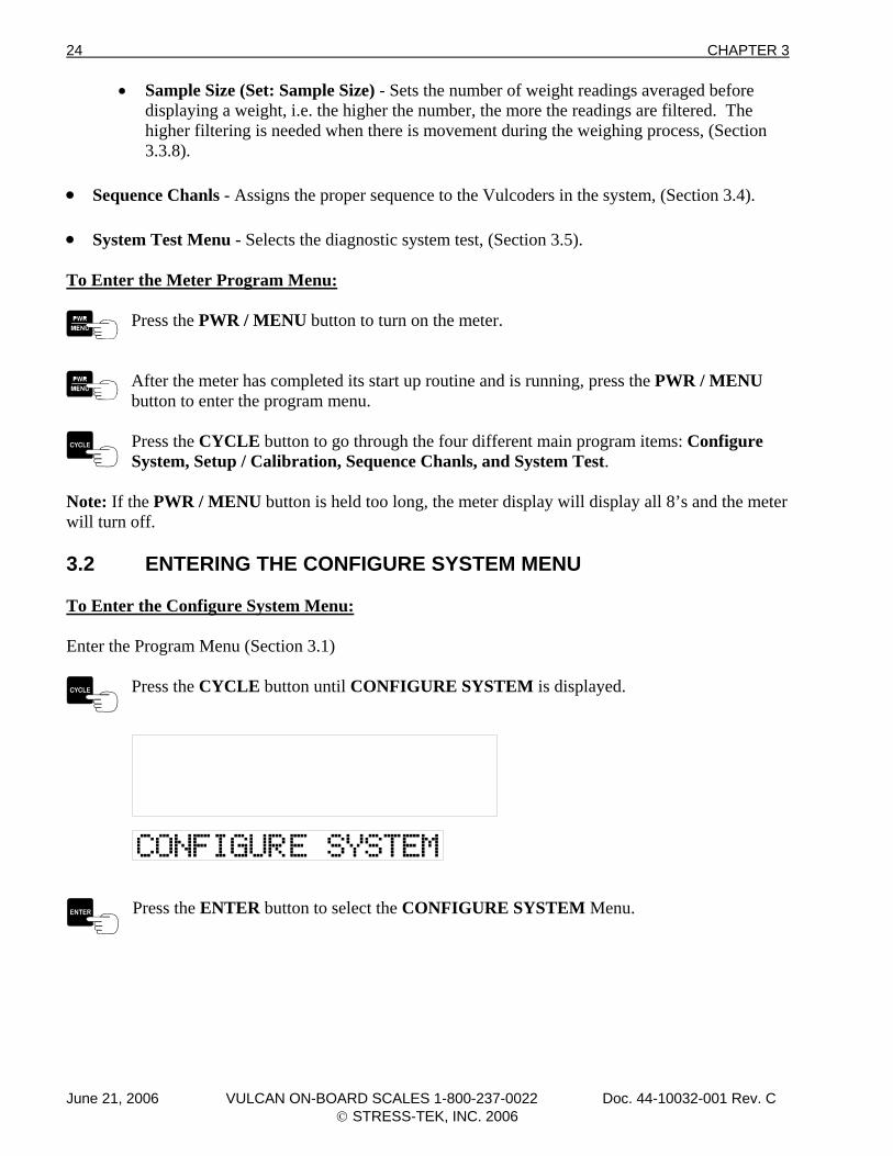
Note: If the PWR / MENU button is held too long, the meter display will display all 8’s and the meter will turn off. 3.2 ENTERING THE CONFIGURE SYSTEM MENU To Enter the Configure System Menu: Enter the Program Menu (Section 3.1)
Press the CYCLE button until CONFIGURE SYSTEM is displayed.
Press the ENTER button to select the CONFIGURE SYSTEM Menu.
June 21, 2006 VULCAN ON-BOARD SCALES 1-800-237-0022 Doc. 44-10032-001 Rev. C © STRESS-TEK, INC. 2006
CHAPTER 3 25
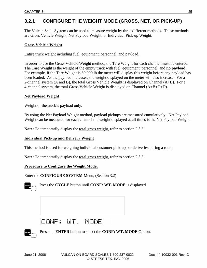
3.2.1 CONFIGURE THE WEIGHT MODE (GROSS, NET, OR PICK-UP) The Vulcan Scale System can be used to measure weight by three different methods. These methods are Gross Vehicle Weight, Net Payload Weight, or Individual Pick-up Weight. Gross Vehicle Weight Entire truck weight including fuel, equipment, personnel, and payload. In order to use the Gross Vehicle Weight method, the Tare Weight for each channel must be entered. The Tare Weight is the weight of the empty truck with fuel, equipment, personnel, and no payload. For example, if the Tare Weight is 30,000 lb the meter will display this weight before any payload has been loaded. As the payload increases, the weight displayed on the meter will also increase. For a 2-channel system (A and B), the total Gross Vehicle Weight is displayed on Channel (A+B). For a 4-channel system, the total Gross Vehicle Weight is displayed on Channel (A+B+C+D). Net Payload Weight Weight of the truck’s payload only. By using the Net Payload Weight method, payload pickups are measured cumulatively. Net Payload Weight can be measured for each channel the weight displayed at all times is the Net Payload Weight. Note: To temporarily display the total gross weight, refer to section 2.5.3. Individual Pick-up and Delivery Weight This method is used for weighing individual customer pick-ups or deliveries during a route. Note: To temporarily display the total gross weight, refer to section 2.5.3. Procedure to Configure the Weight Mode: Enter the CONFIGURE SYSTEM Menu, (Section 3.2)
Press the CYCLE button until CONF: WT. MODE is displayed.
Press the ENTER button to select the CONF: WT. MODE Option.
June 21, 2006 VULCAN ON-BOARD SCALES 1-800-237-0022 Doc. 44-10032-001 Rev. C © STRESS-TEK, INC. 2006
26 CHAPTER 3
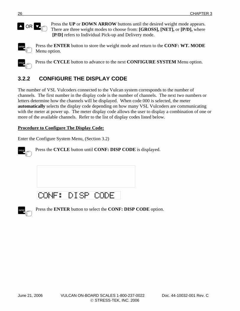
Press the UP or DOWN ARROW buttons until the desired weight mode appears. There are three weight modes to choose from: [GROSS], [NET], or [P/D], where
[P/D] refers to Individual Pick-up and Delivery mode.
Press the ENTER button to store the weight mode and return to the CONF: WT. MODE Menu option.
Press the CYCLE button to advance to the next CONFIGURE SYSTEM Menu option.
3.2.2 CONFIGURE THE DISPLAY CODE The number of VSL Vulcoders connected to the Vulcan system corresponds to the number of channels. The first number in the display code is the number of channels. The next two numbers or letters determine how the channels will be displayed. When code 000 is selected, the meter automatically selects the display code depending on how many VSL Vulcoders are communicating with the meter at power up. The meter display code allows the user to display a combination of one or more of the available channels. Refer to the list of display codes listed below. Procedure to Configure The Display Code: Enter the Configure System Menu, (Section 3.2)
Press the CYCLE button until CONF: DISP CODE is displayed.
Press the ENTER button to select the CONF: DISP CODE option.
June 21, 2006 VULCAN ON-BOARD SCALES 1-800-237-0022 Doc. 44-10032-001 Rev. C © STRESS-TEK, INC. 2006
CHAPTER 3 27
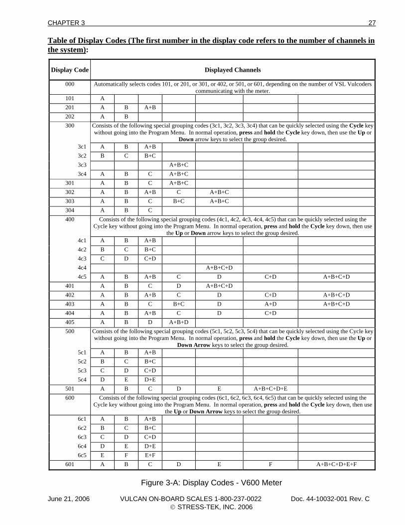
Table of Display Codes (The first number in the display code refers to the number of channels in the system):
Display Code
Displayed Channels
000 Automatically selects codes 101, or 201, or 301, or 402, or 501, or 601, depending on the number of VSL Vulcoders communicating with the meter.
101 A 201 A B A+B 202 A B 300 Consists of the following special grouping codes (3c1, 3c2, 3c3, 3c4) that can be quickly selected using the Cycle key
without going into the Program Menu. In normal operation, press and hold the Cycle key down, then use the Up or Down arrow keys to select the group desired.
3c1 A B A+B 3c2 B C B+C 3c3 A+B+C 3c4 A B C A+B+C
301 A B C A+B+C 302 A B A+B C A+B+C 303 A B C B+C A+B+C 304 A B C 400 Consists of the following special grouping codes (4c1, 4c2, 4c3, 4c4, 4c5) that can be quickly selected using the
Cycle key without going into the Program Menu. In normal operation, press and hold the Cycle key down, then use the Up or Down arrow keys to select the group desired.
4c1 A B A+B 4c2 B C B+C 4c3 C D C+D 4c4 A+B+C+D 4c5 A B A+B C D C+D A+B+C+D
401 A B C D A+B+C+D 402 A B A+B C D C+D A+B+C+D 403 A B C B+C D A+D A+B+C+D 404 A B A+B C D C+D 405 A B D A+B+D 500 Consists of the following special grouping codes (5c1, 5c2, 5c3, 5c4) that can be quickly selected using the Cycle key
without going into the Program Menu. In normal operation, press and hold the Cycle key down, then use the Up or Down Arrow keys to select the group desired.
5c1 A B A+B 5c2 B C B+C 5c3 C D C+D 5c4 D E D+E
501 A B C D E A+B+C+D+E 600 Consists of the following special grouping codes (6c1, 6c2, 6c3, 6c4, 6c5) that can be quickly selected using the
Cycle key without going into the Program Menu. In normal operation, press and hold the Cycle key down, then use the Up or Down Arrow keys to select the group desired.
6c1 A B A+B 6c2 B C B+C 6c3 C D C+D 6c4 D E D+E 6c5 E F E+F
601 A B C D E F A+B+C+D+E+F
Figure 3-A: Display Codes - V600 Meter
June 21, 2006 VULCAN ON-BOARD SCALES 1-800-237-0022 Doc. 44-10032-001 Rev. C © STRESS-TEK, INC. 2006
28 CHAPTER 3
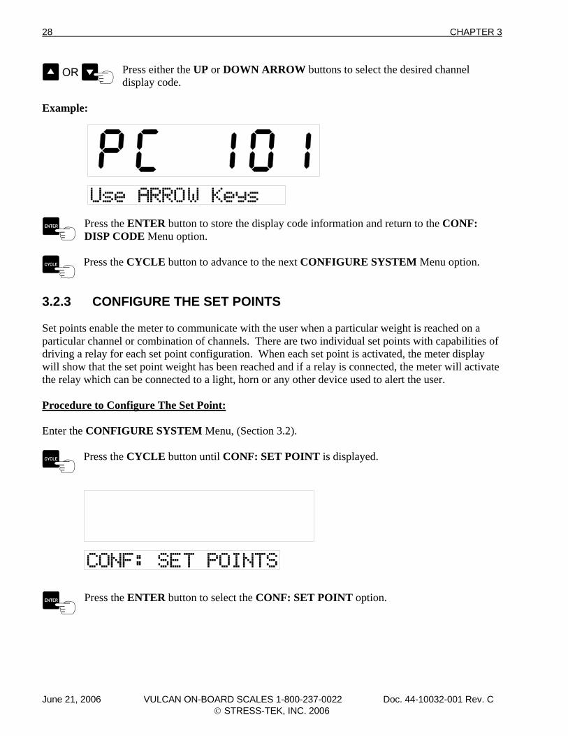
Press either the UP or DOWN ARROW buttons to select the desired channel display code.
Example:
Press the ENTER button to store the display code information and return to the CONF: DISP CODE Menu option.
Press the CYCLE button to advance to the next CONFIGURE SYSTEM Menu option.
3.2.3 CONFIGURE THE SET POINTS Set points enable the meter to communicate with the user when a particular weight is reached on a particular channel or combination of channels. There are two individual set points with capabilities of driving a relay for each set point configuration. When each set point is activated, the meter display will show that the set point weight has been reached and if a relay is connected, the meter will activate the relay which can be connected to a light, horn or any other device used to alert the user. Procedure to Configure The Set Point: Enter the CONFIGURE SYSTEM Menu, (Section 3.2).
Press the CYCLE button until CONF: SET POINT is displayed.
Press the ENTER button to select the CONF: SET POINT option.
June 21, 2006 VULCAN ON-BOARD SCALES 1-800-237-0022 Doc. 44-10032-001 Rev. C © STRESS-TEK, INC. 2006
CHAPTER 3 29
Configure Set Point - Selects user set point configuration fields, allowing flexibility and customizing of the set point configuration items listed:
• Configuration of Relay 1 (Conf: RELAY 1) - Configures the set point to activate relay 1, (Section 3.2.3A).
• Configuration of Relay 2 (Conf: RELAY 2) - Configures the set point to activate relay 2, (Section 3.2.3B).
• Configuration of Delta Weight (Conf: DELTA WT.) - Configures the set point Delta Weight, (Section 3.2.3C).
• Configuration of On Time (Conf: ON TIME) - Configures the set point activation On Time, (Section 3.2.3D).
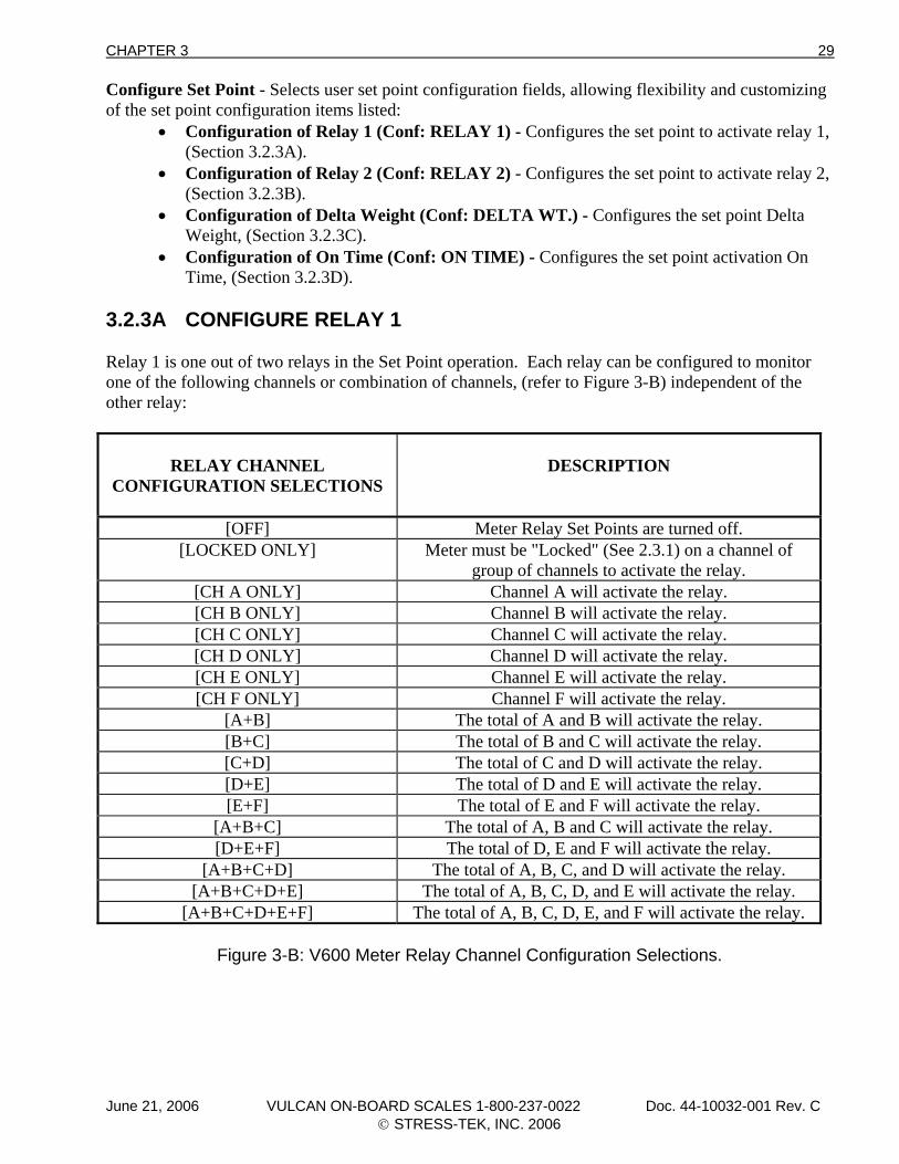
3.2.3A CONFIGURE RELAY 1 Relay 1 is one out of two relays in the Set Point operation. Each relay can be configured to monitor one of the following channels or combination of channels, (refer to Figure 3-B) independent of the other relay:
RELAY CHANNEL
CONFIGURATION SELECTIONS
DESCRIPTION
[OFF] Meter Relay Set Points are turned off. [LOCKED ONLY] Meter must be "Locked" (See 2.3.1) on a channel of
group of channels to activate the relay. [CH A ONLY] Channel A will activate the relay. [CH B ONLY] Channel B will activate the relay. [CH C ONLY] Channel C will activate the relay. [CH D ONLY] Channel D will activate the relay. [CH E ONLY] Channel E will activate the relay. [CH F ONLY] Channel F will activate the relay.
[A+B] The total of A and B will activate the relay. [B+C] The total of B and C will activate the relay. [C+D] The total of C and D will activate the relay. [D+E] The total of D and E will activate the relay. [E+F] The total of E and F will activate the relay.
[A+B+C] The total of A, B and C will activate the relay. [D+E+F] The total of D, E and F will activate the relay.
[A+B+C+D] The total of A, B, C, and D will activate the relay. [A+B+C+D+E] The total of A, B, C, D, and E will activate the relay.
[A+B+C+D+E+F] The total of A, B, C, D, E, and F will activate the relay.
Figure 3-B: V600 Meter Relay Channel Configuration Selections.
June 21, 2006 VULCAN ON-BOARD SCALES 1-800-237-0022 Doc. 44-10032-001 Rev. C © STRESS-TEK, INC. 2006
30 CHAPTER 3
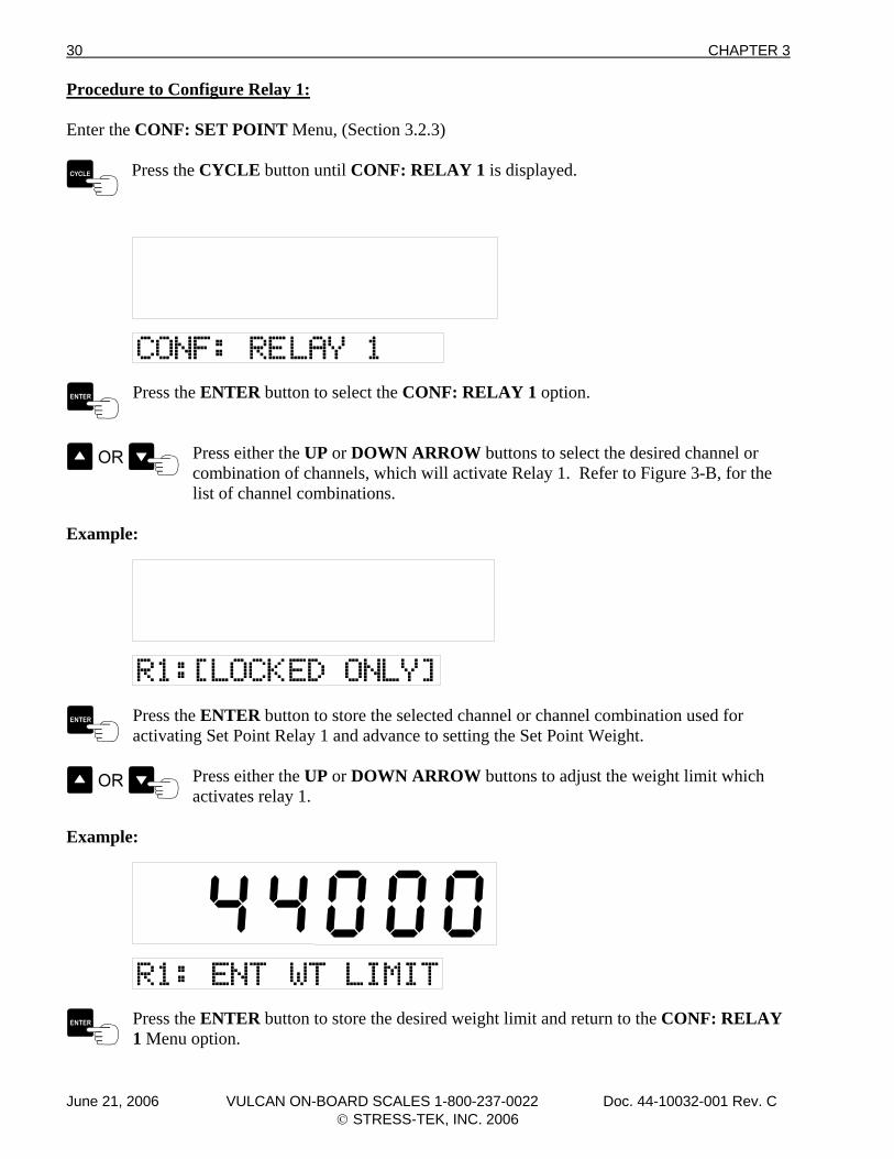
Procedure to Configure Relay 1: Enter the CONF: SET POINT Menu, (Section 3.2.3)
Press the CYCLE button until CONF: RELAY 1 is displayed.
Press the ENTER button to select the CONF: RELAY 1 option.
Press either the UP or DOWN ARROW buttons to select the desired channel or combination of channels, which will activate Relay 1. Refer to Figure 3-B, for the
list of channel combinations.
Example:
Press the ENTER button to store the selected channel or channel combination used for activating Set Point Relay 1 and advance to setting the Set Point Weight.
Press either the UP or DOWN ARROW buttons to adjust the weight limit which activates relay 1.
Example:
Press the ENTER button to store the desired weight limit and return to the CONF: RELAY 1 Menu option.
June 21, 2006 VULCAN ON-BOARD SCALES 1-800-237-0022 Doc. 44-10032-001 Rev. C © STRESS-TEK, INC. 2006
CHAPTER 3 31
Press the CYCLE button to advance to the next Set Point Menu option.
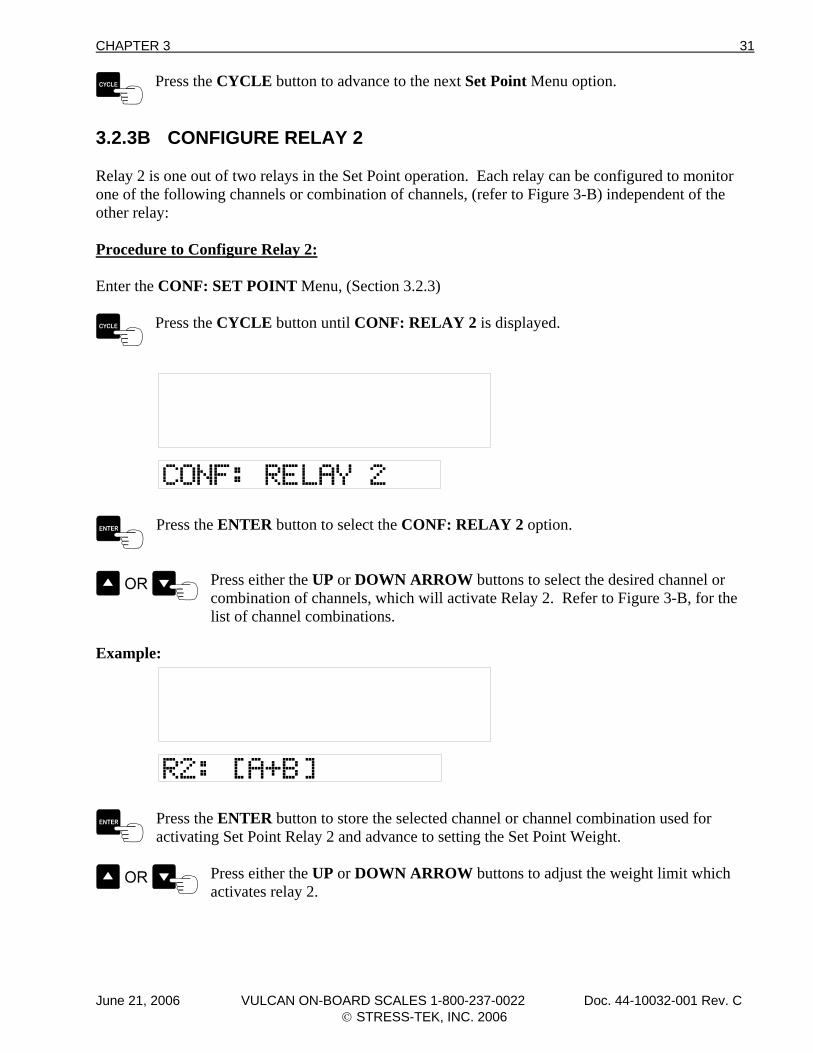
3.2.3B CONFIGURE RELAY 2 Relay 2 is one out of two relays in the Set Point operation. Each relay can be configured to monitor one of the following channels or combination of channels, (refer to Figure 3-B) independent of the other relay: Procedure to Configure Relay 2: Enter the CONF: SET POINT Menu, (Section 3.2.3)
Press the CYCLE button until CONF: RELAY 2 is displayed.
Press the ENTER button to select the CONF: RELAY 2 option.
Press either the UP or DOWN ARROW buttons to select the desired channel or combination of channels, which will activate Relay 2. Refer to Figure 3-B, for the
list of channel combinations.
Example:
Press the ENTER button to store the selected channel or channel combination used for activating Set Point Relay 2 and advance to setting the Set Point Weight.
Press either the UP or DOWN ARROW buttons to adjust the weight limit which activates relay 2.
June 21, 2006 VULCAN ON-BOARD SCALES 1-800-237-0022 Doc. 44-10032-001 Rev. C © STRESS-TEK, INC. 2006
32 CHAPTER 3
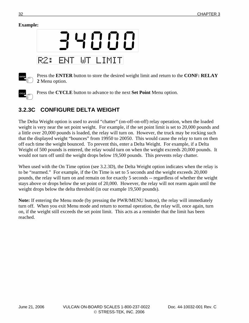
Example:
Press the ENTER button to store the desired weight limit and return to the CONF: RELAY 2 Menu option.
Press the CYCLE button to advance to the next Set Point Menu option.
3.2.3C CONFIGURE DELTA WEIGHT The Delta Weight option is used to avoid “chatter” (on-off-on-off) relay operation, when the loaded weight is very near the set point weight. For example, if the set point limit is set to 20,000 pounds and a little over 20,000 pounds is loaded, the relay will turn on. However, the truck may be rocking such that the displayed weight “bounces” from 19950 to 20050. This would cause the relay to turn on then off each time the weight bounced. To prevent this, enter a Delta Weight. For example, if a Delta Weight of 500 pounds is entered, the relay would turn on when the weight exceeds 20,000 pounds. It would not turn off until the weight drops below 19,500 pounds. This prevents relay chatter. When used with the On Time option (see 3.2.3D), the Delta Weight option indicates when the relay is to be “rearmed.” For example, if the On Time is set to 5 seconds and the weight exceeds 20,000 pounds, the relay will turn on and remain on for exactly 5 seconds -- regardless of whether the weight stays above or drops below the set point of 20,000. However, the relay will not rearm again until the weight drops below the delta threshold (in our example 19,500 pounds). Note: If entering the Menu mode (by pressing the PWR/MENU button), the relay will immediately turn off. When you exit Menu mode and return to normal operation, the relay will, once again, turn on, if the weight still exceeds the set point limit. This acts as a reminder that the limit has been reached.
June 21, 2006 VULCAN ON-BOARD SCALES 1-800-237-0022 Doc. 44-10032-001 Rev. C © STRESS-TEK, INC. 2006
CHAPTER 3 33
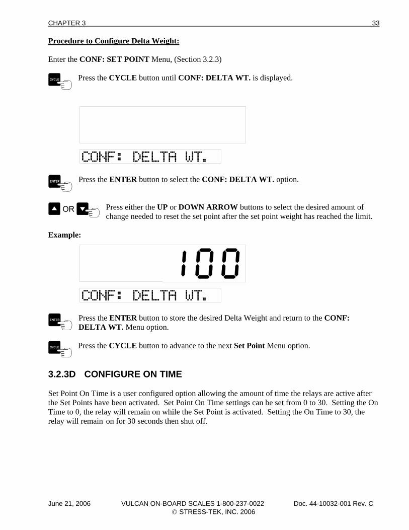
Procedure to Configure Delta Weight: Enter the CONF: SET POINT Menu, (Section 3.2.3)
Press the CYCLE button until CONF: DELTA WT. is displayed.
Press the ENTER button to select the CONF: DELTA WT. option.
Press either the UP or DOWN ARROW buttons to select the desired amount of change needed to reset the set point after the set point weight has reached the limit.
Example:
Press the ENTER button to store the desired Delta Weight and return to the CONF: DELTA WT. Menu option.
Press the CYCLE button to advance to the next Set Point Menu option.
3.2.3D CONFIGURE ON TIME Set Point On Time is a user configured option allowing the amount of time the relays are active after the Set Points have been activated. Set Point On Time settings can be set from 0 to 30. Setting the On Time to 0, the relay will remain on while the Set Point is activated. Setting the On Time to 30, the relay will remain on for 30 seconds then shut off.
June 21, 2006 VULCAN ON-BOARD SCALES 1-800-237-0022 Doc. 44-10032-001 Rev. C © STRESS-TEK, INC. 2006
34 CHAPTER 3
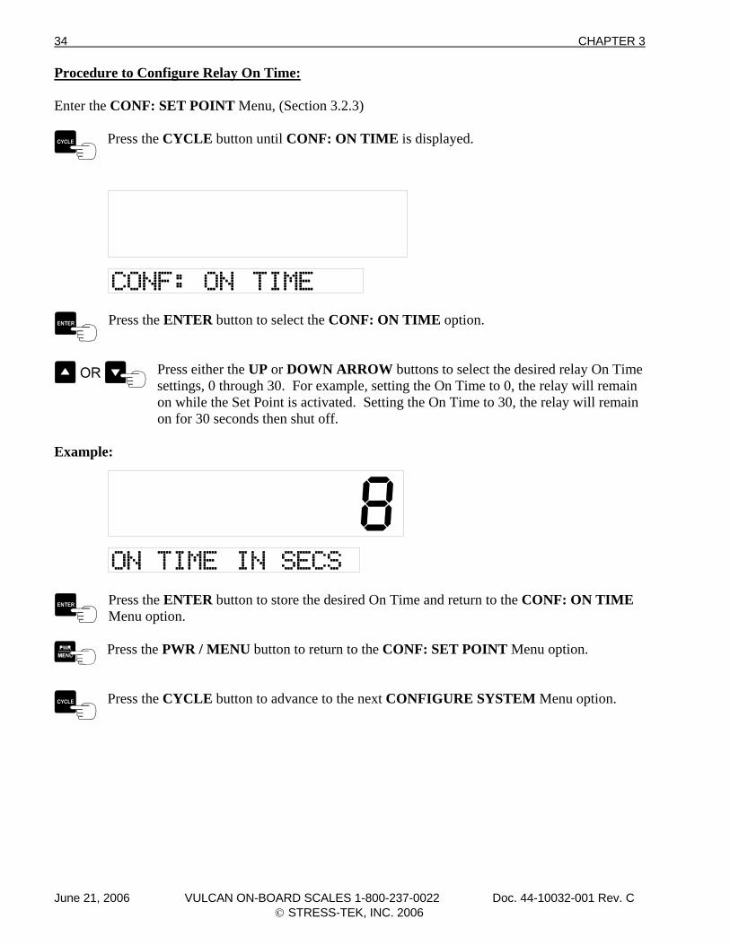
Procedure to Configure Relay On Time: Enter the CONF: SET POINT Menu, (Section 3.2.3)
Press the CYCLE button until CONF: ON TIME is displayed.
Press the ENTER button to select the CONF: ON TIME option.
Press either the UP or DOWN ARROW buttons to select the desired relay On Time settings, 0 through 30. For example, setting the On Time to 0, the relay will remain
on while the Set Point is activated. Setting the On Time to 30, the relay will remain on for 30 seconds then shut off.
Example:
Press the ENTER button to store the desired On Time and return to the CONF: ON TIME Menu option.
Press the PWR / MENU button to return to the CONF: SET POINT Menu option.
Press the CYCLE button to advance to the next CONFIGURE SYSTEM Menu option.
June 21, 2006 VULCAN ON-BOARD SCALES 1-800-237-0022 Doc. 44-10032-001 Rev. C © STRESS-TEK, INC. 2006
CHAPTER 3 35
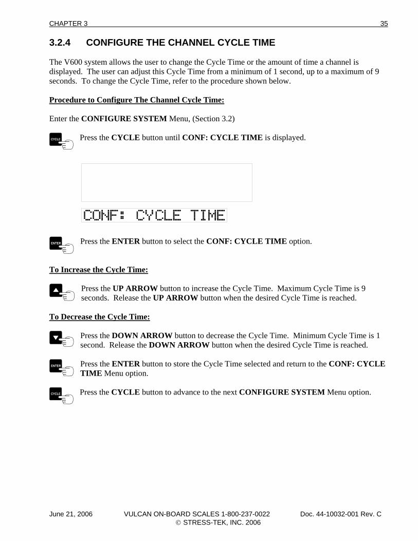
3.2.4 CONFIGURE THE CHANNEL CYCLE TIME The V600 system allows the user to change the Cycle Time or the amount of time a channel is displayed. The user can adjust this Cycle Time from a minimum of 1 second, up to a maximum of 9 seconds. To change the Cycle Time, refer to the procedure shown below. Procedure to Configure The Channel Cycle Time: Enter the CONFIGURE SYSTEM Menu, (Section 3.2)
Press the CYCLE button until CONF: CYCLE TIME is displayed.
Press the ENTER button to select the CONF: CYCLE TIME option.
To Increase the Cycle Time:
Press the UP ARROW button to increase the Cycle Time. Maximum Cycle Time is 9 seconds. Release the UP ARROW button when the desired Cycle Time is reached.
To Decrease the Cycle Time:
Press the DOWN ARROW button to decrease the Cycle Time. Minimum Cycle Time is 1 second. Release the DOWN ARROW button when the desired Cycle Time is reached.
Press the ENTER button to store the Cycle Time selected and return to the CONF: CYCLE TIME Menu option.
Press the CYCLE button to advance to the next CONFIGURE SYSTEM Menu option.
June 21, 2006 VULCAN ON-BOARD SCALES 1-800-237-0022 Doc. 44-10032-001 Rev. C © STRESS-TEK, INC. 2006
36 CHAPTER 3
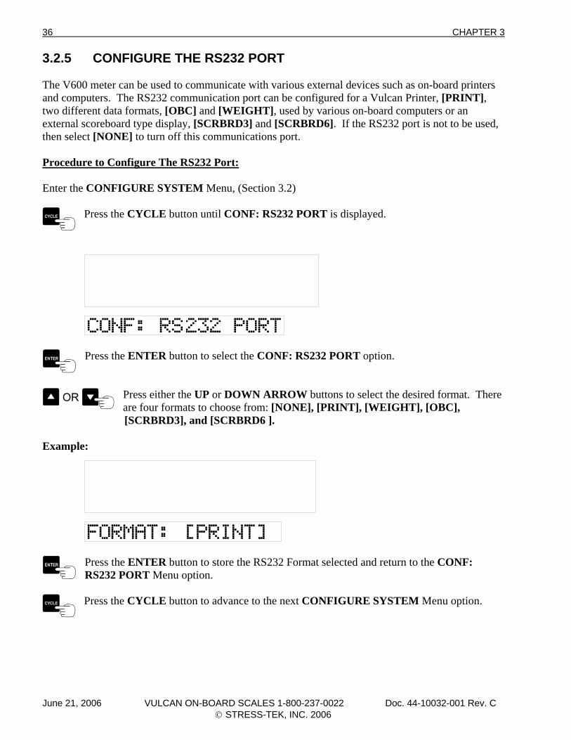
3.2.5 CONFIGURE THE RS232 PORT The V600 meter can be used to communicate with various external devices such as on-board printers and computers. The RS232 communication port can be configured for a Vulcan Printer, [PRINT], two different data formats, [OBC] and [WEIGHT], used by various on-board computers or an external scoreboard type display, [SCRBRD3] and [SCRBRD6]. If the RS232 port is not to be used, then select [NONE] to turn off this communications port. Procedure to Configure The RS232 Port: Enter the CONFIGURE SYSTEM Menu, (Section 3.2)
Press the CYCLE button until CONF: RS232 PORT is displayed.
Press the ENTER button to select the CONF: RS232 PORT option.
Press either the UP or DOWN ARROW buttons to select the desired format. There are four formats to choose from: [NONE], [PRINT], [WEIGHT], [OBC],
[SCRBRD3], and [SCRBRD6 ].
Example:
Press the ENTER button to store the RS232 Format selected and return to the CONF: RS232 PORT Menu option.
Press the CYCLE button to advance to the next CONFIGURE SYSTEM Menu option.
June 21, 2006 VULCAN ON-BOARD SCALES 1-800-237-0022 Doc. 44-10032-001 Rev. C © STRESS-TEK, INC. 2006
CHAPTER 3 37
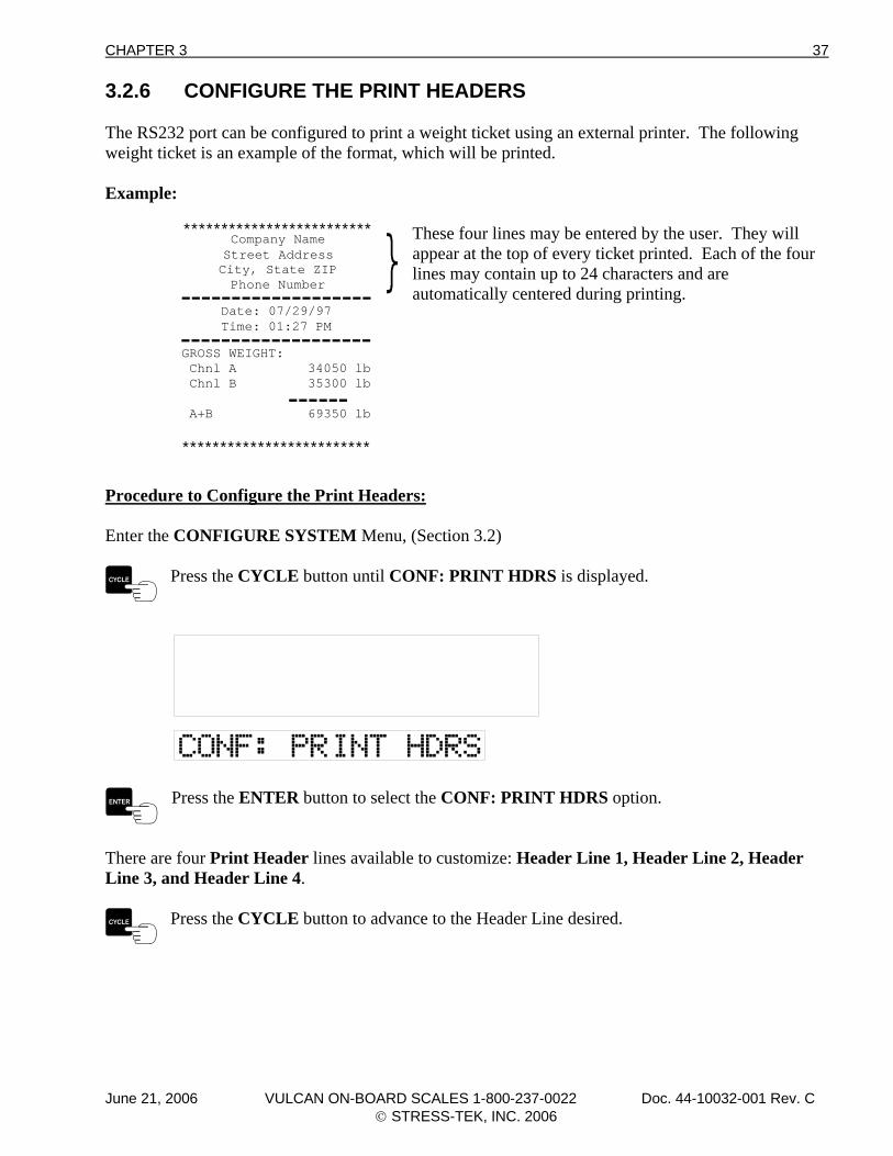
3.2.6 CONFIGURE THE PRINT HEADERS The RS232 port can be configured to print a weight ticket using an external printer. The following weight ticket is an example of the format, which will be printed. Example:
************************* These four lines may be entered by the user. They will
appear at the top of every ticket printed. Each of the four lines may contain up to 24 characters and are automatically centered during printing.
*************************
Date: 07/29/97Time: 01:27 PM
Company NameStreet AddressCity, State ZIPPhone Number-------------------
-------------------
------GROSS WEIGHT: Chnl A 34050 lb Chnl B 35300 lb
A+B 69350 lb
Procedure to Configure the Print Headers: Enter the CONFIGURE SYSTEM Menu, (Section 3.2)
Press the CYCLE button until CONF: PRINT HDRS is displayed.
Press the ENTER button to select the CONF: PRINT HDRS option.
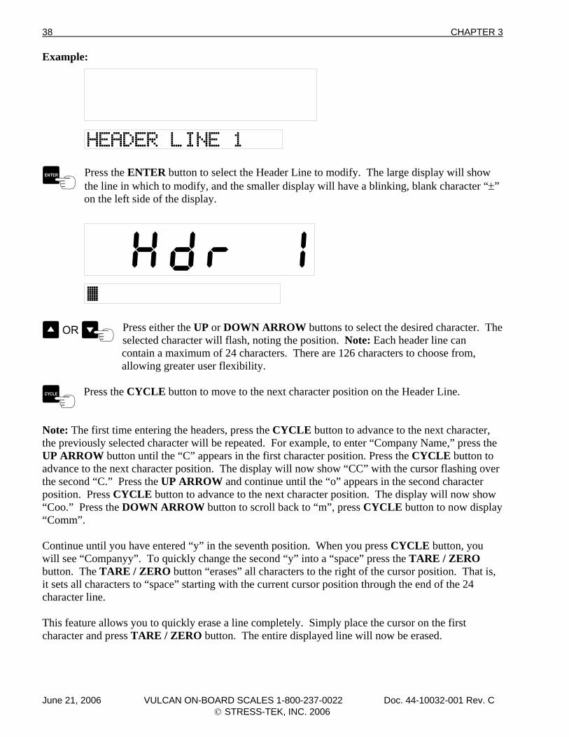
There are four Print Header lines available to customize: Header Line 1, Header Line 2, Header Line 3, and Header Line 4.
Press the CYCLE button to advance to the Header Line desired.
June 21, 2006 VULCAN ON-BOARD SCALES 1-800-237-0022 Doc. 44-10032-001 Rev. C © STRESS-TEK, INC. 2006
38 CHAPTER 3
Example:
Press the ENTER button to select the Header Line to modify. The large display will show the line in which to modify, and the smaller display will have a blinking, blank character “±”
on the left side of the display.
Press either the UP or DOWN ARROW buttons to select the desired character. The selected character will flash, noting the position. Note: Each header line can
contain a maximum of 24 characters. There are 126 characters to choose from, allowing greater user flexibility.
Press the CYCLE button to move to the next character position on the Header Line.
Note: The first time entering the headers, press the CYCLE button to advance to the next character, the previously selected character will be repeated. For example, to enter “Company Name,” press the UP ARROW button until the “C” appears in the first character position. Press the CYCLE button to advance to the next character position. The display will now show “CC” with the cursor flashing over the second “C.” Press the UP ARROW and continue until the “o” appears in the second character position. Press CYCLE button to advance to the next character position. The display will now show “Coo.” Press the DOWN ARROW button to scroll back to “m”, press CYCLE button to now display “Comm”. Continue until you have entered “y” in the seventh position. When you press CYCLE button, you will see “Companyy”. To quickly change the second “y” into a “space” press the TARE / ZERO button. The TARE / ZERO button “erases” all characters to the right of the cursor position. That is, it sets all characters to “space” starting with the current cursor position through the end of the 24 character line. This feature allows you to quickly erase a line completely. Simply place the cursor on the first character and press TARE / ZERO button. The entire displayed line will now be erased.
June 21, 2006 VULCAN ON-BOARD SCALES 1-800-237-0022 Doc. 44-10032-001 Rev. C © STRESS-TEK, INC. 2006
CHAPTER 3 39
Note: If a mistake is made, press the PWR / MENU button to return to the Header Line # menu and cancel any changes to that line. Changes are only made to a Header Line when you press the ENTER button. Repeat the above steps until the text is completed for the selected Header Line.
Press the ENTER button to store the newly configured Header Line. The display will return to the display the header line previously selected.
Press the CYCLE button to advance to the next Header Line.
Press the PWR / MENU button to return to the CONF: PRINT HDRS Menu option.
Press the CYCLE button to advance to the next CONFIGURE SYSTEM Menu option.
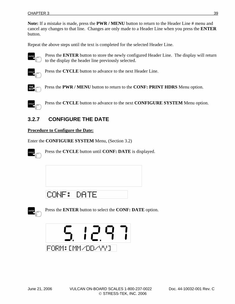
3.2.7 CONFIGURE THE DATE Procedure to Configure the Date: Enter the CONFIGURE SYSTEM Menu, (Section 3.2)
Press the CYCLE button until CONF: DATE is displayed.
Press the ENTER button to select the CONF: DATE option.
June 21, 2006 VULCAN ON-BOARD SCALES 1-800-237-0022 Doc. 44-10032-001 Rev. C © STRESS-TEK, INC. 2006
40 CHAPTER 3
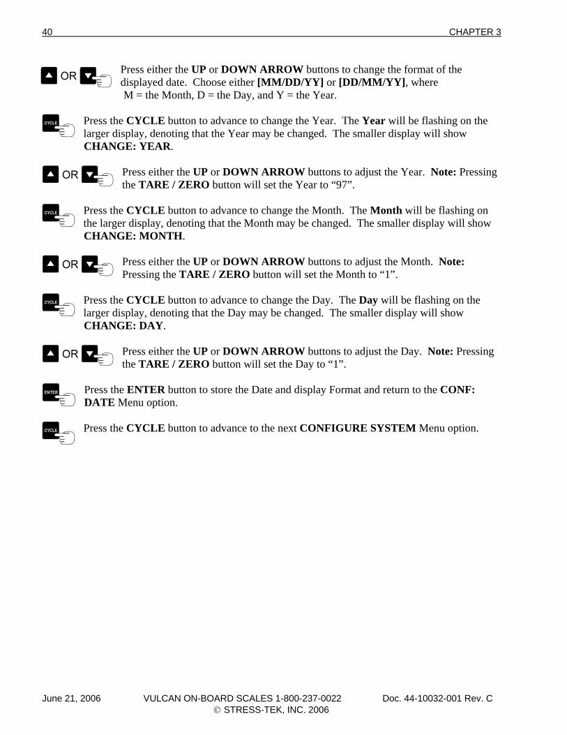
Press either the UP or DOWN ARROW buttons to change the format of the displayed date. Choose either [MM/DD/YY] or [DD/MM/YY], where
M = the Month, D = the Day, and Y = the Year.
Press the CYCLE button to advance to change the Year. The Year will be flashing on the larger display, denoting that the Year may be changed. The smaller display will show
CHANGE: YEAR.
Press either the UP or DOWN ARROW buttons to adjust the Year. Note: Pressing the TARE / ZERO button will set the Year to “97”.
Press the CYCLE button to advance to change the Month. The Month will be flashing on the larger display, denoting that the Month may be changed. The smaller display will show
CHANGE: MONTH.
Press either the UP or DOWN ARROW buttons to adjust the Month. Note: Pressing the TARE / ZERO button will set the Month to “1”.
Press the CYCLE button to advance to change the Day. The Day will be flashing on the larger display, denoting that the Day may be changed. The smaller display will show
CHANGE: DAY.
Press either the UP or DOWN ARROW buttons to adjust the Day. Note: Pressing the TARE / ZERO button will set the Day to “1”.
Press the ENTER button to store the Date and display Format and return to the CONF: DATE Menu option.
Press the CYCLE button to advance to the next CONFIGURE SYSTEM Menu option.
June 21, 2006 VULCAN ON-BOARD SCALES 1-800-237-0022 Doc. 44-10032-001 Rev. C © STRESS-TEK, INC. 2006
CHAPTER 3 41
3.2.8 CONFIGURE THE TIME Procedure to Configure the Time: Enter the CONFIGURE SYSTEM Menu, (Section 3.2)
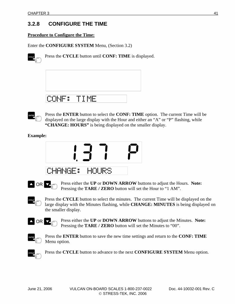
Press the CYCLE button until CONF: TIME is displayed.
Press the ENTER button to select the CONF: TIME option. The current Time will be displayed on the large display with the Hour and either an “A” or “P” flashing, while
“CHANGE: HOURS” is being displayed on the smaller display.
Example:
Press either the UP or DOWN ARROW buttons to adjust the Hours. Note: Pressing the TARE / ZERO button will set the Hour to “1 AM”.
Press the CYCLE button to select the minutes. The current Time will be displayed on the large display with the Minutes flashing, while CHANGE: MINUTES is being displayed on
the smaller display.
Press either the UP or DOWN ARROW buttons to adjust the Minutes. Note: Pressing the TARE / ZERO button will set the Minutes to “00”.
Press the ENTER button to save the new time settings and return to the CONF: TIME Menu option.
Press the CYCLE button to advance to the next CONFIGURE SYSTEM Menu option.
June 21, 2006 VULCAN ON-BOARD SCALES 1-800-237-0022 Doc. 44-10032-001 Rev. C © STRESS-TEK, INC. 2006
42 CHAPTER 3
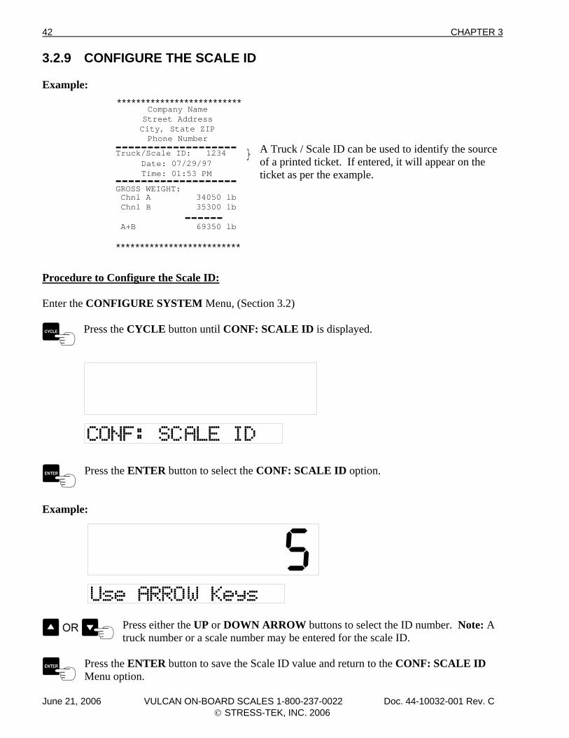
3.2.9 CONFIGURE THE SCALE ID Example:
**************************
**************************
Date: 07/29/97Time: 01:53 PM
Company NameStreet AddressCity, State ZIPPhone Number-------------------
-------------------
------GROSS WEIGHT: Chnl A 34050 lb Chnl B 35300 lb
A+B 69350 lb
Truck/Scale ID: 1234
A Truck / Scale ID can be used to identify the source of a printed ticket. If entered, it will appear on the ticket as per the example.
Procedure to Configure the Scale ID: Enter the CONFIGURE SYSTEM Menu, (Section 3.2)
Press the CYCLE button until CONF: SCALE ID is displayed.
Press the ENTER button to select the CONF: SCALE ID option.
Example:
Press either the UP or DOWN ARROW buttons to select the ID number. Note: A truck number or a scale number may be entered for the scale ID.
Press the ENTER button to save the Scale ID value and return to the CONF: SCALE ID Menu option.
June 21, 2006 VULCAN ON-BOARD SCALES 1-800-237-0022 Doc. 44-10032-001 Rev. C © STRESS-TEK, INC. 2006
CHAPTER 3 43
Press the CYCLE button to advance to the next CONFIGURE SYSTEM Menu option.
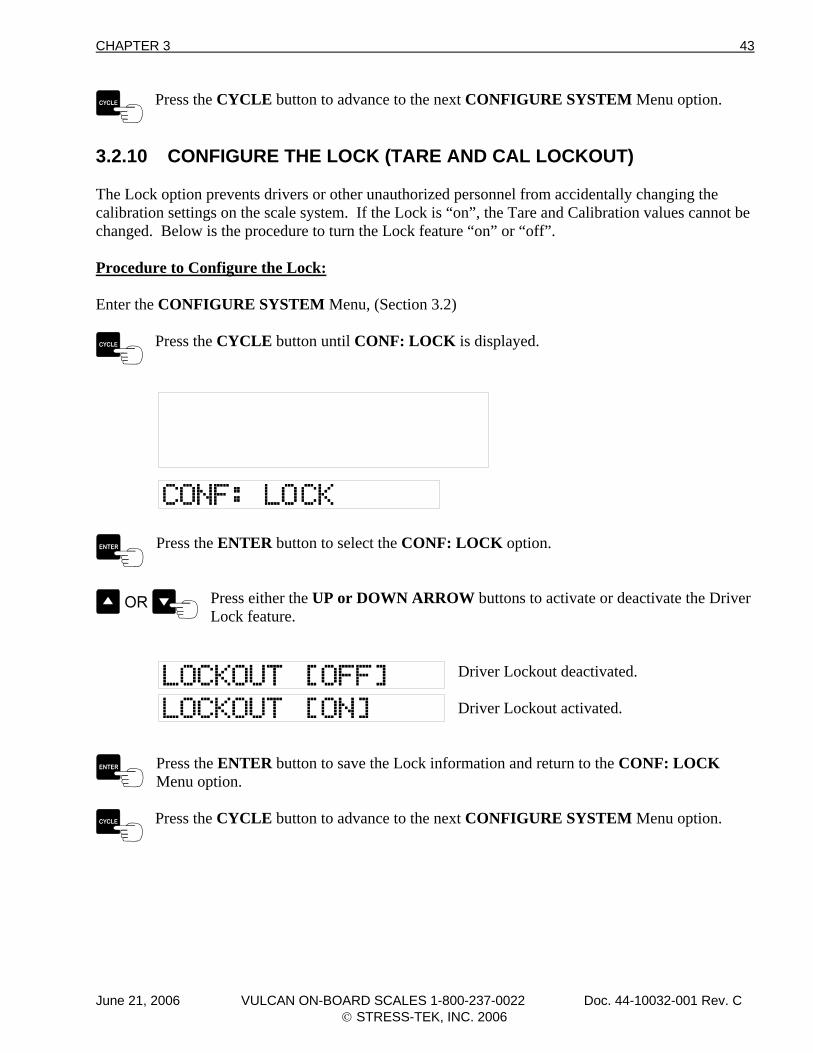
3.2.10 CONFIGURE THE LOCK (TARE AND CAL LOCKOUT) The Lock option prevents drivers or other unauthorized personnel from accidentally changing the calibration settings on the scale system. If the Lock is “on”, the Tare and Calibration values cannot be changed. Below is the procedure to turn the Lock feature “on” or “off”. Procedure to Configure the Lock: Enter the CONFIGURE SYSTEM Menu, (Section 3.2)
Press the CYCLE button until CONF: LOCK is displayed.
Press the ENTER button to select the CONF: LOCK option.
Press either the UP or DOWN ARROW buttons to activate or deactivate the Driver Lock feature.
Driver Lockout deactivated. Driver Lockout activated.
Press the ENTER button to save the Lock information and return to the CONF: LOCK Menu option.
Press the CYCLE button to advance to the next CONFIGURE SYSTEM Menu option.
June 21, 2006 VULCAN ON-BOARD SCALES 1-800-237-0022 Doc. 44-10032-001 Rev. C © STRESS-TEK, INC. 2006
44 CHAPTER 3
3.2.11 EXITING THE CONFIGURE SYSTEM MENU To Exit the Configuration System Menu:
Press the PWR / MENU button once to exit the Configure System Menu and return to the Program Main Menu. Press the PWR / MENU button twice to go directly to the normal operating mode. Note: Pressing the PWR / MENU button before pressing the ENTER button will cancel that configuration change.
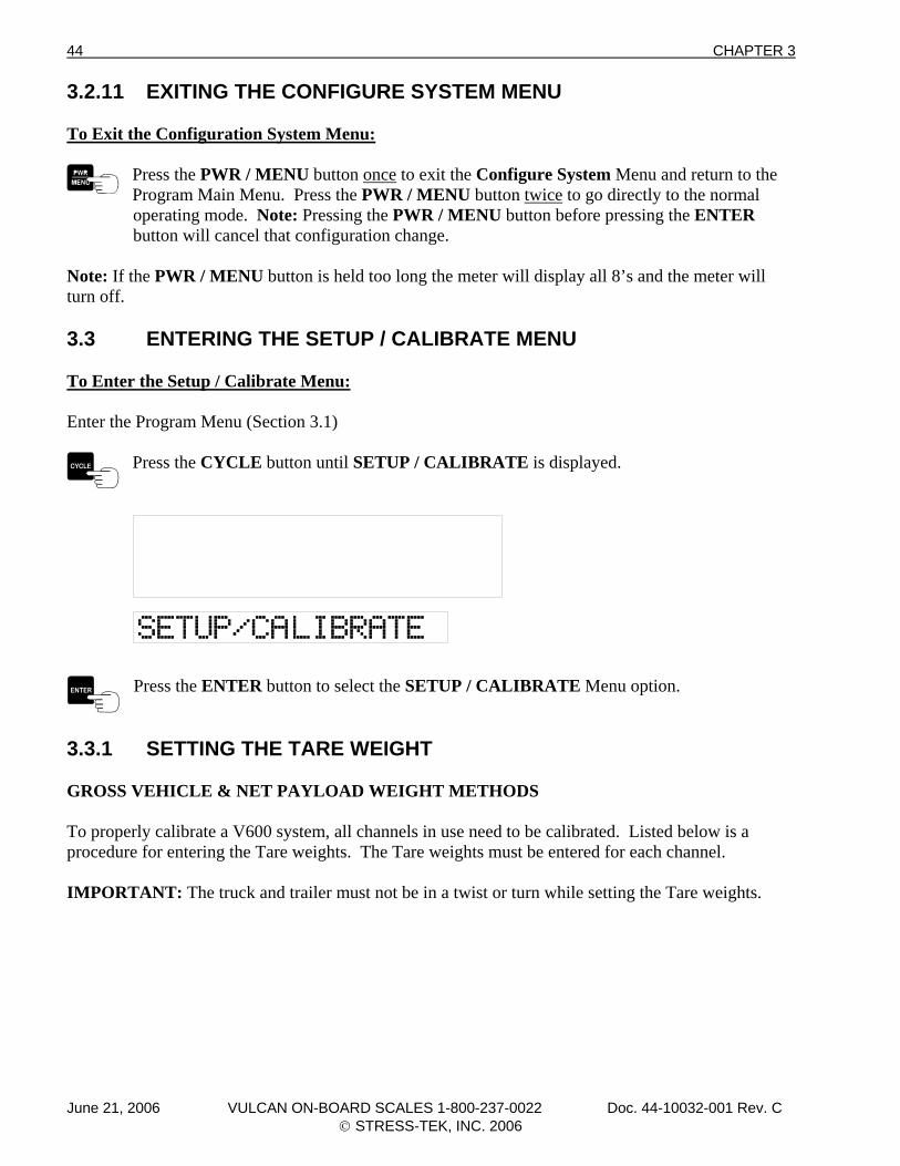
Note: If the PWR / MENU button is held too long the meter will display all 8’s and the meter will turn off. 3.3 ENTERING THE SETUP / CALIBRATE MENU To Enter the Setup / Calibrate Menu: Enter the Program Menu (Section 3.1)
Press the CYCLE button until SETUP / CALIBRATE is displayed.
Press the ENTER button to select the SETUP / CALIBRATE Menu option.
3.3.1 SETTING THE TARE WEIGHT GROSS VEHICLE & NET PAYLOAD WEIGHT METHODS To properly calibrate a V600 system, all channels in use need to be calibrated. Listed below is a procedure for entering the Tare weights. The Tare weights must be entered for each channel. IMPORTANT: The truck and trailer must not be in a twist or turn while setting the Tare weights.
June 21, 2006 VULCAN ON-BOARD SCALES 1-800-237-0022 Doc. 44-10032-001 Rev. C © STRESS-TEK, INC. 2006
CHAPTER 3 45
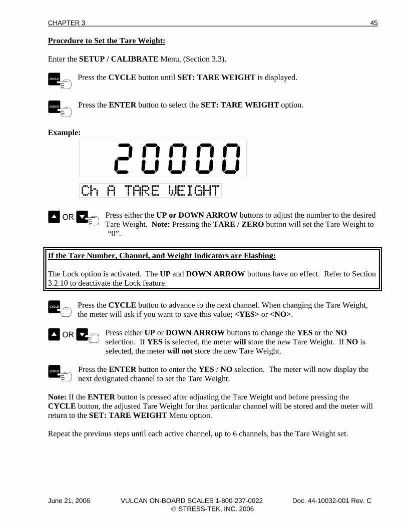
Procedure to Set the Tare Weight: Enter the SETUP / CALIBRATE Menu, (Section 3.3).
Press the CYCLE button until SET: TARE WEIGHT is displayed.
Press the ENTER button to select the SET: TARE WEIGHT option.
Example:
Press either the UP or DOWN ARROW buttons to adjust the number to the desired Tare Weight. Note: Pressing the TARE / ZERO button will set the Tare Weight to
“0”.
If the Tare Number, Channel, and Weight Indicators are Flashing: The Lock option is activated. The UP and DOWN ARROW buttons have no effect. Refer to Section 3.2.10 to deactivate the Lock feature.
Press the CYCLE button to advance to the next channel. When changing the Tare Weight, the meter will ask if you want to save this value; <YES> or <NO>.
Press either UP or DOWN ARROW buttons to change the YES or the NO selection. If YES is selected, the meter will store the new Tare Weight. If NO is
selected, the meter will not store the new Tare Weight.
Press the ENTER button to enter the YES / NO selection. The meter will now display the next designated channel to set the Tare Weight.
Note: If the ENTER button is pressed after adjusting the Tare Weight and before pressing the CYCLE button, the adjusted Tare Weight for that particular channel will be stored and the meter will return to the SET: TARE WEIGHT Menu option. Repeat the previous steps until each active channel, up to 6 channels, has the Tare Weight set.
June 21, 2006 VULCAN ON-BOARD SCALES 1-800-237-0022 Doc. 44-10032-001 Rev. C © STRESS-TEK, INC. 2006
46 CHAPTER 3
Once the last Tare Weight has been adjusted, press the ENTER button to save the new Tare Weight and return to the SET: TARE WEIGHT Menu option.
Press the CYCLE button to advance to the next SETUP / CALIBRATE Menu option.
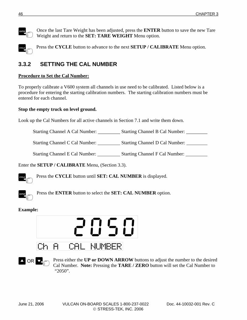
3.3.2 SETTING THE CAL NUMBER Procedure to Set the Cal Number: To properly calibrate a V600 system all channels in use need to be calibrated. Listed below is a procedure for entering the starting calibration numbers. The starting calibration numbers must be entered for each channel. Stop the empty truck on level ground. Look up the Cal Numbers for all active channels in Section 7.1 and write them down. Starting Channel A Cal Number: Starting Channel B Cal Number: Starting Channel C Cal Number: Starting Channel D Cal Number: Starting Channel E Cal Number: Starting Channel F Cal Number: Enter the SETUP / CALIBRATE Menu, (Section 3.3).
Press the CYCLE button until SET: CAL NUMBER is displayed.
Press the ENTER button to select the SET: CAL NUMBER option.
Example:
Press either the UP or DOWN ARROW buttons to adjust the number to the desired Cal Number. Note: Pressing the TARE / ZERO button will set the Cal Number to
“2050”.
June 21, 2006 VULCAN ON-BOARD SCALES 1-800-237-0022 Doc. 44-10032-001 Rev. C © STRESS-TEK, INC. 2006
CHAPTER 3 47
If the Cal Number, and Channel, Indicators are Flashing: The Lock option is activated. The UP and DOWN ARROW buttons have no effect. Refer to Section 3.2.10 to deactivate the Lock feature.
Press the CYCLE button to advance to the next channel. When changing the Cal Number, the meter will ask if you want to save this value; <YES> or <NO>.
Press either UP or DOWN ARROW buttons to change the YES or the NO selection. If YES is selected, the meter will store the new Cal Number. If NO is
selected, the meter will not store the new Cal Number.
Press the ENTER button to enter the YES or NO selection. The meter will now display the next designated channel to set the Cal Number.
Note: If the ENTER button is pressed after adjusting the Cal Number and before pressing the CYCLE button, the adjusted Cal Number for that particular channel will be stored and the meter will return to the SET: CAL NUMBER Menu option. Repeat the previous steps until each active channel, up to 6 channels, has the Cal Number set.
Once the last Cal Number has been adjusted, press the ENTER button to save the new Cal Number and return to the SET: CAL NUMBER Menu option.
Press the CYCLE button to advance to the next SETUP / CALIBRATE Menu option.
3.3.3 SETTING THE CAL WEIGHT Instead of entering a Cal Number, you may alternatively enter a Cal Weight. However, in order to use the Cal Weight option, the truck must be carrying a known weight. The meter will then use the Cal Weight and the Tare Weight to compute a Cal Number for you. To use this method of calibration, load the truck to near maximum, then drive to a certified platform scale and weigh each channel’s axle group. With the truck on the platform scale, enter the platform scale’s reading as the Cal Weight for that channel, using the procedure below. Note: The displayed Cal Weight is “live”. That is, it will change as the weight changes or the truck shifts. Each time you change the displayed weight using one of the UP or DOWN ARROW buttons, a new Cal Number is computed and then used to calculate the displayed weight.
June 21, 2006 VULCAN ON-BOARD SCALES 1-800-237-0022 Doc. 44-10032-001 Rev. C © STRESS-TEK, INC. 2006
48 CHAPTER 3
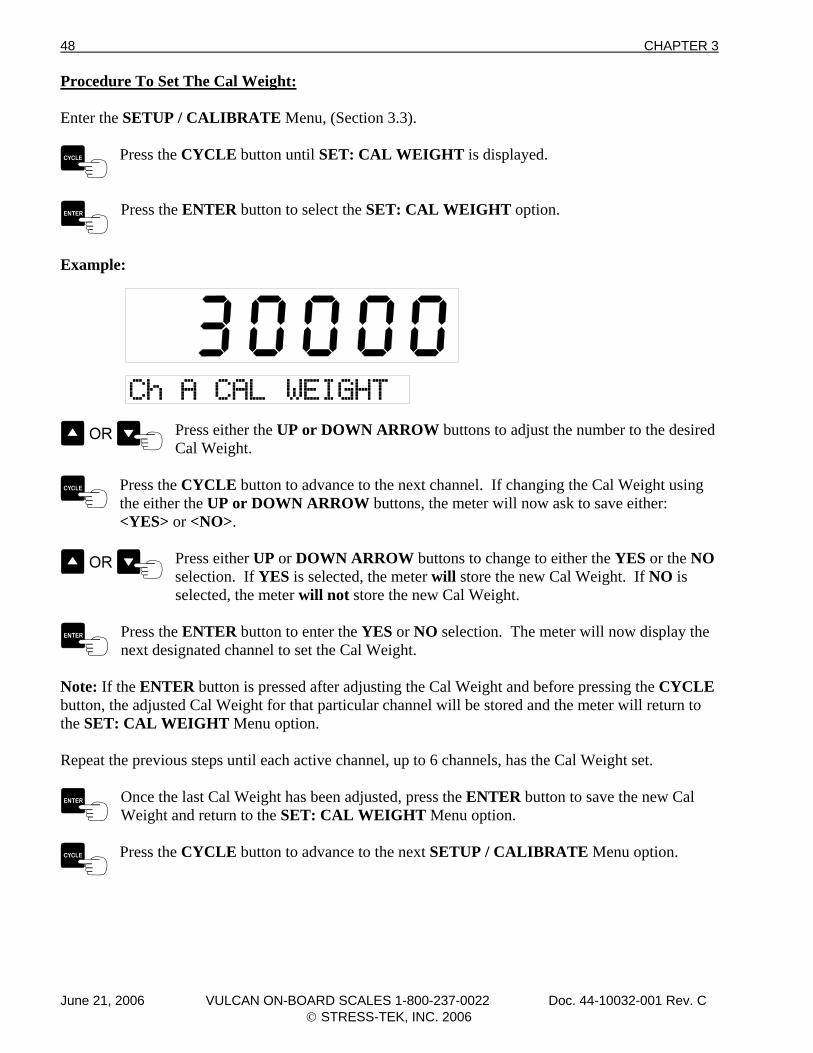
Procedure To Set The Cal Weight: Enter the SETUP / CALIBRATE Menu, (Section 3.3).
Press the CYCLE button until SET: CAL WEIGHT is displayed.
Press the ENTER button to select the SET: CAL WEIGHT option.
Example:
Press either the UP or DOWN ARROW buttons to adjust the number to the desired Cal Weight.
Press the CYCLE button to advance to the next channel. If changing the Cal Weight using the either the UP or DOWN ARROW buttons, the meter will now ask to save either:
<YES> or <NO>.
Press either UP or DOWN ARROW buttons to change to either the YES or the NO selection. If YES is selected, the meter will store the new Cal Weight. If NO is
selected, the meter will not store the new Cal Weight.
Press the ENTER button to enter the YES or NO selection. The meter will now display the next designated channel to set the Cal Weight.
Note: If the ENTER button is pressed after adjusting the Cal Weight and before pressing the CYCLE button, the adjusted Cal Weight for that particular channel will be stored and the meter will return to the SET: CAL WEIGHT Menu option. Repeat the previous steps until each active channel, up to 6 channels, has the Cal Weight set.
Once the last Cal Weight has been adjusted, press the ENTER button to save the new Cal Weight and return to the SET: CAL WEIGHT Menu option.
Press the CYCLE button to advance to the next SETUP / CALIBRATE Menu option.
June 21, 2006 VULCAN ON-BOARD SCALES 1-800-237-0022 Doc. 44-10032-001 Rev. C © STRESS-TEK, INC. 2006
CHAPTER 3 49
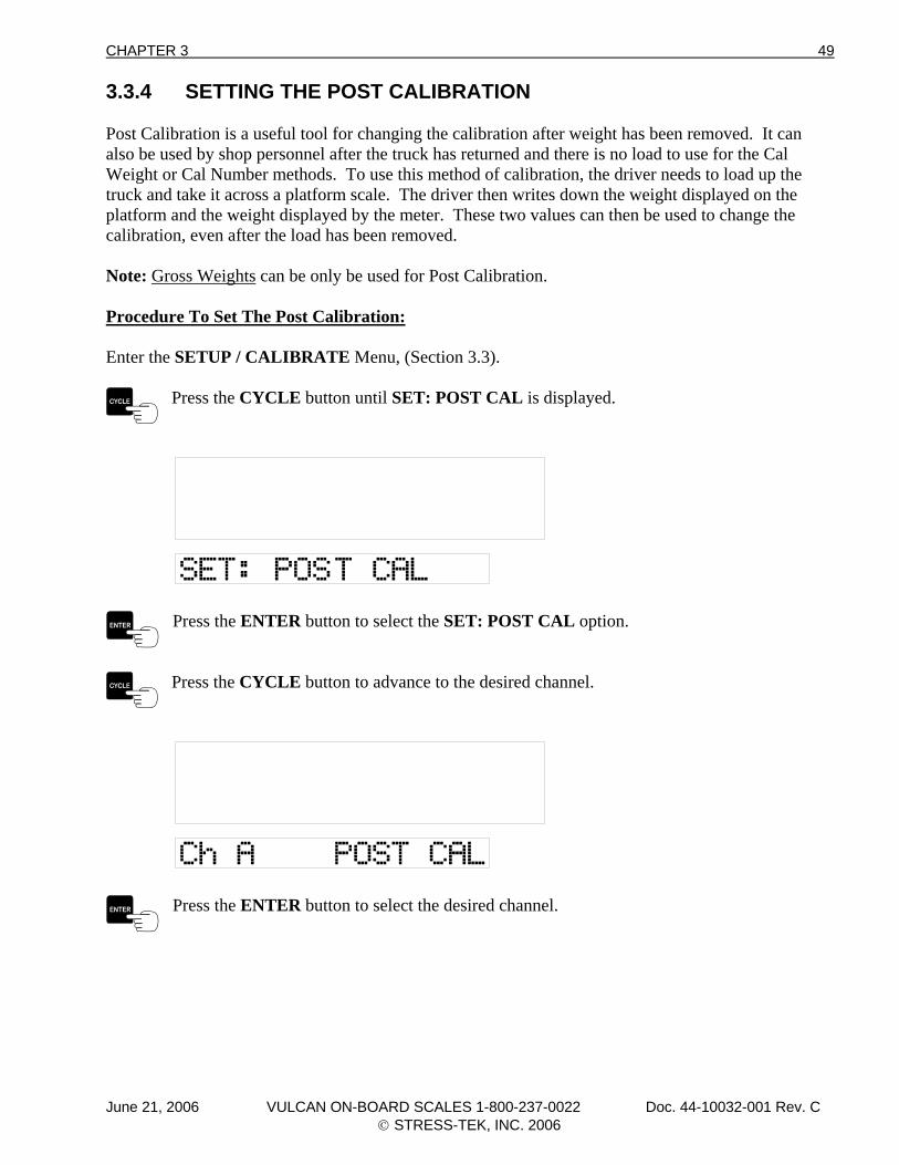
3.3.4 SETTING THE POST CALIBRATION Post Calibration is a useful tool for changing the calibration after weight has been removed. It can also be used by shop personnel after the truck has returned and there is no load to use for the Cal Weight or Cal Number methods. To use this method of calibration, the driver needs to load up the truck and take it across a platform scale. The driver then writes down the weight displayed on the platform and the weight displayed by the meter. These two values can then be used to change the calibration, even after the load has been removed. Note: Gross Weights can be only be used for Post Calibration. Procedure To Set The Post Calibration: Enter the SETUP / CALIBRATE Menu, (Section 3.3).
Press the CYCLE button until SET: POST CAL is displayed.
Press the ENTER button to select the SET: POST CAL option.
Press the CYCLE button to advance to the desired channel.
Press the ENTER button to select the desired channel.
June 21, 2006 VULCAN ON-BOARD SCALES 1-800-237-0022 Doc. 44-10032-001 Rev. C © STRESS-TEK, INC. 2006
50 CHAPTER 3
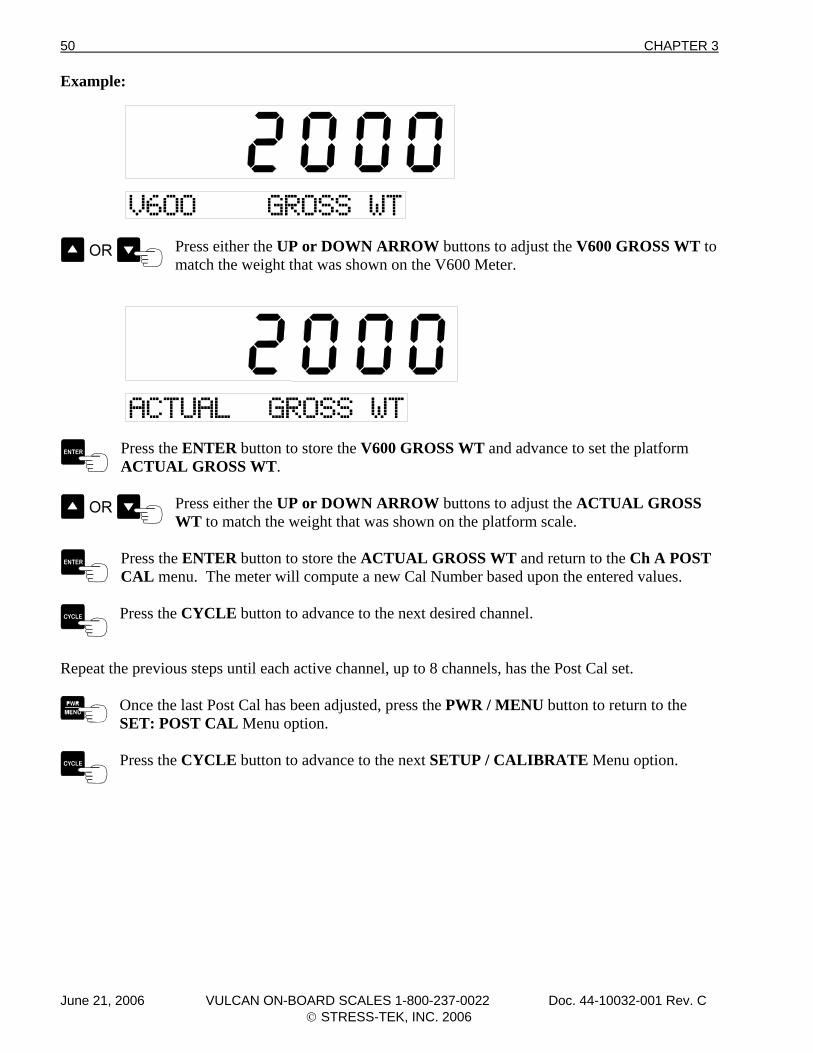
Example:
Press either the UP or DOWN ARROW buttons to adjust the V600 GROSS WT to match the weight that was shown on the V600 Meter.
Press the ENTER button to store the V600 GROSS WT and advance to set the platform ACTUAL GROSS WT.
Press either the UP or DOWN ARROW buttons to adjust the ACTUAL GROSS WT to match the weight that was shown on the platform scale.
Press the ENTER button to store the ACTUAL GROSS WT and return to the Ch A POST CAL menu. The meter will compute a new Cal Number based upon the entered values.
Press the CYCLE button to advance to the next desired channel.
Repeat the previous steps until each active channel, up to 8 channels, has the Post Cal set.
Once the last Post Cal has been adjusted, press the PWR / MENU button to return to the SET: POST CAL Menu option.
Press the CYCLE button to advance to the next SETUP / CALIBRATE Menu option.
June 21, 2006 VULCAN ON-BOARD SCALES 1-800-237-0022 Doc. 44-10032-001 Rev. C © STRESS-TEK, INC. 2006
CHAPTER 3 51
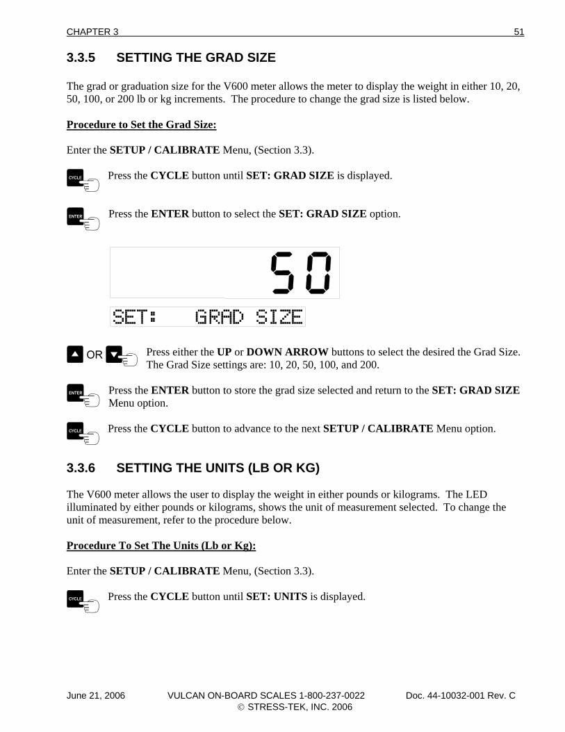
3.3.5 SETTING THE GRAD SIZE The grad or graduation size for the V600 meter allows the meter to display the weight in either 10, 20, 50, 100, or 200 lb or kg increments. The procedure to change the grad size is listed below. Procedure to Set the Grad Size: Enter the SETUP / CALIBRATE Menu, (Section 3.3).
Press the CYCLE button until SET: GRAD SIZE is displayed.
Press the ENTER button to select the SET: GRAD SIZE option.
Press either the UP or DOWN ARROW buttons to select the desired the Grad Size. The Grad Size settings are: 10, 20, 50, 100, and 200.
Press the ENTER button to store the grad size selected and return to the SET: GRAD SIZE Menu option.
Press the CYCLE button to advance to the next SETUP / CALIBRATE Menu option.
3.3.6 SETTING THE UNITS (LB OR KG) The V600 meter allows the user to display the weight in either pounds or kilograms. The LED illuminated by either pounds or kilograms, shows the unit of measurement selected. To change the unit of measurement, refer to the procedure below. Procedure To Set The Units (Lb or Kg): Enter the SETUP / CALIBRATE Menu, (Section 3.3).
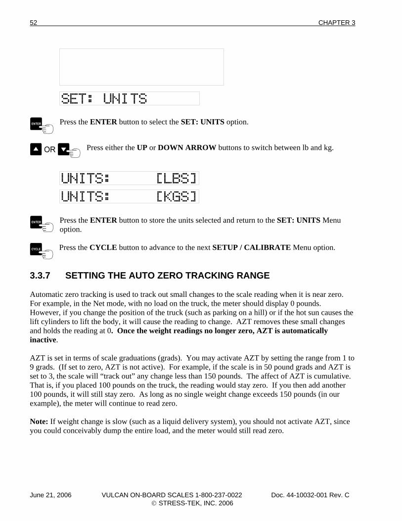
Press the CYCLE button until SET: UNITS is displayed.
June 21, 2006 VULCAN ON-BOARD SCALES 1-800-237-0022 Doc. 44-10032-001 Rev. C © STRESS-TEK, INC. 2006
52 CHAPTER 3
Press the ENTER button to select the SET: UNITS option.
Press either the UP or DOWN ARROW buttons to switch between lb and kg.
Press the ENTER button to store the units selected and return to the SET: UNITS Menu option.
Press the CYCLE button to advance to the next SETUP / CALIBRATE Menu option.
3.3.7 SETTING THE AUTO ZERO TRACKING RANGE Automatic zero tracking is used to track out small changes to the scale reading when it is near zero. For example, in the Net mode, with no load on the truck, the meter should display 0 pounds. However, if you change the position of the truck (such as parking on a hill) or if the hot sun causes the lift cylinders to lift the body, it will cause the reading to change. AZT removes these small changes and holds the reading at 0. Once the weight readings no longer zero, AZT is automatically inactive. AZT is set in terms of scale graduations (grads). You may activate AZT by setting the range from 1 to 9 grads. (If set to zero, AZT is not active). For example, if the scale is in 50 pound grads and AZT is set to 3, the scale will “track out” any change less than 150 pounds. The affect of AZT is cumulative. That is, if you placed 100 pounds on the truck, the reading would stay zero. If you then add another 100 pounds, it will still stay zero. As long as no single weight change exceeds 150 pounds (in our example), the meter will continue to read zero. Note: If weight change is slow (such as a liquid delivery system), you should not activate AZT, since you could conceivably dump the entire load, and the meter would still read zero.
June 21, 2006 VULCAN ON-BOARD SCALES 1-800-237-0022 Doc. 44-10032-001 Rev. C © STRESS-TEK, INC. 2006
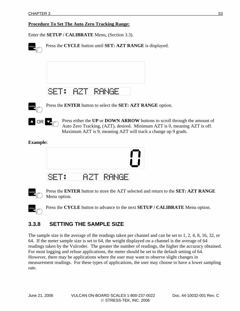
CHAPTER 3 53
Procedure To Set The Auto Zero Tracking Range: Enter the SETUP / CALIBRATE Menu, (Section 3.3).
Press the CYCLE button until SET: AZT RANGE is displayed.
Press the ENTER button to select the SET: AZT RANGE option.
Press either the UP or DOWN ARROW buttons to scroll through the amount of Auto Zero Tracking, (AZT), desired. Minimum AZT is 0, meaning AZT is off.
Maximum AZT is 9, meaning AZT will track a change up 9 grads.
Example:
Press the ENTER button to store the AZT selected and return to the SET: AZT RANGE Menu option.
Press the CYCLE button to advance to the next SETUP / CALIBRATE Menu option.
3.3.8 SETTING THE SAMPLE SIZE The sample size is the average of the readings taken per channel and can be set to 1, 2, 4, 8, 16, 32, or 64. If the meter sample size is set to 64, the weight displayed on a channel is the average of 64 readings taken by the Vulcoder. The greater the number of readings, the higher the accuracy obtained. For most logging and refuse applications, the meter should be set to the default setting of 64. However, there may be applications where the user may want to observe slight changes in measurement readings. For these types of applications, the user may choose to have a lower sampling rate.
June 21, 2006 VULCAN ON-BOARD SCALES 1-800-237-0022 Doc. 44-10032-001 Rev. C © STRESS-TEK, INC. 2006
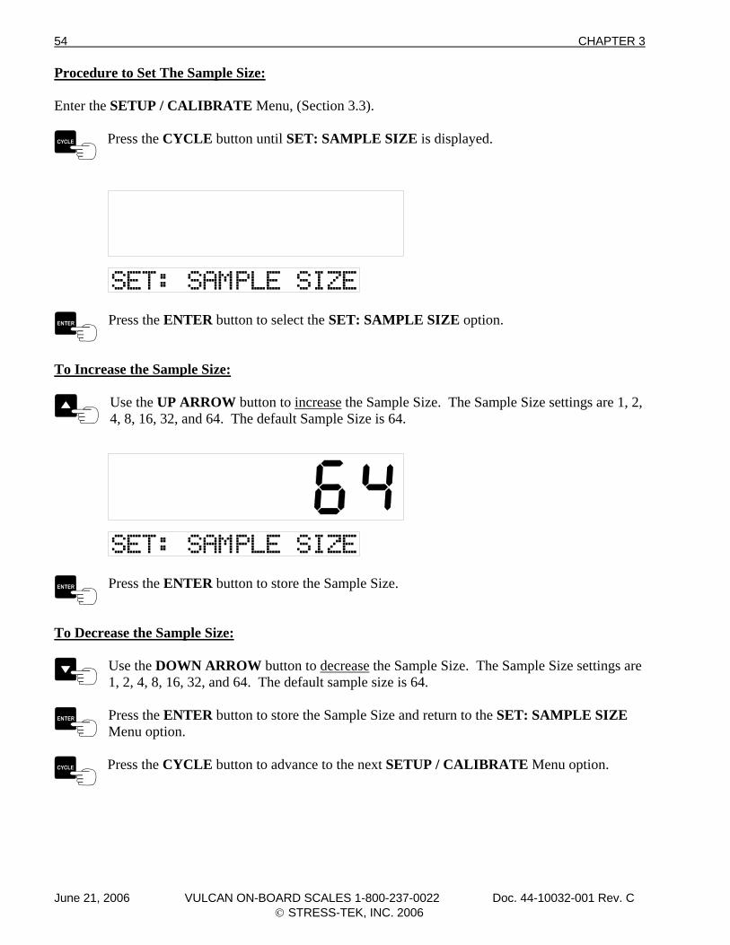
54 CHAPTER 3
Procedure to Set The Sample Size: Enter the SETUP / CALIBRATE Menu, (Section 3.3).
Press the CYCLE button until SET: SAMPLE SIZE is displayed.
Press the ENTER button to select the SET: SAMPLE SIZE option.
To Increase the Sample Size:
Use the UP ARROW button to increase the Sample Size. The Sample Size settings are 1, 2, 4, 8, 16, 32, and 64. The default Sample Size is 64.
Press the ENTER button to store the Sample Size.
To Decrease the Sample Size:
Use the DOWN ARROW button to decrease the Sample Size. The Sample Size settings are 1, 2, 4, 8, 16, 32, and 64. The default sample size is 64.
Press the ENTER button to store the Sample Size and return to the SET: SAMPLE SIZE Menu option.
Press the CYCLE button to advance to the next SETUP / CALIBRATE Menu option.
June 21, 2006 VULCAN ON-BOARD SCALES 1-800-237-0022 Doc. 44-10032-001 Rev. C © STRESS-TEK, INC. 2006
CHAPTER 3 55
3.3.9 EXITING THE SETUP / CALIBRATE MENU To Exit the Setup / Calibrate Menu:
Press the PWR / MENU button once to exit the Setup / Calibrate Menu and return to the Program Main Menu. Press the PWR / MENU button twice to go directly to the normal operating mode. Note: Pressing the PWR / MENU button before pressing the ENTER button will cancel that configuration change.
Note: If the PWR / MENU button is held too long the meter will display all 8’s and the meter will turn off. 3.4 SEQUENCING CHANNELS The V600 electronics makes it possible for a truck to haul various types of Vulcan VSL equipped trailers with “plug in and go” ease. To do this, the VSL Vulcoders need to be assigned their position (Channel A, B, C, or D) in the scale system. Once the Vulcoder has been assigned its position, it will remember it and the process of sequencing does not need to be repeated, unless the position of the Vulcoder changes. Sequencing is the process in which the meter determines the order of each VSL Vulcoder or groups of load cells. For example, on a long logger, the meter reads the Front VSL Vulcoder and assigns it as Channel A, and then reads the next VSL Vulcoder as a Rear and assigns this VSL Vulcoder as Channel B. For example, if “<FrFr>” is shown on the display, this would indicate that four Vulcoders were detected. “F” indicates a front VSL Vulcoder and “r” indicates a rear VSL Vulcoder. The associated channels will also be displayed. Note: On new installations, the system will make an attempt to automatically sequence the Vulcoders. If the attempt is not successful (i.e. more than one Front or Rear Vulcoder is hooked up when the meter is turned on) an Error code will be displayed (i.e. Err 03, Err 07, Err 08, or Err 09). If this happens then the system will have to be Manually Sequenced.
June 21, 2006 VULCAN ON-BOARD SCALES 1-800-237-0022 Doc. 44-10032-001 Rev. C © STRESS-TEK, INC. 2006
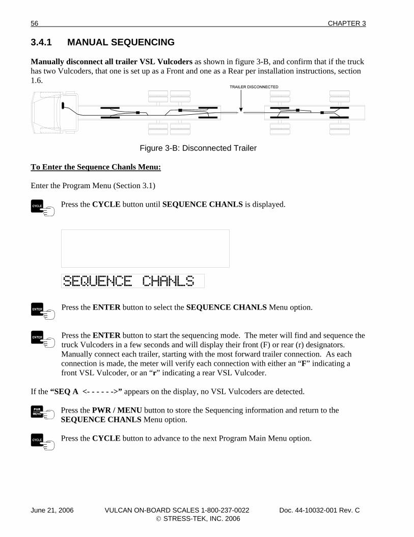
56 CHAPTER 3
3.4.1 MANUAL SEQUENCING Manually disconnect all trailer VSL Vulcoders as shown in figure 3-B, and confirm that if the truck has two Vulcoders, that one is set up as a Front and one as a Rear per installation instructions, section 1.6.
Figure 3-B: Disconnected Trailer To Enter the Sequence Chanls Menu: Enter the Program Menu (Section 3.1)
Press the CYCLE button until SEQUENCE CHANLS is displayed.
Press the ENTER button to select the SEQUENCE CHANLS Menu option.
Press the ENTER button to start the sequencing mode. The meter will find and sequence the truck Vulcoders in a few seconds and will display their front (F) or rear (r) designators.
Manually connect each trailer, starting with the most forward trailer connection. As each connection is made, the meter will verify each connection with either an “F” indicating a front VSL Vulcoder, or an “r” indicating a rear VSL Vulcoder.
If the “SEQ A <- - - - - ->” appears on the display, no VSL Vulcoders are detected.
Press the PWR / MENU button to store the Sequencing information and return to the SEQUENCE CHANLS Menu option.
Press the CYCLE button to advance to the next Program Main Menu option.
June 21, 2006 VULCAN ON-BOARD SCALES 1-800-237-0022 Doc. 44-10032-001 Rev. C © STRESS-TEK, INC. 2006
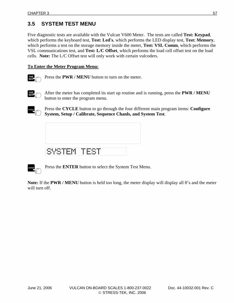
CHAPTER 3 57
3.5 SYSTEM TEST MENU Five diagnostic tests are available with the Vulcan V600 Meter. The tests are called Test: Keypad, which performs the keyboard test, Test: Led's, which performs the LED display test, Test: Memory, which performs a test on the storage memory inside the meter, Test: VSL Comm, which performs the VSL communications test, and Test: L/C Offset, which performs the load cell offset test on the load cells. Note: The L/C Offset test will only work with certain vulcoders. To Enter the Meter Program Menu:
Press the PWR / MENU button to turn on the meter.
After the meter has completed its start up routine and is running, press the PWR / MENU button to enter the program menu.
Press the CYCLE button to go through the four different main program items: Configure System, Setup / Calibrate, Sequence Chanls, and System Test.
Press the ENTER button to select the System Test Menu.
Note: If the PWR / MENU button is held too long, the meter display will display all 8’s and the meter will turn off.
June 21, 2006 VULCAN ON-BOARD SCALES 1-800-237-0022 Doc. 44-10032-001 Rev. C © STRESS-TEK, INC. 2006
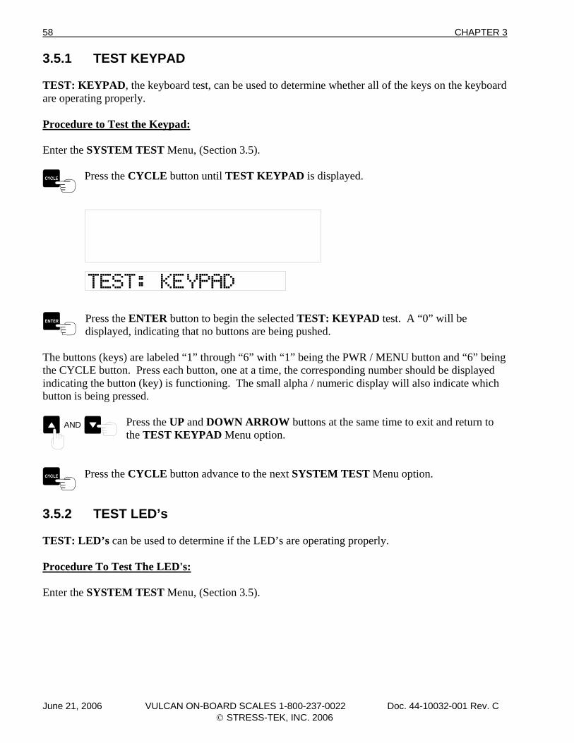
58 CHAPTER 3
3.5.1 TEST KEYPAD TEST: KEYPAD, the keyboard test, can be used to determine whether all of the keys on the keyboard are operating properly. Procedure to Test the Keypad: Enter the SYSTEM TEST Menu, (Section 3.5).
Press the CYCLE button until TEST KEYPAD is displayed.
Press the ENTER button to begin the selected TEST: KEYPAD test. A “0” will be displayed, indicating that no buttons are being pushed.
The buttons (keys) are labeled “1” through “6” with “1” being the PWR / MENU button and “6” being the CYCLE button. Press each button, one at a time, the corresponding number should be displayed indicating the button (key) is functioning. The small alpha / numeric display will also indicate which button is being pressed.
Press the UP and DOWN ARROW buttons at the same time to exit and return to the TEST KEYPAD Menu option.
AND
Press the CYCLE button advance to the next SYSTEM TEST Menu option.
3.5.2 TEST LED’s TEST: LED’s can be used to determine if the LED’s are operating properly. Procedure To Test The LED's: Enter the SYSTEM TEST Menu, (Section 3.5).
June 21, 2006 VULCAN ON-BOARD SCALES 1-800-237-0022 Doc. 44-10032-001 Rev. C © STRESS-TEK, INC. 2006
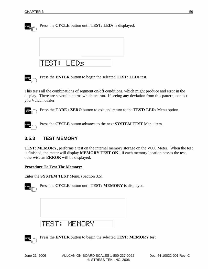
CHAPTER 3 59
Press the CYCLE button until TEST: LEDs is displayed.
Press the ENTER button to begin the selected TEST: LEDs test.
This tests all the combinations of segment on/off conditions, which might produce and error in the display. There are several patterns which are run. If seeing any deviation from this pattern, contact you Vulcan dealer.
Press the TARE / ZERO button to exit and return to the TEST: LEDs Menu option.
Press the CYCLE button advance to the next SYSTEM TEST Menu item.
3.5.3 TEST MEMORY TEST: MEMORY, performs a test on the internal memory storage on the V600 Meter. When the test is finished, the meter will display MEMORY TEST OK!, if each memory location passes the test, otherwise an ERROR will be displayed. Procedure To Test The Memory: Enter the SYSTEM TEST Menu, (Section 3.5).
Press the CYCLE button until TEST: MEMORY is displayed.
Press the ENTER button to begin the selected TEST: MEMORY test.
June 21, 2006 VULCAN ON-BOARD SCALES 1-800-237-0022 Doc. 44-10032-001 Rev. C © STRESS-TEK, INC. 2006
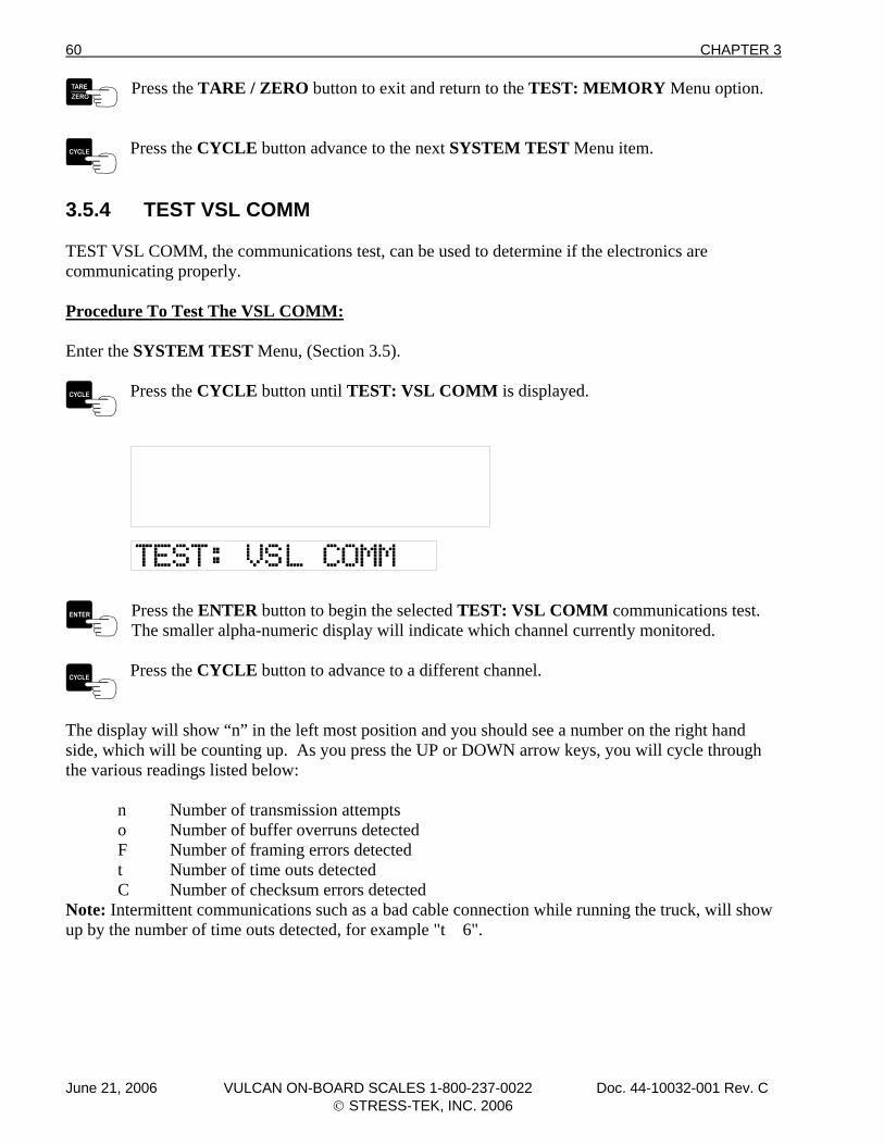
60 CHAPTER 3
Press the TARE / ZERO button to exit and return to the TEST: MEMORY Menu option.
Press the CYCLE button advance to the next SYSTEM TEST Menu item.
3.5.4 TEST VSL COMM TEST VSL COMM, the communications test, can be used to determine if the electronics are communicating properly. Procedure To Test The VSL COMM: Enter the SYSTEM TEST Menu, (Section 3.5).
Press the CYCLE button until TEST: VSL COMM is displayed.
Press the ENTER button to begin the selected TEST: VSL COMM communications test. The smaller alpha-numeric display will indicate which channel currently monitored.
Press the CYCLE button to advance to a different channel.
The display will show “n” in the left most position and you should see a number on the right hand side, which will be counting up. As you press the UP or DOWN arrow keys, you will cycle through the various readings listed below: n Number of transmission attempts
o Number of buffer overruns detected F Number of framing errors detected t Number of time outs detected C Number of checksum errors detected Note: Intermittent communications such as a bad cable connection while running the truck, will show up by the number of time outs detected, for example "t 6".
June 21, 2006 VULCAN ON-BOARD SCALES 1-800-237-0022 Doc. 44-10032-001 Rev. C © STRESS-TEK, INC. 2006
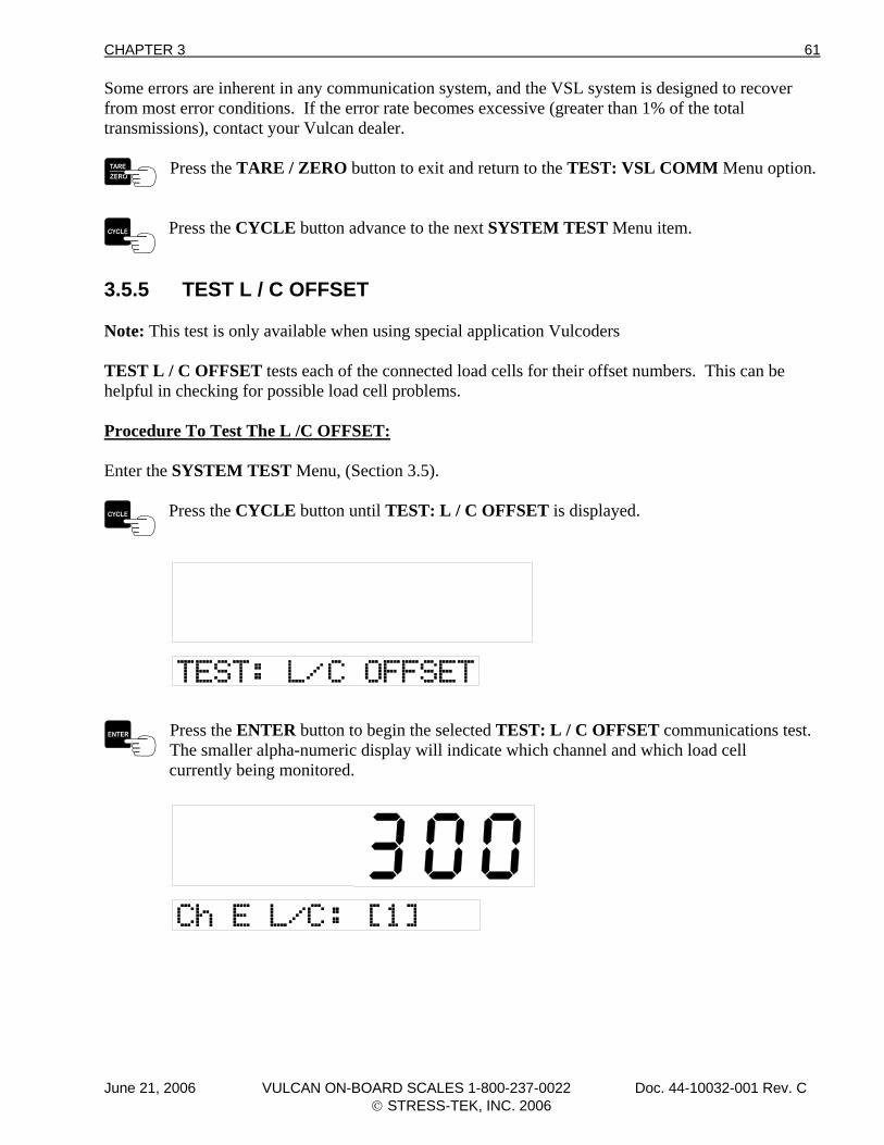
CHAPTER 3 61
Some errors are inherent in any communication system, and the VSL system is designed to recover from most error conditions. If the error rate becomes excessive (greater than 1% of the total transmissions), contact your Vulcan dealer.
Press the TARE / ZERO button to exit and return to the TEST: VSL COMM Menu option.
Press the CYCLE button advance to the next SYSTEM TEST Menu item.
3.5.5 TEST L / C OFFSET Note: This test is only available when using special application Vulcoders TEST L / C OFFSET tests each of the connected load cells for their offset numbers. This can be helpful in checking for possible load cell problems. Procedure To Test The L /C OFFSET: Enter the SYSTEM TEST Menu, (Section 3.5).
Press the CYCLE button until TEST: L / C OFFSET is displayed.
Press the ENTER button to begin the selected TEST: L / C OFFSET communications test. The smaller alpha-numeric display will indicate which channel and which load cell
currently being monitored.
June 21, 2006 VULCAN ON-BOARD SCALES 1-800-237-0022 Doc. 44-10032-001 Rev. C © STRESS-TEK, INC. 2006
62 CHAPTER 3
Press either the UP or DOWN ARROW buttons to display the next load cell. The smaller alpha-numeric display will indicate which channel and display the next
load cell being monitored.
Repeat the above steps until all of the channel and load cells have been tested. Note: Standard Vulcoders do not have this capability, therefore the meter will display an ERROR on the large display and the smaller alpha numeric display will display which channel is being monitored and see manual. For example, Ch A SEE MANUAL will be displayed if Channel A Vulcoder is of the older design.
Press the CYCLE button to advance to a different channel.
3.6 EXITING THE PROGRAM MENU To Exit the Meter Program Menu:
Press the PWR / MENU button once to exit from the Program Main Menu at any time to return to the normal operating mode.
Note: If the PWR / MENU button is held too long the meter will display all 8’s and the meter will turn off.
June 21, 2006 VULCAN ON-BOARD SCALES 1-800-237-0022 Doc. 44-10032-001 Rev. C © STRESS-TEK, INC. 2006
CHAPTER 4 63
C H A P T E R 4 . 0 V600 CALIBRATION Calibration is fine tuning a system to maximum accuracy in reference to a specific certified platform scale. It is important to calibrate the scales for high accuracy to achieve the maximum hauling payload. Calibration consists of setting the appropriate Tare weight and Calibration number for each channel. It is important that conditions remain as constant as possible throughout the calibration process. Inaccuracies may result from differences in fuel load, ice or mud build-up, number of people in the vehicle, etc. It may take 2 or 3 attempts at calibration to achieve the optimum setting. Calibration should be done anytime a system is installed, if there are continuous questionable readings, or if meter readings repeatably do not closely match the certified platform scale weights. 4.1 WEIGHT MEASURING METHODS The Vulcan Scale System can be used to measure weight by two different methods. These methods are Gross Vehicle weight and Net Payload weight. In addition to these methods, Vulcan Scales can be used to determine Axle Weight on certain on-board scale configurations. Important Notice for Front Loader Refuse Truck Operators using load cells to support the body: To avoid weight measurement errors, the forks must be in the down position and the body lift cylinder pressure must be relieved at the time of measuring for all methods. The pressure relief valve should be engaged during weight measurements. If the truck is not equipped with a pressure relief valve, relieve the pressure manually. In addition, all packing should be done after the weight is recorded. AXLE WEIGHT Vulcan Scales can be used to reduce overweight fines by measuring a vehicle’s axle weight. For some vehicle configurations, such as many logging trucks and trailers, the channel weights will be the axle group weight. For other configurations, the channel weight may not be the actual axle group weights because some of the load is being shared by other axles. For short log and refuse trucks, the scales can indicate a weight on an axle group that should not be exceeded in order to keep the truck legal. Load the truck close to the legal maximum according to a certified platform scale. The number displayed on the channel of the meter corresponding to the axle group represents an approximate rear axle group weight and may be used as a reference weight to avoid exceeding the legal limit. This reference weight may be different from the weight shown on the certified platform scale display. Note: Channel “A” does not represent the steering axle weight when fully loaded.
June 21, 2006 VULCAN ON-BOARD SCALES 1-800-237-0022 Doc. 44-10032-001 Rev. C © STRESS-TEK, INC. 2006
64 CHAPTER 4
4.1.1 GROSS VEHICLE WEIGHT Gross Vehicle Weight: Entire truck weight including fuel, equipment, personnel, and payload. In order to use the Gross Vehicle weight method, the Tare weight for each channel must be entered. The Tare weight is the weight of the empty truck with fuel, equipment, personnel and no payload. For example, if the Tare weight is 30,000 lb, the meter will display this weight before any payload has been loaded. As the payload increases, the weight displayed on the meter will also increase. For a 2-channel system (A and B) the total Gross Vehicle weight is displayed on Channel A+B. For a 4-channel system, the total Gross Vehicle weight is displayed as Channel A+B+C+D. 4.1.2 NET PAYLOAD WEIGHT Net Payload weight: Weight of the truck’s payload only. By using the Net Payload weight method, payload pickups are measured cumulatively. Net Payload weight can be measured when the truck’s Tare weight is set to zero for each channel. The weight displayed at all times is the Net Payload weight. 4.2 PROCEDURE FOR ENTERING TARE WEIGHTS GROSS VEHICLE & NET PAYLOAD WEIGHT METHODS To properly calibrate a V600 system, all channels in use need to be calibrated. Listed below is a procedure for entering the Tare weights. The Tare weights must be entered for each channel. IMPORTANT: The truck and trailer must not be in a twist or turn while entering the Tare weights. 4.2.1 Entering Tare Weight For A Typical 2 - Channel, Truck & Trailer System Weigh the entire empty truck with full fuel tanks and driver (both front and rear axles) using a certified platform scale. This is the truck’s Tare Weight. Enter this number in the space provided. For the Net Payload Weight Method the Tare weight must be set to zero. Note: If your truck will be hauling different trailers, weigh the entire empty truck with the trailer disconnected, and with full fuel tanks and driver (both front and rear axles) using a certified platform scale. Tare weight of entire empty truck: Weigh the entire empty trailer(s) (all axles). This is the trailer’s Tare weight. Enter this number in the space provided. Tare weight of entire empty trailer: Stop the empty truck and trailer on level ground.
June 21, 2006 VULCAN ON-BOARD SCALES 1-800-237-0022 Doc. 44-10032-001 Rev. C © STRESS-TEK, INC. 2006
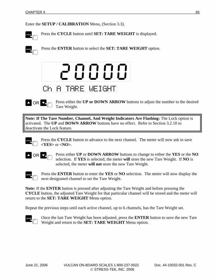
CHAPTER 4 65
Enter the SETUP / CALIBRATION Menu, (Section 3.3).
Press the CYCLE button until SET: TARE WEIGHT is displayed.
Press the ENTER button to select the SET: TARE WEIGHT option.
Press either the UP or DOWN ARROW buttons to adjust the number to the desired Tare Weight.
Note: If The Tare Number, Channel, And Weight Indicators Are Flashing: The Lock option is activated. The UP and DOWN ARROW buttons have no effect. Refer to Section 3.2.10 to deactivate the Lock feature.
Press the CYCLE button to advance to the next channel. The meter will now ask to save <YES> or <NO>.
Press either UP or DOWN ARROW buttons to change to either the YES or the NO selection. If YES is selected, the meter will store the new Tare Weight. If NO is
selected, the meter will not store the new Tare Weight.
Press the ENTER button to enter the YES or NO selection. The meter will now display the next designated channel to set the Tare Weight.
Note: If the ENTER button is pressed after adjusting the Tare Weight and before pressing the CYCLE button, the adjusted Tare Weight for that particular channel will be stored and the meter will return to the SET: TARE WEIGHT Menu option. Repeat the previous steps until each active channel, up to 6 channels, has the Tare Weight set.
Once the last Tare Weight has been adjusted, press the ENTER button to save the new Tare Weight and return to the SET: TARE WEIGHT Menu option.
June 21, 2006 VULCAN ON-BOARD SCALES 1-800-237-0022 Doc. 44-10032-001 Rev. C © STRESS-TEK, INC. 2006
66 CHAPTER 4
To Exit The SET: TARE WEIGHT Menu:
Press the PWR / MENU button once to exit the Setup / Calibrate Menu and return to the Program Main Menu. Press the PWR / MENU button twice to go directly to the normal operating mode. Note: Pressing the PWR / MENU button before pressing the ENTER button will cancel that configuration change.
Note: If the PWR / MENU button is held too long the meter will display all 8’s and the meter will turn off. 4.2.2 Entering Tare Weight For A Typical Short Logger System Weigh the entire empty truck with full fuel tanks and driver (both front and rear axles) using a certified platform scale. This is the truck’s Tare weight. Enter this number in the space provided. For the Net Payload weight method the Tare weight must be set to zero. Tare weight of entire empty truck: (Ch A) Divide the empty truck weight by 2 and enter in the space provided. Tare Weight of entire empty truck divided by 2: (Ch B) Weigh the front axle group of the empty trailer. Tare Weight of front axle group of the empty trailer: (Ch C) Weigh the rear axle group of the empty trailer. Tare Weight of rear axle group of the empty trailer: (Ch D) Procedure To Enter Tare Weights For A Typical Short Logger System: Stop the empty truck and trailer on level ground. Enter the SETUP / CALIBRATE Menu, (Section 3.3).
Press the CYCLE button until SET: TARE WEIGHT is displayed.
Press the ENTER button to select the SET: TARE WEIGHT option.
June 21, 2006 VULCAN ON-BOARD SCALES 1-800-237-0022 Doc. 44-10032-001 Rev. C © STRESS-TEK, INC. 2006
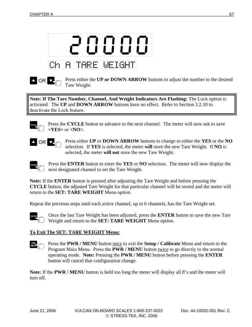
CHAPTER 4 67
Press either the UP or DOWN ARROW buttons to adjust the number to the desired Tare Weight.
Note: If The Tare Number, Channel, And Weight Indicators Are Flashing: The Lock option is activated. The UP and DOWN ARROW buttons have no effect. Refer to Section 3.2.10 to deactivate the Lock feature.
Press the CYCLE button to advance to the next channel. The meter will now ask to save <YES> or <NO>.
Press either UP or DOWN ARROW buttons to change to either the YES or the NO selection. If YES is selected, the meter will store the new Tare Weight. If NO is
selected, the meter will not store the new Tare Weight.
Press the ENTER button to enter the YES or NO selection. The meter will now display the next designated channel to set the Tare Weight.
Note: If the ENTER button is pressed after adjusting the Tare Weight and before pressing the CYCLE button, the adjusted Tare Weight for that particular channel will be stored and the meter will return to the SET: TARE WEIGHT Menu option. Repeat the previous steps until each active channel, up to 6 channels, has the Tare Weight set.
Once the last Tare Weight has been adjusted, press the ENTER button to save the new Tare Weight and return to the SET: TARE WEIGHT Menu option.
To Exit The SET: TARE WEIGHT Menu:
Press the PWR / MENU button once to exit the Setup / Calibrate Menu and return to the Program Main Menu. Press the PWR / MENU button twice to go directly to the normal operating mode. Note: Pressing the PWR / MENU button before pressing the ENTER button will cancel that configuration change.
Note: If the PWR / MENU button is held too long the meter will display all 8’s and the meter will turn off.
June 21, 2006 VULCAN ON-BOARD SCALES 1-800-237-0022 Doc. 44-10032-001 Rev. C © STRESS-TEK, INC. 2006
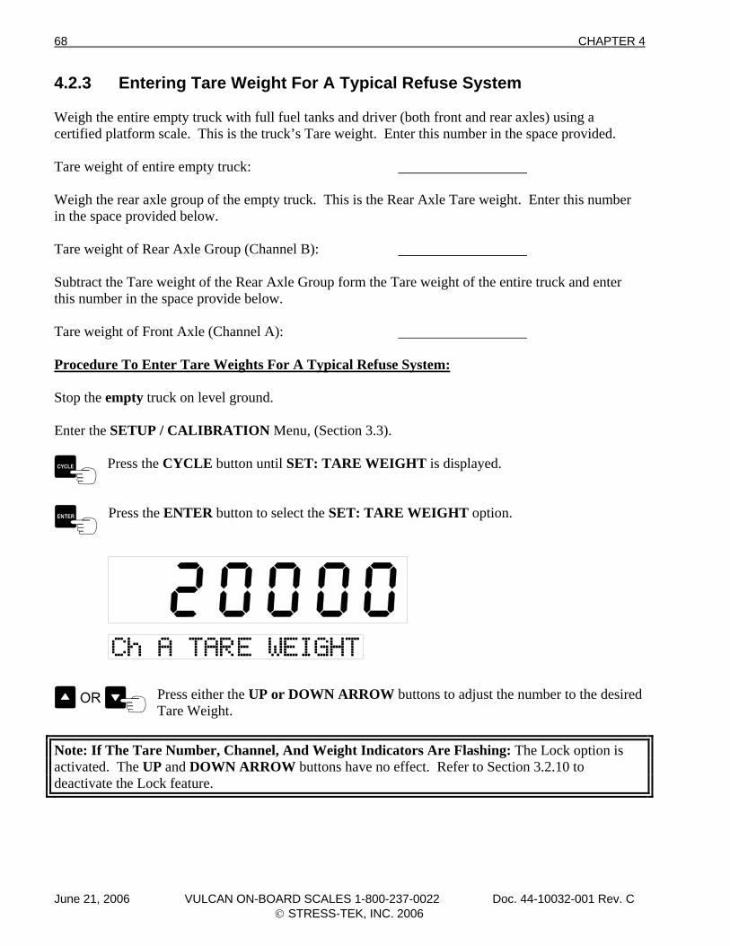
68 CHAPTER 4
4.2.3 Entering Tare Weight For A Typical Refuse System Weigh the entire empty truck with full fuel tanks and driver (both front and rear axles) using a certified platform scale. This is the truck’s Tare weight. Enter this number in the space provided. Tare weight of entire empty truck: Weigh the rear axle group of the empty truck. This is the Rear Axle Tare weight. Enter this number in the space provided below. Tare weight of Rear Axle Group (Channel B): Subtract the Tare weight of the Rear Axle Group form the Tare weight of the entire truck and enter this number in the space provide below. Tare weight of Front Axle (Channel A): Procedure To Enter Tare Weights For A Typical Refuse System: Stop the empty truck on level ground. Enter the SETUP / CALIBRATION Menu, (Section 3.3).
Press the CYCLE button until SET: TARE WEIGHT is displayed.
Press the ENTER button to select the SET: TARE WEIGHT option.
Press either the UP or DOWN ARROW buttons to adjust the number to the desired Tare Weight.
Note: If The Tare Number, Channel, And Weight Indicators Are Flashing: The Lock option is activated. The UP and DOWN ARROW buttons have no effect. Refer to Section 3.2.10 to deactivate the Lock feature.
June 21, 2006 VULCAN ON-BOARD SCALES 1-800-237-0022 Doc. 44-10032-001 Rev. C © STRESS-TEK, INC. 2006
CHAPTER 4 69
Press the CYCLE button to advance to the next channel. If changing the Tare Number using the either the UP or DOWN ARROW buttons, the meter will now ask to save either:
<YES> or <NO>.
Press either UP or DOWN ARROW buttons to change to either the YES or the NO selection. If YES is selected, the meter will store the new Tare Weight. If NO is
selected, the meter will not store the new Tare Weight.
Press the ENTER button to enter the YES or NO selection. The meter will now display the next designated channel to set the Tare Weight.
Note: If the ENTER button is pressed after adjusting the Tare Weight and before pressing the CYCLE button, the adjusted Tare Weight for that particular channel will be stored and the meter will return to the SET: TARE WEIGHT Menu option. Repeat the previous steps until each active channel, up to 2 channels, has the Tare Weight set.
Once the last Tare Weight has been adjusted, press the ENTER button to save the new Tare Weight and return to the SET: TARE WEIGHT Menu option.
To Exit The SET: TARE WEIGHT Menu:
Press the PWR / MENU button once to exit the Setup / Calibrate Menu and return to the Program Main Menu. Press the PWR / MENU button twice to go directly to the normal operating mode. Note: Pressing the PWR / MENU button before pressing the ENTER button will cancel that configuration change.
Note: If the PWR / MENU button is held too long the meter will display all 8’s and the meter will turn off. 4.3 PROCEDURE FOR ENTERING STARTING CALIBRATION NUMBERS To properly calibrate a V600 system all channels in use need to be calibrated. Listed below is a procedure for entering the starting calibration numbers. The starting calibration numbers must be entered for each channel. Look up Cal Numbers for all active channels in Section 7.1. Starting Channel A Cal Number: Starting Channel B Cal Number: Starting Channel C Cal Number: Starting Channel D Cal Number: Starting Channel E Cal Number: Starting Channel F Cal Number: Enter the SETUP / CALIBRATION Menu, (Section 3.3).
June 21, 2006 VULCAN ON-BOARD SCALES 1-800-237-0022 Doc. 44-10032-001 Rev. C © STRESS-TEK, INC. 2006
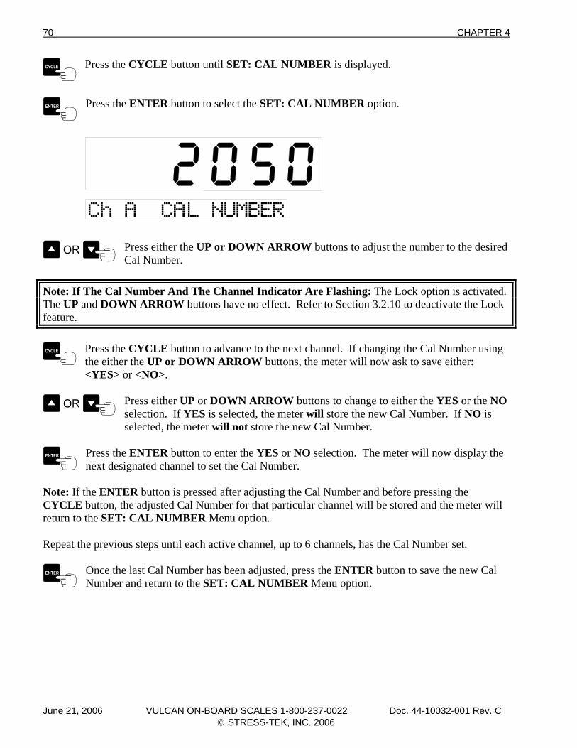
70 CHAPTER 4
Press the CYCLE button until SET: CAL NUMBER is displayed.
Press the ENTER button to select the SET: CAL NUMBER option.
Press either the UP or DOWN ARROW buttons to adjust the number to the desired Cal Number.
Note: If The Cal Number And The Channel Indicator Are Flashing: The Lock option is activated. The UP and DOWN ARROW buttons have no effect. Refer to Section 3.2.10 to deactivate the Lock feature.
Press the CYCLE button to advance to the next channel. If changing the Cal Number using the either the UP or DOWN ARROW buttons, the meter will now ask to save either:
<YES> or <NO>.
Press either UP or DOWN ARROW buttons to change to either the YES or the NO selection. If YES is selected, the meter will store the new Cal Number. If NO is
selected, the meter will not store the new Cal Number.
Press the ENTER button to enter the YES or NO selection. The meter will now display the next designated channel to set the Cal Number.
Note: If the ENTER button is pressed after adjusting the Cal Number and before pressing the CYCLE button, the adjusted Cal Number for that particular channel will be stored and the meter will return to the SET: CAL NUMBER Menu option. Repeat the previous steps until each active channel, up to 6 channels, has the Cal Number set.
Once the last Cal Number has been adjusted, press the ENTER button to save the new Cal Number and return to the SET: CAL NUMBER Menu option.
June 21, 2006 VULCAN ON-BOARD SCALES 1-800-237-0022 Doc. 44-10032-001 Rev. C © STRESS-TEK, INC. 2006
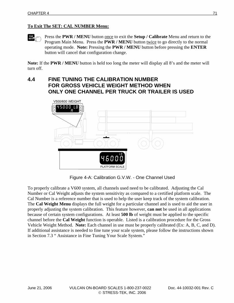
CHAPTER 4 71
To Exit The SET: CAL NUMBER Menu:
Press the PWR / MENU button once to exit the Setup / Calibrate Menu and return to the Program Main Menu. Press the PWR / MENU button twice to go directly to the normal operating mode. Note: Pressing the PWR / MENU button before pressing the ENTER button will cancel that configuration change.
Note: If the PWR / MENU button is held too long the meter will display all 8’s and the meter will turn off. 4.4 FINE TUNING THE CALIBRATION NUMBER FOR GROSS VEHICLE WEIGHT METHOD WHEN ONLY ONE CHANNEL PER TRUCK OR TRAILER IS USED
Figure 4-A: Calibration G.V.W. - One Channel Used
To properly calibrate a V600 system, all channels used need to be calibrated. Adjusting the Cal Number or Cal Weight adjusts the system sensitivity as compared to a certified platform scale. The Cal Number is a reference number that is used to help the user keep track of the system calibration. The Cal Weight Menu displays the full weight for a particular channel and is used to aid the user in properly adjusting the system calibration. This feature however, can not be used in all applications because of certain system configurations. At least 500 lb of weight must be applied to the specific channel before the Cal Weight function is operable. Listed is a calibration procedure for the Gross Vehicle Weight Method. Note: Each channel in use must be properly calibrated (Ex: A, B, C, and D). If additional assistance is needed to fine tune your scale system, please follow the instructions shown in Section 7.3 “ Assistance in Fine Tuning Your Scale System.”
June 21, 2006 VULCAN ON-BOARD SCALES 1-800-237-0022 Doc. 44-10032-001 Rev. C © STRESS-TEK, INC. 2006
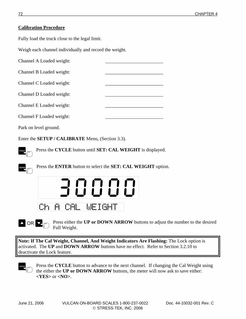
72 CHAPTER 4
Calibration Procedure Fully load the truck close to the legal limit. Weigh each channel individually and record the weight. Channel A Loaded weight: Channel B Loaded weight: Channel C Loaded weight: Channel D Loaded weight: Channel E Loaded weight: Channel F Loaded weight: Park on level ground. Enter the SETUP / CALIBRATE Menu, (Section 3.3).
Press the CYCLE button until SET: CAL WEIGHT is displayed.
Press the ENTER button to select the SET: CAL WEIGHT option.
Press either the UP or DOWN ARROW buttons to adjust the number to the desired Full Weight.
Note: If The Cal Weight, Channel, And Weight Indicators Are Flashing: The Lock option is activated. The UP and DOWN ARROW buttons have no effect. Refer to Section 3.2.10 to deactivate the Lock feature.
Press the CYCLE button to advance to the next channel. If changing the Cal Weight using the either the UP or DOWN ARROW buttons, the meter will now ask to save either:
<YES> or <NO>.
June 21, 2006 VULCAN ON-BOARD SCALES 1-800-237-0022 Doc. 44-10032-001 Rev. C © STRESS-TEK, INC. 2006
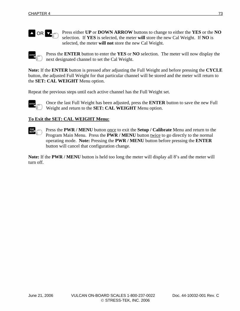
CHAPTER 4 73
Press either UP or DOWN ARROW buttons to change to either the YES or the NO selection. If YES is selected, the meter will store the new Cal Weight. If NO is
selected, the meter will not store the new Cal Weight.
Press the ENTER button to enter the YES or NO selection. The meter will now display the next designated channel to set the Cal Weight.
Note: If the ENTER button is pressed after adjusting the Full Weight and before pressing the CYCLE button, the adjusted Full Weight for that particular channel will be stored and the meter will return to the SET: CAL WEIGHT Menu option. Repeat the previous steps until each active channel has the Full Weight set.
Once the last Full Weight has been adjusted, press the ENTER button to save the new Full Weight and return to the SET: CAL WEIGHT Menu option.
To Exit the SET: CAL WEIGHT Menu:
Press the PWR / MENU button once to exit the Setup / Calibrate Menu and return to the Program Main Menu. Press the PWR / MENU button twice to go directly to the normal operating mode. Note: Pressing the PWR / MENU button before pressing the ENTER button will cancel that configuration change.
Note: If the PWR / MENU button is held too long the meter will display all 8’s and the meter will turn off.
June 21, 2006 VULCAN ON-BOARD SCALES 1-800-237-0022 Doc. 44-10032-001 Rev. C © STRESS-TEK, INC. 2006
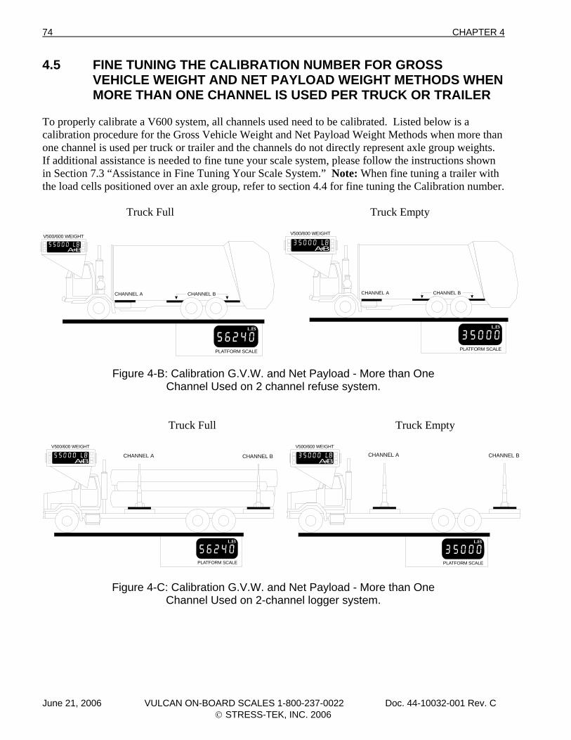
74 CHAPTER 4
4.5 FINE TUNING THE CALIBRATION NUMBER FOR GROSS VEHICLE WEIGHT AND NET PAYLOAD WEIGHT METHODS WHEN MORE THAN ONE CHANNEL IS USED PER TRUCK OR TRAILER To properly calibrate a V600 system, all channels used need to be calibrated. Listed below is a calibration procedure for the Gross Vehicle Weight and Net Payload Weight Methods when more than one channel is used per truck or trailer and the channels do not directly represent axle group weights. If additional assistance is needed to fine tune your scale system, please follow the instructions shown in Section 7.3 “Assistance in Fine Tuning Your Scale System.” Note: When fine tuning a trailer with the load cells positioned over an axle group, refer to section 4.4 for fine tuning the Calibration number. Truck Full Truck Empty
LB
PLATFORM SCALE
V500/600 WEIGHT
A+B
CHANNEL A CHANNEL B
Figure 4-B: Calibration G.V.W. and Net Payload - More than One Channel Used on 2 channel refuse system.
Truck Full Truck Empty
LB
PLATFORM SCALE
V500/600 WEIGHT
A+BCHANNEL A CHANNEL B
Figure 4-C: Calibration G.V.W. and Net Payload - More than One Channel Used on 2-channel logger system.
LB
PLATFORM SCALE
V500/600 WEIGHT
A+B
CHANNEL A CHANNEL B
LB
PLATFORM SCALE
V500/600 WEIGHT
A+BCHANNEL A CHANNEL B
June 21, 2006 VULCAN ON-BOARD SCALES 1-800-237-0022 Doc. 44-10032-001 Rev. C © STRESS-TEK, INC. 2006
CHAPTER 4 75
Calibration Procedure: Fully load the truck close to the legal limit. Lock the meter on the two channels being calibrated. Example: A+B. Weigh the loaded truck using a certified platform scale. Record the weight shown on the certified scale and the weight as shown on the V600 meter. a) Weight Shown on Certified Scale (truck fully loaded) ___________________________ (Example: 56,240 lb Certified Scale: truck fully loaded) b) Weight Shown on V600 meter (truck fully loaded for channels selected, Example:
A+B) ___________________________ (Example: 55,000 lb V600 Meter: truck fully loaded) Dump the payload. Weigh the empty truck on the same certified platform scale. Record the weight shown on the certified scale and the weight as shown on the V600 meter for the channels selected (Example: A+B). a) Weight Shown on Certified Scale (truck empty) ___________________________ (Example: 35,000 lb Certified Scale: truck empty) b) Weight Shown on V600 Meter (truck empty) for channels selected (Example: A+B) ___________________________ (Example: 35,000 lb V600 Meter: truck empty) Calculate the Net weights (P and V) from both the Certified Scale Readings (P) and the V600 meter readings (V). This is done by subtracting the empty weight from the fully loaded weight. P = Weight shown on Certified Scale (truck fully loaded) - Weight shown on Certified Scale (truck empty) Example: (P = 56,240 lb - 35,000 lb = 21,240 lb) V = Weight shown on V600 meter (truck fully loaded) - Weight shown on V600 meter (truck empty).
June 21, 2006 VULCAN ON-BOARD SCALES 1-800-237-0022 Doc. 44-10032-001 Rev. C © STRESS-TEK, INC. 2006
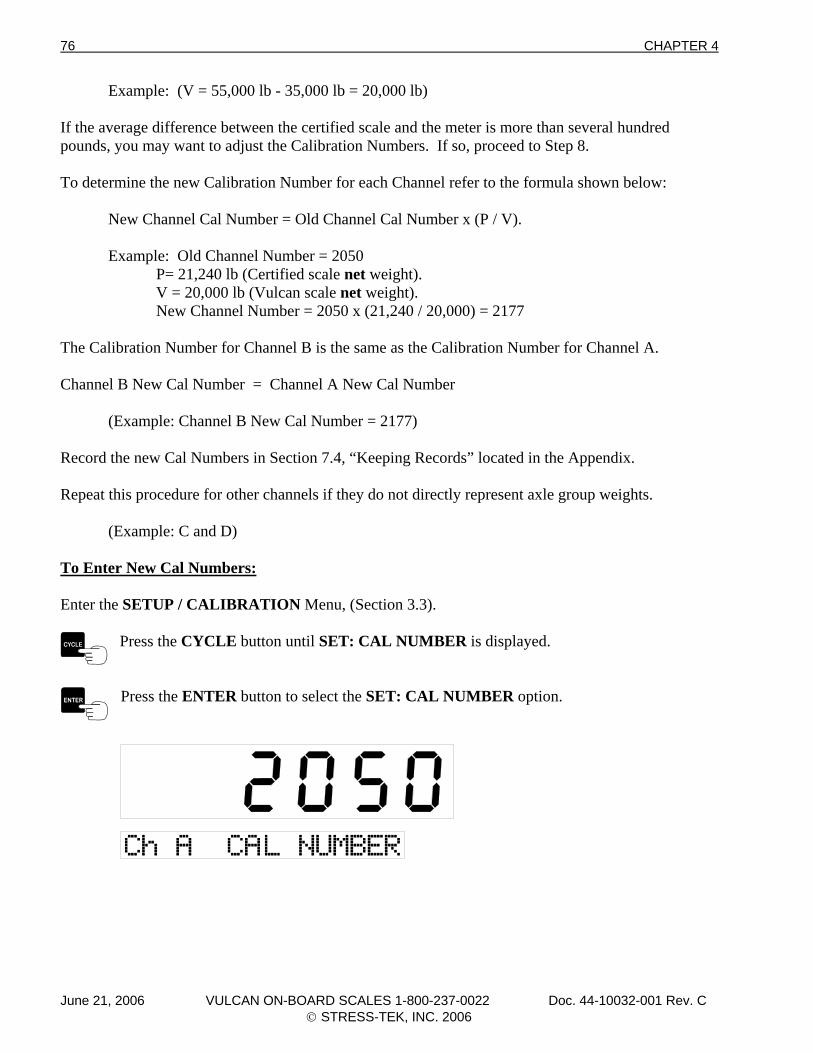
76 CHAPTER 4
Example: (V = 55,000 lb - 35,000 lb = 20,000 lb) If the average difference between the certified scale and the meter is more than several hundred pounds, you may want to adjust the Calibration Numbers. If so, proceed to Step 8. To determine the new Calibration Number for each Channel refer to the formula shown below: New Channel Cal Number = Old Channel Cal Number x (P / V). Example: Old Channel Number = 2050 P= 21,240 lb (Certified scale net weight). V = 20,000 lb (Vulcan scale net weight). New Channel Number = 2050 x (21,240 / 20,000) = 2177 The Calibration Number for Channel B is the same as the Calibration Number for Channel A. Channel B New Cal Number = Channel A New Cal Number (Example: Channel B New Cal Number = 2177) Record the new Cal Numbers in Section 7.4, “Keeping Records” located in the Appendix. Repeat this procedure for other channels if they do not directly represent axle group weights. (Example: C and D) To Enter New Cal Numbers: Enter the SETUP / CALIBRATION Menu, (Section 3.3).
Press the CYCLE button until SET: CAL NUMBER is displayed.
Press the ENTER button to select the SET: CAL NUMBER option.
June 21, 2006 VULCAN ON-BOARD SCALES 1-800-237-0022 Doc. 44-10032-001 Rev. C © STRESS-TEK, INC. 2006
CHAPTER 4 77
Press either the UP or DOWN ARROW buttons to adjust the number to the desired Cal Number. Note: Pressing the TARE / ZERO button will set the Cal Number to
“2050”.
Note: If The Cal Number, And The Channel Indicator Are Flashing: The Lock option is activated. The UP and DOWN ARROW buttons have no effect. Refer to Section 3.2.10 to deactivate the Lock feature.
Press the CYCLE button to advance to the next channel. If changing the Cal Number using the either the UP or DOWN ARROW buttons or the TARE / ZERO button, the meter will
now ask to save, either <YES> or <NO>.
Press either UP or DOWN ARROW buttons to change to either the YES or the NO selection. If YES is selected, the meter will store the new Cal Number. If NO is
selected, the meter will not store the new Cal Number.
Press the ENTER button to enter the YES or NO selection. The meter will now display the next designated channel to set the Cal Number.
Note: If the ENTER button is pressed after adjusting the Cal Number and before pressing the CYCLE button, the adjusted Cal Number for that particular channel will be stored and the meter will return to the SET: CAL NUMBER Menu option. Repeat the previous steps until each active channel, up to 6 channels, has the Cal Number set.
Once the last Cal Number has been adjusted, press the ENTER button to save the new Cal Number and return to the SET: CAL NUMBER Menu option.
To Exit the SET: CAL NUMBER Menu:
Press the PWR / MENU button once to exit the Setup / Calibrate Menu and return to the Program Main Menu. Press the PWR / MENU button twice to go directly to the normal operating mode. Note: Pressing the PWR / MENU button before pressing the ENTER button will cancel that configuration change.
Note: If the PWR / MENU button is held too long the meter will display all 8’s and the meter will turn off.
June 21, 2006 VULCAN ON-BOARD SCALES 1-800-237-0022 Doc. 44-10032-001 Rev. C © STRESS-TEK, INC. 2006
78 CHAPTER 4
June 21, 2006 VULCAN ON-BOARD SCALES 1-800-237-0022 Doc. 44-10032-001 Rev. C © STRESS-TEK, INC. 2006
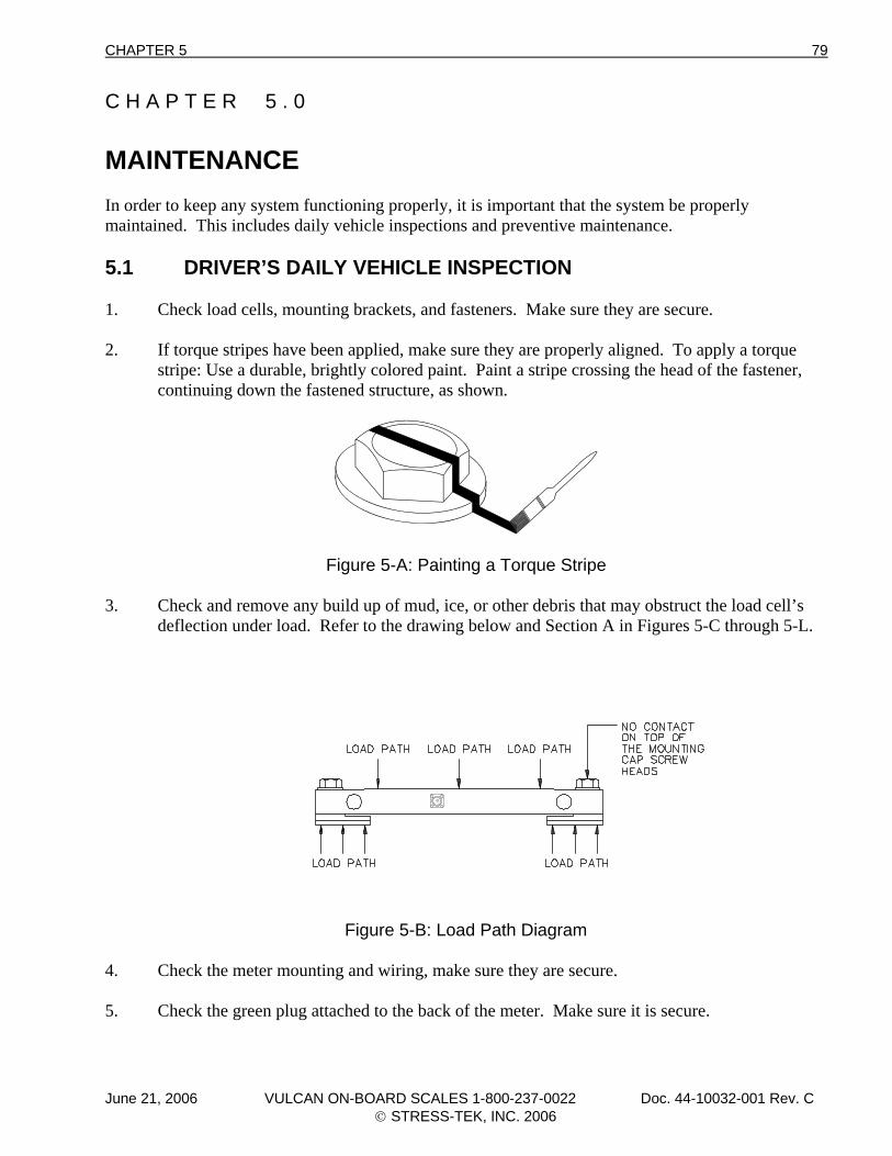
CHAPTER 5 79
C H A P T E R 5 . 0 MAINTENANCE In order to keep any system functioning properly, it is important that the system be properly maintained. This includes daily vehicle inspections and preventive maintenance. 5.1 DRIVER’S DAILY VEHICLE INSPECTION 1. Check load cells, mounting brackets, and fasteners. Make sure they are secure. 2. If torque stripes have been applied, make sure they are properly aligned. To apply a torque stripe: Use a durable, brightly colored paint. Paint a stripe crossing the head of the fastener, continuing down the fastened structure, as shown.
Figure 5-A: Painting a Torque Stripe
3. Check and remove any build up of mud, ice, or other debris that may obstruct the load cell’s deflection under load. Refer to the drawing below and Section A in Figures 5-C through 5-L.
Figure 5-B: Load Path Diagram
4. Check the meter mounting and wiring, make sure they are secure. 5. Check the green plug attached to the back of the meter. Make sure it is secure.
June 21, 2006 VULCAN ON-BOARD SCALES 1-800-237-0022 Doc. 44-10032-001 Rev. C © STRESS-TEK, INC. 2006
80 CHAPTER 5
6. Check the system. Make sure the meter powers up after it has been turned on, digits are legible, and the system functions normally.
7. Check all wiring for condition (no cracks or splits), security, chaffing, and protection from possible damage. 8. Fixed body trucks: Make sure body springs are intact and bolt locks are in place. 9. Tipper type trucks: Check the load cell bearing pads. Make sure they are not worn out and properly aligned and greased. Make sure bolt locks are in place, hinge pins are not bent, and body guides are intact. 5.2 PREVENTIVE MAINTENANCE AND VULCAN TORQUE SPECIFICATIONS The following simple, but important, preventive maintenance steps must be performed periodically. For example, after the first 500 miles, then monthly, or more frequently, if needed. 1. Look for mud, ice build up, or other debris between the load cell and bracket. Refer to
location A shown on Figures 5-C through 5-L. 2. Check load cell connectors (refer to location B shown on Figures 5-C through 5-L), make
sure they are finger tight plus an additional 1/8 of a turn with channel lock pliers. The additional tightening is necessary to prevent scale errors, which can occur from moisture entering into the load cell connector. Do not grease or lubricate inside the Vulcan load cell connector or VSL Vulcoder connector. These components are highly sensitive to foreign substances and inaccurate readings will occur if these components are contaminated. Your manufacturer’s warranty does not cover the failure of Vulcan components due to contamination (use of grease or other conductive substance) in either the Vulcan load cell connectors or VSL Vulcoder connectors. If a connector is opened for any reason, you must clean the load cell connector and cable connector with cotton swabs and isopropyl alcohol, dry with a hair dryer (DO NOT OVERHEAT), and replace the O-ring before reconnecting.
3. Check the torque on load cell cap screws monthly. New trucks must be checked once a week
for 2 weeks. Vulcan On-Board Scales recommended torque values are shown on Figures 5-C through 5-L and general torque values shown below. As a method of monitoring changes in fastener torque, Vulcan On-Board Scales recommends applying torque stripes to all fasteners (see Section 5.1, step 2).
Torque Specifications: 3/4" 7/8" 1" 1-1/8" 1-1/4" lb-ft 400-500 400-590 650-890 1000-1400 1450-1780
June 21, 2006 VULCAN ON-BOARD SCALES 1-800-237-0022 Doc. 44-10032-001 Rev. C © STRESS-TEK, INC. 2006
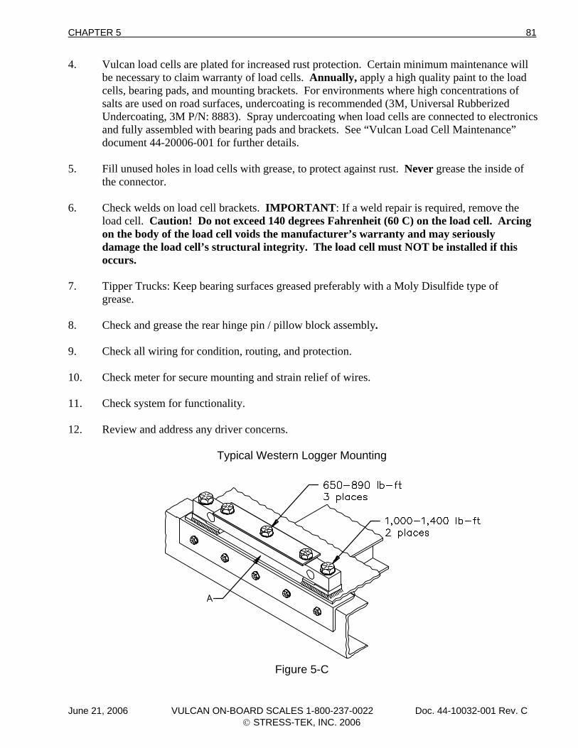
CHAPTER 5 81
4. Vulcan load cells are plated for increased rust protection. Certain minimum maintenance will be necessary to claim warranty of load cells. Annually, apply a high quality paint to the load cells, bearing pads, and mounting brackets. For environments where high concentrations of salts are used on road surfaces, undercoating is recommended (3M, Universal Rubberized Undercoating, 3M P/N: 8883). Spray undercoating when load cells are connected to electronics and fully assembled with bearing pads and brackets. See “Vulcan Load Cell Maintenance” document 44-20006-001 for further details.
5. Fill unused holes in load cells with grease, to protect against rust. Never grease the inside of
the connector. 6. Check welds on load cell brackets. IMPORTANT: If a weld repair is required, remove the
load cell. Caution! Do not exceed 140 degrees Fahrenheit (60 C) on the load cell. Arcing on the body of the load cell voids the manufacturer’s warranty and may seriously damage the load cell’s structural integrity. The load cell must NOT be installed if this occurs.
7. Tipper Trucks: Keep bearing surfaces greased preferably with a Moly Disulfide type of grease. 8. Check and grease the rear hinge pin / pillow block assembly. 9. Check all wiring for condition, routing, and protection. 10. Check meter for secure mounting and strain relief of wires. 11. Check system for functionality. 12. Review and address any driver concerns.
Typical Western Logger Mounting
Figure 5-C
June 21, 2006 VULCAN ON-BOARD SCALES 1-800-237-0022 Doc. 44-10032-001 Rev. C © STRESS-TEK, INC. 2006
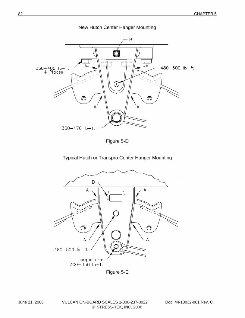
82 CHAPTER 5
New Hutch Center Hanger Mounting
Figure 5-D
Typical Hutch or Transpro Center Hanger Mounting
Figure 5-E
June 21, 2006 VULCAN ON-BOARD SCALES 1-800-237-0022 Doc. 44-10032-001 Rev. C © STRESS-TEK, INC. 2006
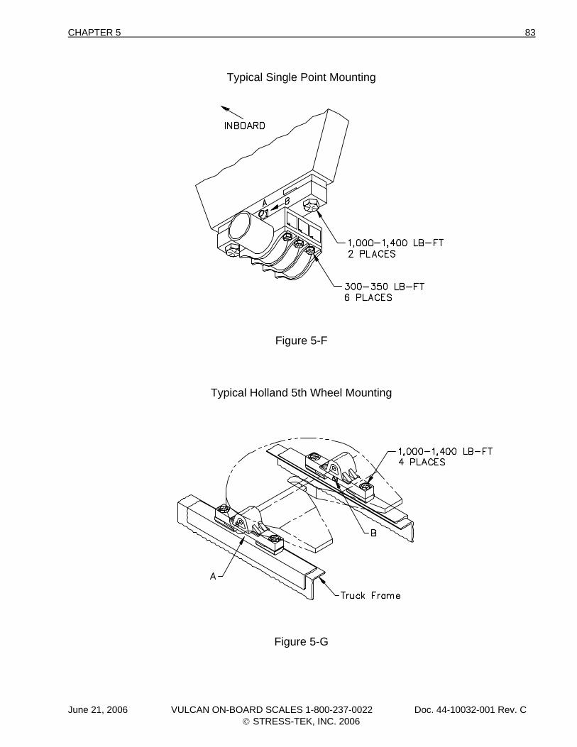
CHAPTER 5 83
Typical Single Point Mounting
Figure 5-F
Typical Holland 5th Wheel Mounting
Figure 5-G
June 21, 2006 VULCAN ON-BOARD SCALES 1-800-237-0022 Doc. 44-10032-001 Rev. C © STRESS-TEK, INC. 2006
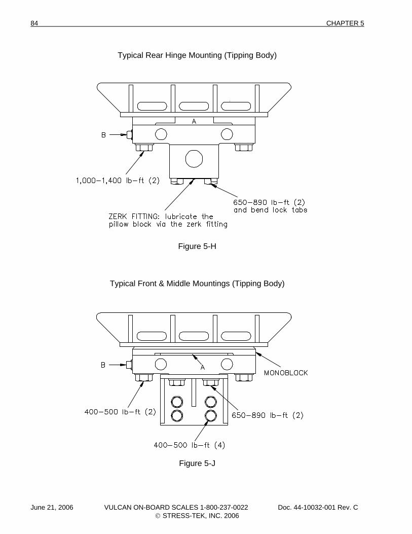
84 CHAPTER 5
Typical Rear Hinge Mounting (Tipping Body)
Figure 5-H
Typical Front & Middle Mountings (Tipping Body)
Figure 5-J
June 21, 2006 VULCAN ON-BOARD SCALES 1-800-237-0022 Doc. 44-10032-001 Rev. C © STRESS-TEK, INC. 2006
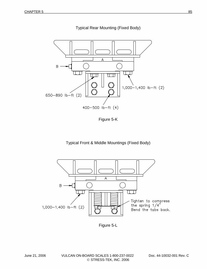
CHAPTER 5 85
Typical Rear Mounting (Fixed Body)
Figure 5-K
Typical Front & Middle Mountings (Fixed Body)
Figure 5-L
June 21, 2006 VULCAN ON-BOARD SCALES 1-800-237-0022 Doc. 44-10032-001 Rev. C © STRESS-TEK, INC. 2006

86 CHAPTER 5
June 21, 2006 VULCAN ON-BOARD SCALES 1-800-237-0022 Doc. 44-10032-001 Rev. C © STRESS-TEK, INC. 2006
CHAPTER 6 87
C H A P T E R 6 . 0 TROUBLESHOOTING In general, troubleshooting is a systematic process of testing and eliminating potential problem sources until the one that is causing the problem is found. The problem can then be fixed by repairing or replacing the faulty part. With a little knowledge and by following a step by step procedure, most of the problems that you may encounter will be easy to diagnose and solve. In this section, you will find guidelines on how to troubleshoot the system, some characteristics of a properly functioning system, and where to look when certain problems occur. Occasionally, someone has a problem that is not described here. Do not panic. By approaching the problem systematically, you will be able to eliminate potential sources of trouble until you find the one that is causing the problem. The following section covers an explanation of V600 Test Procedures, Load Cell Evaluation Test Procedures and Vulcan Error Codes. If a problem occurs and no Error Codes appear, use the V600 meter to isolate the problem to the appropriate channel.
June 21, 2006 VULCAN ON-BOARD SCALES 1-800-237-0022 Doc. 44-10032-001 Rev. C © STRESS-TEK, INC. 2006
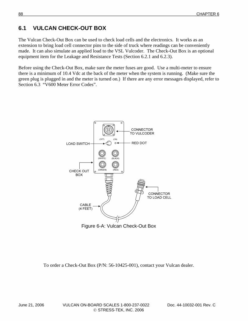
88 CHAPTER 6
6.1 VULCAN CHECK-OUT BOX The Vulcan Check-Out Box can be used to check load cells and the electronics. It works as an extension to bring load cell connector pins to the side of truck where readings can be conveniently made. It can also simulate an applied load to the VSL Vulcoder. The Check-Out Box is an optional equipment item for the Leakage and Resistance Tests (Section 6.2.1 and 6.2.3). Before using the Check-Out Box, make sure the meter fuses are good. Use a multi-meter to ensure there is a minimum of 10.4 Vdc at the back of the meter when the system is running. (Make sure the green plug is plugged in and the meter is turned on.) If there are any error messages displayed, refer to Section 6.3 “V600 Meter Error Codes”.
Figure 6-A: Vulcan Check-Out Box
To order a Check-Out Box (P/N: 56-10425-001), contact your Vulcan dealer.
June 21, 2006 VULCAN ON-BOARD SCALES 1-800-237-0022 Doc. 44-10032-001 Rev. C © STRESS-TEK, INC. 2006
CHAPTER 6 89
6.2 LOAD CELL EVALUATION TESTS The tests listed below will help identify and locate any problem you may encounter with your Vulcan load cells. Leakage Test Tare Test Resistance Test 6.2.1 LEAKAGE TEST PROCEDURE Required Equipment: Digital Multi-Meter With Conductivity Scale Isopropyl Alcohol Cotton Swabs Hair Dryer Optional Equipment: Vulcan Check-Out Box The Leakage Test Procedure detects the presence of moisture that could cause erratic meter readings. The way to measure leakage is to use a digital multi-meter that has a conductivity scale. Electrical isolation is measured between any pin and an unpainted clean surface on the load cell or the connector body. Electrical isolation must not exceed 2.0 nS (nano-siemans) or be less than 500 Meg Ohms. Refer to Figure 6-B for the Leakage Test equipment setup. If a Vulcan Check-Out Box is used, it is important that the VSL Vulcoder leads from the load cells of the channel being tested are disconnected. For proper operation, the power and signal leads from the load cell must have a very high resistance to the load cell body. An electrical path between the wires and the body would indicate moisture in the cell or shorting to the body. This would result in erratic, fluctuating, or even out of range weight displays. If the load cell fails (electrical isolation is greater than 2.0 nS or is less that 500 Meg Ohms), check the inside of the load cell connector with a dry cotton swab to make sure it is clean and dry. If not, clean with isopropyl alcohol, dry with a hair dryer, and check the electrical isolation again. If the load cell cannot be brought to Vulcan specifications, contact your Vulcan dealer.
June 21, 2006 VULCAN ON-BOARD SCALES 1-800-237-0022 Doc. 44-10032-001 Rev. C © STRESS-TEK, INC. 2006
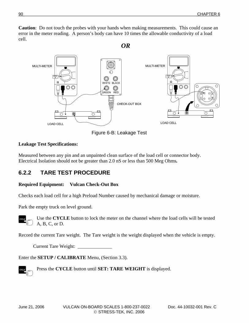
90 CHAPTER 6
Caution: Do not touch the probes with your hands when making measurements. This could cause an error in the meter reading. A person’s body can have 10 times the allowable conductivity of a load cell. OR
Figure 6-B: Leakage Test Leakage Test Specifications: Measured between any pin and an unpainted clean surface of the load cell or connector body. Electrical Isolation should not be greater than 2.0 nS or less than 500 Meg Ohms. 6.2.2 TARE TEST PROCEDURE Required Equipment: Vulcan Check-Out Box Checks each load cell for a high Preload Number caused by mechanical damage or moisture. Park the empty truck on level ground.
Use the CYCLE button to lock the meter on the channel where the load cells will be tested A, B, C, or D.
Record the current Tare weight. The Tare weight is the weight displayed when the vehicle is empty. Current Tare Weight: ______________ Enter the SETUP / CALIBRATE Menu, (Section 3.3).
Press the CYCLE button until SET: TARE WEIGHT is displayed.
June 21, 2006 VULCAN ON-BOARD SCALES 1-800-237-0022 Doc. 44-10032-001 Rev. C © STRESS-TEK, INC. 2006
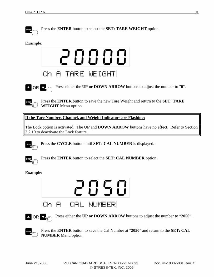
CHAPTER 6 91
Press the ENTER button to select the SET: TARE WEIGHT option.
Example:
Press either the UP or DOWN ARROW buttons to adjust the number to "0".
Press the ENTER button to save the new Tare Weight and return to the SET: TARE WEIGHT Menu option.
If the Tare Number, Channel, and Weight Indicators are Flashing: The Lock option is activated. The UP and DOWN ARROW buttons have no effect. Refer to Section 3.2.10 to deactivate the Lock feature.
Press the CYCLE button until SET: CAL NUMBER is displayed.
Press the ENTER button to select the SET: CAL NUMBER option.
Example:
Press either the UP or DOWN ARROW buttons to adjust the number to “2050”.
Press the ENTER button to save the Cal Number at "2050" and return to the SET: CAL NUMBER Menu option.
June 21, 2006 VULCAN ON-BOARD SCALES 1-800-237-0022 Doc. 44-10032-001 Rev. C © STRESS-TEK, INC. 2006
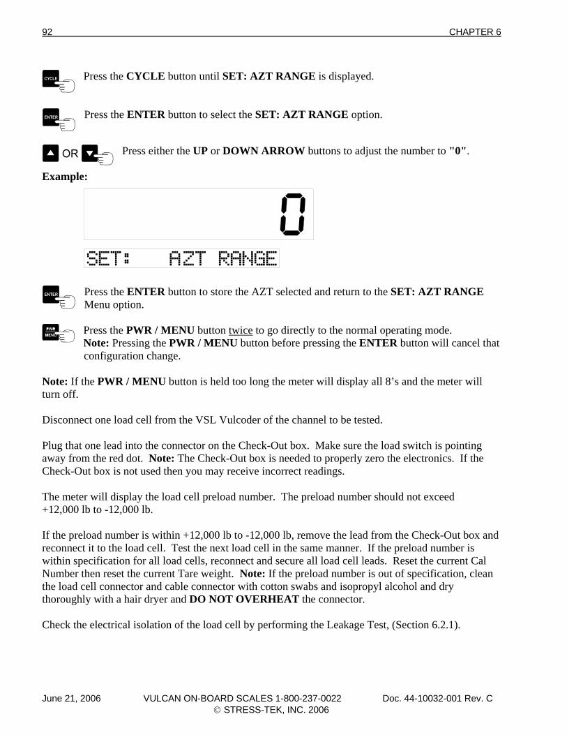
92 CHAPTER 6
Press the CYCLE button until SET: AZT RANGE is displayed.
Press the ENTER button to select the SET: AZT RANGE option.
Press either the UP or DOWN ARROW buttons to adjust the number to "0".
Example:
Press the ENTER button to store the AZT selected and return to the SET: AZT RANGE Menu option.
Press the PWR / MENU button twice to go directly to the normal operating mode. Note: Pressing the PWR / MENU button before pressing the ENTER button will cancel that
configuration change.
Note: If the PWR / MENU button is held too long the meter will display all 8’s and the meter will turn off. Disconnect one load cell from the VSL Vulcoder of the channel to be tested. Plug that one lead into the connector on the Check-Out box. Make sure the load switch is pointing away from the red dot. Note: The Check-Out box is needed to properly zero the electronics. If the Check-Out box is not used then you may receive incorrect readings. The meter will display the load cell preload number. The preload number should not exceed +12,000 lb to -12,000 lb. If the preload number is within +12,000 lb to -12,000 lb, remove the lead from the Check-Out box and reconnect it to the load cell. Test the next load cell in the same manner. If the preload number is within specification for all load cells, reconnect and secure all load cell leads. Reset the current Cal Number then reset the current Tare weight. Note: If the preload number is out of specification, clean the load cell connector and cable connector with cotton swabs and isopropyl alcohol and dry thoroughly with a hair dryer and DO NOT OVERHEAT the connector. Check the electrical isolation of the load cell by performing the Leakage Test, (Section 6.2.1).
June 21, 2006 VULCAN ON-BOARD SCALES 1-800-237-0022 Doc. 44-10032-001 Rev. C © STRESS-TEK, INC. 2006
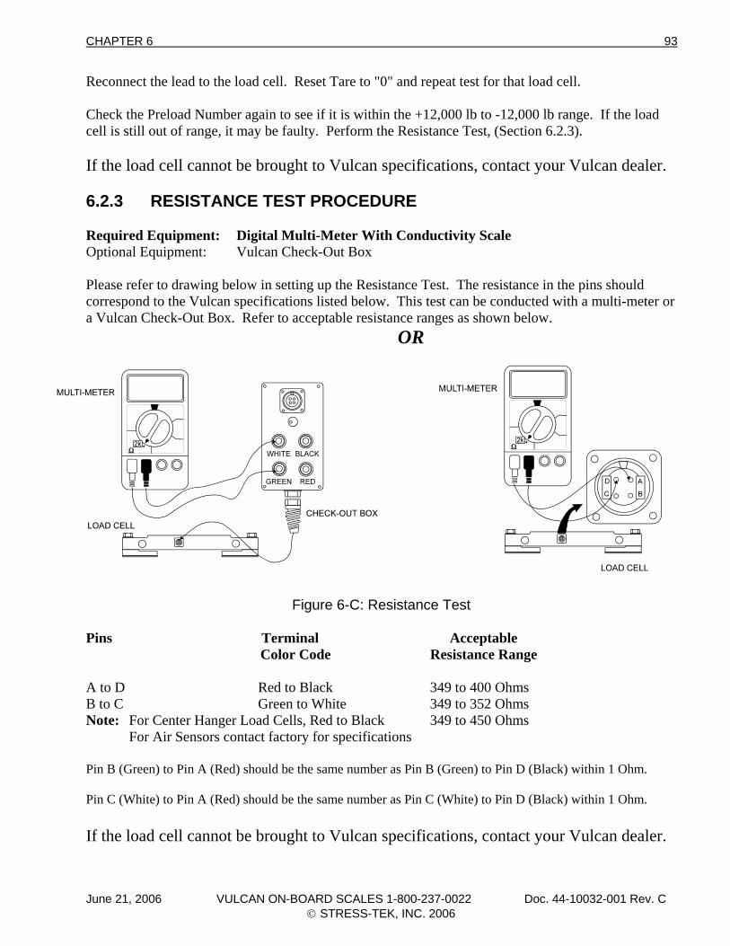
CHAPTER 6 93
Reconnect the lead to the load cell. Reset Tare to "0" and repeat test for that load cell. Check the Preload Number again to see if it is within the +12,000 lb to -12,000 lb range. If the load cell is still out of range, it may be faulty. Perform the Resistance Test, (Section 6.2.3). If the load cell cannot be brought to Vulcan specifications, contact your Vulcan dealer. 6.2.3 RESISTANCE TEST PROCEDURE Required Equipment: Digital Multi-Meter With Conductivity Scale Optional Equipment: Vulcan Check-Out Box Please refer to drawing below in setting up the Resistance Test. The resistance in the pins should correspond to the Vulcan specifications listed below. This test can be conducted with a multi-meter or a Vulcan Check-Out Box. Refer to acceptable resistance ranges as shown below. OR
Figure 6-C: Resistance Test
Pins Terminal Acceptable Color Code Resistance Range A to D Red to Black 349 to 400 Ohms B to C Green to White 349 to 352 Ohms Note: For Center Hanger Load Cells, Red to Black 349 to 450 Ohms For Air Sensors contact factory for specifications Pin B (Green) to Pin A (Red) should be the same number as Pin B (Green) to Pin D (Black) within 1 Ohm. Pin C (White) to Pin A (Red) should be the same number as Pin C (White) to Pin D (Black) within 1 Ohm. If the load cell cannot be brought to Vulcan specifications, contact your Vulcan dealer.
June 21, 2006 VULCAN ON-BOARD SCALES 1-800-237-0022 Doc. 44-10032-001 Rev. C © STRESS-TEK, INC. 2006
94 CHAPTER 6
6.3 V600 METER ERROR CODES 6.3.1 Err 01 Indicates that the VSL Vulcoder is processing an over-ranged signal. An over-ranged signal means that the load cell output is greater than the maximum that the VSL Vulcoder will accept. Possible Causes: 1. The load cells are being over-loaded. 2. There is moisture in a load cell connector. 3. One of the VSL Vulcoder-to load cell cables has been damaged. 4. A load cell has a large Preload Number. 5. A load cell is faulty. What to Do: 1. Perform the Tare Test, (Section 6.2.2). 2. Check the load cells. Check by disconnecting one load cell at a time. When the faulty load cell has been disconnected, the meter will read a number instead of the error code. 3. Check mounting of the load cell per Section 5.2 “Preventive Maintenance and Vulcan Torque Specifications”. 6.3.2 Err 02 Indicates that the reading to be displayed is beyond the limitations of the meter’s display. Possible Causes: 1. Cal Number set too high. 2. Tare Weight set too high. What to Do: 1. Check and reset the Cal Numbers and Tare weight.
June 21, 2006 VULCAN ON-BOARD SCALES 1-800-237-0022 Doc. 44-10032-001 Rev. C © STRESS-TEK, INC. 2006
CHAPTER 6 95
6.3.3 Err 03 Indicates that the meter is not receiving a weight from the VSL Vulcoder. Possible Causes: 1. New installation 2. Communication problem between Meter and VSL Vulcoder 3. Dirty or worn truck to trailer connectors. 4. Cables have been disconnected or damaged. 5. Green and white leads reversed on VSL Vulcoder line. 6. Multiple front or rear Vulcoders for one channel 7. Faulty VSL Vulcoder 8. Faulty Meter What to Do: 1. Verify if affected channel is still sequenced, manually sequence if necessary, (Section 3.4.1). 2. Reconnect any cables that have become disconnected. 3. Clean any dirt, mud or ice out of 4 - pin truck to trailer connectors. 4. Inspect VSL Vulcoder Communication line for cut or broken wires and proper connection of
the green and white wires. To check for an open VSL line, ohm the VSL Vulcoder line by twisting the green and white wires together at the back of the meter and disconnect each Vulcoder from the VSL Vulcoder line. There should be no resistance detected when measuring between the green and white wires at the Vulcoder hook up point.
5. Inspect truck to trailer connecting plug and receptacles for good connection. Spread and clean
pins in receptacle and plug if needed. 6. Run Test 2 from the V600 Meter Test Procedures, (Section 3.5.3). 7. VSL Vulcoder is damaged, replace VSL Vulcoder. 6.3.4 Err 04 Indicates that the VSL Vulcoder is not calibrated. Possible Causes: 1. Cal or Tare Numbers are not entered.
June 21, 2006 VULCAN ON-BOARD SCALES 1-800-237-0022 Doc. 44-10032-001 Rev. C © STRESS-TEK, INC. 2006
96 CHAPTER 6
What to Do: 1. Check and reset the Cal Numbers and Tare weight. 6.3.5 Err 05 Indicates that the VSL Vulcoder has a hardware problem. Possible Causes: 1. VSL Vulcoder hardware component is damaged. What to do: 1. Press the PWR / MENU button to turn the meter off and then press PWR / MENU again to turn it on. This may reset the meter and eliminate the error. 2. Inspect VSL Vulcoder Communication line for cut or broken wires.
3. Run Test 2 from the V600 Meter Test Procedures, (Section 3.5.3). 4. VSL Vulcoder is damaged, replace VSL Vulcoder. 6.3.6 Err 06 Indicates that the VSL Vulcoder is processing an under-ranged signal. An under-ranged signal means that the load cell output is less than the minimum that the VSL Vulcoder will accept. Possible Causes: 1. There is moisture in a load cell connector. 2. One of the VSL Vulcoder-to load cell cables has been damaged. 3. No load cells are connected to the VSL Vulcoder. 4. A load cell is faulty. What to Do: 1. Check to see that the load cells are properly connected to the VSL Vulcoder. 2. Check the load cells. Check by disconnecting one load cell at a time. When the faulty load cell has been disconnected, the meter will read a number instead of the error code. 3. Check mounting of the load cell per Section 5.2 “Preventive Maintenance and Vulcan Torque Specifications”. 4. Perform the Tare Test, (Section 6.2.2).
June 21, 2006 VULCAN ON-BOARD SCALES 1-800-237-0022 Doc. 44-10032-001 Rev. C © STRESS-TEK, INC. 2006
CHAPTER 6 97
6.3.7 Err 07 Indicates that a new VSL Vulcoder has been detected or multiple VSL Vulcoders with the same channel designation have been found. Possible Causes: 1. Multiple VSL Vulcoders with the same channel ID have been found. 2. Line Noise. What to Do: 1. System needs to be manually sequenced. Be sure that on two or more channel systems, there is at least one rear VSL Vulcoder, and it is the last VSL Vulcoder in the system. 2. Turn the meter off and then on to cycle power in system. 3. Faulty VSL Vulcoder 6.3.8 Err 08 Indicates that the meter has found multiple front VSL Vulcoders. Possible Causes: 1. More than one front VSL Vulcoder is attached at the same time. (During sequencing or powering up the meter). What to Do: 1. Disconnect the VSL Vulcoders and then reconnect. 2. Manually sequence the system. 3. See electronics installation section for proper installation procedure, (Section 1.6).
June 21, 2006 VULCAN ON-BOARD SCALES 1-800-237-0022 Doc. 44-10032-001 Rev. C © STRESS-TEK, INC. 2006
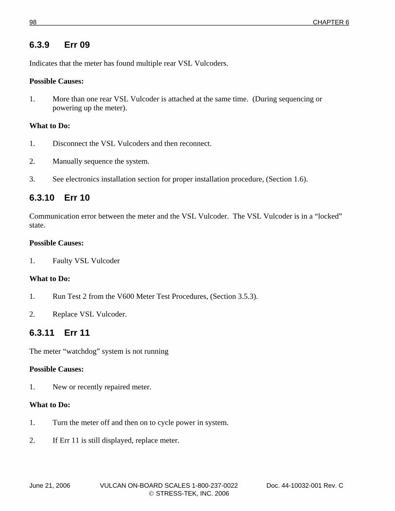
98 CHAPTER 6
6.3.9 Err 09 Indicates that the meter has found multiple rear VSL Vulcoders. Possible Causes: 1. More than one rear VSL Vulcoder is attached at the same time. (During sequencing or powering up the meter). What to Do: 1. Disconnect the VSL Vulcoders and then reconnect. 2. Manually sequence the system. 3. See electronics installation section for proper installation procedure, (Section 1.6). 6.3.10 Err 10 Communication error between the meter and the VSL Vulcoder. The VSL Vulcoder is in a “locked” state. Possible Causes: 1. Faulty VSL Vulcoder What to Do: 1. Run Test 2 from the V600 Meter Test Procedures, (Section 3.5.3). 2. Replace VSL Vulcoder. 6.3.11 Err 11 The meter “watchdog” system is not running Possible Causes: 1. New or recently repaired meter. What to Do: 1. Turn the meter off and then on to cycle power in system. 2. If Err 11 is still displayed, replace meter.
June 21, 2006 VULCAN ON-BOARD SCALES 1-800-237-0022 Doc. 44-10032-001 Rev. C © STRESS-TEK, INC. 2006
CHAPTER 6 99
6.4 SYSTEM MALFUNCTIONS 6.4.1 CONDITION: No Indicator Display Or Function Lights Possible Causes: 1. Power switch turned off. 2. Power to the meter has been disconnected. 3. Bad meter cable connections to the battery. 4. Battery is low (under 10.5 Volts). 5. A fuse is blown in the power or ground cable. 6. Faulty power switch. 7. Faulty Meter. 8. Reversed polarity. What to Do: 1. Check the power to the meter. When the meter is turned on and off, the power should not
change more than 1/2 Volt. Turn off the meter either by the key or truck battery switch for a few seconds and then turn on again. If the meter still does not work, proceed to step 2.
2. Check the fuses for both negative and positive leads. Use 2 amp fast blow fuses for 12 Vdc
applications and 1 amp fast blow fuses for 24 Vdc applications. 3. Check that the power supply wires are attached correctly at the 12 Volt power source and to the
green connector at the back of the meter. Check the battery connections for corrosion. 4. If a spare meter is available, the quickest and easiest next step is to exchange the meter. If the
new meter works, try the old meter again. If the old meter now works, the problem was likely the meter’s internal circuit breaker. If both the old meter and the new meter do not work, the problem is most likely in the power source (battery, meter power cable, or fuses). If the new meter works, but the old one doesn’t, the old meter is faulty.
If you do not have a spare meter, disconnect then reconnect the green power plug on the back
of the meter. If the meter doesn’t work, then check the power source (battery, meter power cable, or fuses). If the power sources check out, then the meter is faulty.
June 21, 2006 VULCAN ON-BOARD SCALES 1-800-237-0022 Doc. 44-10032-001 Rev. C © STRESS-TEK, INC. 2006
100 CHAPTER 6
6.4.2 CONDITION: Unable To Enter Tare Or Calibration Numbers Possible Causes: 1. Meter may be in the Driver Lockout mode, which does not allow the Tare weight, Cal Number, or Cal weight to be changed. 2. Faulty Meter What to Do: 1. The Lock feature may be enabled see Section 3.2.10 “Setting The Lock”. 2. Make sure the Vulcoder is connected to all the load cells. 3. Unplug the green connector at the back of the meter for a few seconds, re-plug it in and try to enter the Tare or Cal Numbers again. 4. Possible faulty meter buttons. Run the Key pad test in section 3.5.1. 6.4.3 CONDITION: Meter Reading Drifts or Wanders With Time Possible Causes: 1. Voltage to meter is less than 10.5 Volts. 2. Voltage out of the VSL Vulcoder is less than the Voltage Output required as stated in Section
7.2 “System Specifications.” 3. Moisture in a load cell connector. 4. Damaged cable between VSL Vulcoder and load cell. 5. Bad connection on green connector or broken wire or cable between meter and the VSL
Vulcoder. 6. Faulty load cell What to Do: 1. Using a voltmeter, check the voltage at the back of the meter. Refer to the required meter voltages in Section 7.2 “System Specifications.” 2. Check the black 4-wire cabling between the load cells and the VSL Vulcoder. If the cabling is damaged, contact your Vulcan dealer for VSL Vulcoder repair or repair kit. 3. Measure the voltage between pins A and D of the VSL Vulcoder connector. If it measures less
than 5 Volts make sure the VSL Vulcoder cable is securely attached to the meter green plug and the length of the orange cable from the VSL Vulcoder to the meter isn’t longer than 100 ft. Also check any truck / trailer connectors in the VSL Vulcoder signal cable.
June 21, 2006 VULCAN ON-BOARD SCALES 1-800-237-0022 Doc. 44-10032-001 Rev. C © STRESS-TEK, INC. 2006
CHAPTER 6 101
4. Before proceeding, clean the load cell connector and cable connector with isopropyl alcohol and cotton swabs, then dry with a hair dryer. Do not overheat. Reconnect and operate the system for one day to see if the problem is fixed. If the problem is not fixed, continue to step. 5. If two load cells are connected per VSL Vulcoder, follow steps 5a and 5b. a. Disconnect the cable to the right load cell. Watch the meter display the number for a period of 5 minutes. If it wanders more than 200 lb (100 kg), make a note of it. Then clean and reconnect the right load cell. b. Disconnect the cable to the left load cell. Watch the meter display the number for
period of 5 minutes. If it wanders more than 200 lb (100 kg), make a note of it. Then clean and reconnect the left load cell.
If any one of the load cells wanders more than 200 lb (100 kg), perform the Leakage and Resistance tests, (Section 6.2.1 and 6.2.3). If both of the load cells wanders more than 200 lb (100 kg), then the VSL Vulcoder may be faulty and needs to be checked, (Section 6.3.4 “VSL Vulcoder Check-Out Procedure”). If four load cells are connected per VSL Vulcoder, follow steps 5c through 5f. c. For VSL Vulcoders with 4 load cells, disconnect the cables to all the load cells except
the right front load cell. Watch the meter display a number for a period of 5 minutes. If it wanders more than 200 lb (100 kg), make a note of it.
d. Disconnect right front load cell and reconnect right rear load cell. Watch the meter display for 5 minutes. If it wanders more than 200 lb (100 kg), make a note of it. e. Disconnect the right rear load cell and reconnect the left rear load cell. Watch the meter display for 5 minutes. If it wanders more than 200 lb (100 kg), make a note of it. f. Disconnect the left rear load cell and reconnect the left front load cell. Watch the meter
display for 5 minutes. If it wanders more than 200 lb (100 kg), make a note of it. If any one of the load cells wanders more than 200 lb (100 kg), perform the Leakage and Resistance tests, (Sections 6.2.1 and 6.2.3). If all the load cells wander more than 200 lb (100 kg) then the VSL Vulcoder may be faulty and needs to be checked (Section 6.2.4 “VSL Vulcoder Check-Out Procedure”).
June 21, 2006 VULCAN ON-BOARD SCALES 1-800-237-0022 Doc. 44-10032-001 Rev. C © STRESS-TEK, INC. 2006
102 CHAPTER 6
6.4.4 CONDITION: Meter Reading Does Not Change When Truck is Being Loaded Possible Causes: 1. Voltage to meter is below 10.5 Volts. 2. Mud or ice build-up under the load cells. 3. Calibration Number on the meter is set too low. 4. Faulty load cell. 5. Broken wire or bad connection between the load cell and VSL Vulcoder. 6. Meter display is locked. What to Do: 1. Using a voltmeter, check the power at the meter’s green plug at the back of the meter. Refer to
Section 7.2 “System Specifications”. If the voltage is below 10.5 Vdc, the problem could be in the power source (battery, meter power cable, and / or fuses).
2. Reset the meter by unplugging the green connection on the back of the meter for a few seconds. 3. Verify that the Cal Number is reasonable. 4. Check the black cables between the load cells and the VSL Vulcoder. If the cabling is
damaged the VSL Vulcoder needs to be repaired or replaced. Contact your Vulcan dealer. 5. Perform the Leakage, Tare, and Resistance Tests, (Sections 6.2.1 through 6.2.3). 6.4.5 CONDITION: Meter Stops Powering Up After Displaying All Digits Possible Causes: 1. Voltage to meter is below 10.5 Volts. 2. Broken power wire or bad connection between the meter and the power source. 3. Shorted VSL Vulcoder line. 4. Vulcoder setup data is corrupted. 5. Faulty Vulcoder 6. Faulty Meter What to Do: 1. Using a voltmeter, check the power at the meter’s green plug at the back of the meter. Refer to
Section 7.2 “System Specifications”. If the voltage is below 10.5 Vdc, the problem could be in the power source (battery, meter power cable, and / or fuses).
June 21, 2006 VULCAN ON-BOARD SCALES 1-800-237-0022 Doc. 44-10032-001 Rev. C © STRESS-TEK, INC. 2006
CHAPTER 6 103
2. Check the fuses for both negative and positive leads. Use 2 amp fast blow fuses for 12 Vdc applications and 1 amp fast blow fuses for 24 Vdc applications. Blown fuses could indicate a shorted VSL line. Isolate the short by disconnecting sections of the VSL line and checking for proper meter operation. Another way to check for a shorted line is to disconnect the green and white from the back of the meter. Measure the resistance between the green and white wire. It should be greater than 1000 ohms. This method can be used to check different sections of the VSL line to isolate the short circuit.
3. Inspect and replace any connection or 2-wire VSL cable that may show signs of being pinched
or crushed as this could cause either open circuits or shorted lines. 4. To check for an open VSL line, ohm the VSL Vulcoder line by disconnecting and twisting the
green and white wires together at the back of the meter. Disconnect each Vulcoder from the VSL Vulcoder line. There should be no resistance detected when measuring between the green and white wires at the Vulcoder hook up point.
5. To check for a bad Vulcoder, disconnect each Vulcoder from the VSL line and power up the
meter. If the meter powers up, connect one Vulcoder at a time and manually resequence the Vulcoder before restarting the meter.
6. Replace meter. 6.4.6 CONDITION: Meter Displays "LO-LO" If the meter encounters a low voltage situation, either on the power input lead or the VSL line, the meter will display "LO-LO" and then switch to "1 90", one meaning the input power is low and the 90 being the amount of voltage (9.0 Vdc) being read by the meter. If the meter displays "LO-LO" and then switches to "2 0", two meaning the VSL line is low and the number being the amount of voltage being read by the meter. Possible Causes For "LO-LO" and "1 XX": 1. Corroded fuses or corroded or bad meter cable connections to the battery. 2. Battery is low (under 10.5 Volts). 3. Damaged power or ground cable. 4. Faulty Meter What to Do: 1. Using a voltmeter, check the power at the back of the meter. When the meter is turned on and
off, the power should not change more than 1/2 Volt. Turn off the meter either by the key or truck battery switch for a few seconds and then turn on again. If the meter still does not work, proceed to step 2.
June 21, 2006 VULCAN ON-BOARD SCALES 1-800-237-0022 Doc. 44-10032-001 Rev. C © STRESS-TEK, INC. 2006
104 CHAPTER 6
2. Check the fuses for both negative and positive leads. Use 2 amp fast blow fuses for 12 Vdc applications and 1 amp fast blow fuses for 24 Vdc applications.
3. Check that the power supply wires are attached correctly at the 12 or 24 Volt power source and
to the green connector at the back of the meter. Check the battery connections for corrosion. 4. If a spare meter is available, the quickest and easiest next step is to exchange the meter. If the
new meter works, try the old meter again. If the old meter now works, the problem was likely the meter’s internal circuit breaker. If both the old meter and the new meter do not work, the problem is most likely in the power source (battery, meter power cable, or fuses). If the new meter works, but the old one doesn’t, the old meter is faulty.
If you do not have a spare meter, disconnect then reconnect the green power plug on the back
of the meter. If the meter doesn’t work, then check the power source (battery, meter power cable, or fuses). If the power sources check out, then the meter is faulty.
Possible Causes For "LO-LO" and "2 X": 1. VSL line (orange cable) is pinched or shorted. 2. VSL line incorrectly wired 3. Damaged VSL plug or receptacle. What to Do: 1. Using a voltmeter, check the voltage at the back of the meter when the meter is turned on and
off, the power should not change more than 1/2 Volt. Turn off the meter either by the key or truck battery switch for a few seconds and then turn on again. If the meter still shows the error, proceed to step 2.
2. Check the fuses for both negative and positive leads. Use 2 amp fast blow fuses for 12 Vdc
applications and 1 amp fast blow fuses for 24 Vdc applications. Blown fuses could indicate a shorted VSL line. Isolate the short by disconnecting sections of the VSL line and checking for proper meter operation. Another way to check for a shorted line is to disconnect the green and white from the back of the meter. Measure the resistance between the green and white wire. It should be greater than 1000 ohms. This method can be used to check different sections of the VSL line to isolate the short circuit.
3. Inspect and replace any connection or 2-wire VSL cable that may show signs of being pinched
or crushed as this could cause either open circuits or shorted lines. 4. To check for an open VSL line, ohm the VSL Vulcoder line by disconnecting and twisting the
green and white wires together at the back of the meter. Disconnect each Vulcoder from the VSL Vulcoder line. Measure the resistance at these connection points. There should be no resistance detected when measuring between the green and white wires at the Vulcoder hook up point.
June 21, 2006 VULCAN ON-BOARD SCALES 1-800-237-0022 Doc. 44-10032-001 Rev. C © STRESS-TEK, INC. 2006
CHAPTER 6 105
5. To check for a bad Vulcoder, disconnect each Vulcoder from the VSL line and power up the meter. If the meter powers up, connect one Vulcoder at a time and manually resequence (Section 3.4.1) the Vulcoder before restarting the meter.
6. Replace meter.
June 21, 2006 VULCAN ON-BOARD SCALES 1-800-237-0022 Doc. 44-10032-001 Rev. C © STRESS-TEK, INC. 2006
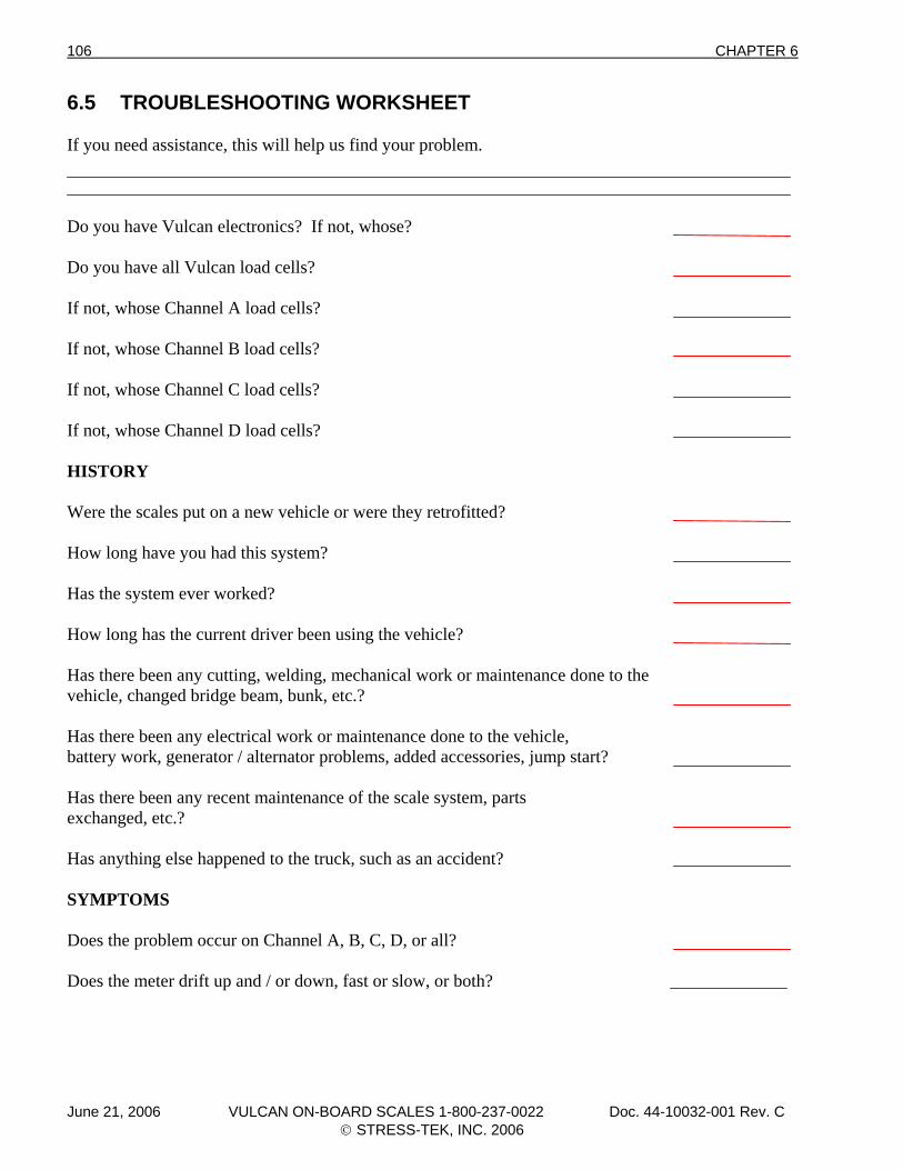
106 CHAPTER 6
6.5 TROUBLESHOOTING WORKSHEET If you need assistance, this will help us find your problem. Do you have Vulcan electronics? If not, whose? Do you have all Vulcan load cells? If not, whose Channel A load cells? If not, whose Channel B load cells? If not, whose Channel C load cells? If not, whose Channel D load cells? HISTORY Were the scales put on a new vehicle or were they retrofitted? How long have you had this system? Has the system ever worked? How long has the current driver been using the vehicle? Has there been any cutting, welding, mechanical work or maintenance done to the vehicle, changed bridge beam, bunk, etc.? Has there been any electrical work or maintenance done to the vehicle, battery work, generator / alternator problems, added accessories, jump start? Has there been any recent maintenance of the scale system, parts exchanged, etc.? Has anything else happened to the truck, such as an accident? SYMPTOMS Does the problem occur on Channel A, B, C, D, or all? Does the meter drift up and / or down, fast or slow, or both?
June 21, 2006 VULCAN ON-BOARD SCALES 1-800-237-0022 Doc. 44-10032-001 Rev. C © STRESS-TEK, INC. 2006
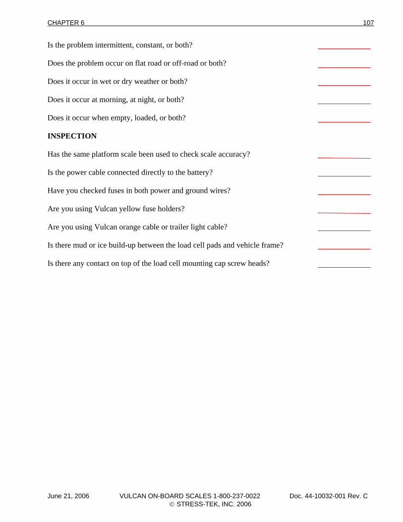
CHAPTER 6 107
Is the problem intermittent, constant, or both? Does the problem occur on flat road or off-road or both? Does it occur in wet or dry weather or both? Does it occur at morning, at night, or both? Does it occur when empty, loaded, or both? INSPECTION Has the same platform scale been used to check scale accuracy? Is the power cable connected directly to the battery? Have you checked fuses in both power and ground wires? Are you using Vulcan yellow fuse holders? Are you using Vulcan orange cable or trailer light cable? Is there mud or ice build-up between the load cell pads and vehicle frame? Is there any contact on top of the load cell mounting cap screw heads?
June 21, 2006 VULCAN ON-BOARD SCALES 1-800-237-0022 Doc. 44-10032-001 Rev. C © STRESS-TEK, INC. 2006
108 CHAPTER 6
6.6 TROUBLESHOOTING ASSISTANCE AND REPLACEMENT PARTS
If you need additional assistance, parts, or service, give us a call at:
VULCAN CUSTOMER SERVICE 1-800-237-0022
HOURS: 7:30 a.m. - 5:00 p.m.
PACIFIC TIME
June 21, 2006 VULCAN ON-BOARD SCALES 1-800-237-0022 Doc. 44-10032-001 Rev. C © STRESS-TEK, INC. 2006
CHAPTER 7 109
C H A P T E R 7 . 0 APPENDIX
June 21, 2006 VULCAN ON-BOARD SCALES 1-800-237-0022 Doc. 44-10032-001 Rev. C © STRESS-TEK, INC. 2006
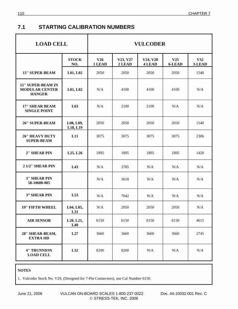
110 CHAPTER 7
7.1 STARTING CALIBRATION NUMBERS
LOAD CELL
VULCODER
STOCK NO.
V26
1 LEAD
V23, V27 2 LEAD
V24, V28 4 LEAD
V25
6-LEAD
V32
3-LEAD
15" SUPER-BEAM
L01, L02
2050
2050
2050
2050
1540
15" SUPER-BEAM IN MODULAR CENTER
HANGER
L01, L02
N/A
4100
4100
4100
N/A
17" SHEAR BEAM
SINGLE POINT
L03
N/A
2100
2100
N/A
N/A
26" SUPER-BEAM
L08, L09, L18, L19
2050
2050
2050
2050
1540
26" HEAVY DUTY
SUPER-BEAM
L11
3075
3075
3075
3075
2306
2" SHEAR PIN
L25, L26
1895
1895
1895
1895
1420
2 1/2" SHEAR PIN
L43
N/A
3785
N/A
N/A
N/A
3" SHEAR PIN
58-10608-005
N/A
3618
N/A
N/A
N/A
3” SHEAR PIN
L53
N/A
7042
N/A
N/A
N/A
19" FIFTH WHEEL
L04, L05,
L31
N/A
2050
2050
2050
N/A
AIR SENSOR
L20, L21,
L40
6150
6150
6150
6150
4615
28" SHEAR-BEAM,
EXTRA HD
L27
3660
3660
3660
3660
2745
4" TRUNNION LOAD CELL
L32
8200
8200
N/A
N/A
N/A
NOTES 1. Vulcoder Stock No. V29, (Designed for 7-Pin Connectors), use Cal Number 6150.
June 21, 2006 VULCAN ON-BOARD SCALES 1-800-237-0022 Doc. 44-10032-001 Rev. C © STRESS-TEK, INC. 2006
CHAPTER 7 111
7.2 SYSTEM SPECIFICATIONS Load Cells Electrical: 350 Ohms nominal impedance. Connector: 4-pin bulkhead, military type. Voltage Required: 5.0 +/- .1 Vdc. Material: High grade alloy steel. Operating Temp: -40 to +140 degrees F. System Accuracy: Typical error less than 1% Full Scale of actual weight for
operating temperature range and normal loading conditions. VSL Vulcoder Environment: Environmentally sealed electronics. Operating Temp.: -40 to +140 degrees F. 4-Wire Cable, Black: Custom, shielded, 4 conductor, polyurethane jacket with drain. 2-Wire Cable, Orange: Custom polyurethane jacket. Connectors: 4-pin, military type. Voltage Input: 10.4 Vdc +/- .2 Vdc. Voltage Output: 5 Vdc +/- .1 Vdc V600 Meter Display: L E D, Variable brightness. Cycle Speed: Variable cycle speed, 1 - 9 seconds. Graduation: 10, 20, 50, 100 or 200 lb or kg Display Range: -99,999 to 999,999 Voltage Required: 10.5 - 29 Vdc. Current Draw: .5 A to 2 A. Protection: Internal fuse & diode protection. Hookup: Screw type, quick release terminal block on rear panel. Operating Temp: -40 to +180 degrees F. Weight: 1.5 lbs. Installation: Power cables, fuses, mounting bracket and thumb screws
provided.
June 21, 2006 VULCAN ON-BOARD SCALES 1-800-237-0022 Doc. 44-10032-001 Rev. C © STRESS-TEK, INC. 2006
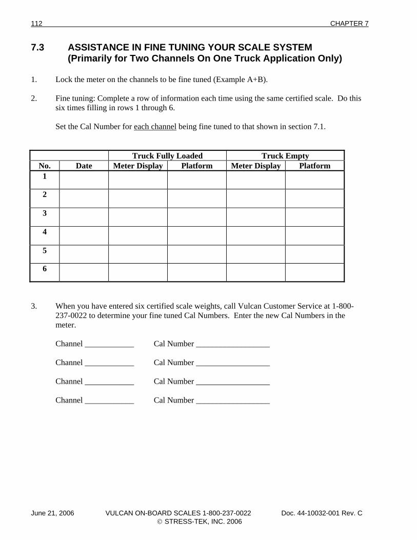
112 CHAPTER 7
7.3 ASSISTANCE IN FINE TUNING YOUR SCALE SYSTEM (Primarily for Two Channels On One Truck Application Only) 1. Lock the meter on the channels to be fine tuned (Example A+B). 2. Fine tuning: Complete a row of information each time using the same certified scale. Do this six times filling in rows 1 through 6. Set the Cal Number for each channel being fine tuned to that shown in section 7.1.
Truck Fully Loaded Truck Empty No. Date Meter Display Platform Meter Display Platform 1
2
3
4
5
6
3. When you have entered six certified scale weights, call Vulcan Customer Service at 1-800- 237-0022 to determine your fine tuned Cal Numbers. Enter the new Cal Numbers in the meter. Channel ____________ Cal Number __________________ Channel ____________ Cal Number __________________ Channel ____________ Cal Number __________________ Channel ____________ Cal Number __________________
June 21, 2006 VULCAN ON-BOARD SCALES 1-800-237-0022 Doc. 44-10032-001 Rev. C © STRESS-TEK, INC. 2006
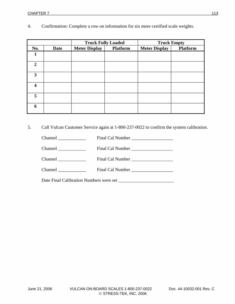
CHAPTER 7 113
4. Confirmation: Complete a row on information for six more certified scale weights.
Truck Fully Loaded Truck Empty No. Date Meter Display Platform Meter Display Platform 1
2
3
4
5
6
5. Call Vulcan Customer Service again at 1-800-237-0022 to confirm the system calibration. Channel ____________ Final Cal Number __________________ Channel ____________ Final Cal Number __________________ Channel ____________ Final Cal Number __________________ Channel ____________ Final Cal Number __________________ Date Final Calibration Numbers were set ________________________
June 21, 2006 VULCAN ON-BOARD SCALES 1-800-237-0022 Doc. 44-10032-001 Rev. C © STRESS-TEK, INC. 2006
114 CHAPTER 7
7.4 KEEPING RECORDS Channel A Channel A Active? Yes No Tare Number ______________ Final Cal Number ______________ Channel B Channel B Active? Yes No Tare Number ______________ Final Cal Number ______________ Channel C Channel C Active? Yes No Tare Number ______________ Final Cal Number ______________ Channel D Channel D Active? Yes No Tare Number ______________ Final Cal Number ______________
June 21, 2006 VULCAN ON-BOARD SCALES 1-800-237-0022 Doc. 44-10032-001 Rev. C © STRESS-TEK, INC. 2006


![VULCAN VIZU HOLDA - Amazon S3...VULCAN CATERING EQUIPMENT (PTY)LTD [ 6 ] VULCAN VIZU HOLDA VULCAN CATERING EQUIPMENT (PTY)LTD VULCAN VIZU HOLDA WIRING DIAGRAM Item No. Stores Ref.No](https://img.pdfslide.net/doc/110x75/60e756b4cf711d2301079486/vulcan-vizu-holda-amazon-s3-vulcan-catering-equipment-ptyltd-6-vulcan.jpg)
![VULCAN HIGH SPEED DEEP FAT FRYER (ELECTRIC) › vulcan-website...Vulcan catering equipment (ptY)ltD [ 2 ] VULCAN HIGH SPEED DEEP FAT FRYER (ELECTRIC) GENERAL DATA: MANUFACTURER: Vulcan](https://img.pdfslide.net/doc/110x75/60c05ae5c355355f26327394/vulcan-high-speed-deep-fat-fryer-electric-a-vulcan-website-vulcan-catering.jpg)