Embed Size (px)
Citation preview
02-01-15
23 21 11 - 1
SECTION 23 21 11 BOILER PLANT PIPING SYSTEMS
SPEC WRITER NOTES: 1. Delete between //----// if not
applicable to project. Also delete any other item or paragraph not applicable to the project and renumber the paragraphs.
2. References to pressure in this section are gage pressure unless otherwise noted.
PART 1 – GENERAL:
1.1 DESCRIPTION:
All boiler plant piping systems, except plumbing and sanitary,
including piping supports. Piping located outside of the boiler plant
building is not included except for gas regulator and meter stations.
1.2 RELATED WORK:
A. Section 01 33 23, SHOP DRAWINGS, PRODUCT DATA, and SAMPLES.
B. Section 22 11 00 FACILITY WATER DISTRIBUTION.
G. Section 22 31 11, WATER SOFTENERS.
B. Section 23 05 10, COMMON WORK RESULTS FOR Boiler Plant and STEAM
GENERATION
C. Section 23 05 51, NOISE and VIBRATION CONTROL FOR BOILER PLANT.
D. Section 23 07 11, HVAC and BOILER PLANT INSULATION.
E. Section 23 08 00, COMMISSIONING OF HVAC SYSTEMS.
F. Section 23 09 11, INSTRUMENTATION and CONTROL FOR BOILER PLANT.
H. Section 23 50 11, BOILER PLANT MECHANICAL EQUIPMENT.
I. Section 23 52 33, WATER-TUBE BOILERS.
J. Section 23 52 39, FIRE-TUBE BOILERS.
1.3 QUALITY ASSURANCE:
A. Entire installation shall comply with ASME Power Piping Code, ASME
B31.1 and appendices.
B. Boiler External Piping, as defined in the ASME Boiler and Pressure
Vessel Code, Section I, is required to be constructed and inspected in
conformance with the ASME Code.
C. Mechanics shall be skilled in their work or trade. Welders on pressure
vessels or piping shall show evidence of qualification in accordance
with the ASME Power Piping Code and the ASME Boiler and Pressure Vessel
Code. Certify that each welder has passed American Welding Society
(AWS) qualification tests for the welding processes involved, and that
certification is current. Each welder shall utilize a stamp to identify
02-01-15
23 21 11 - 2
all work performed by the welder. The Government reserves the right to
reject any personnel found unqualified in the performance of work for
which they are employed.
1.4 SUBMITTALS:
A. Submit in accordance with Section 01 33 23, SHOP DRAWINGS, PRODUCT
DATA, and SAMPLES.
B. Piping:
1. ASTM material specification number.
2. Grade, class or type, schedule number.
3. Manufacturer.
C. Pipe Fittings, Unions, Flanges:
1. ASTM material specification number.
2. ASME standards number.
3. Catalog cuts.
4. Pressure and temperature ratings.
D. Valves - Gate, Globe, Check, Plug, Butterfly, Ball:
1. Catalog cuts showing design and construction.
2. Pressure and temperature ratings.
3. Materials of construction.
4. Accessories.
E. Sight flow indicators:
1. Catalog cuts showing design and construction.
2. Pressure and temperature ratings.
3. Materials of construction.
F. Quick-Couple Hose Connectors and Steam Hose:
1. Catalog cuts showing design and construction.
2. Pressure and temperature ratings.
3. Materials of construction.
4. Type of seal between couplings.
5. Flexibility of steam hose.
G. Pressure Reducing and Regulating Valves, Back Pressure Relief Valves,
Safety Valves, Relief Valves:
1. Catalog cuts showing design and construction.
2. Service limitations (type of fluid, maximum pressure and
temperatures).
3. Materials of construction.
4. Flow capacity at required set pressure.
02-01-15
23 21 11 - 3
5. Predicted sound levels, at operating condition, for steam pressure
reducing valves.
H. Strainers:
1. Catalog cuts showing design and construction.
2. Pressure and temperature ratings.
3. Materials of construction.
4. Strainer basket or liner mesh.
5. Pressure loss and flow rate data.
I. Emergency Gas Safety Shutoff Valves, Automatic Earthquake Gas Valves:
1. Catalog cuts showing design and construction.
2. Maximum pressure rating.
3. Material of construction.
4. Pressure loss and flow rate data.
J. Steam Traps:
1. Catalog cuts showing design and construction.
2. Service limitations (maximum pressures and temperatures).
3. Materials of construction.
4. Flow rates at differential pressures shown on drawings.
5. Orifice size for each trap.
K. Flexible Connectors:
1. Catalog cuts showing design and construction.
2. Pressure and temperature ratings.
3. Materials of construction.
4. Maximum allowable lateral and axial movements.
5. Description of type of movement permitted, intermittent offset or
continuous vibration.
L. Pipe Support Systems:
1. Credentials of technical personnel who will design the support
systems.
2. Validation of computer program for pipe support selection.
3. Input and output data for pipe support selection program for all
piping systems with pipe sizes 60 mm (2-1/2 inches) and above.
4. Boiler and feedwater deaerator steam nozzle (pipe connection)
allowable and actual forces and moments imposed by connecting
piping.
5. Hanger load calculation methods and results for piping systems with
pipe sizes 50 mm (2 inches) and below.
6. Piping layouts showing location and type of each hanger and support.
02-01-15
23 21 11 - 4
7. Catalog cuts showing design and construction of each hanger and
support and conformance of hangers and supports to MSS standards.
8. Drawings showing arrangement and sizes of all components comprising
each spring-type hanger and support assembly.
9. Load rating and movement tables for all spring hangers, and seismic
shock absorbing devices.
10. Stress analyses on the boiler plant piping systems under all
possible load conditions as part of the design. Once all piping is
completed another stress analysis is required on the as built
systems.
1.5 PRODUCT DELIVERY, STORAGE AND HANDLING:
All piping shall be stored and kept free of foreign material and shall
be internally and externally cleaned of all oil, dirt, rust and foreign
material. Deliver and store valves and pipe hangers in sealed shipping
containers with labeling in place. Storage must be in dry, protected
location.
SPEC WRITER NOTE: Fill blank spaces within this paragraph. Specification is based on high pressure saturated steam, 110 to 1025 kPa (16 - 150 psi), main header pressure in the boiler plant. The entire specification must be revised if header pressures are significantly lower or higher.
1.6 INFORMATION ON PRESSURE-TEMPERATURE DESIGN OF PIPING SYSTEMS:
A. Steam service pressures are selected to provide optimum pressure to the
facilities served by the boiler plant. Main steam header pressure shall
be controlled at ____kPa (____psi). Maximum pressure capability of
steam systems between boilers and through first pressure reducing valve
protected by a safety valve shall be governed by the
pressure/temperature relationship of the highest safety valve setting
shown for the boilers.
B. Steam distribution systems protected by safety valves following
pressure reducing stations or protected by safety valves on the boilers
shall be governed by the pressure/temperature relationship developed by
the maximum setting of the safety valve on that system.
C. Boiler feedwater systems between boiler feed pumps, economizers (if
provided), and boilers are designed for a normal maximum temperature of
138 °C (280 °F), and emergency temperature of 213 °C (415 °F) (if
economizers are provided and economizer safety relief valve setting is
02-01-15
23 21 11 - 5
1896 kPa (275 psi)). Design pressure is the greater of: boiler feed
pump shut off head; or 1896 kPa (275 psi) set pressure, plus
accumulation, of economizer (if provided) relief valve.
D. Condensate collection and transfer systems to suction of boiler feed
pumps are designed for maximum temperatures to 100 °C (212 °F), and
pressures 276 kPa (40 psi). Vacuum return systems shall operate between
0 and 27 kPa (0 and 8 inch Hg) vacuum and equivalent steam saturation
temperatures.
SPEC WRITER NOTE: Add pressure information on propane/air system if system is provided.
E. Natural gas fuel systems are designed and materials and equipment are
applied to prevent failure under gas pressure of ____kPa (____ psi)
entering Government property. LP gas systems for igniters (pilots) are
designed for maximum LP tank pressure of 1725 kPa (250 psig).
F. Fuel oil system pressures are determined by the requirements of the
burners and fuel trains. No. 2 oil systems are designed for maximum
temperatures of 55 °C (130 °F), and pressures of 1025 kPa (150 psi). No.
5 or 6 oil systems are designed for 120 °C (250 °F), and 1025 kPa (150
psi).
G. Water service pressures are ____ kPa (____psi) maximum. Systems are
designed to operate under conditions of maximum available pressure.
H. Drips, drains, blowdown, water sampling, and chemical treatment are
designed, and materials and equipment are applied in accordance with
the maximum pressure and temperature of the system with which they are
associated.
I. Low pressure steam, condensate, vacuum and vents are designed for
service pressures and temperatures equivalent to 103 kPa (15 psi)
saturated steam.
J. Compressed air systems are designed to accommodate a maximum pressure
of 850 kPa (125 psi).
K. Instrumentation and control piping shall be provided for the service
and pressure characteristics of the systems to which they are
connected.
1.7 APPLICABLE PUBLICATIONS:
A. The publications listed below form a part of this specification to the
extent referenced. The publications are referenced in the text by the
basic designation only.
02-01-15
23 21 11 - 6
B. ASTM International (ASTM):
A47/A47M-99(2009).......Standard Specification for Ferritic Malleable
Iron Castings
A48/A48M-03(2008).......Standard Specification for Gray Iron Castings
A53/A53M-10.............Standard Specification for Pipe, Steel, Black
and Hot-Dipped, Zinc-Coated, Welded and
Seamless
A105/A105M-10...........Standard Specification for Carbon Steel
Forgings for Piping Applications
A106/A106M-10...........Standard Specification for Seamless Carbon
Steel Pipe For High Temperature Service
A126-04(2009)...........Standard Specification for Gray Iron Castings
for Valves, Flanges and Pipe Fittings
A193/A193M-10...........Standard Specification for Alloy-Steel and
Stainless Steel Bolting Materials for High
Temperature Service
A194/A194M-10...........Standard Specification for Carbon and Alloy
Steel Nuts for Bolts for High-Pressure or High-
Temperature Service, or Both
A197/A197M-00(2006).....Standard Specification for Cupola Malleable
Iron
A216/A216M-08...........Standard Specification for Steel Castings,
Carbon, Suitable for Fusion Welding, For High
Temperature Service
A234/A234M-10...........Standard Specification for Piping Fittings of
Wrought Carbon Steel and Alloy Steel for
Moderate and High Temperature Service
A269-10.................Standard Specification for Seamless and Welded
Austenitic Stainless Steel Tubing for General
Service
A395/A395M-99(2009).....Standard Specification for Ferritic Ductile
Iron Pressure-Retaining Castings for use at
Elevated Temperatures
A536-84(2009)...........Standard Specification for Ductile Iron
Castings
B61-08..................Standard Specification for Steam or Valve
Bronze Castings
02-01-15
23 21 11 - 7
B62-09..................Standard Specification for Composition Bronze
or Ounce metal Castings
B88/B88M-09.............Standard Specification for Seamless Copper
Water Tube
C. American Society of Mechanical Engineers (ASME):
Boiler and Pressure Vessel Code: 20072010 Edition with current Addenda
Section I...............Power Boilers
Section IX..............Welding and Brazing Qualifications
B16.3-2006..............Malleable Iron Threaded Fittings
B16.4-2006..............Gray Iron Threaded Fittings
B16.5-2009..............Pipe Flanges and Flanged Fittings: NPS ½
Through 24
B16.9-2007..............Factory Made Wrought Buttwelding Fittings
B16.11-2009.............Forged Fittings, Socket-Welding and Threaded
B16.22-2001.............Wrought Copper and Copper Alloy Solder Joint
Pressure Fittings
B31.1-2010..............Power Piping
D. Manufacturers Standardization Society of the Valve and Fittings
Industry (MSS):
SP-45-03(2008)..........Bypass and Drain Connections
SP-58-2009..............Pipe Hangers and Supports-Materials, Design,
Manufacture, Selection, Application, and
Installation
SP-69-2003..............Pipe Hangers and Supports-Selection and
Application
SP-80-2008..............Bronze, Gate, Globe, Angle and Check Valves
SP-89-2003..............Pipe Hangers and Supports-Fabrication and
Installation Practices
SP-90-2000..............Guidelines on Terminology for Pipe Hangers and
Supports
SP-97-2006..............Integrally Reinforced Forged Branch Outlet
Fittings – Socket Welding, Threaded and
Buttwelding Ends
SP-127-2001.............Bracing for Piping Systems Seismic – Wind –
Dynamic Design, Selection, Application
E. National Fire Protection Association (NFPA):
30-2008.................Flammable and Combustible Liquids Code
02-01-15
23 21 11 - 8
31-2011.................Standard for the Installation of Oil Burning
Equipment
F. American Welding Society (AWS):
B2.1-2009...............Specification for Welding Procedure and
Performance Qualification
G. Pipe Fabrication Institute (PFI):
PFI ES-24-08............Pipe Bending Methods, Tolerances, Process and
Material Requirements
PART 2 – PRODUCTS:
SPEC WRITER NOTE: Make material requirements agree with applicable requirements specified in the referenced Applicable Publications. Update and specify only that which applies to the project.
2.1 STEAM PIPING:
A. Pipe: Carbon steel, ASTM A53 Grade B or ASTM A106 Grade B, seamless or
electric resistance welded (ERW). Schedule 40 for piping //up to 862
kPa (125 psig)// with welded ends, Schedule 80 for piping with threaded
ends //and piping over 862 kPa (125 psig) with welded ends.//Standard
weight permitted for pipe sizes 300 mm (12 inches) and above.//
B. Joints:
1. Pipe sizes 65 mm (2-1/2 inches) and above: Butt-welded
2. Pipe sizes 50 mm (2 inches) and below: Threaded, butt-welded, or
socket-welded.
C. Fittings:
1. Welded joints: Steel, ASTM A234, Grade B, ASME B16.9, same schedule
as adjoining pipe, all elbows long radius.
2. Threaded joints: Forged steel, ASME B16.ll, 13,790 kPa (2000 psi
class; or malleable iron, ASTM A47 or A197, ASME B16.3, 2050 kPa
(300 psi) class.
3. Socket-welded joints: Forged steel, ASME B16.11, 13,790 kPa (2000
psi) class.
D. Unions on Threaded Piping: Forged steel, 13,800 kPa (2000 psi) class or
20,680 kPa (3000 psi) class; or malleable iron, 2050 kPa (300 psi) on
piping 50 mm (2 inches) and under.
E. Flanges and Bolts: Forged steel weld neck, ASME B16.5, ASTM A105, 1025
kPa (150 psi) pressure class, except 2050 kPa (300 psi) class required
adjacent to 1725 kPa (250 psi) and 2050 kPa (300 psi) class valves.
02-01-15
23 21 11 - 9
Bolts shall be high strength steel ASTM A193, Class 2, Grade B8. Nuts
shall be ASTM A194.
2.2 STEAM CONDENSATE PIPING:
A. Includes all gravity, drip return, pumped and vacuum systems. Does not
include piping system between boiler feed pumps and boilers.
B. Pipe: Carbon steel, ASTM A53 Grade B or ASTM A106 Grade B, seamless or
ERW, Schedule 80.
C. Joints:
1. Pipe sizes 65 mm (2-l/2 inches) and above: Butt-welded.
2. Pipe sizes 50 mm (2 inches) and below: Threaded, butt-welded or
socket-welded.
D. Fittings:
1. Welded joints: Steel, ASTM A234, Grade B, ASME B16.9, same schedule
as adjoining pipe.
2. Threaded joints: Forged steel, ASME B16.ll, 13,790 kPa (2000 psi
class; or malleable iron, ASTM A47 or A197, ASME B16.3, 2050 kPa
(300 psi) class.
3. Socket-welded joints: Forged steel, ASME B16.11, 13,800 kPa (2000
psi) class.
E. Unions on Threaded Piping: Forged steel, 13,800 kPa (2000 psi) class or
20,680 kPa (3000 psi) class; or malleable iron, 2050 kPa (30 psi). On
piping 50 mm (2 inches) and under.
F. Flanges: Forged steel weld neck, ASTM A105, ASME B16.5, 1025 kPa (150
psi).
2.3 FUEL PIPING:
A. Natural gas, LP gas (propane), fuel oil (No. 2, or Nos. 5 or 6 heated)
for main burner and igniter (pilot) fuels, gas vent piping. Comply
with ASME B3l.l.
B. Piping: Carbon steel, ASTM A53 Grade B or ASTM A106 Grade B, seamless
or ERW, Schedule 40. Fuel oil piping shall be seamless downstream of
burner automatic shutoff valves.
C. Joints:
1. Pipe sizes 65 mm (2-l/2 inches) and above: Butt-welded.
2. Pipe sizes 50 mm (2 inches) and below: Socket-welded or butt-welded.
D. Fittings:
1. Butt-welded joints: Steel, ASTM A234, Grade B, ASME B16.9, same
schedule as adjoining pipe.
02-01-15
23 21 11 - 10
2. Socket-welded joints: Forged steel, ASME B16.ll, 13,790 kPa (2000
psi class.
E. Unions on piping 50 mm (2 inches) and under: Forged steel, 13,800 kPa
(2000 psi) class or 20,680 kPa (3000 psi) class.
F. Flanges: Forged steel weld neck, ASME B16.5, ASTM A105, 1025 kPa (150
psi).
G. Companion flanges: Flanges and bolting shall conform to ASME B16.5.
H. Burner Piping: Furnished as part of the factory-assembled burners may
be manufacturer's standard materials and assembly. Comply with ASME
B3l.l, for the actual operating conditions.
I. Igniter (Pilot) Piping: Furnished as part of the factory assembled
burners may have 2050 kPa (300 psi) ASTM A47, ASME B16.3 malleable iron
threaded fittings in lieu of welded steel. If threaded fittings are
provided, piping shall be Schedule 80.
2.4 BOILER FEEDWATER PIPING:
A. Piping from boiler feedwater pump discharge to inlet of boilers.
B. Pipe: Carbon steel, ASTM A53 Grade B or ASTM A106 Grade B, seamless or
ERW. Piping with threaded joints shall be Schedule 80; welded joints
Schedule 40.
C. Joints:
1. Pipe sizes 65 mm (2-1/2 inches) and above: Butt-welded.
2. Pipe sizes 50 mm (two inches) and below: Threaded, butt-welded, or
socket-welded.
D. Fittings:
1. Butt-welded Joints: Steel, ASTM A234, Grade B, ASME B16.9, same
schedule as adjoining pipe.
2. Threaded Joints: Forged steel, ASME B16.ll, 13,790 kPa (2000 psi
class; or malleable iron, ASTM A47, ASME B16.3, 2050 kPa (300 psi)
class.
3. Socket-welded joints: Forged steel, ASME B16.11, 13,800 kPa (2000
psi) class.
E. Unions: Forged steel, 13,800 kPa (2000 psi) class or 20,680 kPa (3000
psi) class; or malleable or ductile iron, 2050 kPa (300 psi) class.
F. Flanges and Bolts: Forged steel weld neck, ASME B16.5, ASTM A105, 2050
kPa (300 psi) pressure class. Bolts shall be High strength ASTM A193,
Class 2, Grade B8. Nuts shall be ASTM A194.
02-01-15
23 21 11 - 11
2.5 BOILER BLOWOFF PIPING:
A. From boiler bottom blowoff connection to blowoff tank. Connections
between boiler accessories drain valves and blowoff lines.
B. Pipe: Carbon steel, ASTM A106, Grade B, seamless, Schedule 80.
C. Joints: Butt-welded.
D. Fittings: Steel, ASTM A234, Grade B, ASME B16.9, same schedule as
adjoining pipe, all elbows long radius, no tees or crosses permitted.
E. Flanges: Forged steel weld neck, ASME B16.5, ASTM A105, 2050 kPa (300
psi).
F. At no point shall the bottom blow down lines raise above the point of
connection to the boiler.
2.6 DRAIN PIPING FROM BOILER ACCESSORIES TO DRAIN VALVE:
A. Drain piping from water column, low water cutoffs, gage glass, water
level sensor, remote water level devices (where applied).
B. Pipe: Carbon steel, ASTM A106, seamless, Schedule 40.
C. Joints: Threaded.
D. Fittings: Forged steel, ASME B16.ll, 13,790 kPa (2000 psi class); or
malleable iron, ASTM A47 or A197, ASME B16.3, 2050 kPa (300 psi) class.
E. Unions: Forged steel, 13,800 kPa (2000 psi) class or 20,680 kPa (3000
psi) class; or malleable iron, 2050 kPa (300 psi) class.
2.7 VENT LINES FROM TANKS AND SAFETY AND RELIEF VALVES:
A. Pipe: Carbon steel, ASTM A53 Grade B or A106 Grade B, seamless or ERW,
Schedule 40.
B. Joints:
1. Pipe sizes 65 mm (2-l/2 inches) and above: Butt-welded.
2. Pipe sizes 50 mm (2 inches) and below: Threaded or butt-welded.
C. Fittings:
1. Welded Joints: Steel, ASTM A234 Grade B, ASME B16.9, same schedule
as adjoining pipe.
2. Threaded Joints: Cast iron, ASME B16.4, 850 kPa (125 psi).
D. Unions: Forged steel, 13,800 kPa (2000 psi) class or 20,680 kPa (3000
psi) class; or malleable iron, 1025 kPa (150 psi) class.
E. Flanges: Forged steel weld neck, ASME B16.5, ASTM A105, 1025 kPa (150
psi).
2.8 COLD WATER PIPING:
A. Soft Water: See Section 22 31 11, WATER SOFTENERS.
B. City Water: See Section 22 11 00, FACILITY WATER DISTRIBUTION.
C. All copper pipe shall use only soldered fittings.
02-01-15
23 21 11 - 12
2.9 COMPRESSED AIR PIPING (FUEL OIL ATOMIZING SERVICE):
A. Pipe: Carbon steel, ASTM A53 Grade B or ASTM A106 Grade B, seamless or
ERW Schedule 40.
B. Joints: Threaded.
C. Fittings: Forged steel, ASME B16.ll, 13,790 kPa (2000 psi class); or
malleable iron ASTM A47 or A197, ASME Bl6.3, 1025 kPa (150 psi) class.
D. Unions: Forged steel, 13,800 kPa (2000 psi) class or 20,680 kPa (3000
psi) class; or malleable iron, 1025 kPa (150 psi) class.
SPEC WRITER NOTE: If No. 5 or No. 6 fuel oil will be burned, specify steel draft gage piping with crosses at all direction changes.
//2.10 COMPRESSED AIR AND BOILER DRAFT GAGE PIPING (PNEUMATIC CONTROL AND INSTRUMENTATION):
A. Air drier to utilization point; draft gage sensing lines.
B. Copper tubing, hard drawn, ASTM B88, Type L.
C. Fittings: Wrought copper, ASME B16.22, soldered.
D. Draft Gage Piping: 6 mm (1/4 inch) pipe size minimum.//
2.11 BOILER WATER SAMPLING, CONTINUOUS BLOWDOWN:
A. Pipe: Steel, ASTM A106 Grade B, seamless, Schedule 80.
B. Joints: Threaded.
C. Fittings: Forged steel, ASME B16.ll, 13,790 kPa (2000 psi class); or
malleable iron, ASTM A47 or A197, ASME B16.3, 2050 kPa (300 psi) class.
Fittings between boiler and first stop valve must be forged steel, ASME
B16.11, 13,790 kPa (2000 psi) or 20,700 kPa (3000 psi) class.
D. Unions: Malleable iron, 2050 kPa (300 psi) class.
2.12 FEEDWATER SAMPLING AND CHEMICAL FEED PIPING:
A. Pipe: Stainless steel tubing, ASTM A269, Type 316.
B. Fittings: Stainless steel Type 316 welding fittings.
2.13 MISCELLANEOUS PIPING:
A. Instrument and Control Piping (Sensing Point to Transmitter,
Controller, or Other Instrument): Construction shall be same as
specified for main service.
B. Drain Piping (All Drain Piping Discharging to Floor Drain-From Drain
Valve to Floor Drain):
1. Pipe: Carbon steel, ASTM A53 Grade B or ASTM A106 Grade B, seamless
or ERW, Schedule 40.
2. Fittings and Unions: Forged steel, ASME B16.ll, 13,790 kPa (2000 psi
class); or malleable iron, 1025 kPa (150 psi), threaded.
02-01-15
23 21 11 - 13
C. Pump Recirculation:
1. Pipe: Carbon steel, ASTM A53 Grade B or ASTM A106 Grade B, seamless
or ERW, double extra strong. Schedule 40 permitted on all lines 1500
mm (5 feet) or more from the recirculation orifice.
2. Joints: Threaded.
3. Fittings: Forged steel, ASME B16.ll, 13,790 kPa (2000 psi class); or
malleable iron, ASTM A47 or A197, ASME B16.3, 2050 kPa (300 psi)
class, except 1025 kPa (150 psi) class permitted on all lines 1500
mm (5 feet) or more from the recirculation orifice.
4. Unions: Forged steel, 13,800 kPa (2000 psi) class or 20,680 kPa
(3000 psi) class; or malleable iron, ASTM A47 or A197, same pressure
class as nearest fittings.
2.14 DIELECTRIC FITTINGS:
Provide threaded dielectric unions for pipe sizes 50 mm (2 inches) and
under. For 65 mm (2-1/2 inches) and above, provide copper and steel
flanges electrically isolated at gasket and by sleeves at bolts.
Fittings on cold water and soft water lines shall be rated for 690 kPa
(100 psi), 27 °C (80 °F). Fittings on steam condensate lines shall be
rated at 510 kPa (75 psi), 120 °C (250 °F). Fittings on other services
shall be rated for the maximum pressure and temperature conditions of
the service.
2.15 VALVES; GATE, GLOBE, PLUG, CHECK, BALL, BUTTERFLY, VENT COCKS:
A. Valves for particular services are generally specified as Type Numbers.
The Type Numbers are defined below. All valves of the same type shall
be the products of a single manufacturer. Comply with MSS SP-45, MSS
SP-80, and ASME B3l.l. Design valves for the service fluids and
conditions. Pressure-temperature ratings listed are minimum
requirements. Packing and gaskets shall not contain asbestos.
B. Valve Type Designations:
1. Gate Valves:
a. Type 101: Cast steel body ASTM A2l6 WCB, rated for 1025 kPa at
260 °C (150 psi at 500 °F), ll-l/2 to l3 percent chromium
stainless steel flexible wedge and hard faced (stellite) or
nickel copper alloy seats, 1025 kPa (150 psi) ASME flanged ends,
OS&Y, rising stem, bolted bonnet.
1) Provide factory installed globe-valved warm-up bypass when
main valve is 75 mm (3 inch) pipe size or greater and serves
steam main longer than 6 m (20 feet). Conform to MSS SP-45.
02-01-15
23 21 11 - 14
2) Drill and tap bosses for connection of drains. Conform to MSS
SP-45.
b. Type l02: Cast iron body ASTM Al26 Class B, rated for 1725 kPa
(250 psi) saturated steam, 3440 kPa (500 psi) WOG, bronze wedge
and seats, 1725 kPa (250 psi) ASME flanged ends, OS&Y, rising
stem, bolted bonnet, renewable seat rings.
1) Provide factory installed globe-valved bypass when main valve
is 75 mm (3 inch) pipe size or greater and serves steam main
longer than 6 m (20 feet). Conform to MSS SP-45.
2) Drill and tap bosses for connection of drains if valve is in
steam service. Conform to MSS SP-45.
c. Type 103: Cast iron body ASTM Al26 Class B, rated for 850 kPa
(125 psi) saturated steam, 1375 kPa (200 psi) WOG, bronze or
bronze faced wedge and seats, 850 kPa (125 psi) ASME flanged
ends, OS&Y, rising stem, bolted bonnet, renewable seat rings.
1) Provide factory installed globe-valved bypass when main valve
is 75 mm (3 inch) pipe size or greater and serves steam main
longer than 6 m (20 feet). Conform to MSS SP-45.
2) Drill and tap bosses for connection of drains if valve is in
steam service. Conform to MSS SP-45.
d. Type 104: Bronze body ASTM B6l, rated for 1375 kPa (200 psi)
saturated steam, 2750 kPa (400 psi) WOG, bronze wedges and Monel
or stainless steel seats, threaded ends, rising stem, union
bonnet.
e. Type l05: Forged steel body ASTM A105, rated for 2050 kPa at 216
°C (300 psi at 420 °F) minimum, Class 4130 kPa (600 psi) or Class
5500 kPa (800 psi), hardened stainless steel or stellite wedge
and seats, threaded ends, OS&Y, rising stem, bolted bonnet.
2. Globe Valves:
a. Type 201: Cast steel body ASTM A216 WCB, rated for 1025 kPa at
260 °C (150 psi at 500 °F), 11-1/2 to 13 percent chromium
stainless steel or stellite disc and seat, 1025 kPa (150 psi)
ASME flanged ends, OS&Y, rising stem, bolted bonnet, renewable
seat rings. Drill and tap bosses for connection of drains where
shown. Conform to MSS SP-45.
b. Type 202: Cast iron body ASTM A126 Class B, rated for 1725 kPa
(250 psi) saturated steam, 3440 kPa (500 psi) WOG, bronze or
bronze faced disc and seat, 1725 kPa (250 psi) ASME flanged ends,
02-01-15
23 21 11 - 15
OS&Y, rising stem, bolted bonnet, renewable seat rings. Drill and
tap bosses for connection of drains where shown. Conform to MSS
SP-45.
c. Type 203: Cast iron body ASTM A126 Class B, rated for 850 kPa
(125 psi) saturated steam, 1375 kPa (200 psi) WOG, bronze or
bronze-faced disc (Teflon or composition facing permitted) and
seat, 850 kPa (125 psi) ASME flanged ends, OS&Y, rising stem,
bolted bonnet, renewable seat rings.
d. Type 204: Bronze body ASTM B6l, rated for 1375 kPa (200 psi)
saturated steam, 2750 kPa (400 psi) WOG, hardened stainless steel
disc and seat, threaded ends, rising stem, union bonnet,
renewable seat rings.
e. Type 205: Forged steel body ASTM A105, rated for 2050 kPa at 216
°C (300 psi at 420 °F) minimum, Class 4130 kPa (600 psi) or Class
5500 kPa (800 psi), stainless steel disc, stellite seat, threaded
ends, OS&Y, rising stem, bolted bonnet.
3. Plug Valves: Cast iron body ASTM Al26 Class B, rated for 1200 kPa
(l75 psi) WOG, one-fourth turn to open. 850 kPa (125 psi) ASME
flanged ends for pipe sizes above 50 mm (2 inches), threaded ends
for pipe sizes 50 mm (2 inches) and under. All components designed
for service to which applied: natural gas, LP gas (propane), or fuel
oil. Furnish lever handle for each valve.
a. Type 301: Two-way valves up through 100 mm (4 inches) pipe size.
Eccentric action, non-lubricated plug with resilient seal molded
into groove on plug face providing bubble-tight shut off. O-ring
stem seal, corrosion-resistant bearings, corrosion-resistant seat
coating, seal materials as recommended by valve manufacturer for
the service. Valves on natural gas service AGA approved.
b. Type 302: Two-way valves 125 mm (5 inches) pipe size and above,
all sizes of three way valves. Lubricated full-port plug type
with lubricant for intended service. Reinforced Teflon stem seal,
valve plug floated on Teflon surfaces, lubricant injection system
that has sufficient pressure to fully lubricate all sealing
surfaces. Provide laminated plastic label attached to each valve
stating, “Lubricate with (Insert appropriate description) once a
year”.
4. Check Valves:
a. Type 401: Not used.
02-01-15
23 21 11 - 16
b. Type 402: Swing-type, cast iron body ASTM A126 Class B, rated for
1725 kPa (250 psi) saturated steam, 3440 kPa (500 psi) WOG,
bronze or bronze-faced disc and seat, 1725 kPa (250 psi) ASME
flanged ends, bolted cover, renewable disc and seat.
c. Type 403: Swing-type, cast iron body ASTM Al26 Class B, rated for
850 kPa (l25 psi) saturated steam, 1375 kPa (200 psi) WOG, bronze
or bronze-faced disc and seat, 850 kPa (l25 psi) ASME flanged
ends, bolted cover, renewable disc and seat.
d. Type 404: Swing-type, bronze body ASTM B61, rated for 1375 kPa
(200 psi) saturated steam, 2750 kPa (400 psi) WOG, bronze disc,
threaded ends, regrinding disc.
e. Type 405: Lift-type, forged steel body ASTM A105, rated for 2050
kPa at 216 °C (300 psi at 420 °F) minimum (Class 4130 kPa (600
psi) or 5500 kPa (800 psi)), hardened stainless steel disc, hard
faced seat, bolted cover, threaded ends.
f. Type 406: Swing-type, Type 316 stainless steel body, disc and
hanger, rated for 1725 kPa at 182 °C (250 psi at 360 °F) minimum.
g. Type 407: Silent spring-loaded wafer type, cast iron body ASTM
A48 or A126 Class B, rated for 850 kPa (125 psi) water, 121 °C
(250 °F).
h. Type 408: Silent spring-loaded wafer type, cast steel ASTM A216
WCB or cast iron ASTM A48 or A126 body, rated for 2050 kPa (300
psi) water, 121 °C (250 °F), stainless steel trim.
5. Ball Valves: Reduced port permitted for bypass (throttling) service;
full port required for all other services, one-fourth turn to open.
a. Type 501: Type 316 stainless steel body, ball and stem, rated for
1025 kPa at 185 °C (150 psi at 365 °F), 4130 kPa at 93 °C (600 psi
at 200 °F); reinforced TFE seat, stem seal and thrust washer; end
entry, threaded ends.
b. Type 502: Bronze body, rated for 1025 kPa at 185 °C (150 psi at
365 °F), 1725 kPa at 121 °C (250 psi at 250 °F), reinforced TFE
seat, stem seal and thrust washer; end entry, threaded ends, UL-
listed for natural or LP gas shut off service when used on those
services.
c. Type 503: Carbon steel or ASTM B61 bronze body, steam service,
rated for 1380 kPa at 200 °C (200 psi at 390 °F), stainless steel
02-01-15
23 21 11 - 17
ball and stem, Polyfil seat, live-loaded or adjustable stem seal,
threaded ends.
d. Type 504: Carbon steel or ASTM A536 ductile iron body, saturated
steam service, rated for 1030 kPa (150 psi), stainless steel ball
and stem, Polyfil seat, live-loaded stem seal, ASME flanged ends.
6. Butterfly Valves:
a. Type 601: Ductile iron body ASTM A395 or A536, wafer style, rated
for 850 kPa at 120 °C (125 psi at 250 °F), bronze disc, stainless
steel stem, EPDM liner, EPDM stem seal and body seal, neck
extending beyond pipe insulation, lever operator.
b. Type 602: Carbon steel body, triple-offset design, lug or flanged
type, rated for steam service at 1025 kPa at 260 °C (150 psi at
500 °F), stainless steel nitrided disc, stainless steel seat,
stainless steel shaft, stainless steel/graphite laminated seal
ring, neck extending beyond pipe insulation, geared handwheel
operator for valves 100 mm (4 inch) pipe size and over, lever
operator for valves 75 mm (3 inch) pipe size and under.
7. Gas Vent Cocks:
a. Type 701: Bronze body, tee handle, rated for 205 kPa at 38 °C (30
psi at 100 °F), ground plug, rated for tight shut-off on fuel gas
service.
C. Boiler Valves:
1. Steam Non-Return Stop Check Valves:
a. Type: Straight-way Y-pattern, with dash-pot and piston and tapped
drain openings, OS&Y, bolted bonnet, rising stem. Provide angle
pattern only if shown on the contract drawings.
SPEC WRITER NOTE: Cast iron versions of these valves are available. Reports from boiler inspectors are that the cast iron valves are subject to failures due to the high forces and moments in the piping system.
b. Construction: Cast steel body ASTM A216 WCB, rated for 2050 kPa
(300 psi) saturated steam, stellite faced steel disc, alloy steel
seat, 2050 kPa (300 psi) ASME flanged ends.
02-01-15
23 21 11 - 18
c. Operation: Valves shall automatically close tightly when boiler
steam pressure becomes less than that of the steam header. Valves
shall operate without sticking or chattering.
2. Stop Valves for Soot Blower, Steam Vents on Boiler Drums and Steam
Lead, Steam Pressure Gage:
a. Installation of steam pressure gage shut-off valves shall conform
to ASME Boiler and Pressure Vessel Code, Section I.
b. Soot blower angle stop valves (water tube boilers), OS&Y, chain
operated, cast or forged steel, 1375 kPa (200 psi) steam rating,
renewable seat and disc.
c. Gate valves, two inches and under: Type 105.
3. Valves in Drain Lines from Steam Stop-Check Valve, Water Column,
Gage Glass, Low Water Cut-offs, Soot Blower:
a. Gate valves, two inches and under: Type 105.
b. Check valves, two inches and under: Type 405.
4. Bottom Blowoff Valves:
SPEC WRITER NOTE: Field reports on durability of the valves specified is uniformly excellent. Other makes and types of valves have a mixed service record.
a. Type: Seatless, sliding plunger, 0S&Y, designed for blowoff
service. Sliding disc-type or globe-type valves are not
permitted.
b. Construction: ASTM A216 WCB cast steel body, rated for 2050 kPa
(300 psi) saturated steam, 2050 kPa (300 psi) ANSI flanged ends.
Valves shall have handwheel with rotating handle.
c. Conform to ASME B31.1.
D. Steam above 100 kPa (15 psi), all valves in steam pressure reducing
stations:
1. Gate valves, 50 mm (2 inches) and under: Type 105.
SPEC WRITER NOTE: Field info is that in steam service the cast steel valves (Type 101) specified below have much greater service life than cast iron.
2. Gate valves, 65 mm (2-1/2 inches) and above: Type 101.
3. Globe valves, 50 mm (2 inches) and under: Type 205.
4. Globe valves, 65 mm (2-1/2 inches) and above: Type 201.
5. Butterfly valves, 75 mm (3 inches) and above: Type 602.
6. Ball valves, 50 mm (2 inches) and under: Type 503.
02-01-15
23 21 11 - 19
7. Ball valves, 65 mm (2-1/2 inches) and above: Type 504.
E. Steam 100 kPa (15 psi) and under:
1. Gate Valves, 50 mm (2 inches) and under: Type 104.
2. Gate valves, 65 mm (2-1/2 inches) and above: Type 103.
3. Globe valves, 50 mm (2 inches) and under: Type 204.
4. Globe valves, 65 mm (2-1/2 inches) and above: Type 203.
5. Butterfly valves, 75 mm (3 inches) and above: Type 602.
6. Ball valves, 50 mm (2 inches) and under: Type 503.
7. Ball valves, 65 mm (2-1/2 inches) and above: Type 504.
F. Boiler Feedwater from Pumps to Boilers, Recirculation:
1. Gate valves, 50 mm (2 inches) and under: Type 105.
2. Gate valves, 65 mm (2-1/2 inches) and above: Type 102.
3. Globe valves, 50 mm (2 inches) and under: Type 204 or 205.
4. Globe valves, 65 mm (2-l/2 inches) and above: Type 202.
5. Check valves, at boiler feed pump discharge: Type 408.
6. Check valves, at boiler, 50 mm (2 inches) and under: Type 405.
7. Check valves, at boiler, 65 mm (2-1/2 inches) and above: Type 402.
G. Condensate, Condensate Transfer, Boiler Feedwater from Feedwater
Deaerator to Boiler Feed Pump Suction, Overflow, Control and Instrument
Piping for Condensate Storage Tank and for Feedwater Deaerator:
1. Gate valves, 50 mm (2 inches) and under: Type 104.
2. Gate valves, 65 mm (2-1/2 inches) and above: Type 103.
3. Globe valves, 50 mm (2 inches) and under: Type 204.
4. Globe valves, 65 mm (2-1/2 inches) and above: Type 203.
5. Butterfly valves, 65 mm (2-1/2 inches) and above Type 601.
6. Ball valves, 50 mm (2 inches) and under: Type 502.
7. Ball valves, 65 mm (2-1/2 inches) and above: Type 504.
8. Check valves 50 mm (2 inches) and under: Type 404.
9. Check valves, 65 mm (2-1/2) inches and above: Type 403.
10. Check valves on pump discharge, all sizes: Type 407.
H. Boiler Water Sampling, Continuous Blowdown:
1. Gate Valves, 50 mm (2 inches) and under: Type 104.
2. Globe valves, 50 mm (2 inches) and under: Type 204.
3. Check valves, 50 mm (2 inches) and under: Type 404.
4. Ball valves, 50 mm (2 inches) and under: Type 502.
SPEC WRITER NOTE: If automatic continuous blowdown control systems are specified (Section 23 50 11, BOILER PLANT MECHANICAL EQUIPMENT) the following valve
02-01-15
23 21 11 - 20
can be deleted from this specification (23 21 11) because it is included in the automatic blowdown control system in Section 23 50 11, BOILER PLANT MECHANICAL EQUIPMENT.
5. Continuous Blowdown Flow Control Valve: Bronze or forged steel
angle-type body, rated for 2050 kPa at 288 °C (300 psi at 550 °F),
hardened stainless steel disc and seat, threaded ends, rising stem,
union bonnet, graduated micrometer-type dial and pointer showing
amount of valve opening. Furnish valve blowdown chart showing flow
rate versus valve opening based on 850 kPa (125 psi) boiler drum
pressure.
I. Feedwater Sampling:
1. Ball valves, 50 mm (2 inches) and under: Type 501.
2. Check valves, 50 mm (2 inches) and under: Type 406.
J. Chemical Feed System (including inlet and drain valves on shot type
chemical feeders):
1. Ball valves, 50 mm (2 inches) and under: Type 501.
2. Check valves, 50 mm (2 inches) and under: Type 406.
K. Fuel Oil: Discharge side of pumps. Conform to NFPA Code Nos. 30 and 3l.
1. Gate valves, 50 mm (2 inches) and under: Type l04.
2. Gate Valves, 65 mm (2-l/2 inches) and above: Type l0l or 102.
3. Globe valves, 50 mm (2 inches) and under: Type 204.
4. Plug valves, 100 mm (4 inches) and under: Type 301. (Tank isolating
valve on return line.)
5. Check valves, 50 mm (2 inches) and under: Type 404 or 408.
6. Check valves, 65 mm (2-l/2 inches) and above: Type 402 or 408.
7. Ball valves, 50 mm (2 inches) and under: Type 502.
L. Fuel Oil: Suction side of pumps and tank fill lines where tank is below
fill point. Conform to NFPA Code Nos. 30 and 3l.
1. Gate valves, 50 mm (2 inches) and under: Type l04.
2. Gate valves, 65 mm (2-l/2 inches) and above: Type l03.
3. Plug valves, 100 mm (4 inches) and under: Type 301.
4. Check valves, 50 mm (2 inches) and under: Type 404.
5. Check valves, 65 mm (2-l/2 inches) and above: Type 403.
6. Ball valves, 50 mm (2 inches) and under: Type 502.
M. Fuel Oil: Tank fill lines where tank is above fill point.
1. Gate valves, 50 mm (2 inches) and under: Type 104.
02-01-15
23 21 11 - 21
2. Gate valves, 65 mm (2-1/2 inches) and above: Type 103.
3. Check valves, all sizes: Type 407.
N. Fuel Gas: Main fuel and igniter (pilot) systems.
1. Plug valves, 100 mm (4 inches) and under: Type 301.
2. Ball valves, 50 mm (2 inches) and under: Type 502. May be applied
where plug valves are shown.
3. Plug valves, 125 mm (5 inches) and above: Type 302.
4. Plug valves, three-way, all sizes: Type 302.
5. Check valves, 50 mm (2 inches) and under: Type 404.
6. Vent cocks, 15 mm (1/2 inch) and under: Type 701.
O. Compressed Air:
1. Gate valves, 50 mm (2 inches) and under: Type l04.
2. Ball valves, 50 mm (2 inches) and under: Type 502.
P. City (Cold) Water: See Section 22 11 00, FACILITY WATER DISTRIBUTION.
Q. Soft Water: See Section 22 31 11, WATER SOFTENERS.
R. Instrumentation and Control Piping:
Ball valves, 50 mm (2 inches) and under: Type 502.
S. Non-Boiler Blowdowns, Drains, Flow Sensing Lines:
1. Gate valves, 50 mm (2 inches) and under: Type 104.
2. Ball valves, 50 mm (2 inches) and under: Type 503
2.16 SIGHTFLOW INDICATORS:
A. Provide, where shown, to allow observation of flow in piping systems.
B. Type: In line, dual portholes on opposite sides, with safety shield,
with or without rotor as shown on the drawings. Where provided, rotor
shall have minimum of three vanes.
C. Construction: Cast iron or bronze body, tempered borosilicate window,
PTFE seals (except Buna-N on oil service), threaded ends on pipe sizes
under 65 mm (2-1/2 inches), flanged ends on sizes 65 mm (2-1/2 inches)
and above. Pressure and temperature ratings shall be equivalent to
requirements for valves on the same pipelines.
D. Safety Shield: Transparent wrap-around overlap covering entire
sightflow indicator, designed to protect personnel from failure of
indicator. Shield shall fit the indicator tightly and be suitable for
1030 kPa, 150 °C (150 psi, 300 °F).
2.17 QUICK-COUPLE HOSE CONNECTORS AND STEAM HOSES:
A. Provide on all Y-strainer drains and where shown to allow quick
connection of length of hose to piping drain or blowoff so that
discharge fluid (water or steam) can be conveyed to a drainage system.
02-01-15
23 21 11 - 22
B. Type: Straight through, plug and socket, screw type or cam locking
connections, all units 20 mm (3/4-inch) pipe size. Integral shut-off
devices not required.
C. Service: Design for water and steam at 100 kPa (15 psi), 154 °C (310
°F).
D. Spare Parts: Furnish one socket and one plug.
E. Accessories: Furnish two hoses 6 m (20 feet) long, 20 mm (3/4-inch)
inside diameter, rated for steam service at 690 kPa, 149 °C (100 psi,
300 °F). Hose must be sufficiently flexible to be placed in 1200 mm (4
foot) diameter coil. Provide connector on one end of each hose to mate
with connectors on drains. Provide hose rack for holding both hoses.
Securely mount rack in location selected by Resident Engineer.
2.18 SAFETY VALVES, RELIEF VALVES, SAFETY RELIEF VALVES AND ACCESSORIES:
A. Provide valves and accessories to protect piping systems and pressure
vessels from over-pressure. All valves shall comply with ASME Boiler
and Pressure Vessel Code (Section I and VIII). Flow capacities shall be
certified by National Board of Boiler and Pressure Vessel Inspectors
(NB).
B. Boiler and Economizer Service: Refer to Section 23 52 39, FIRE-TUBE
BOILERS, Section 23 52 33, WATER-TUBE BOILERS.
SPEC WRITER NOTE: Flow capacities of safety valves located at the outlet of pressure reducing stations shall be sufficient for the maximum capacity of the largest pressure reducing valve, or the wide open bypass valve, whichever is greater. Refer to National Board Inspection Code, NB-23, Appendix G, “Safety Valves on the Low Pressure Side of Steam Pressure Reducing Valves”.
C. Steam Service (Pressure Vessels and Piping Systems): Refer to schedules
on drawings for set pressures and capacities. Provide lifting levers,
stainless steel trim, lapped seats on cast iron valves, EPDM o-rings on
bronze valves.
D. Fuel Oil Service: Refer to Section 23 50 11, BOILER PLANT MECHANICAL
EQUIPMENT.
E. Compressed Air Service: Refer to Section 23 50 11, BOILER PLANT
MECHANICAL EQUIPMENT.
F. Drip Pan Ells: Cast iron factory-built safety valve discharge fitting
with pipe-within-pipe slip-type connection to vertical vent pipe, basin
02-01-15
23 21 11 - 23
for collecting condensate from vent pipe, drain connections on basin
and at base of ell.
2.19 STEAM PRESSURE REDUCING VALVES
A. Type: Single-seated, diaphragm operated, spring-loaded, steam
pilot-controlled, normally closed, packless, adjustable set pressure.
Pilot shall sense controlled pressure downstream of main valve.
B. Service: Provide controlled reduced pressure to steam piping systems.
Design for saturated steam at pressures shown on drawings or equipment
requirements.
C. Performance: Pressure control shall be smooth, continuous. Maximum 10
percent deviation from set pressure over an 18/1 turndown. Refer to
schedules on drawings for flow and pressure requirements. Maximum flow
capability of each valve shall not exceed capacity of downstream safety
valves.
D. Construction:
1. Main Valve: Cast iron body rated for 1725 kPa (250 psi), threaded
ends, for pipe sizes 50 mm (2 inches) and under. Cast steel body
rated for 1025 kPa (150 psi) ASME flanged ends, or cast iron body
1725 kPa (250 psi) ASME flanged ends, for pipe sizes above 50 mm (2
inches). Valve plug and seat shall be replaceable, Type 316
stainless steel or Monel. Stainless steel stem.
2. Pilot Valve: Valve plug and seat shall be replaceable, stainless
steel or Monel.
E. Direct Digital Control Valves: May be furnished in lieu of steam
operation. All specification requirements for steam operated valves
shall apply. Valves shall be normally closed.
//F. Pneumatically-Controlled Valves: May be furnished in lieu of steam
operation. All specification requirements for steam-operated valves
apply. Valves shall close on failure of air supply.//
G. Sound Levels: Refer to requirements in Section 23 05 51, NOISE and
VIBRATION CONTROL FOR BOILER PLANT.
2.20 STRAINERS, SIMPLEX BASKET TYPE
A. Provide on condensate lines where shown. Refer to Section 23 50 11,
BOILER PLANT MECHANICAL EQUIPMENT, for duplex basket strainers at oil
pumps.
B. Type: Simplex cylindrical basket type, clamp cover, closed-bottom,
removable basket, drain at bottom with threaded plug.
C. Service: Water at 100 °C (212 °F), 100 kPa (15 psi) maximum pressure.
02-01-15
23 21 11 - 24
D. Construction:
1. Body: Cast iron rated for 850 kPa (125 psi) ASME flanged ends, flow
arrows cast on side.
2. Basket: Stainless steel, 3 mm (0.125-inch) perforations. Ratio of
screen open area to cross section of pipe; four to one minimum.
2.21 STRAINERS, Y-TYPE
A. Provide as shown on steam, water and compressed air piping systems.
B. Type: Open-end removable cylindrical screen. Threaded blow-off
connection.
C. Construction:
1. Steam Service 420 to 1025 kPa (61 to 150 psi): Cast steel rated for
1025 kPa (150 psi) saturated steam with 1025 kPa (150 psi) ASME
flanged ends, or cast iron with 1725 kPa (250 psi) ASME flanged
ends, for pipe sizes above 50 mm (2 inches). Cast iron or bronze,
rated for saturated steam at 1025 kPa (150 psi) threaded ends, for
pipe sizes 50 mm (2 inches) and under.
2. Steam Service 415 kPa (60 psi) and under, water (except boiler feed
between feedwater pumps and boilers), compressed air: Cast iron
rated for 850 kPa (125 psi) saturated steam, 1200 kPa (175 psi) WOG,
with 850 kPa (125 psi) ASME flanged ends for pipe sizes above 50 mm
(2 inches). Cast iron or bronze, threaded ends, rated for 850 kPa
(125 psi) saturated steam, 1200 kPa (175 psi) WOG, for pipe sizes 50
mm (2 inches) and under.
3. Boiler Feed between Feedwater Pumps and Boilers: Cast steel rated
for 1725 kPa at 232 °C (250 psi at 450 °F) with 2050 kPa (300 psi)
ASME flanged ends, or cast iron with 1725 kPa (250 psi) ASME flanged
ends, for pipe sizes above 50 mm (2 inches). Cast iron or bronze,
threaded ends, rated for 1725 kPa at 232 °F (250 psi at 450 °F) for
pipe sizes 50 mm (2 inches) and under.
D. Screen: Monel or stainless steel, free area not less than 2-1/2 times
flow area of pipe. For strainers 80 mm (3 inch) pipe size and smaller,
diameter of openings shall be 0.8 mm (0.033 inch) or less on steam
service, 1.3 mm (0.05 inch) or less on water service, 0.3 mm
(0.01-inch) or less on compressed air service. For strainers 100 mm (4
inch) pipe size and greater, diameter of openings shall be 1.3 mm (0.05
inch) on steam service, 3 mm (0.125 inch) on water service. Provide 80
mesh stainless steel screen liner on all strainers installed upstream
of water meters or control valves.
02-01-15
23 21 11 - 25
E. Accessories: Gate or ball valve and quick-couple hose connection on all
blowoff connections. These items are specified elsewhere in this
section.
2.22 LIQUID PETROLEUM TANKS GAS PRESSURE REGULATORS
A. Type: Single stage or two-stage designed to reduce tank pressure to LPG
header pressure (35 kPa)(5 psi). Outlet pressure shall be adjustable.
Design for LPG (propane) service. Valve shall be weatherproof for
outside installation. Valve body shall be designed for 1725 kPa (250
psi). Provide internal relief valve set at 69 kPa (10 psi).
B. Performance: Valve shall provide steady outlet pressure of 35 kPa (5
psi) with flow rate required by igniters (pilots) furnished, with tank
pressure variation from 1725 to 140 kPa (250 to 20 psi).
SPEC WRITER NOTE: Earthquake sensor may be provided on EGSSO valve in lieu of providing separate earthquake valve. Earthquake valves or EGSSO valves with earthquake sensors are required where seismicity is “Moderate-High” or greater (Refer to VA Handbook H-18-8).
2.23 EMERGENCY GAS SAFETY SHUT-OFF VALVE //WITH EARTHQUAKE SENSOR//:
A. Permits remote shut-off of fuel gas flow to boiler plant.
B. Type: Manually opened, electrically held open, automatic closing upon
power interruption. Pneumatic operator is not permitted.
C. Performance: Shall shut bubble tight within one second after power
interruption. Refer to the drawings for pressure, flow, and valve size
requirements.
D. Service: Natural gas and LP gas.
E. Construction: UL listed, FM approved, rated for 850 kPa (125 psi) ASME
flanged ends for pipe sizes above 50 mm (2 inches), threaded ends for
pipe sizes 50 mm (2 inches) and under. Cast iron, cast steel or bronze
body, open and shut indicator. Valves for LP gas service shall be rated
at 1725 kPa (250 psi).
F. Control Switch: Mounted //on Boiler Plant Instrumentation Panel // in
Control Room // at exterior doorways (multiple switches)//. Switch
shall also cut the power to the fuel oil pump set. Refer to Section 23
09 11, INSTRUMENTATION and CONTROL FOR BOILER PLANT. Provide auxiliary
switch to //operate annunciator on Boiler Plant Instrumentation Panel
// provide signal to Computer Work Station//.
//G. Earthquake Sensor: Mechanical device which automatically breaks 120
volt electrical circuit to safety shut off valve when earthquake occurs
02-01-15
23 21 11 - 26
allowing valve to automatically close. UL listed and shall comply with
State of California Standard Codes (Part 12 Title 24 CAC). Valve shall
close within 5 seconds after sensor is subjected to horizontal
sinusoidal oscillation having a peak acceleration of 2.94 m/sec2 (0.3g)
and a period of 0.4 seconds. The valve shall not shut off when the
sensor is subjected for 5 seconds to horizontal, sinusoidal
oscillations having: a peak acceleration of 3.92 m/sec2 (0.4g) with a
period of 0.1 second; a peak acceleration of 0.78 m/sec2 (0.08g) with a
period of 0.4 second; peak acceleration of 0.78 m/sec2 (0.08g) with a
period of 1.0 second. Sensor shall be corrosion-resistant for outside
location. Manufacturer: Quake-Defense or equal. //
2.24 EARTHQUAKE AUTOMATIC GAS SHUT OFF VALVE:
A. Automatically stops gas flow to boiler plant when actuated by earth
tremor.
B. Type: Single seated, manual reset.
C. Performance: Shall automatically shut bubble tight within five seconds
when subjected to a horizontal sinusoidal oscillation having a peak
acceleration of 2.94 m/sec2 (0.3G) and a period of 0.4 seconds. The
valve shall not shut-off when subjected for five seconds to horizontal,
sinusoidal oscillations having: A peak acceleration of 3.92 m/sec2
(0.4G) with a period of 0.1 second; a peak acceleration of 0.78 m/sec2
(0.08G) with a period of 0.4 second or 1.0 second. Refer to drawings
for pressure, flow and valve size requirements.
D. Service: Natural gas or LP gas.
E. Construction: 135 kPa (20 psi) minimum rating. Cast iron or aluminum
body, rated for 850 kPa (125 psi) ASME flanged ends for pipe sizes
above 50 mm (2 inches). Threaded ends for pipe sizes 50 mm (2 inches)
and under. Valves for LP gas service shall be rated at 1725 kPa (250
psi).
F. Approvals: UL listed, State of California Standards for Earthquake
Actuated Automatic Gas Shut-off Systems. Complies with ASCE 25
G. Nitrile rubber, reset stem o-ring seal.
H. Valve position indication, open or closed indicators.
2.25 STEAM TRAPS
A. Application: Steam line drip points and heat exchangers. Each type
furnished by a single manufacturer.
B. Type: Inverted bucket type with thermostatic vent in bucket except
closed float-thermostatic on discharge side of pressure reducing
02-01-15
23 21 11 - 27
stations and on all heat exchangers. Refer to the drawings for trap
locations, capacity and size, differential operating pressures, and
design pressure.
C. Bodies: Cast iron or stainless steel. Construction shall permit ease of
removal and servicing working parts without disturbing connected
piping, 4 bolt flanged ends with flexmatalic gaskets.
D. Floats: Stainless steel.
E. Valves: Hardened chrome-steel.
F. Mechanism and Thermostatic Elements: Stainless steel mechanisms.
Bimetallic strip air vent on inverted bucket traps.
SPEC WRITER NOTES: 1. Select Par. G or H. 2. Insert details of existing trap
monitoring system in Par. H.
G. Trap Performance Monitoring Systems: All traps shall be provided with
electronic monitoring devices. These devices shall be compatible with
the existing monitoring system so that trap malfunctions will be
automatically transmitted to and properly interpreted by the existing
monitoring system. Provide all necessary power sources, transmitting
and retransmitting devices and batteries to achieve a properly
operating system. The existing monitoring system is
__________________________.
H. Provision for Future Trap Monitoring System: All traps shall include
ports for future installation of monitoring devices. Ports shall be
plugged. To facilitate future removal of the plugs, install them with
Teflon tape on the threads.
I. Identification: Label each trap at the factory with an identification
number keyed to number that is shown on the drawings. Label shall be a
metal tag permanently affixed to the trap.
J. Factory-Packaged Trap Station: As an option for drip points requiring
isolating valves, strainer, trap, trap monitoring device or ports for
future monitoring device, and valved test ports, provide factory-
packaged trap station including these features
2.26 FLEXIBLE CONNECTORS
A. Provide flexible connectors as shown to allow differential movements of
pumps and piping systems subject to thermal expansion, to serve as
vibration isolators between air compressors and piping systems, and to
allow connection of steam or compressed air atomizing media for oil
burners on water tube boilers.
02-01-15
23 21 11 - 28
B. Units for Water Service
1. Service: Refer to schematic diagrams for pressure, temperature and
movement requirements. If requirements are not shown on the
drawings, units shall be designed for maximum system pressure,
temperature, axial movement and lateral movement.
2. Construction
a. Teflon Bellows Type: Molded Teflon bellows with metal reinforcing
rings, flanged ends, bolted limit rods.
b. Stainless Steel Bellows Type: Multi-ply stainless steel with
flanged ends, bolted limit rods.
c. Flexible Metal Hose Type: Corrugated stainless steel or bronze
hose wrapped with wire braid sheath. Ends shall be threaded, with
union connectors, for pipe sizes 50 mm (2 inches) and below,
flanged for pipe sizes 65 mm (2-1/2 inches) and greater.
C. Units for Compressed Air Service Only:
1. Service: Designed for 93 °C (200 °F), 1025 kPa (150 psi), 13 mm
(1/2-inch) intermittent offset.
2. Construction. Flexible corrugated stainless steel or bronze hose
wrapped with wire braid sheath. Provide threaded ends with union
connectors.
D. Units for Atomizing Media Service(Steam, Compressed Air) and Steam
Safety Valve Drip Pan Ell Drains:
1. Service: Designed for saturated steam at set pressure of boiler
safety valves or for set pressure of compressor relief valve,
whichever is greater. Hose shall be designed for bend radii to suit
location of connection points to burner piping system. Hose shall
also be designed for intermittent flexing.
2. Construction: Flexible corrugated stainless steel or bronze hose
wrapped with wire braid sheath. Provide threaded ends with union
connectors.
SPEC WRITER NOTE: Delete seismic requirements from following paragraph if not applicable to this project. Seismic requirements apply if seismicity is “Moderate-High” or greater (see VA Handbook H-18-8 for seismicity).
2.27 PIPING SUPPORT SYSTEMS
A. Provide an engineered piping support system with all hangers, supports
and anchors designed and located by experienced technical pipe support
02-01-15
23 21 11 - 29
specialists, utilizing piping system design and analysis software. The
system design must be completely documented and submitted for review.
B. All pipe hangers and supports, and selection and installation shall
comply with MSS SP-58, SP-69, SP-89, SP-90, SP-127.
C. All pipe hanger and support devices must be in compliance with
specified MSS SP-58 type numbers, have published load ratings, and be
products of engineered pipe support manufacturers.
D. All pipe stresses and forces and moments on connecting equipment and
structures shall be within the allowances of the ASME B31.1 code,
applicable building codes, and equipment manufacturer’s design limits.
E. Piping that expands and contracts horizontally including steam, steam
condensate, boiler feed, condensate transfer, shall be supported by
roller or sliding type hangers and supports except when long vertical
hanger rods permit sufficient horizontal movement with the vertical
angles of the rods less than 4 degrees.
F. Piping that expands and contracts vertically including steam, steam
condensate, boiler feed, condensate transfer, shall be supported by
engineered variable spring and spring cushion hangers. Utilize MSS SP-
69 selection requirements and guidelines. Vibration isolator hanger
types are not permitted.
G. //Seismic braces and shock absorbers shall be provided. Comply with MSS
SP-127 design requirements and guidelines. Piping shall remain fully
connected and supported under the design seismic events. Piping and
connected equipment shall not be overstressed beyond code limits during
seismic events. //
H. Piping system anchors shall be engineered and located to control
movement of piping that is subject to thermal expansion.
I. Prior to construction, submit complete engineering calculation methods
and results, descriptions of all devices with MSS numbers, sizes, load
capabilities and locations. Submit calculations on all moments and
forces at anchors and guides, all hanger loads, all pipe stresses that
are within 20% of the code allowable or exceed the ASME B31.1 code
allowable, all pipe movements at supports.
J. Detailed Design Requirements:
1. Piping system design and analysis software shall be current state of
the art that performs B31.1 Code analyses, and shall be utilized to
analyze pipe movement and deflection, pipe stresses, pipe support
forces and moments, and for selection of pipe support types and
02-01-15
23 21 11 - 30
sizes. //Seismic restraint calculations shall utilize the applicable
shock spectra for the type of building structure, type of supported
system, and the locality. Comply with MSS SP-127.//
2. Each support for piping 60 mm (2-1/2 inches) and above shall be
completely engineered to include location, type and size, hot and
cold loads and movement. Submit layout drawings showing precise
support locations and submit individual drawings for each support
assembly showing all components, sizes, loadings.
3. Supports for piping 50 mm (2 inches) and below shall be engineered
in general terms with approximate locations, typical support types
and sizes, approximate movements. Submit layout drawings showing
general locations and support types and sizes.
4. Obtain permissible loadings (forces and moments) for equipment
nozzles (pipe connections) from the manufacturer of the boilers, the
feedwater deaerator and any other equipment as necessary.
Professional structural engineer shall verify capability of building
structure to handle piping loads.
5. The project drawings may show locations and types of resilient
supports including rollers and springs, and may also show special
supports including anchors, guides and braces. Comply with the
drawing requirements unless it is determined that piping may be
overstressed or supports overloaded. Refer conflicts to the
RE/COTR.
6. Variable spring hangers conforming the MSS SP-58, Type 51, shall
support all piping that expands vertically from thermal effects
which may include connected equipment, such as boilers. Spring rates
must be selected to avoid excessive load transfer to the connected
equipment as the piping expands vertically. Vibration-type spring
isolators are not acceptable. Light duty spring hangers, MSS SP-58,
Type 48, may be utilized on loads of 90 kg (200 lb) or less, and
vertical movement of 3 mm (0.125 inches) or less. Spring cushion
hangers, MSS SP-58, Type 49, may be utilized for vertical movement
of 3 mm (0.125 inches) or less.
7. Locate supports to permit removal of valves and strainers from
pipelines without disturbing supports.
8. If equipment and piping arrangement differs from that shown on the
drawings, support locations and types shall be revised at no cost to
the Government.
02-01-15
23 21 11 - 31
K. Hangers and Supports - Products:
1. Factory-built products of a manufacturer specializing in engineered
pipe supports. All components must have published load ratings. All
spring type supports shall have published spring rates and movement
limits. All support assemblies shall include threaded connections
that permit vertical position adjustment. Supports shall comply with
MSS SP-58 Type Numbers as listed below.
2. Upper Attachments to Building Structure: Types 18, 20, 21, 22, 23,
29, and 30.
3. Roller Supports: Types 41, 43, and 46. Provide vertical adjustment
for Type 41 with threaded studs and nuts adjacent to the roller.
4. Variable Spring Hanger Assembly:
a. Type 51 variable spring, with Type 3 pipe clamp or Type 1 clevis.
Type 53 variable spring trapeze may also be used. Locate Type 51
variable spring within 300 mm (1 foot) above pipe attachment.
Attach rod to top of variable spring with Type 14 clevis.
b. Typical features of variable spring hangers include spring rates
under 150 lb/in, enclosed spring, load and travel indicator,
sizes available with load capabilities ranging from 50 lb to
multiples of 10,000 lb.
5. Spring Cushion Hanger Assembly: Double Rod: Type 41 and 49.
6. Light Duty Spring Hanger Assembly: Type 48 light duty spring, with
Type 3 pipe clamp or Type 1 clevis. Locate Type 48 light duty spring
within 300 mm (1 foot) above pipe attachment.
7. Clevis Hangers: Type 1.
8. Wall Brackets: Type 31, 32, and 33.
9. Pipe Stands: Type 38.
10. Riser Clamps: Type 42.
11. Roller Guides: Type 44. Construct guides to restrain movement
perpendicular to the long axis of the piping. All members shall be
welded steel.
12. Trapeze Supports: May be used where pipes are close together and
parallel. Construct with structural steel channels or angles. Bolt
roller supports to steel to support piping subject to horizontal
thermal expansion. Attach other piping with U-bolts.
13. Pipe Covering Protection Saddles: Type 39. Provide at all support
points on insulated pipe except where Type 3 pipe clamp is provided.
02-01-15
23 21 11 - 32
Insulation shields are not permitted. Refer to Section 23 07 11,
HVAC and BOILER PLANT INSULATION.
14. Sliding Supports: Type 35. Welded steel attachments to pipe and
building structure with Teflon or graphite sliding surfaces bonded
to the attachments. Provide steel guides, except at expansion bends,
to prevent lateral movement of the pipe.
15. Piping Anchors: Provide engineered designs to accommodate the
calculated loads.
//16. Seismic Restraints:
a. Comply with MSS SP-127.
b. Bracing: Provide as determined by engineering calculations.
c. Shock Absorbers: Type 50. Mechanical or hydraulic type rated for
shock loads. Pipe attachments shall be Type 3.//
2.28 PIPE AND VALVE FLANGE GASKETS
Non-asbestos, designed for the service conditions. On steam service
utilize 3 mm (1/8 inch) thick Class 300 spiral-wound with Type 304
stainless steel and mica/graphite filler and carbon steel gauge ring.
2.29 THREAD SEALANTS:
As recommended by the sealant manufacturer for the service.
2.30 PIPE SLEEVES:
A. Service: For pipes passing through floors, walls, partitions.
B. Construction: Steel pipe, schedule 10 minimum.
C. Sleeve Diameter: Not less than 25 mm (1 inch) larger than the diameter
of the enclosed pipe and thermal insulation, vapor barrier, and
protective covering for insulated pipe; sleeves for un-insulated pipe
shall be not less than 25 mm (1 inch) larger than the diameter of the
enclosed pipe.
PART 3 - EXECUTION
3.1 ARRANGEMENT OF PIPING
A. The piping arrangement shown is a design based on currently available
equipment. The plans show typical equipment to scale and show practical
arrangement. Modification will be necessary during construction, at no
additional cost to the Government, to adapt the equipment layout and
piping plans to the precise equipment purchased by the Contractor.
Accessibility for operation and maintenance must be maintained.
B. All piping shall be installed parallel to walls and column centerlines
(unless shown otherwise). Fully coordinate work of each trade to
provide the designed systems without interference between systems. All
02-01-15
23 21 11 - 33
piping shall be accurately cut, true, and beveled for welding. Threaded
piping shall be accurately cut, reamed and threaded with sharp dies.
Copper piping work shall be performed in accordance with best practices
requiring accurately cut clean joints and soldering in accordance with
the recommended practices for the material and solder employed,
compression type fittings are not allowed.
C. All piping shall be pitched for drainage at a constant slope of 25 mm
in 12 m (1 inch in 40 feet). Steam, condensate, trap discharge, drip,
drain, air, gas and blowdown piping shall pitch down in direction of
flow. Service water, pumped condensate, pumped boiler feedwater, oil,
shall pitch up in direction of flow. Provide valved air vents at top of
rise and valved drains at low points. Gas piping may be run level as it
is presumed to be dry, but dirt pockets shall be provided at base of
risers.
D. Valves shall be located and stems oriented to permit proper and easy
operation and access to valve bonnet for maintenance of packing, seat
and disc. Valve stems shall not be below centerline of pipe. Refer to
plans for stem orientation. Where valves are more than 2100 mm (7 feet)
above the floor or platform, stems shall be horizontal unless shown
otherwise. Gate and globe valves more than 3 m (10 feet) above floor or
platform, shall have chain wheel and chain for operation from floor or
platform. Provide hammer-blow wheel on any valve that cannot be opened
or tightly closed by one person. Steam line gate and butterfly type
isolation valves 750 mm (3 inch) pipe size and above shall have factory
or field-fabricated 20 mm or 25 mm (3/4 or one inch) globe-valved warm-
up bypasses if the steam line length is 6 m (20 feet) or longer.
E. Provide union adjacent to all threaded end valves.
F. Bolt wafer-type butterfly valves between pipe flanges.
G. Provide valves as necessary to permit maintenance of a device or
sub-system without discontinuing service to other elements of that
service or system.
H. Do not install any piping within 600 mm (2 feet) of water tube boiler
side or top casings.
3.2 WELDING
A. The contractor is entirely responsible for the quality of the welding
and shall:
1. Conduct tests of the welding procedures used by his organization,
determine the suitability of the procedures used, determine that the
02-01-15
23 21 11 - 34
welds made will meet the required tests, and also determine that the
welding operators have the ability to make sound welds under
standard conditions.
2. Comply with ASME B31.1 and AWS B2.1.
3. Perform all welding operations required for construction and
installation of the piping systems.
B. Qualification of Welders: Rules of procedure for qualification of all
welders and general requirements for fusion welding shall conform with
the applicable portions of ASME B31.1, and AWS B2.1, and also as
outlined below.
C. Examining Welder: Examine each welder at job site, in the presence of
the Resident Engineer (RE), to determine the ability of the welder to
meet the qualifications required. Test welders for piping for all
positions, including welds with the axis horizontal (not rolled) and
with the axis vertical. Each welder shall be allowed to weld only in
the position in which he has qualified and shall be required to
identify his welds with his specific code marking signifying his name
and number assigned.
D. Examination Results: Provide the RE with a list of names and
corresponding code markings. Retest welders who fail to meet the
prescribed welding qualifications. Disqualify welders, who fail the
second test, for work on the project.
E. Beveling: Field bevels and shop bevels shall be done by mechanical
means or by flame cutting. Where beveling is done by flame cutting,
surfaces shall be thoroughly cleaned of scale and oxidation just prior
to welding. Conform to specified standards.
F. Alignment: Utilize split welding rings or approved alternate method for
joints on all pipes above 50 mm (two-inches) to assure proper
alignment, complete weld penetration, and prevention of weld spatter
reaching the interior of the pipe.
G. Erection: Piping shall not be split, bent, flattened, or otherwise
damaged before, during, or after installation. If the pipe temperature
falls to 0 degrees C (32 degrees F) or lower, the pipe shall be heated
to approximately 38 degrees C (100 degrees F) for a distance of 300 mm
(one foot) on each side of the weld before welding, and the weld shall
be finished before the pipe cools to 0 degrees C (32 degrees F).
H. Non-Destructive Examination of Piping Welds:
02-01-15
23 21 11 - 35
1. The RE may require up to ten percent of the welded piping joints to
be examined using radiographic testing. If defective welds are
discovered the RE may require examination of all pipe joint welds.
All welds will be visually inspected by the COR.
2. An approved independent testing firm regularly engaged in
radiographic testing shall perform the radiographic examination of
pipe joint welds. All radiographs shall be reviewed and interpreted
by an ASNT Certified Level III radiographer, employed by the testing
firm, who shall sign the reading report.
3. Comply with ASME B31.1. Furnish a set of films showing each weld
inspected, a reading report evaluating the quality of each weld, and
a location plan showing the physical location where each weld is to
be found in the completed project. The RE/COTR reserves the right to
review all inspection records.
I. Defective Welds: Replace and reinspect defective welds. Repairing
defective welds by adding weld material over the defect or by peening
will not be permitted. Welders responsible for defective welds must be
requalified.
J. Electrodes: Electrodes shall be stored in a dry heated area, and be
kept free of moisture and dampness during the fabrication operations.
Discard electrodes that have lost part of their coating.
3.3 PIPING JOINTS
A. All butt-welded piping shall be welded at circumferential joints,
flanges shall be weld neck type; slip-on flanges, screwed flanges may
be applied only with written approval of the RE.
B. Companion flanges at equipment or valves shall match flange
construction of equipment or valve. Raised face shall be removed at all
companion flanges when attached to flanges equipped for flat face
construction.
C. Gaskets and bolting shall be applied in accordance with the
recommendations of the gasket manufacturer and bolting standards of
ASME B31.1. Strains shall be evenly applied without overstress of
bolts. Gaskets shall cover entire area of mating faces of flanges.
D. Screw threads shall be made up with Teflon tape except gas and oil
piping joints shall utilize specified joint compound.
E. Solder joints shall be made up in accordance with recommended practices
of the materials applied. Apply 95/5 tin and antimony on all copper
piping.
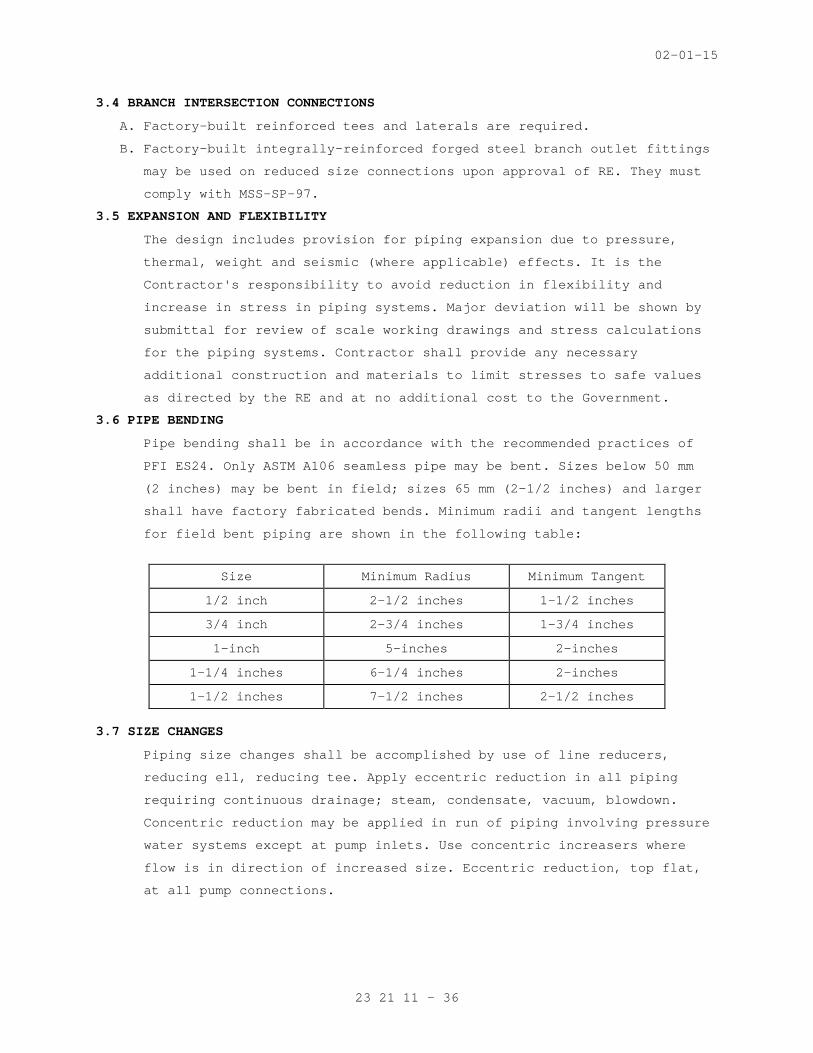
02-01-15
23 21 11 - 36
3.4 BRANCH INTERSECTION CONNECTIONS
A. Factory-built reinforced tees and laterals are required.
B. Factory-built integrally-reinforced forged steel branch outlet fittings
may be used on reduced size connections upon approval of RE. They must
comply with MSS-SP-97.
3.5 EXPANSION AND FLEXIBILITY
The design includes provision for piping expansion due to pressure,
thermal, weight and seismic (where applicable) effects. It is the
Contractor's responsibility to avoid reduction in flexibility and
increase in stress in piping systems. Major deviation will be shown by
submittal for review of scale working drawings and stress calculations
for the piping systems. Contractor shall provide any necessary
additional construction and materials to limit stresses to safe values
as directed by the RE and at no additional cost to the Government.
3.6 PIPE BENDING
Pipe bending shall be in accordance with the recommended practices of
PFI ES24. Only ASTM A106 seamless pipe may be bent. Sizes below 50 mm
(2 inches) may be bent in field; sizes 65 mm (2-1/2 inches) and larger
shall have factory fabricated bends. Minimum radii and tangent lengths
for field bent piping are shown in the following table:
Size Minimum Radius Minimum Tangent
1/2 inch 2-1/2 inches 1-1/2 inches
3/4 inch 2-3/4 inches 1-3/4 inches
1-inch 5-inches 2-inches
1-1/4 inches 6-1/4 inches 2-inches
1-1/2 inches 7-1/2 inches 2-1/2 inches
3.7 SIZE CHANGES
Piping size changes shall be accomplished by use of line reducers,
reducing ell, reducing tee. Apply eccentric reduction in all piping
requiring continuous drainage; steam, condensate, vacuum, blowdown.
Concentric reduction may be applied in run of piping involving pressure
water systems except at pump inlets. Use concentric increasers where
flow is in direction of increased size. Eccentric reduction, top flat,
at all pump connections.
02-01-15
23 21 11 - 37
3.8 ADDITIONAL DRIPS AND TRAPS
Where additional rises or drops in steam or gas lines are provided,
provide additional drip pockets with steam trap assemblies on steam
lines and additional dirt pockets on gas lines. All air drops shall
have dirt legs and no actuator or other air operated equipment may come
off the end of the air line. Airline taps are either from the top of
the supplying line if the supply line is horizontal or from the side if
the supplying line is vertical. All air operated equipment shall have
inline moisture separators or dryers.
3.9 MINOR PIPING
Minor piping associated with instrumentation and control is generally
not shown. Interconnection of sensors, transducers, control devices,
instrumentation panels, combustion control panel, burner control panels
is the responsibility of the contractor. Small piping associated with
water cooling, drips, drains and other minor piping may not be shown to
avoid confusion in the plan presentation but shall be provided as part
of contract work.
3.10 DIELECTRIC CONNECTION
Where copper piping is connected to steel piping provide dielectric
connections.
3.11 INSTALLATION - BOILER EXTERNAL STEAM PIPING FROM BOILER TO MAIN HEADER
A. From Boiler to Second Stop Valve: Fabricate from boiler nozzle through
second stop valve under the rules for boiler external piping of the
ASME Boiler and Pressure Vessel Code, Section I. Full compliance will
be required, including qualification of welders, Code inspection, and
certification with ASME Form P4A. Deliver original of Form P4A properly
executed to RE.
B. Construction shall include: non-return stop and check valve at the
boiler, welding coupling for 20 mm (3/4-inch) vent, second stop valve,
steam flowmeter primary element, welding coupling for IPT calorimeter
connection located to provide clear space and access for temporary test
calorimeter, and header stop valve. Second stop valve may be deleted
if the entire steam line from the non-return valve to the header valve
is constructed in accordance with the rules for boiler external piping,
ASME Section I.
C. Companion flange at 2050 kPa (300 psi) valves shall be 2050 kPa (300
psi) weld neck; at 1025 kPa (150 psi) valves shall be 1025 kPag (150
psi) weld neck.
02-01-15
23 21 11 - 38
D. Equip header stop valve with factory applied warm-up bypass connected
to drilled and tapped bosses in valve body located above and below
valve wedge. Connect valved drain to header valve body boss located
above valve wedge.
E. Equip steam pipe with 20 mm (3/4-inch) vent, 1375 kPa (200 psi) bronze
gate valve, as specified.
F. Support and slope boiler steam line to drain; apply variable spring
hangers (MSS-SP58, Type 51 or 53).
G. Provide screwed fitting for calorimeter (temporary test instrument) on
side of pipe as shown. Allow 600 mm (2 feet) horizontal and vertical
clearance for calorimeter.
H. Handwheel and drain valve on non-return stop-check valve shall be
within easy reach of boiler platform.
I. Disassemble, clean and reassemble entire mechanism of non-return stop
check valve after conclusion of boiler testing.
3.12 INSTALLATION - MAIN STEAM HEADER
A. The header shall be the connection point for steam piping from all
boilers and for steam distribution piping. The boiler plant steam
pressure control transmitter shall be connected to the header.
B. Steam header shall be assembly of tees, pipe sections, and weld neck
flanges.
C. Factory-fabricated forged steel integrally reinforced branch outlet
welding fittings, standard weight, ASTM A105 Grade 2, may be applied in
lieu of tees for all branch outlets less than the full size of the
header. Comply with fitting manufacturer's recommendations and
requirements of ASME B31.1 and MSS-SP-97.
D. Provide header supports and anchor as shown; apply insulation saddles
for insulation thickness as required in Section 23 07 11, HVAC and
BOILER PLANT INSULATION.
E. Weld neck flange bolt position shall conform to required valve, stem,
and bypass orientation as shown.
F. Header construction as specified includes the entire header and
branches to first valve.
G. Anchor and guide header to resist thermal and weight forces and also
seismic forces where required.
H. All valves must be accessible without the use of ladders or chain-
wheels.
02-01-15
23 21 11 - 39
3.13 INSTALLATION - BOILER BOTTOM BLOWOFF PIPING
Fabricate with long swiping radius ells, Y-form laterals. Tees and
crosses are not permitted.
3.14 INSTALLATION - EXHAUST HEAD MOUNTED ABOVE ROOF
Provide drain line from connection on exhaust head to roof drain.
Provide pipe size same as drain connection size.
3.15 INSTALLATION – SIGHT FLOW INDICATORS
Locate to permit view from floor or platform.
3.16 INSTALLATION - PRESSURE AND TEMPERATURE REGULATORS, CONTROL VALVES, SAFETY SHUT-OFF VALVES
Provide sufficient clearance on all sides of valve to permit
replacement of working parts without removing valve from pipeline.
3.17 INSTALLATION - EMERGENCY GAS SAFETY SHUT-OFF VALVES AND EARTHQUAKE VALVES
A. Locate so that valve position indicator is visible from nearest
walkway.
B. Provide control wiring and wiring to annunciator on instrumentation
panel and to computer workstation (if provided).
3.18 INSTALLATION - FLEXIBLE CONNECTORS
Install units for water and compressed air service in a straight run of
pipe. Units for atomizing media service may be installed with bends if
necessary. Designer of atomizing media piping must coordinate hose
connection points with allowable bend radius of hose.
3.19 INSTALLATION - SAFETY VALVES, RELIEF VALVES AND SAFETY-RELIEF VALVES
A. Orient valves so that lifting levers are accessible from nearest
walkway or access platform. Valves must be removable without requiring
disassembling of vents, except where otherwise specifically provided.
B. Provide a drip pan elbow at discharge of each steam or economizer valve
with slip joint in vent discharge line, arranged to prevent vent line
from imposing any force on valve and to prevent any moisture
accumulation in valve. Connected drip pan ell drains to drain piping to
floor drain. Provide flexible connector on drain line, adjacent to drip
pan ell.
C. Support vent line from above. Each steam valve must have separate vent
line to atmosphere unless shown otherwise.
D. Relief valves in steam piping shall have a manual valve downstream of
the relief valve to allow for testing of the valve in place without
risk of over pressurizing downstream equipment.
02-01-15
23 21 11 - 40
3.20 INSTALLATION – Y-TYPE STRAINERS ON STEAM SERVICE
Install with basket level with the steam pipe so that condensate is not
trapped in the strainer.
3.21 INSTALLATION - QUICK COUPLE HOSE CONNECTORS
Install male plugs on each piping drain. Connect socket to one end of
steam hose.
3.22 INSTALLATION - VIBRATION ISOLATORS IN PIPING
A. Install on all air lines and water supply lines to air compressors.
B. Also install on pump connections as shown.
3.23 INSTALLATION - PIPE SLEEVES
A. Accurately locate and securely fasten sleeves to forms before concrete
is poured; install in walls or partitions during the construction of
the walls.
B. Sleeve ends shall be flush with finished faces of walls and partitions.
C. Pipe sleeves passing through floors shall project 25 mm (1 inch)
minimum above the finished floor surface and the bottom of the sleeve
shall be flush with the underside of the floor slab.
3.24 INSTALLATION – PIPE SUPPORT SYSTEMS
A. Coordinate support locations with building structure prior to erection
of piping. Also refer to approved shop drawings of equipment and
approved piping layout and hanger layout drawings when locating
hangers. Arrangement of supports shall facilitate operating, servicing
and removal of valves, strainers, and piping specialties. Hanger parts
must be marked at the factory with a numbering system keyed to hanger
layout drawings. Layout drawings must be available at the site.
B. Upper attachments to Building Structure:
1. New Reinforced Concrete Construction: Concrete inserts.
2. Existing Reinforced Concrete Construction: Upper attachment welded
or clamped to steel clip angles (or other construction shown on the
drawings) which are expansion-bolted to the concrete. Expansion
bolting shall be located so that loads place bolts in shear.
3. Steel Deck and Structural Framing: Upper attachments welded or
clamped to structural steel members.
C. Expansion Fasteners and Power Set Fasteners: In existing concrete
floor, ceiling and wall construction, expansion fasteners may be used
for hanger loads up to one-third the manufacturer's rated strength of
the expansion fastener. Power set fasteners may be used for loads up to
one-fourth of rated load. When greater hanger loads are encountered,
02-01-15
23 21 11 - 41
additional fasteners may be used and interconnected with steel members
combining to support the hanger.
D. Special Supports:
1. Secure horizontal pipes where necessary to prevent vibration or
excess sway.
2. Where hangers cannot be adequately secured as specified, (for
example, support for flow metering sensing lines, pneumatic tubing,
control piping) special provisions shall be made for hanging and
supporting pipe as directed by the RE.
3. Pipe supports, hangers, clamps or anchors shall not be attached to
equipment unless specifically permitted by the specifications for
that equipment or unless RE gives written permission. No attachments
to boiler casings permitted.
E. Spring Hangers: Locate spring units within one foot of the pipe,
breeching or stack attachment except in locations where spring
assemblies interfere with pipe insulation. Adjust springs to loads
calculated by hanger manufacturer.
F. Seismic Braces and Restraints: Do not insulate piping within one foot
of device until device has been inspected by RE.
3.25 CLEANING OF PIPING AFTER INSTALLATION
Flush all piping sufficiently to remove all dirt and debris. Fill
piping completely. Velocity shall be equivalent to that experienced
during normal plant operation at maximum loads. During flushing, all
control valves, steam traps and pumps must be disconnected from the
system. After cleaning is complete, remove, clean and replace all
strainer baskets and elements. Reconnect all equipment. Provide safe
points of discharge for debris blown from pipes.
3.26 TESTING
A. Testing of piping components is not required prior to installation.
Valves and fittings shall be capable of withstanding hydrostatic shell
test equal to twice the primary design service pressure except as
modified by specifications on fittings, ASME B16.5. This test
capability is a statement of quality of material. Tests of individual
items of pipe, fittings or equipment will be required only on
instruction of RE and at Government cost.
B. After erection, all piping systems shall be capable of withstanding a
hydrostatic test pressure of 1.5 times design pressure, as stipulated
in ASME B31.1. Hydrostatic tests will be required only on boiler
02-01-15
23 21 11 - 42
external steam piping, utilizing water as the test medium. Hydrostatic
tests will be required on other piping when operating tests described
are unsatisfactory, or when inspection of welds shows poor workmanship
and is subject to question by the RE. When hydrostatic tests show
leaks, the RE will require necessary welding repairs, in accordance
with ASME B31.1, at the Contractor's cost.
C. Perform operating test as follows:
1. All steam piping prior to insulation shall be subjected to steam at
final operating pressure. Inspect all joints for leaks and
workmanship. Corrections shall be made as specified.
2. Test main gas piping with compressed air at twice the service
pressure entering VA property from utility service. Test LP gas
piping at the maximum tank pressure, 1725 kPa (250 psig), with
compressed air. Test joints with soap solution, check thoroughly for
leaks.
3. Test boiler feedwater, condensate, vacuum and service water systems
under service conditions and prove tight.
4. Test oil and compressed air systems under service conditions at
pressure equal to highest setting of safety and relief valves in the
individual systems.
5. Make corrections and retests to establish systems that have no
leaks. Replace or recut any defective fittings or defective threads.
Soldered material shall be thoroughly cleaned prior to resoldering.
Back welding of threads will not be permitted.
D. Hydrostatically test boiler external steam piping from boiler to header
in approved manner with water of same time boiler is hydrostatically
tested under the supervision of RE. Prior to hydrostatic test, remove
all valves not rated for hydrostatic test pressure. Replace valves
after tests are satisfactorily completed. Hydrostatic test pressure
shall be 1.5 times design pressure and performed in accordance with
ASME Boiler and Pressure Vessel Code, Section I.
02-01-15
23 21 11 - 43
E. Generally, insulation work should not be performed prior to testing of
piping. Contractor may, at own option and hazard, insulate piping prior
to test, but any damaged insulation shall be replaced with new quality
as specified for original installation at Contractor's cost and time.
F. Safety, Safety-Relief, Relief Valves: After installation, test under
pressure in presence of RE. Test operation, including set pressure,
flow, and blowdown in accordance with ASME Boiler and Pressure Vessel
Code. Any deficiencies must be corrected and retest performed. Refer to
Section 23 52 39, FIRE-TUBE BOILERS, Section 23 52 33, WATER-TUBE
BOILERS for boiler safety valve test requirements.
3.27 COMMISSIONING
A. Provide commissioning documentation in accordance with the requirements
of section 23 08 00 – COMMISSIONING OF HVAC SYSTEMS for all inspection,
start up, and contractor testing required above and required by the
System Readiness Checklist provided by the Commissioning Agent.
B. Components provided under this section of the specification will be
tested as part of a larger system. Refer to section 23 08 00 –
COMMISSIONING OF HVAC SYSTEMS and related sections for contractor
responsibilities for system commissioning.
- - - E N D - - -