Embed Size (px)
Citation preview

VA-LCP® Clavicle Hook Plate 2.7 SystemSurgical Technique

Image intensifier control
This description alone does not provide sufficient background for direct use of DePuy Synthes products. Instruction by a surgeon experienced in handling these products is highly recommended.
Processing, Reprocessing, Care and MaintenanceFor general guidelines, function control and dismantling of multi-part instruments, as well as processing guidelines for implants, please contact your local sales representative or refer to:http://emea.depuysynthes.com/hcp/reprocessing-care-maintenanceFor general information about reprocessing, care and maintenance of Synthes reusable devices, instrument trays and cases, as well as processing of Synthes non-sterile implants, please consult the Important Information leaflet (SE_023827) or refer to: http://emea.depuysynthes.com/hcp/reprocessing-care-maintenance
Introduction
Surgical Technique
Product Information
Table of Contents
VA-LCP® Clavicle Hook Plate 2.7 System Surgical Technique DePuy Synthes 1
VA-LCP Clavicle Hook Plate 2.7 System 2
DePuy Synthes Clavicle Portfolio 4
The AO Principles of Fracture Management 6
Indications/Contraindications 7
Preparation 8
Approach 9
Preparation of Hook Tunnel and Preliminary 10 Reduction of the AC Joint and/or Lateral Clavicle
Determine Hook Depth and Plate Shape 11
Select Hook Depth and Plate Shape 15
Adapt Plate to Bone (Optional) 16
Plate Insertion 18
Screw Configuration 19
Screw Insertion – 2.7 mm Cortex Screws 23
Screw Insertion – 2.7 mm VA Locking Screws and 26Metaphyseal Screws
Soft Tissue Attachment (Optional) 32
Reduction and Fixation Confirmation 33
Surgical Closure 33
Implant Removal 34
Implants 35
Templates 37
Instruments 38
MRI Safety Information 42
Sets 43
2 DePuy Synthes VA-LCP® Clavicle Hook Plate 2.7 System Surgical Technique
The VA-LCP® Clavicle Hook Plate 2.7 System provides solutions for lateral clavicle fractures with associated acromioclavicular (AC) ligament and coracoclavicular (CC) ligaments injuries. Literature shows that several factors including severity of displacement, instability, and injury to the surrounding ligaments contribute to the need for operative treatment due to high rates of nonunion and delayed union when treated conservatively.1
The DePuy Synthes VA-LCP Hook Plate 2.7 System also provides a solution for ligamentous injuries without a clavicle fracture. Literature shows that higher grade ligamentous injuries of the AC joint should be treated operatively to prevent persistent instability causing pain.2
In operatively treated lateral clavicle fractures and isolated ligamentous injuries, a mismatch between the hook plate and the diverse anatomy of the acromion and the lateral clavicle can lead to short-term complaints including
System Overview
VA-LCP® Clavicle Hook Plate 2.7 System
1. Tiren D, van Bemmel A, Swank D, et al. Hook plate fi xation of acute displaced lateral clavicle fractures: mid-term results and a brief literature overview. J Orthop Surg Res. 2012;7:2.
2. Tauber, M. Management of acute acromioclavicular joint dislocations: current concepts. Arch Orthop Trauma Surg. 2013;133(7):985-95.
3. Compared to Stryker VariAx 2 Clavicle System and DePuy Synthes 3.5 LCP® Clavicle System. DePuy Synthes. Hook Shape Verifi cation, Windchill #0000290741, 2020.
4. Engineering Memo Optimization of Subacromial Hook Parameters, Windchill #0000277700, 2020.
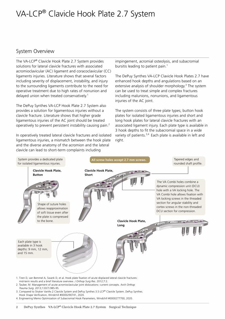
Each plate type is available in 3 hook depths: 9 mm, 12 mm, and 15 mm.
System provides a dedicated plate for isolated ligamentous injuries.
All screw holes accept 2.7 mm screws.
The VA Combi holes combine a dynamic compression unit (DCU) hole with a VA locking hole. The VA Combi hole allows fi xation with VA locking screws in the threaded section for angular stability and cortex screws in the non-threaded DCU section for compression.
Shape of suture holes allows reapproximation of soft tissue even after the plate is compressed to the bone.
Tapered edges and rounded shaft profi le.
impingement, acromial osteolysis, and subacromial bursitis leading to patient pain.1
The DePuy Synthes VA-LCP Clavicle Hook Plates 2.7 have enhanced hook depths and angulations based on an extensive analysis of shoulder morphology.3 The system can be used to treat simple and complex fractures including malunions, nonunions, and ligamentous injuries of the AC joint.
The system consists of three plate types; button hook plates for isolated ligamentous injuries and short and long hook plates for lateral clavicle fractures with an associated ligament injury. Each plate type is available in 3 hook depths to fi t the subacromial space in a wide variety of patients.3,4 Each plate is available in left and right.
Clavicle Hook Plate, Button
Clavicle Hook Plate, Short
Clavicle Hook Plate, Long
VA-LCP® Clavicle Hook Plate 2.7 System Surgical Technique DePuy Synthes 3
5. Compared to Stryker Variax 2 Clavicle System and DePuy Synthes 3.5 LCP®
Clavicle System. DePuy Synthes. Hook Shape Verifi cation, Windchill #0000290741, 2020.
6. DePuy Synthes. Competitive Analysis, Windchill #0000294554, 2020.
VA-LCP® Clavicle Hook Plate 2.7 System
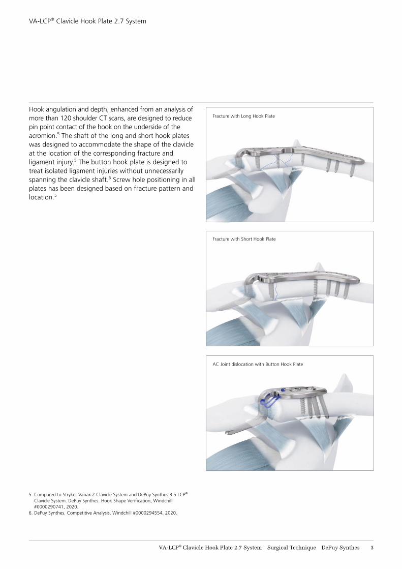
Hook angulation and depth, enhanced from an analysis of more than 120 shoulder CT scans, are designed to reduce pin point contact of the hook on the underside of the acromion.5 The shaft of the long and short hook plates was designed to accommodate the shape of the clavicle at the location of the corresponding fracture and ligament injury.5 The button hook plate is designed to treat isolated ligament injuries without unnecessarily spanning the clavicle shaft.6 Screw hole positioning in all plates has been designed based on fracture pattern and location.5
Fracture with Long Hook Plate
Fracture with Short Hook Plate
AC Joint dislocation with Button Hook Plate

4 DePuy Synthes VA-LCP® Clavicle Hook Plate 2.7 System Surgical Technique
DePuy Synthes offers a full portfolio of complementary plating systems for clavicle fractures and AC joint injuries. In addition to the VA-LCP® Clavicle Hook Plate 2.7 system described in this surgical technique guide, DePuy Synthes offers the VA-LCP® Clavicle Plate 2.7 system and the VA-LCP® Anterior Clavicle Plates 2.7/3.5.
VA-LCP Clavicle Plate System• Plate shapes match the bow and contour of the
clavicle for low construct prominence and enhanced plate-to-bone fit7
• Plate selection based on correlation between patient height and clavicle size
• System includes a dedicated plate designed to treat medial clavicle fractures
DePuy Synthes Clavicle Portfolio
Lateral Plate, right
Shaft Plate, right
Medial Plate, right
7. Compared to Stryker VariAx 2 Clavicle System and Acumed Clavicle System. DePuy Synthes. Shape Verification Analyses. Windchill #0000290902, 0000295170, 0000290186, 2020.
VA-LCP® Clavicle Hook Plate 2.7 System Surgical Technique DePuy Synthes 5
DePuy Synthes Clavicle Portfolio
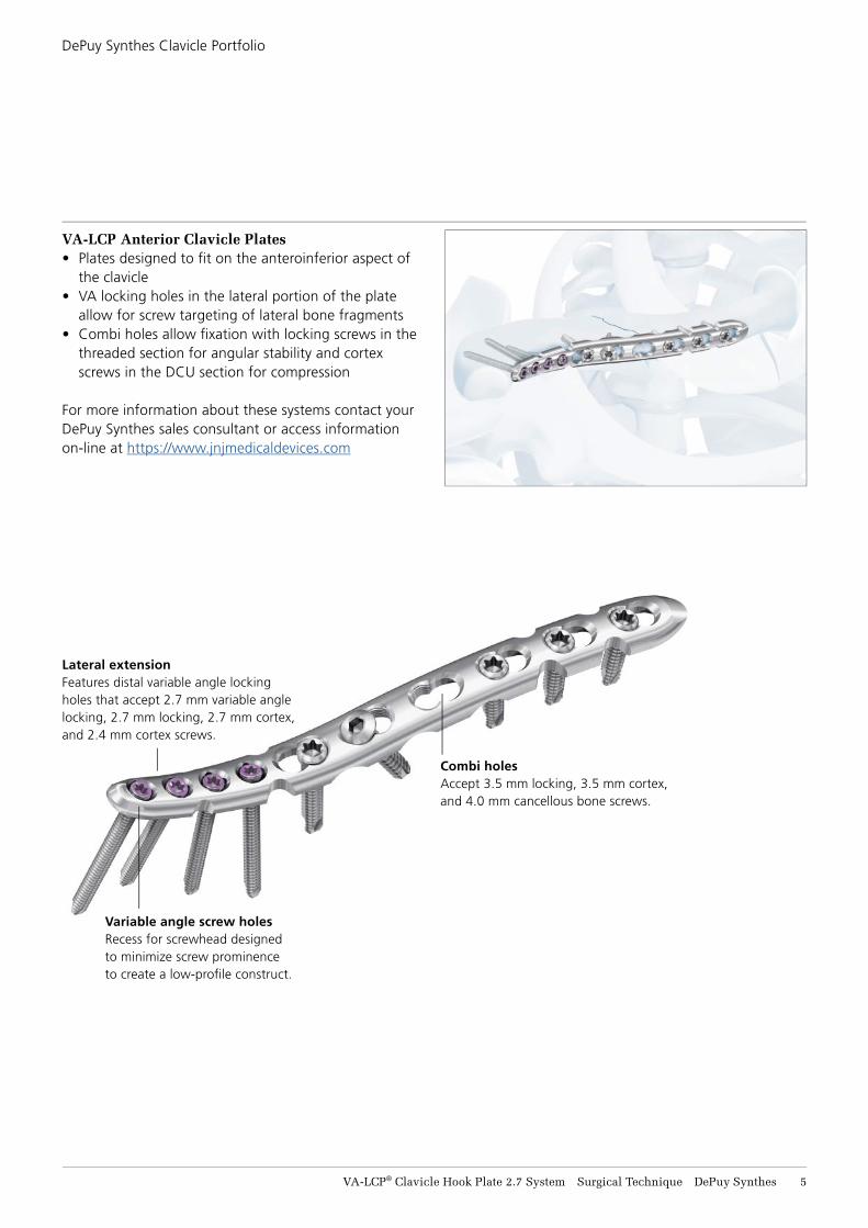
Lateral extensionFeatures distal variable angle locking holes that accept 2.7 mm variable angle locking, 2.7 mm locking, 2.7 mm cortex, and 2.4 mm cortex screws.
Combi holesAccept 3.5 mm locking, 3.5 mm cortex, and 4.0 mm cancellous bone screws.
Variable angle screw holesRecess for screwhead designed to minimize screw prominence to create a low-profi le construct.
VA-LCP Anterior Clavicle Plates• Plates designed to fi t on the anteroinferior aspect of
the clavicle • VA locking holes in the lateral portion of the plate
allow for screw targeting of lateral bone fragments• Combi holes allow fi xation with locking screws in the
threaded section for angular stability and cortex screws in the DCU section for compression
For more information about these systems contact your DePuy Synthes sales consultant or access information on-line at https://www.jnjmedicaldevices.com
6 DePuy Synthes VA-LCP® Clavicle Hook Plate 2.7 System Surgical Technique
The AO Principles of Fracture Management
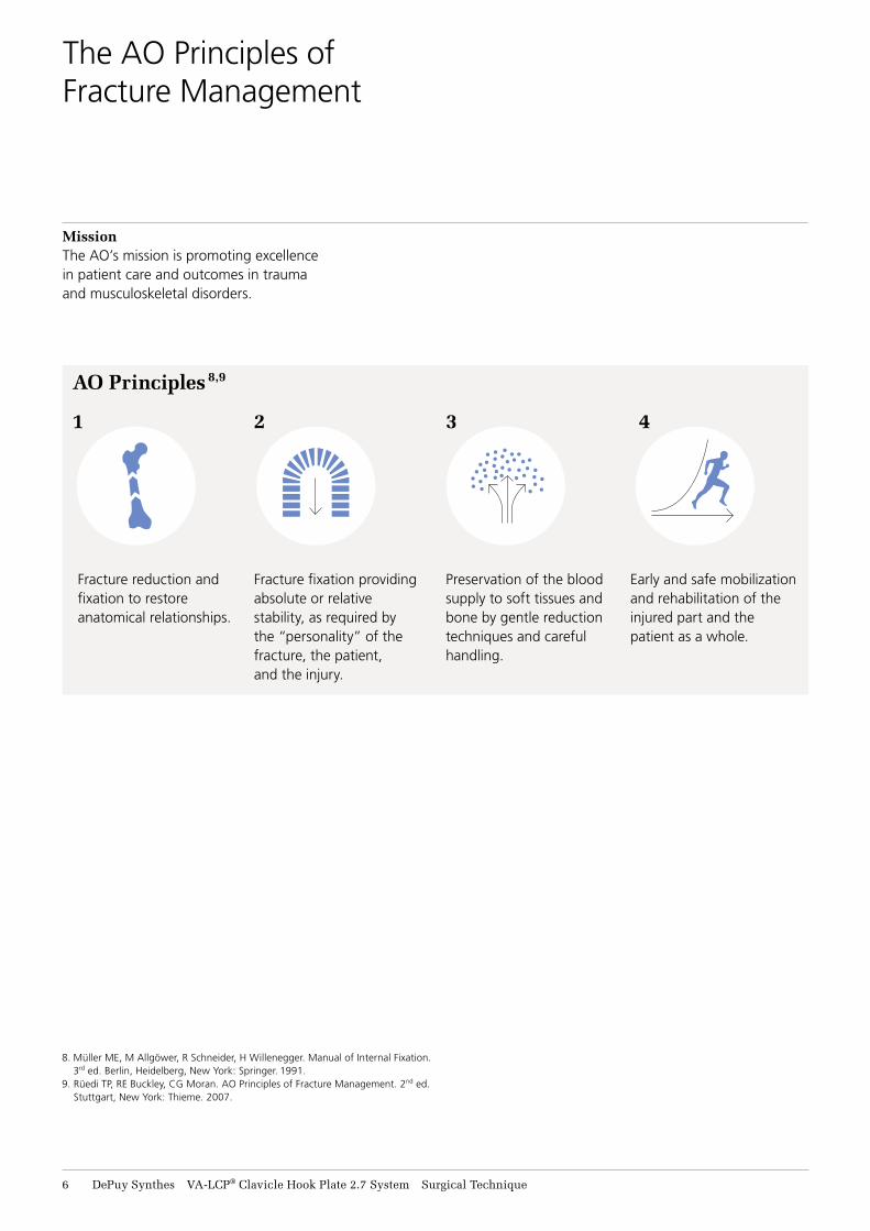
Fracture reduction andfixation to restoreanatomical relationships.
MissionThe AO’s mission is promoting excellencein patient care and outcomes in traumaand musculoskeletal disorders.
Fracture fixation providing absolute or relative stability, as required by the “personality” of the fracture, the patient, and the injury.
Preservation of the blood supply to soft tissues and bone by gentle reduction techniques and careful handling.
Early and safe mobilization and rehabilitation of the injured part and the patient as a whole.
3 4
AO Principles 8,9
1 2
8. Müller ME, M Allgöwer, R Schneider, H Willenegger. Manual of Internal Fixation. 3rd ed. Berlin, Heidelberg, New York: Springer. 1991.
9. Rüedi TP, RE Buckley, CG Moran. AO Principles of Fracture Management. 2nd ed. Stuttgart, New York: Thieme. 2007.

VA-LCP® Clavicle Hook Plate 2.7 System Surgical Technique DePuy Synthes 7
Indications
VA-LCP Clavicle Hook Plates 2.7 long and short• Fixation of lateral clavicle fractures and dislocations of
the acromioclavicular joint
VA-LCP Clavicle Button Hook Plates 2.7 • Fixation of acromioclavicular joint dislocations
Contraindications
VA-LCP Clavicle Hook Plates 2.7 long and short • Stable lateral clavicle fractures • Fixation of sternoclavicular joint • Systemic infection or infection localized to the site of
the proposed implantation
VA-LCP Clavicle Button Hook Plates 2.7 • Fixation of sternoclavicular joint • Systemic infection or infection localized to the site of
the proposed implantation
Indications/Contraindications
8 DePuy Synthes VA-LCP® Clavicle Hook Plate 2.7 System Surgical Technique
1. Preparation
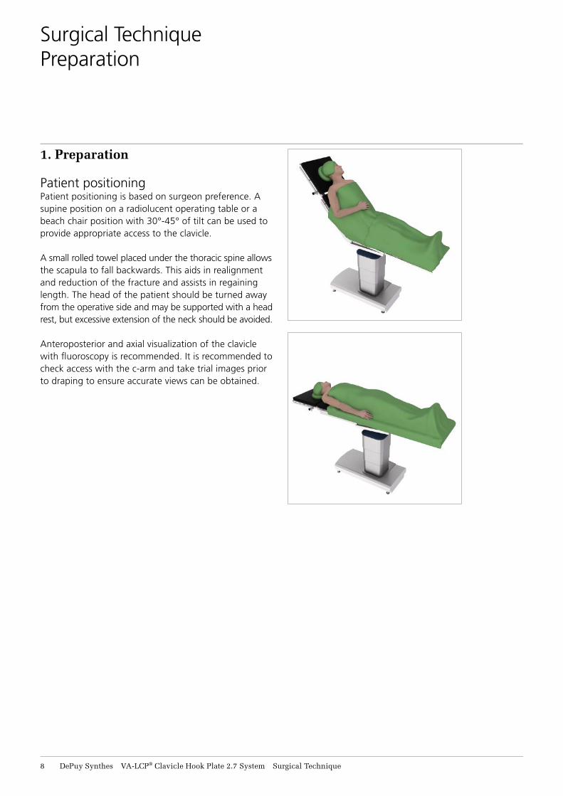
Patient positioningPatient positioning is based on surgeon preference. A supine position on a radiolucent operating table or a beach chair position with 30°-45° of tilt can be used to provide appropriate access to the clavicle.
A small rolled towel placed under the thoracic spine allows the scapula to fall backwards. This aids in realignment and reduction of the fracture and assists in regaining length. The head of the patient should be turned away from the operative side and may be supported with a head rest, but excessive extension of the neck should be avoided.
Anteroposterior and axial visualization of the clavicle with fl uoroscopy is recommended. It is recommended to check access with the c-arm and take trial images prior to draping to ensure accurate views can be obtained.
Surgical TechniquePreparation
VA-LCP® Clavicle Hook Plate 2.7 System Surgical Technique DePuy Synthes 9
Surgical Technique
Approach
2. Approach
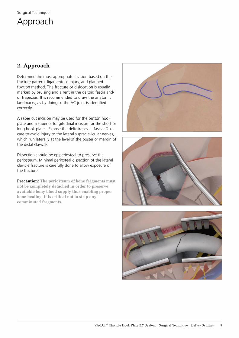
Determine the most appropriate incision based on the fracture pattern, ligamentous injury, and planned fi xation method. The fracture or dislocation is usually marked by bruising and a rent in the deltoid fascia and/or trapezius. It is recommended to draw the anatomic landmarks; as by doing so the AC joint is identifi ed correctly.
A saber cut incision may be used for the button hook plate and a superior longitudinal incision for the short or long hook plates. Expose the deltotrapezial fascia. Take care to avoid injury to the lateral supraclavicular nerves, which run laterally at the level of the posterior margin of the distal clavicle.
Dissection should be epiperiosteal to preserve the periosteum. Minimal periosteal dissection of the lateral clavicle fracture is carefully done to allow exposure of the fracture.
Precaution: The periosteum of bone fragments must not be completely detached in order to preserve available bony blood supply thus enabling proper bone healing. It is critical not to strip any comminuted fragments.
10 DePuy Synthes VA-LCP® Clavicle Hook Plate 2.7 System Surgical Technique
3. Preparation of the Hook Tunnel and Preliminary Reduction of the AC Joint and/or Lateral Clavicle
Instruments
292.200.01 Kirschner Wire Ø 2.0 mm, w/trocar tip, L 150 mm
292.160.01 Kirschner Wire Ø 1.6 mm, w/trocar tip, L 150 mm
03.112.810– Templates for VA-LCP Clavicle Hook 03.112.815 Plate 2.7, Long
03.112.820– Templates for VA-LCP Clavicle Hook 03.112.825 Plate 2.7, Short
03.112.910– Templates for VA-LCP Clavicle Hook 03.112.915 Plate 2.7, Button
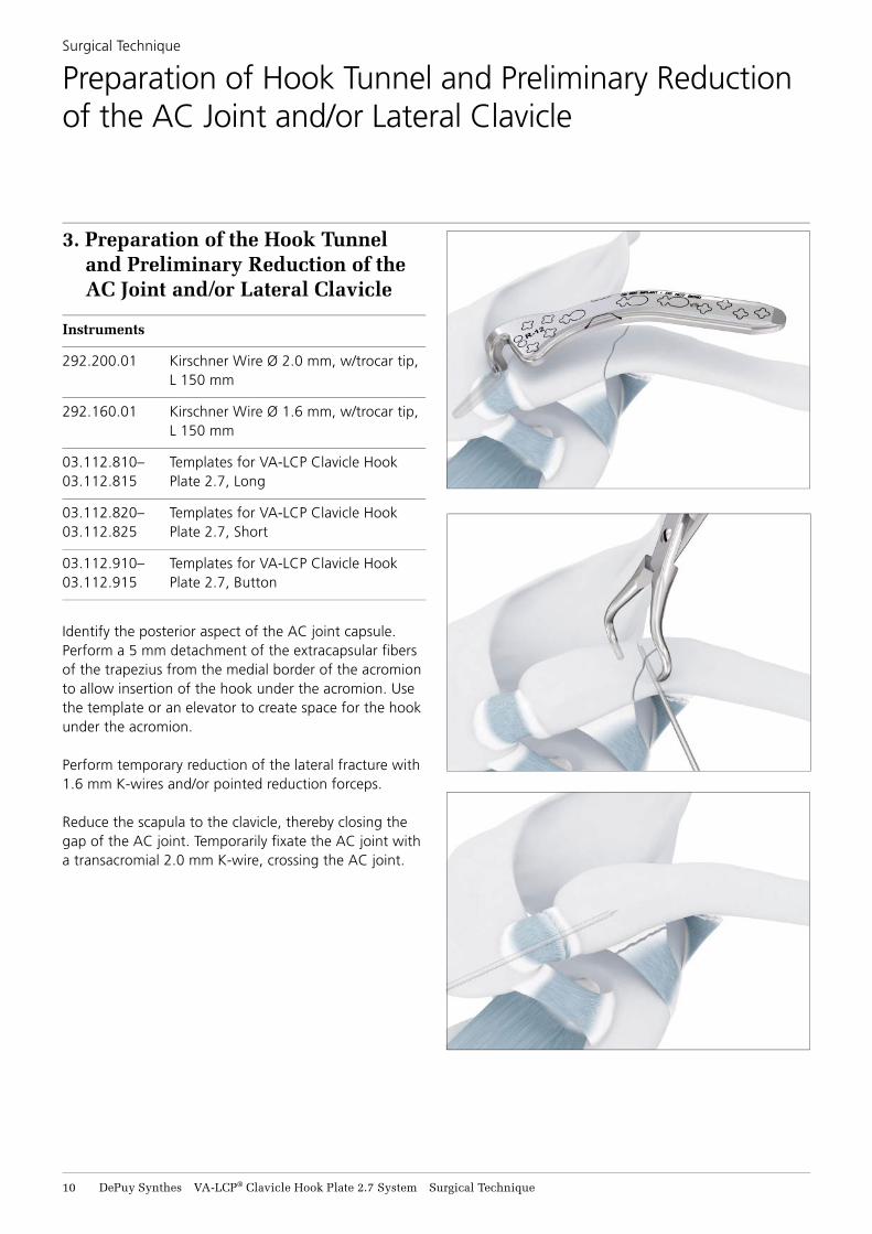
Identify the posterior aspect of the AC joint capsule. Perform a 5 mm detachment of the extracapsular fi bers of the trapezius from the medial border of the acromion to allow insertion of the hook under the acromion. Use the template or an elevator to create space for the hook under the acromion.
Perform temporary reduction of the lateral fracture with 1.6 mm K-wires and/or pointed reduction forceps.
Reduce the scapula to the clavicle, thereby closing the gap of the AC joint. Temporarily fi xate the AC joint with a transacromial 2.0 mm K-wire, crossing the AC joint.
Surgical Technique
Preparation of Hook Tunnel and Preliminary Reduction of the AC Joint and/or Lateral Clavicle

VA-LCP® Clavicle Hook Plate 2.7 System Surgical Technique DePuy Synthes 11
4. Determine Hook Depth and Plate Shape
Instruments
03.112.810– Templates for VA-LCP Clavicle Hook 03.112.815 Plate 2.7, Long
03.112.820– Templates for VA-LCP Clavicle Hook 03.112.825 Plate 2.7, Short
03.112.910– Templates for VA-LCP Clavicle Hook 03.112.915 Plate 2.7, Button
Use templates to determine the appropriate plate shape and hook depth.
Each template and corresponding plate are available in 3 shapes and each shape is offered with 3 hook depths.
Surgical Technique
Determine Hook Depth and Plate Shape
Hook Depths
Plate Shapes
9 mm Hook Depth 12 mm Hook Depth 15 mm Hook Depth
Button
Short
Long
Hook depth9, 12, or 15 mm
D
Long Template
Short Template
Button Template
12 DePuy Synthes VA-LCP® Clavicle Hook Plate 2.7 System Surgical Technique
4. Determine Hook Depth and Plate Shape continued
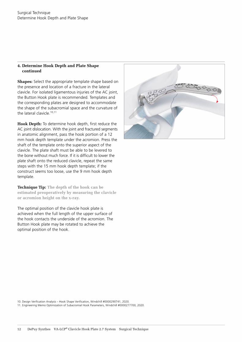
Shapes: Select the appropriate template shape based on the presence and location of a fracture in the lateralclavicle. For isolated ligamentous injuries of the AC joint, the Button Hook plate is recommended. Templates and the corresponding plates are designed to accommodate the shape of the subacromial space and the curvature of the lateral clavicle.10,11
Hook Depth: To determine hook depth, fi rst reduce the AC joint dislocation. With the joint and fractured segments in anatomic alignment, pass the hook portion of a 12 mm hook depth template under the acromion. Press the shaft of the template onto the superior aspect of the clavicle. The plate shaft must be able to be levered to the bone without much force. If it is diffi cult to lower the plate shaft onto the reduced clavicle, repeat the same steps with the 15 mm hook depth template; if the construct seems too loose, use the 9 mm hook depth template.
Technique Tip: The depth of the hook can be estimated preoperatively by measuring the clavicle or acromion height on the x-ray.
The optimal position of the clavicle hook plate is achieved when the full length of the upper surface of the hook contacts the underside of the acromion. The Button Hook plate may be rotated to achieve the optimal position of the hook.
Surgical TechniqueDetermine Hook Depth and Plate Shape
10. Design Verifi cation Analysis – Hook Shape Verifi cation, Windchill #0000290741, 2020.11. Engineering Memo Optimization of Subacromial Hook Parameters, Windchill #0000277700, 2020.
VA-LCP® Clavicle Hook Plate 2.7 System Surgical Technique DePuy Synthes 13
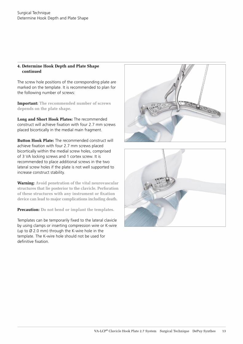
4. Determine Hook Depth and Plate Shape continued
The screw hole positions of the corresponding plate are marked on the template. It is recommended to plan for the following number of screws:
Important: The recommended number of screws depends on the plate shape.
Long and Short Hook Plates: The recommended construct will achieve fi xation with four 2.7 mm screws placed bicortically in the medial main fragment.
Button Hook Plate: The recommended construct will achieve fi xation with four 2.7 mm screws placed bicortically within the medial screw holes, comprised of 3 VA locking screws and 1 cortex screw. It is recommended to place additional screws in the two lateral screw holes if the plate is not well supported to increase construct stability.
Warning: Avoid penetration of the vital neurovascular structures that lie posterior to the clavicle. Perforation of these structures with any instrument or fi xation device can lead to major complications including death.
Precaution: Do not bend or implant the templates.
Templates can be temporarily fi xed to the lateral clavicle by using clamps or inserting compression wire or K-wire (up to Ø 2.0 mm) through the K-wire hole in the template. The K-wire hole should not be used for defi nitive fi xation.
Surgical TechniqueDetermine Hook Depth and Plate Shape
14 DePuy Synthes VA-LCP® Clavicle Hook Plate 2.7 System Surgical Technique
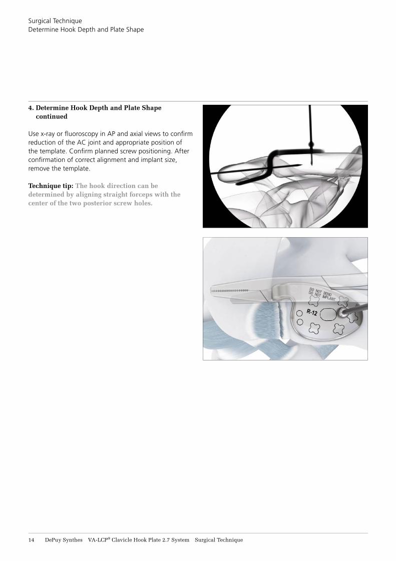
4. Determine Hook Depth and Plate Shape continued
Use x-ray or fl uoroscopy in AP and axial views to confi rm reduction of the AC joint and appropriate position of the template. Confi rm planned screw positioning. After confi rmation of correct alignment and implant size, remove the template.
Technique tip: The hook direction can be determined by aligning straight forceps with the center of the two posterior screw holes.
Surgical TechniqueDetermine Hook Depth and Plate Shape
VA-LCP® Clavicle Hook Plate 2.7 System Surgical Technique DePuy Synthes 15
5. Select Hook Depth and Plate Shape
Instruments
03.211.001* Holding Pin for VA Locking Plates 2.4/2.7 mm
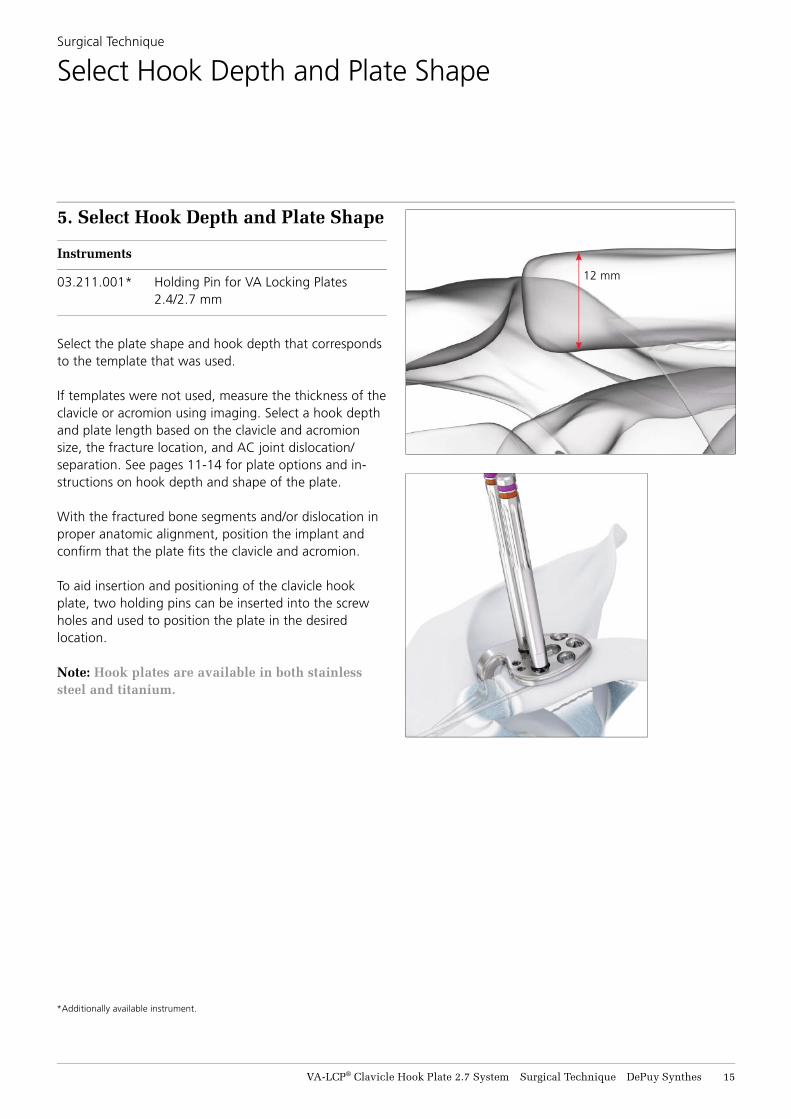
Select the plate shape and hook depth that corresponds to the template that was used.
If templates were not used, measure the thickness of the clavicle or acromion using imaging. Select a hook depth and plate length based on the clavicle and acromion size, the fracture location, and AC joint dislocation/separation. See pages 11-14 for plate options and in-structions on hook depth and shape of the plate.
With the fractured bone segments and/or dislocation in proper anatomic alignment, position the implant and confi rm that the plate fi ts the clavicle and acromion.
To aid insertion and positioning of the clavicle hook plate, two holding pins can be inserted into the screw holes and used to position the plate in the desired location.
Note: Hook plates are available in both stainless steel and titanium.
Surgical Technique
Select Hook Depth and Plate Shape
*Additionally available instrument.
12 mm

16 DePuy Synthes VA-LCP® Clavicle Hook Plate 2.7 System Surgical Technique
6. Adapt Plate to Bone (optional)
Instruments
03.133.200 Bending Iron f/Plates, closed, f/Plates 2.7/3.5 mm
03.133.201 Bending Iron f/Plates, open, f/Plates 2.7/3.5 mm
329.291 Bending Pliers f/Clavicular Plates, L 227 mm
Precautions: • Do not bend more than 10° as it may impact the
mechanical performance of the plate. Excessive bending may weaken the plate and lead to prema-ture plate failure.
• Avoid reverse bending (i.e., bending and then straightening the plate) as it may compromise the strength of the plate or cause it to break.
• Do not make an acute bend directly over a screw hole as it may damage the thread. Check the VA portion of the VA Combi holes adjacent to the bending site with a variable angle drill guide after bending to ensure holes have not been deformed.
• Nominal screw angle is determined by plate design and screw length. If the plate is contoured and/or a screw longer than 40 mm is selected, take care to ensure that screws do not collide with one another. The use of image intensifi cation is recommended.
Check if the plate shape and hook depth are satisfac-tory. Due to the high degree of variability of the acromiocla-vicular anatomy, plate bending may be necessary. Use bending pliers or bending irons for out-of-plane bending and bending irons for torsional bending.
Plates may be contoured up to 10°.
Surgical Technique
Adapt Plate to Bone (Optional)
Plate bending
VA-LCP® Clavicle Hook Plate 2.7 System Surgical Technique DePuy Synthes 17
Surgical TechniqueAdapt Plate to Bone (Optional)
6. Adapt Plate to Bone continued
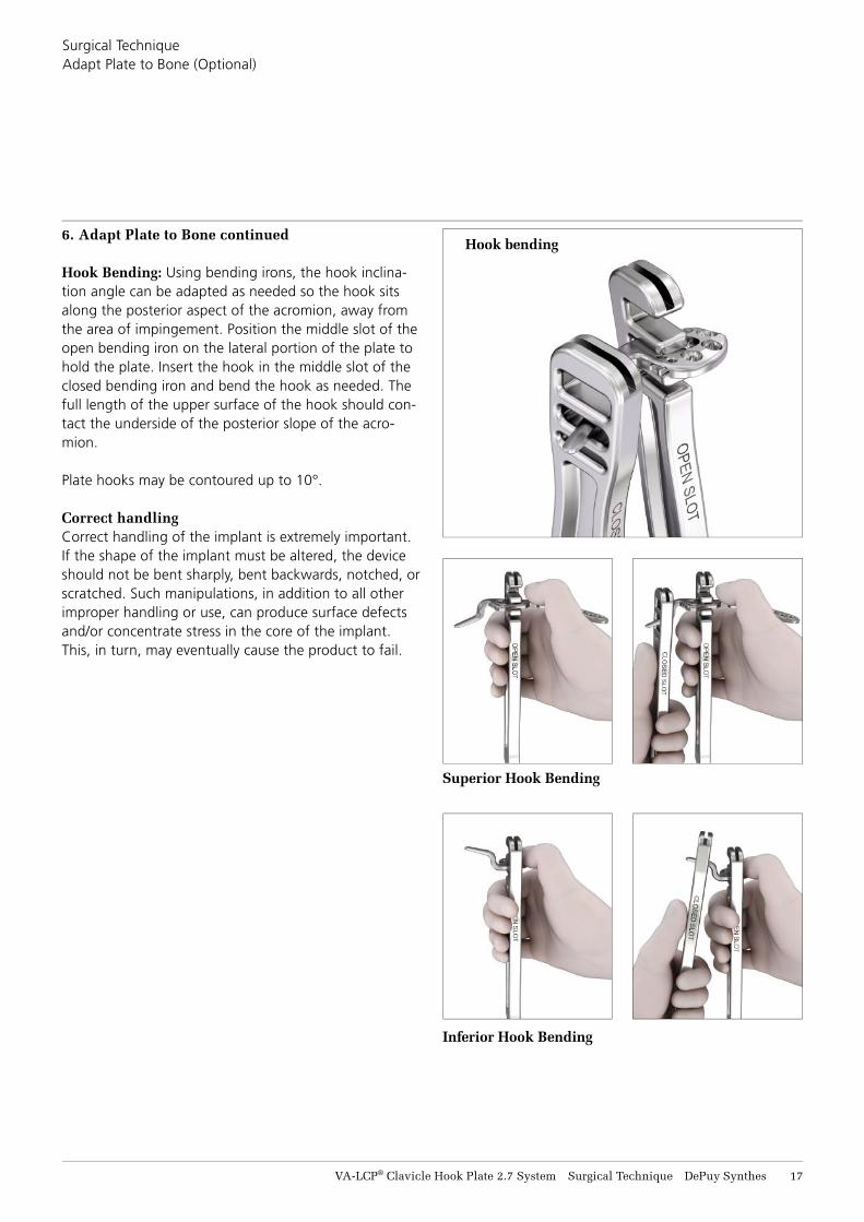
Hook Bending: Using bending irons, the hook inclina-tion angle can be adapted as needed so the hook sits along the posterior aspect of the acromion, away from the area of impingement. Position the middle slot of the open bending iron on the lateral portion of the plate to hold the plate. Insert the hook in the middle slot of the closed bending iron and bend the hook as needed. The full length of the upper surface of the hook should con-tact the underside of the posterior slope of the acro-mion.
Plate hooks may be contoured up to 10°.
Correct handling Correct handling of the implant is extremely important. If the shape of the implant must be altered, the device should not be bent sharply, bent backwards, notched, or scratched. Such manipulations, in addition to all other improper handling or use, can produce surface defects and/or concentrate stress in the core of the implant. This, in turn, may eventually cause the product to fail.
Superior Hook Bending
Inferior Hook Bending
Hook bending

B
18 DePuy Synthes VA-LCP® Clavicle Hook Plate 2.7 System Surgical Technique
7. Plate Insertion
Instruments
292.160.01 Kirschner Wire Ø 1.6 mm, w/trocar tip, L 150 mm
03.211.410.01 Compression Wire Ø 1.6 mm, L 150 mm, thread length 10 mm
03.211.415.01 Compression Wire Ø 1.6 mm, L 150 mm, thread length 15 mm
Insert the hook under the acromion and position the plate on the superior aspect of the lateral clavicle. Attach it temporarily using any of the following techniques.
A. Cortex screw or metaphyseal screwB. Reduction forceps/serrated clamps C. Compression wire D. K-wire in suture hole
It is important to center the compression wire within the plate holes to minimize shifting of the plate position as the wire pulls the plate to the bone.
A K-wire up to Ø 2.0 mm can be inserted in the lateral suture hole or K-wire hole as a reference to visualize the lateral aspect of the clavicle and aid in proper plate placement.
Warning: Avoid penetration of the vital neurovascular structures that lie posterior to the clavicle. Perforation of these structures with any instrument or fi xation device can lead to major complications including death.
After plate insertion, confi rm fi t and alignment of the bone using fl uoroscopy.
Technique tip: The suture holes are designed with an undercut to allow for suture needle passage (see page 32). However, depending on the individual patient’s anatomy, the undercut may be blocked and no needle passage possible. In this case, insert the suture through the suture holes before starting with fi nal plate fi xation.
Surgical Technique
Plate Insertion
A
B
C
D
VA-LCP® Clavicle Hook Plate 2.7 System Surgical Technique DePuy Synthes 19
8. Screw Confi guration
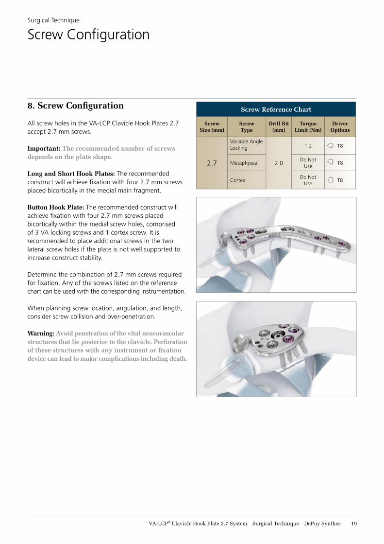
All screw holes in the VA-LCP Clavicle Hook Plates 2.7 accept 2.7 mm screws.
Important: The recommended number of screws depends on the plate shape.
Long and Short Hook Plates: The recommended construct will achieve fi xation with four 2.7 mm screws placed bicortically in the medial main fragment.
Button Hook Plate: The recommended construct will achieve fi xation with four 2.7 mm screws placed bicortically within the medial screw holes, comprised of 3 VA locking screws and 1 cortex screw. It is recommended to place additional screws in the two lateral screw holes if the plate is not well supported to increase construct stability.
Determine the combination of 2.7 mm screws required for fi xation. Any of the screws listed on the reference chart can be used with the corresponding instrumentation.
When planning screw location, angulation, and length, consider screw collision and over-penetration.
Warning: Avoid penetration of the vital neurovascular structures that lie posterior to the clavicle. Perforation of these structures with any instrument or fi xation device can lead to major complications including death.
Surgical Technique
Screw Confi guration
Screw Reference Chart
Screw Size (mm)
Screw Type
Drill Bit (mm)
Torque Limit (Nm)
Driver Options
2.7
Variable Angle Locking
2.0
1.2 T8
MetaphysealDo Not
UseT8
CortexDo Not
UseT8
20 DePuy Synthes VA-LCP® Clavicle Hook Plate 2.7 System Surgical Technique
Surgical TechniqueScrew Confi guration
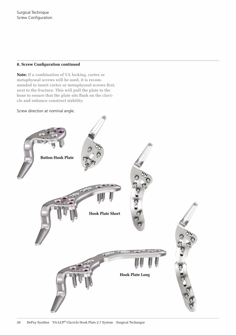
Hook Plate Long
Hook Plate Short
Button Hook Plate
8. Screw Confi guration continued
Note: If a combination of VA locking, cortex or metaphyseal screws will be used, it is recom-mended to insert cortex or metaphyseal screws fi rst, next to the fracture. This will pull the plate to the bone to ensure that the plate sits fl ush on the clavi-cle and enhance construct stability.
Screw direction at nominal angle.
1
3
2
2
2
VA-LCP® Clavicle Hook Plate 2.7 System Surgical Technique DePuy Synthes 21
8. Screw Confi guration continued
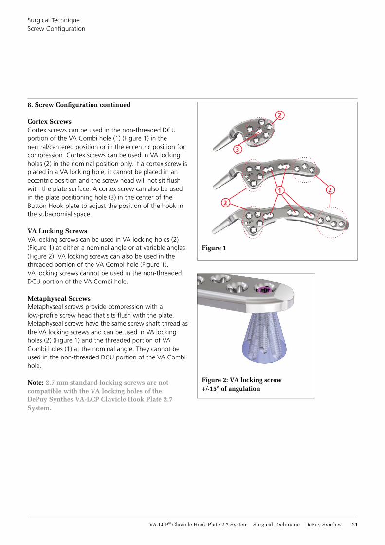
Cortex ScrewsCortex screws can be used in the non-threaded DCU portion of the VA Combi hole (1) (Figure 1) in the neutral/centered position or in the eccentric position for compression. Cortex screws can be used in VA locking holes (2) in the nominal position only. If a cortex screw is placed in a VA locking hole, it cannot be placed in an eccentric position and the screw head will not sit fl ush with the plate surface. A cortex screw can also be used in the plate positioning hole (3) in the center of the Button Hook plate to adjust the position of the hook in the subacromial space.
VA Locking Screws VA locking screws can be used in VA locking holes (2) (Figure 1) at either a nominal angle or at variable angles (Figure 2). VA locking screws can also be used in the threaded portion of the VA Combi hole (Figure 1). VA locking screws cannot be used in the non-threaded DCU portion of the VA Combi hole.
Metaphyseal ScrewsMetaphyseal screws provide compression with a low-profi le screw head that sits fl ush with the plate. Metaphyseal screws have the same screw shaft thread as the VA locking screws and can be used in VA locking holes (2) (Figure 1) and the threaded portion of VA Combi holes (1) at the nominal angle. They cannot be used in the non-threaded DCU portion of the VA Combi hole.
Note: 2.7 mm standard locking screws are not compatible with the VA locking holes of the DePuy Synthes VA-LCP Clavicle Hook Plate 2.7 System.
Surgical TechniqueScrew Confi guration
Figure 2: VA locking screw +/-15° of angulation
Figure 1
22 DePuy Synthes VA-LCP® Clavicle Hook Plate 2.7 System Surgical Technique
Surgical TechniqueScrew Confi guration
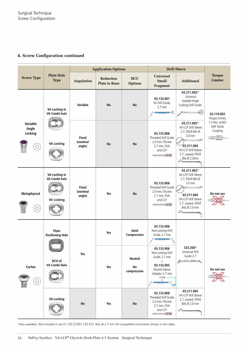
Screw TypePlate Hole
Type
Application Options Drill Sleeve
Torque LimiterAngulation
Reduction Plate to Bone
DCU Options
Universal Small
FragmentAdditional
Variable Angle
Locking
VA Locking in VA Combi hole
VA Locking
Variable No No
03.133.007VA Drill Guide,
2.7 mm
03.211.002* Universal
Variable Angle Locking Drill Guide
03.110.002Torque Limiter, 1.2 Nm, w/AO/
ASIF Quick Coupling
Fixed (nominal
angle)No No
03.133.008Threaded Drill Guide
2.0 mm, f/Screw 2.7 mm, f/VA
and LCP
03.211.002* VA-LCP Drill Sleeve
2.7, f/Drill Bits Ø 2.0 mm
03.211.004VA-LCP Drill Sleeve 2.7, coaxial, f/Drill
Bits Ø 2.0mm
Metaphyseal
VA Locking in VA Combi hole
VA Locking
Fixed (nominal
angle)Yes No
03.133.008Threaded Drill Guide
2.0 mm, f/Screw 2.7 mm, f/VA
and LCP
03.211.002*VA-LCP Drill Sleeve 2.7, f/Drill Bits Ø
2.0 mm
03.211.004VA-LCP Drill Sleeve 2.7, coaxial, f/Drill
Bits Ø 2.0 mm
Do not use
Cortex
Plate Positioning Hole
DCU of VA Combi Hole
Yes
YesAxial
Compression
03.133.006Non-Locking Drill Guide, 2.7 mm
323.260*Universal Drill
Guide 2.7
Do not useYes
Neutral
No compression
03.133.006Non-Locking Drill Guide, 2.7 mm
+ 03.133.005
Neutral Sleeve Adapter, 2.7 mm
+
VA LockingNo Yes No
03.133.008Threaded Drill Guide
2.0 mm, f/Screw 2.7 mm, f/VA
and LCP
03.211.004VA-LCP Drill Sleeve 2.7, coaxial, f/Drill
Bits Ø 2.0 mm
* Also available. Not included in set 01.133.273/01.133.473. Not all 2.7 mm VA compatible instruments shown in this table.
8. Screw Confi guration continued
VA-LCP® Clavicle Hook Plate 2.7 System Surgical Technique DePuy Synthes 23
9. Screw Insertion – 2.7 mm Cortex Screws
Screw Hole Preparation
Instruments
03.133.005 Neutral Sleeve Adapter 2.7 mm, f/Non-Locking Drill Guide 2.7 mm
03.133.006 Non-Locking Drill Guide, 2.7 mm
03.133.100* Drill Bit Ø 2.0 mm, QC, L 110 mm, Calibration 30 mm
323.260† Universal Drill Guide 2.7
310.534†‡ Drill Bit Ø 2.0 mm, w/marking, L 110/85 mm, 2-fl ute, f/Quick Coupl.
323.062†‡ Drill Bit Ø 2.0 mm, w/double marking, L 140/115 mm, 3-fl ute, f/Quick Coupl.
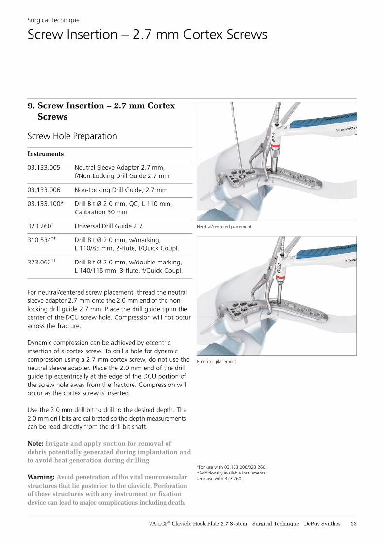
For neutral/centered screw placement, thread the neutral sleeve adaptor 2.7 mm onto the 2.0 mm end of the non-locking drill guide 2.7 mm. Place the drill guide tip in the center of the DCU screw hole. Compression will not occur across the fracture.
Dynamic compression can be achieved by eccentric insertion of a cortex screw. To drill a hole for dynamic compression using a 2.7 mm cortex screw, do not use the neutral sleeve adapter. Place the 2.0 mm end of the drill guide tip eccentrically at the edge of the DCU portion of the screw hole away from the fracture. Compression will occur as the cortex screw is inserted.
Use the 2.0 mm drill bit to drill to the desired depth. The 2.0 mm drill bits are calibrated so the depth measurements can be read directly from the drill bit shaft.
Note: Irrigate and apply suction for removal of debris potentially generated during implantation and to avoid heat generation during drilling.
Warning: Avoid penetration of the vital neurovascular structures that lie posterior to the clavicle. Perforation of these structures with any instrument or fi xation device can lead to major complications including death.
Surgical Technique
Screw Insertion – 2.7 mm Cortex Screws
*For use with 03.133.006/323.260.†Additionally available instruments.‡For use with 323.260.
Neutral/centered placement
Eccentric placement
24 DePuy Synthes VA-LCP® Clavicle Hook Plate 2.7 System Surgical Technique
9. Screw Insertion – 2.7 mm Cortex Screws continued
Hole Depth Measurement
Instruments
03.133.080 Depth Gauge 2.7/3.5 mm, 0 to 60 mm
03.111.005 Depth Gauge f/Screws Ø 2.0 to 2.7 mm, measuring range up to 40 mm
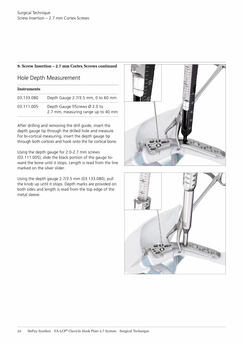
After drilling and removing the drill guide, insert the depth gauge tip through the drilled hole and measure. For bi-cortical measuring, insert the depth gauge tip through both cortices and hook onto the far cortical bone.
Using the depth gauge for 2.0-2.7 mm screws (03.111.005), slide the black portion of the gauge to-ward the bone until it stops. Length is read from the line marked on the silver slider.
Using the depth gauge 2.7/3.5 mm (03.133.080), pull the knob up until it stops. Depth marks are provided on both sides and length is read from the top edge of the metal sleeve.
Surgical TechniqueScrew Insertion – 2.7 mm Cortex Screws
VA-LCP® Clavicle Hook Plate 2.7 System Surgical Technique DePuy Synthes 25
Surgical TechniqueScrew Insertion – 2.7 mm Cortex Screws
9. Screw Insertion – 2.7 mm Cortex Screws continued
Screw Insertion
Instruments
03.133.150 Screwdriver Handle, Universal
314.467 Screwdriver Shaft, StarDrive™ T8, self-holding
314.453 Screwdriver Shaft StarDrive™ 2.4, short, self-holding, f/Quick Coupling
311.260* Tap f/Cortex Screws, Ø 2.7 mm, L 100/33 mm
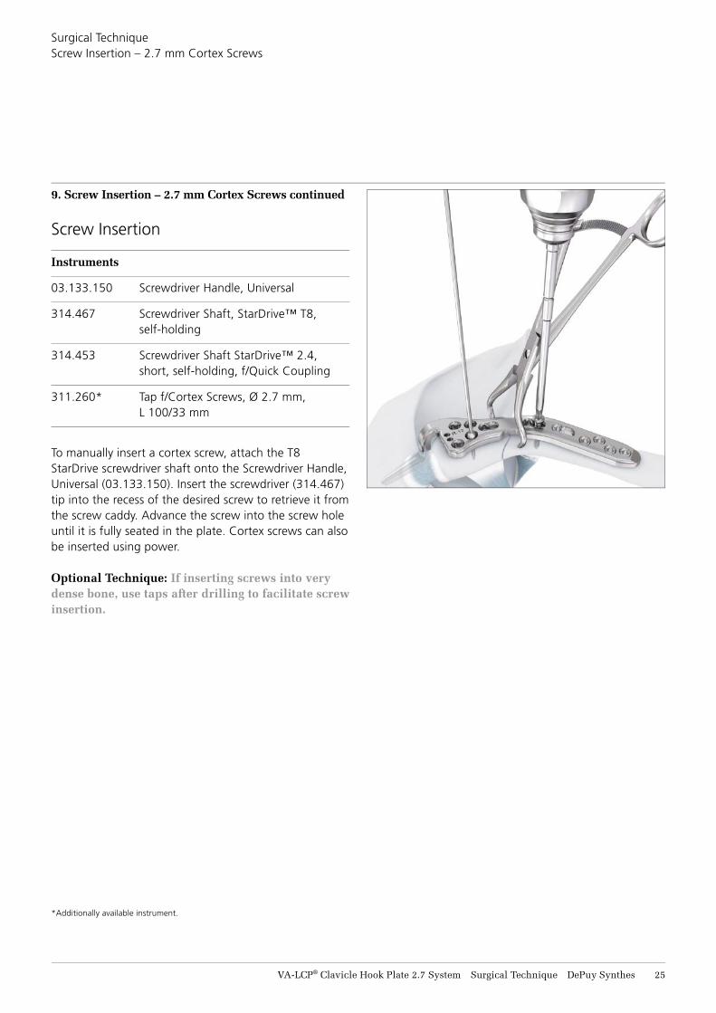
To manually insert a cortex screw, attach the T8 StarDrive screwdriver shaft onto the Screwdriver Handle, Universal (03.133.150). Insert the screwdriver (314.467) tip into the recess of the desired screw to retrieve it from the screw caddy. Advance the screw into the screw hole until it is fully seated in the plate. Cortex screws can also be inserted using power.
Optional Technique: If inserting screws into very dense bone, use taps after drilling to facilitate screw insertion.
*Additionally available instrument.
26 DePuy Synthes VA-LCP® Clavicle Hook Plate 2.7 System Surgical Technique
10. Screw Insertion – 2.7 mm VA Locking Screws and Metaphyseal Screws
Screw Hole Preparation
Instruments – Nominal Angle Drilling
03.133.008 Threaded Drill Guide 2.0 mm, f/Screw 2.7 mm, f/VA and LCP (Figure 3)
03.211.004 VA-LCP Drill Sleeve 2.7, coaxial, f/Drill Bits Ø 2.0 mm (Figure 4)
03.133.100* Drill Bit Ø 2.0 mm, QC, L 110 mm, Calibration 30mm
314.467 Screwdriver Shaft, StarDrive™ T8, self-holding
314.453 Screwdriver Shaft StarDrive™ 2.4, short, self-holding, f/Quick Coupling
03.211.002† VA-LCP Drill Sleeve 2.7, f/Drill Bits Ø 2.0 mm
310.534†‡ Drill Bit Ø 2.0 mm, w/marking, L 110/85 mm, 2-flute, f/Quick Coupl.
323.062†‡ Drill Bit Ø 2.0 mm, w/double marking, L 140/115 mm, 3-flute, f/Quick Coupl.
Precaution: Nominal screw angle is determined by plate design and screw length. If the plate is contoured and/or a screw longer than 40 mm is selected, take care to ensure that screws do not collide with one another. The use of image intensification is recommended.
Warning: Avoid penetration of the vital neurovascular structures that lie posterior to the clavicle. Perforation of these structures with any instrument or fixationdevice can lead to major complications including death.
Surgical Technique
Screw Insertion – 2.7 mm VA Locking Screws and Metaphyseal Screws
* For use with 03.133.008 or 03.211.004. Depth marks on drill bit do not correspond to drill guide 03.211.004.
†Additionally available instruments.‡For use with 03.211.002. Mates with scale on 03.211.002.
VA-LCP® Clavicle Hook Plate 2.7 System Surgical Technique DePuy Synthes 27
Surgical Technique Screw Insertion – 2.7 mm VA Locking Screws and Metaphyseal Screws
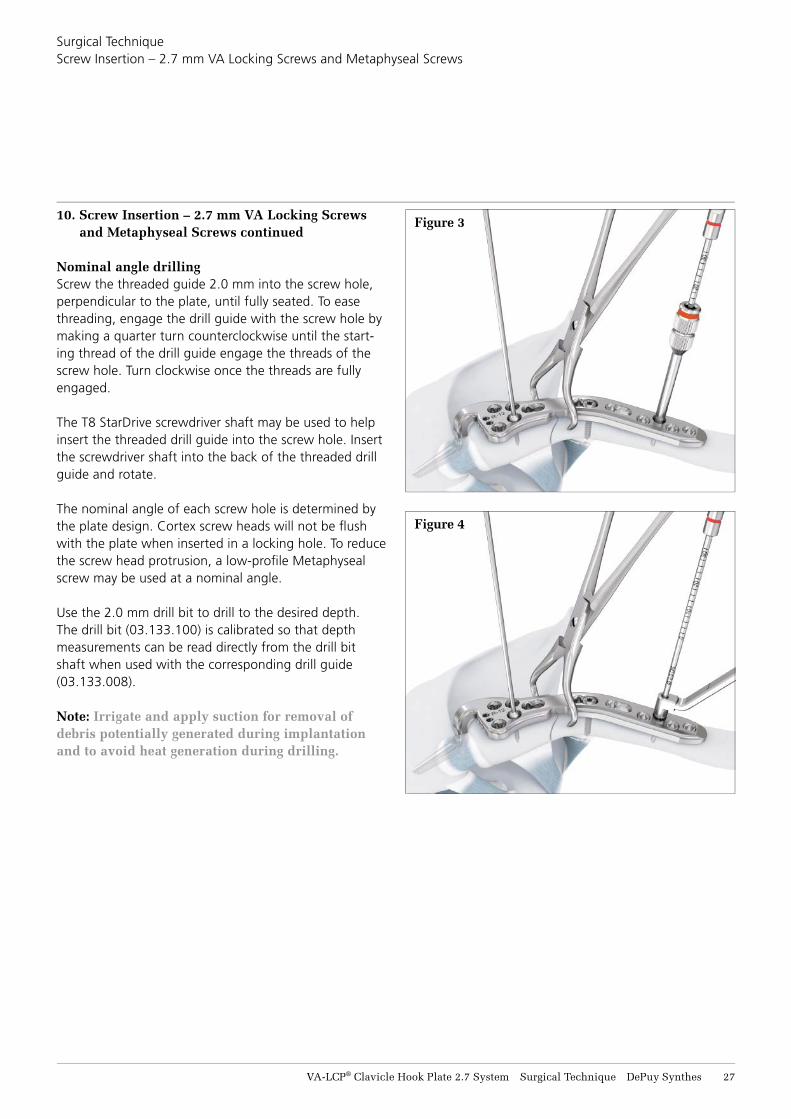
10. Screw Insertion – 2.7 mm VA Locking Screws and Metaphyseal Screws continued
Nominal angle drilling Screw the threaded guide 2.0 mm into the screw hole, perpendicular to the plate, until fully seated. To ease threading, engage the drill guide with the screw hole by making a quarter turn counterclockwise until the start-ing thread of the drill guide engage the threads of the screw hole. Turn clockwise once the threads are fully engaged.
The T8 StarDrive screwdriver shaft may be used to help insert the threaded drill guide into the screw hole. Insert the screwdriver shaft into the back of the threaded drill guide and rotate.
The nominal angle of each screw hole is determined by the plate design. Cortex screw heads will not be fl ush with the plate when inserted in a locking hole. To reduce the screw head protrusion, a low-profi le Metaphyseal screw may be used at a nominal angle.
Use the 2.0 mm drill bit to drill to the desired depth. The drill bit (03.133.100) is calibrated so that depth measurements can be read directly from the drill bit shaft when used with the corresponding drill guide (03.133.008).
Note: Irrigate and apply suction for removal of debris potentially generated during implantation and to avoid heat generation during drilling.
Figure 3
Figure 4
28 DePuy Synthes VA-LCP® Clavicle Hook Plate 2.7 System Surgical Technique
Surgical Technique Screw Insertion – 2.7 mm VA Locking Screws and Metaphyseal Screws
10. Screw Insertion – 2.7 mm VA Locking Screws and Metaphyseal Screws continued
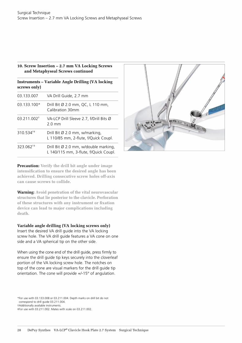
Instruments – Variable Angle Drilling (VA locking screws only)
03.133.007 VA Drill Guide, 2.7 mm
03.133.100* Drill Bit Ø 2.0 mm, QC, L 110 mm, Calibration 30mm
03.211.002† VA-LCP Drill Sleeve 2.7, f/Drill Bits Ø 2.0 mm
310.534†‡ Drill Bit Ø 2.0 mm, w/marking, L 110/85 mm, 2-fl ute, f/Quick Coupl.
323.062†‡ Drill Bit Ø 2.0 mm, w/double marking, L 140/115 mm, 3-fl ute, f/Quick Coupl.
Precaution: Verify the drill bit angle under image intensifi cation to ensure the desired angle has been achieved. Drilling consecutive screw holes off-axis can cause screws to collide.
Warning: Avoid penetration of the vital neurovascular structures that lie posterior to the clavicle. Perforation of these structures with any instrument or fi xation device can lead to major complications including death.
Variable angle drilling (VA locking screws only)Insert the desired VA drill guide into the VA locking screw hole. The VA drill guide features a VA cone on one side and a VA spherical tip on the other side.
When using the cone end of the drill guide, press fi rmly to ensure the drill guide tip keys securely into the cloverleaf portion of the VA locking screw hole. The notches on top of the cone are visual markers for the drill guide tip orientation. The cone will provide +/-15° of angulation.
* For use with 03.133.008 or 03.211.004. Depth marks on drill bit do not correspond to drill guide 03.211.004.
†Additionally available instruments.‡For use with 03.211.002. Mates with scale on 03.211.002.

VA-LCP® Clavicle Hook Plate 2.7 System Surgical Technique DePuy Synthes 29
10. Screw Insertion – 2.7 mm VA Locking Screws and Metaphyseal Screws continued
When using the spherical tip end for freehand drilling, gently press the instrument into the VA hole. The lip portion of the spherical tip end engages with the VA locking hole to provide tactile feedback of the angulation. Continue to provide light pressure while holding the drill guide at the desired angle. The spherical tip end of the drill guide provides freedom to choose angulation. To ensure a precise 15° angulation, use the cone end of the Variable Angle Drill Guide.
Reminder: Metaphyseal screws can only be inserted in VA locking holes at the nominal angle.
Note: Irrigate and apply suction for removal of debris potentially generated during implantation and to avoid heat generation during drilling.
Hole Depth Measurement
Instruments
03.111.005 Depth Gauge f/Screws Ø 2.0 to 2.7 mm, measuring range up to 40 mm
03.133.080 Depth Gauge 2.7/3.5 mm, 0 to 60 mm
See Hole Depth Measurement section on page 24 for instructions on how to measure screw hole depth.
Important: If using the depth gauge 2.7/3.5 mm (03.133.080) for 2.7 mm VA locking screws, subtract 2 mm from the indicated length on the depth gauge to obtain the correct screw length. The depth gauge for 2.0-2.7 mm screws (03.111.005) does not require subtraction from the reading.
Surgical Technique Screw Insertion – 2.7 mm VA Locking Screws and Metaphyseal Screws
30 DePuy Synthes VA-LCP® Clavicle Hook Plate 2.7 System Surgical Technique
Surgical Technique Screw Insertion – 2.7 mm VA Locking Screws and Metaphyseal Screws
10. Screw Insertion – 2.7 mm VA Locking Screws and Metaphyseal Screws continued
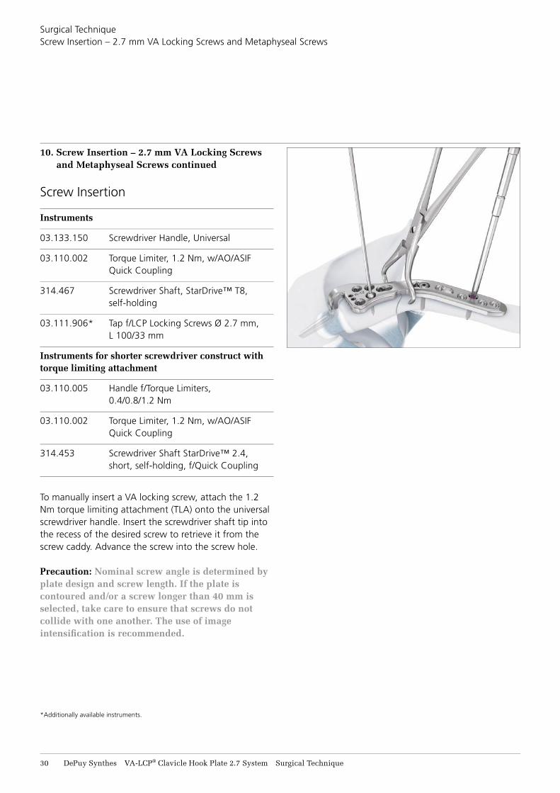
Screw Insertion
Instruments
03.133.150 Screwdriver Handle, Universal
03.110.002 Torque Limiter, 1.2 Nm, w/AO/ASIF Quick Coupling
314.467 Screwdriver Shaft, StarDrive™ T8, self-holding
03.111.906* Tap f/LCP Locking Screws Ø 2.7 mm, L 100/33 mm
Instruments for shorter screwdriver construct with torque limiting attachment
03.110.005 Handle f/Torque Limiters, 0.4/0.8/1.2 Nm
03.110.002 Torque Limiter, 1.2 Nm, w/AO/ASIF Quick Coupling
314.453 Screwdriver Shaft StarDrive™ 2.4, short, self-holding, f/Quick Coupling
To manually insert a VA locking screw, attach the 1.2 Nm torque limiting attachment (TLA) onto the universal screwdriver handle. Insert the screwdriver shaft tip into the recess of the desired screw to retrieve it from the screw caddy. Advance the screw into the screw hole.
Precaution: Nominal screw angle is determined by plate design and screw length. If the plate is contoured and/or a screw longer than 40 mm is selected, take care to ensure that screws do not collide with one another. The use of image intensifi cation is recommended.
*Additionally available instruments.
VA-LCP® Clavicle Hook Plate 2.7 System Surgical Technique DePuy Synthes 31
Surgical Technique Screw Insertion – 2.7 mm VA Locking Screws and Metaphyseal Screws
10. Screw Insertion – 2.7 mm VA Locking Screws and Metaphyseal Screws continued
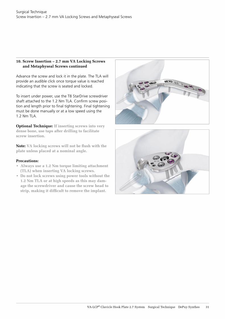
Advance the screw and lock it in the plate. The TLA will provide an audible click once torque value is reached indicating that the screw is seated and locked.
To insert under power, use the T8 StarDrive screwdriver shaft attached to the 1.2 Nm TLA. Confi rm screw posi-tion and length prior to fi nal tightening. Final tightening must be done manually or at a low speed using the 1.2 Nm TLA.
Optional Technique: If inserting screws into very dense bone, use taps after drilling to facilitate screw insertion.
Note: VA locking screws will not be fl ush with the plate unless placed at a nominal angle.
Precautions: • Always use a 1.2 Nm torque limiting attachment
(TLA) when inserting VA locking screws.• Do not lock screws using power tools without the
1.2 Nm TLA or at high speeds as this may dam-age the screwdriver and cause the screw head to strip, making it diffi cult to remove the implant.
32 DePuy Synthes VA-LCP® Clavicle Hook Plate 2.7 System Surgical Technique
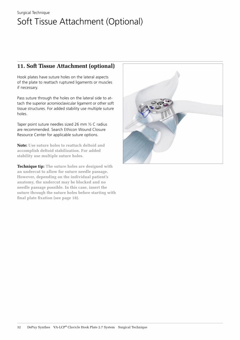
11. Soft Tissue Attachment (optional)
Hook plates have suture holes on the lateral aspects of the plate to reattach ruptured ligaments or muscles if necessary.
Pass suture through the holes on the lateral side to at-tach the superior acromioclavicular ligament or other soft tissue structures. For added stability use multiple suture holes.
Taper point suture needles sized 26 mm ½ C radius are recommended. Search Ethicon Wound Closure Resource Center for applicable suture options.
Note: Use suture holes to reattach deltoid and accomplish deltoid stabilization. For added stability use multiple suture holes.
Technique tip: The suture holes are designed with an undercut to allow for suture needle passage. However, depending on the individual patient’s anatomy, the undercut may be blocked and no needle passage possible. In this case, insert the suture through the suture holes before starting with fi nal plate fi xation (see page 18).
Surgical Technique
Soft Tissue Attachment (Optional)
VA-LCP® Clavicle Hook Plate 2.7 System Surgical Technique DePuy Synthes 33
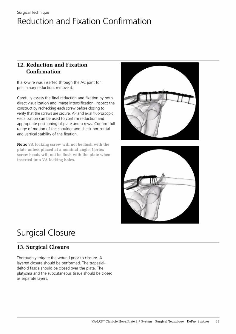
12. Reduction and Fixation Confirmation
If a K-wire was inserted through the AC joint for preliminary reduction, remove it.
Carefully assess the final reduction and fixation by both direct visualization and image intensification. Inspect the construct by rechecking each screw before closing to verify that the screws are secure. AP and axial fluoroscopic visualization can be used to confirm reduction and appropriate positioning of plate and screws. Confirm full range of motion of the shoulder and check horizontal and vertical stability of the fixation.
Note: VA locking screw will not be flush with the plate unless placed at a nominal angle. Cortex screw heads will not be flush with the plate when inserted into VA locking holes.
Surgical Technique
Reduction and Fixation Confirmation
Surgical Closure
13. Surgical Closure
Thoroughly irrigate the wound prior to closure. A layered closure should be performed. The trapezial- deltoid fascia should be closed over the plate. The platysma and the subcutaneous tissue should be closed as separate layers.
34 DePuy Synthes VA-LCP® Clavicle Hook Plate 2.7 System Surgical Technique
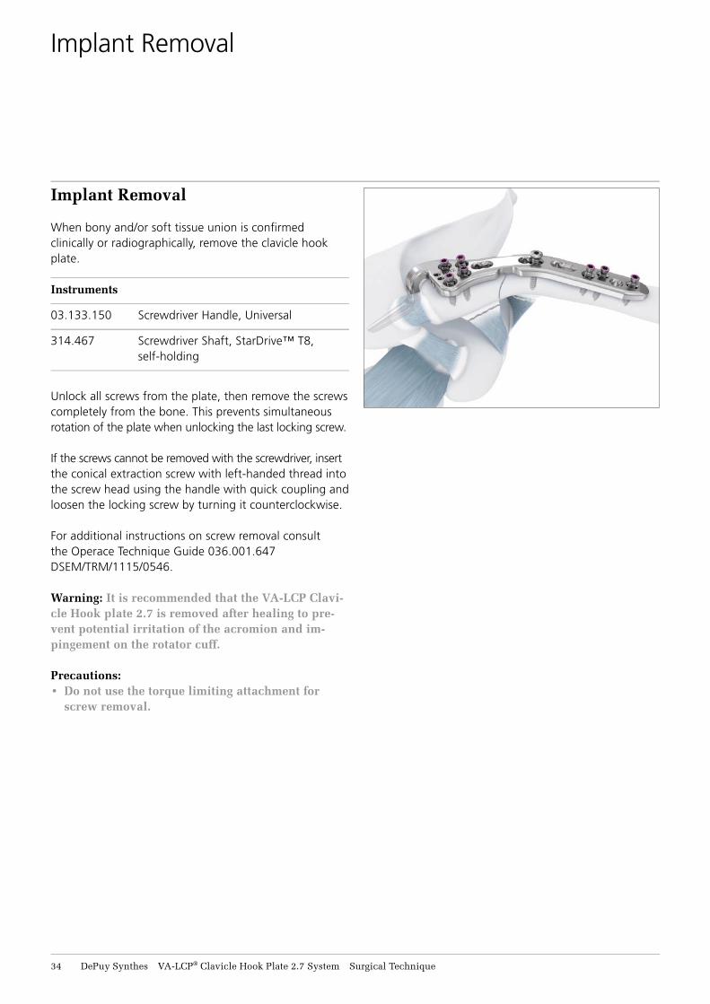
Implant Removal
When bony and/or soft tissue union is confi rmed clinically or radiographically, remove the clavicle hook plate.
Instruments
03.133.150 Screwdriver Handle, Universal
314.467 Screwdriver Shaft, StarDrive™ T8, self-holding
Unlock all screws from the plate, then remove the screws completely from the bone. This prevents simultaneous rotation of the plate when unlocking the last locking screw.
If the screws cannot be removed with the screwdriver, insert the conical extraction screw with left-handed thread into the screw head using the handle with quick coupling and loosen the locking screw by turning it counterclockwise.
For additional instructions on screw removal consult the Operace Technique Guide 036.001.647 DSEM/TRM/1115/0546.
Warning: It is recommended that the VA-LCP Clavi-cle Hook plate 2.7 is removed after healing to pre-vent potential irritation of the acromion and im-pingement on the rotator cuff.
Precautions: • Do not use the torque limiting attachment for
screw removal.
Implant Removal
VA-LCP® Clavicle Hook Plate 2.7 System Surgical Technique DePuy Synthes 35
Stainless Steel Titanium
Plate Shape
Hook Depth
Left/Right
02.112.810 04.112.810 Long 9 mm Left
02.112.811 04.112.811 Long 9 mm Right (shown)
02.112.812 04.112.812 Long 12 mm Left
02.112.813 04.112.813 Long 12 mm Right
02.112.814 04.112.814 Long 15 mm Left
02.112.815 04.112.815 Long 15 mm Right
02.112.820 04.112.820 Short 9 mm Left
02.112.821 04.112.821 Short 9 mm Right (shown)
02.112.822 04.112.822 Short 12 mm Left
02.112.823 04.112.823 Short 12 mm Right
02.112.824 04.112.824 Short 15 mm Left
02.112.825 04.112.825 Short 15 mm Right
02.112.910 04.112.910 Button 9 mm Left
02.112.911 04.112.911 Button 9 mm Right (shown)
02.112.912 04.112.912 Button 12 mm Left
02.112.913 04.112.913 Button 12 mm Right
02.112.914 04.112.914 Button 15 mm Left
02.112.915 04.112.915 Button 15 mm Right
Product Information
Implants
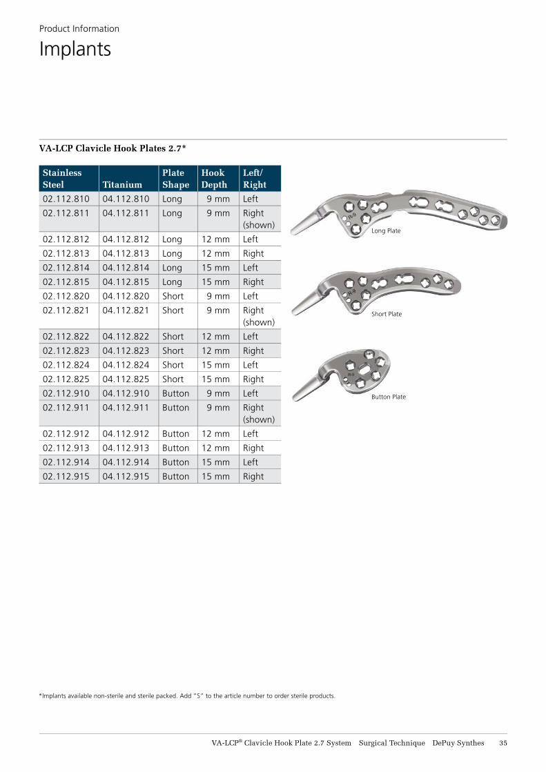
VA-LCP Clavicle Hook Plates 2.7*
Long Plate
Short Plate
Button Plate
*Implants available non-sterile and sterile packed. Add “S” to the article number to order sterile products.
36 DePuy Synthes VA-LCP® Clavicle Hook Plate 2.7 System Surgical Technique
Product Information Implants
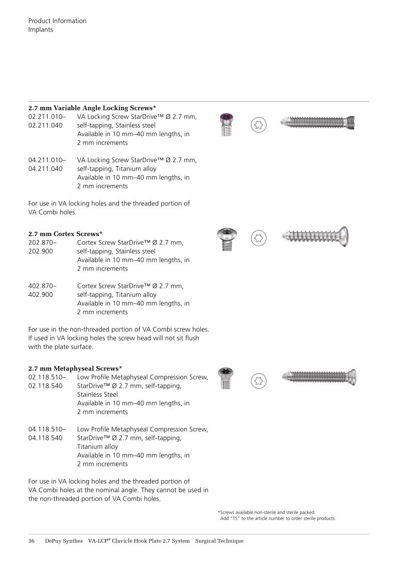
2.7 mm Variable Angle Locking Screws*02.211.010– VA Locking Screw StarDrive™ Ø 2.7 mm, 02.211.040 self-tapping, Stainless steel Available in 10 mm–40 mm lengths, in
2 mm increments
04.211.010– VA Locking Screw StarDrive™ Ø 2.7 mm, 04.211.040 self-tapping, Titanium alloy Available in 10 mm–40 mm lengths, in
2 mm increments
For use in VA locking holes and the threaded portion of VA Combi holes.
2.7 mm Cortex Screws*202.870– Cortex Screw StarDrive™ Ø 2.7 mm, 202.900 self-tapping, Stainless steel Available in 10 mm–40 mm lengths, in
2 mm increments
402.870– Cortex Screw StarDrive™ Ø 2.7 mm, 402.900 self-tapping, Titanium alloy Available in 10 mm–40 mm lengths, in
2 mm increments
For use in the non-threaded portion of VA Combi screw holes. If used in VA locking holes the screw head will not sit fl ush with the plate surface.
2.7 mm Metaphyseal Screws*02.118.510– Low Profi le Metaphyseal Compression Screw, 02.118.540 StarDrive™ Ø 2.7 mm, self-tapping, Stainless Steel Available in 10 mm–40 mm lengths, in
2 mm increments
04.118.510– Low Profi le Metaphyseal Compression Screw, 04.118.540 StarDrive™ Ø 2.7 mm, self-tapping, Titanium alloy Available in 10 mm–40 mm lengths, in
2 mm increments
For use in VA locking holes and the threaded portion of VA Combi holes at the nominal angle. They cannot be used in the non-threaded portion of VA Combi holes.
* Screws available non-sterile and sterile packed. Add “TS” to the article number to order sterile products.
VA-LCP® Clavicle Hook Plate 2.7 System Surgical Technique DePuy Synthes 37
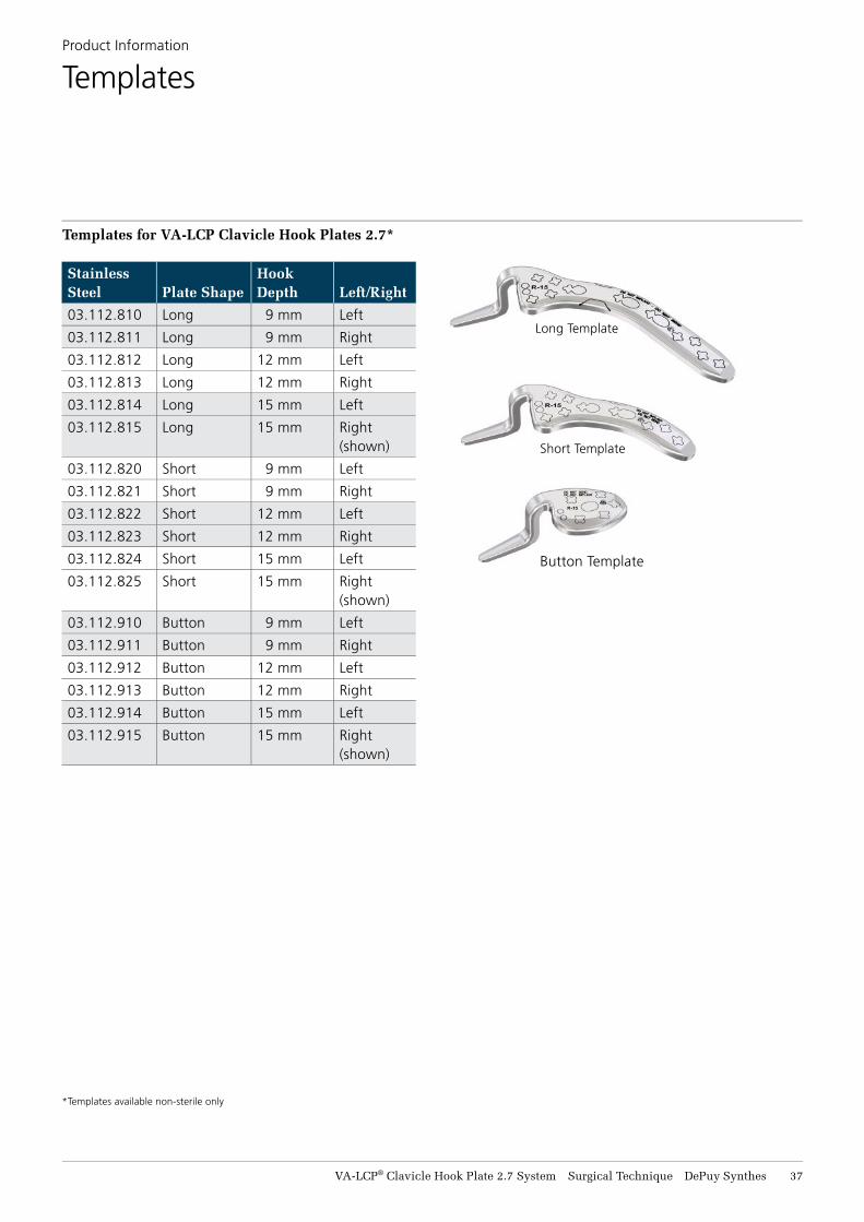
Templates for VA-LCP Clavicle Hook Plates 2.7*
Product Information
Templates
Stainless Steel Plate Shape
Hook Depth Left/Right
03.112.810 Long 9 mm Left
03.112.811 Long 9 mm Right
03.112.812 Long 12 mm Left
03.112.813 Long 12 mm Right
03.112.814 Long 15 mm Left
03.112.815 Long 15 mm Right (shown)
03.112.820 Short 9 mm Left
03.112.821 Short 9 mm Right
03.112.822 Short 12 mm Left
03.112.823 Short 12 mm Right
03.112.824 Short 15 mm Left
03.112.825 Short 15 mm Right (shown)
03.112.910 Button 9 mm Left
03.112.911 Button 9 mm Right
03.112.912 Button 12 mm Left
03.112.913 Button 12 mm Right
03.112.914 Button 15 mm Left
03.112.915 Button 15 mm Right (shown)
*Templates available non-sterile only
Long Template
Short Template
Button Template

38 DePuy Synthes VA-LCP® Clavicle Hook Plate 2.7 System Surgical Technique
03.110.002 Torque Limiter, 1.2 Nm, w/AO/ASIF Quick Coupling
03.110.005 Handle f/Torque Limiters, 0.4/0.8/1.2 Nm
03.111.005 Depth Gauge f/Screws Ø 2.0 to 2.7 mm, measuring range up to 40 mm
03.133.005 Neutral Sleeve Adapter 2.7 mm, f/Non-Locking Drill Guide 2.7 mm
03.133.006 Non-Locking Drill Guide, 2.7 mm
03.133.007 VA Drill Guide, 2.7 mm
03.133.080 Depth Gauge 2.7/3.5 mm, 0 to 60 mm
03.133.008 Threaded Drill Guide 2.0 mm, f/Screw 2.7 mm, f/VA and LCP
Product Information
Instruments
VA-LCP® Clavicle Hook Plate 2.7 System Surgical Technique DePuy Synthes 39
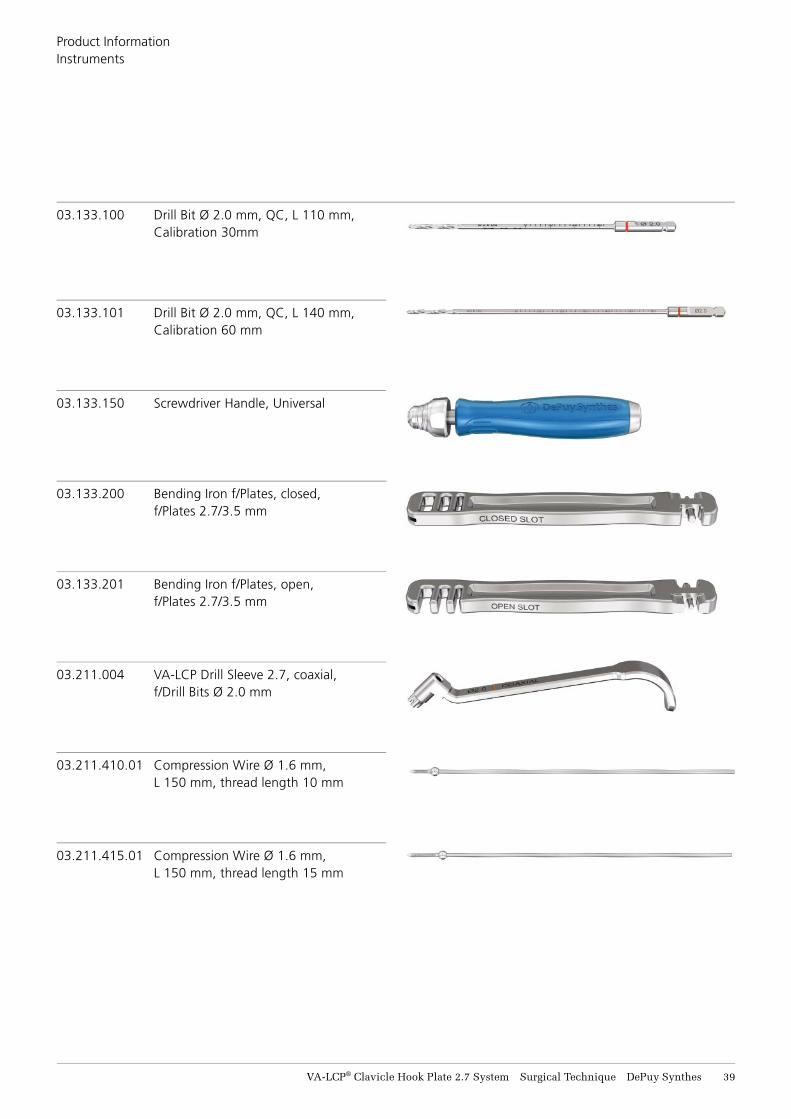
03.133.101 Drill Bit Ø 2.0 mm, QC, L 140 mm, Calibration 60 mm
03.133.150 Screwdriver Handle, Universal
03.133.200 Bending Iron f/Plates, closed, f/Plates 2.7/3.5 mm
03.133.201 Bending Iron f/Plates, open, f/Plates 2.7/3.5 mm
03.211.004 VA-LCP Drill Sleeve 2.7, coaxial, f/Drill Bits Ø 2.0 mm
03.211.410.01 Compression Wire Ø 1.6 mm, L 150 mm, thread length 10 mm
03.211.415.01 Compression Wire Ø 1.6 mm, L 150 mm, thread length 15 mm
03.133.100 Drill Bit Ø 2.0 mm, QC, L 110 mm, Calibration 30mm
Product Information Instruments
40 DePuy Synthes VA-LCP® Clavicle Hook Plate 2.7 System Surgical Technique
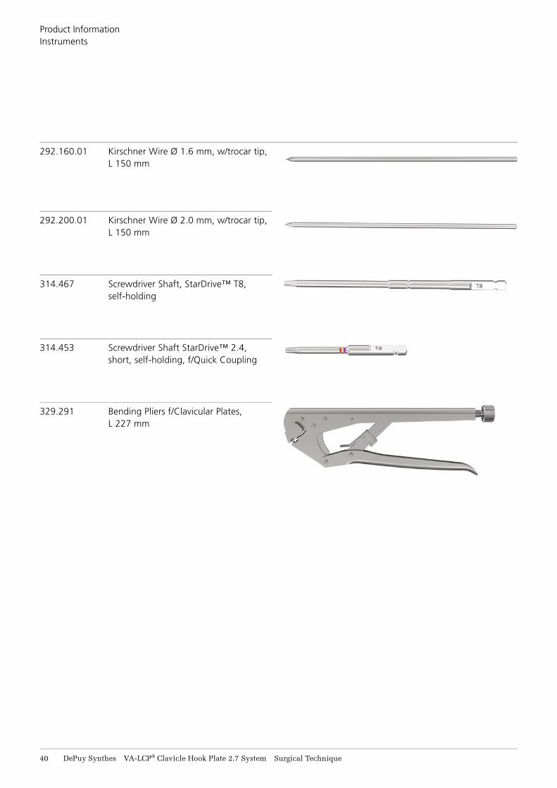
314.467 Screwdriver Shaft, StarDrive™ T8, self-holding
314.453 Screwdriver Shaft StarDrive™ 2.4, short, self-holding, f/Quick Coupling
329.291 Bending Pliers f/Clavicular Plates, L 227 mm
292.160.01 Kirschner Wire Ø 1.6 mm, w/trocar tip, L 150 mm
292.200.01 Kirschner Wire Ø 2.0 mm, w/trocar tip, L 150 mm
Product Information Instruments
VA-LCP® Clavicle Hook Plate 2.7 System Surgical Technique DePuy Synthes 41
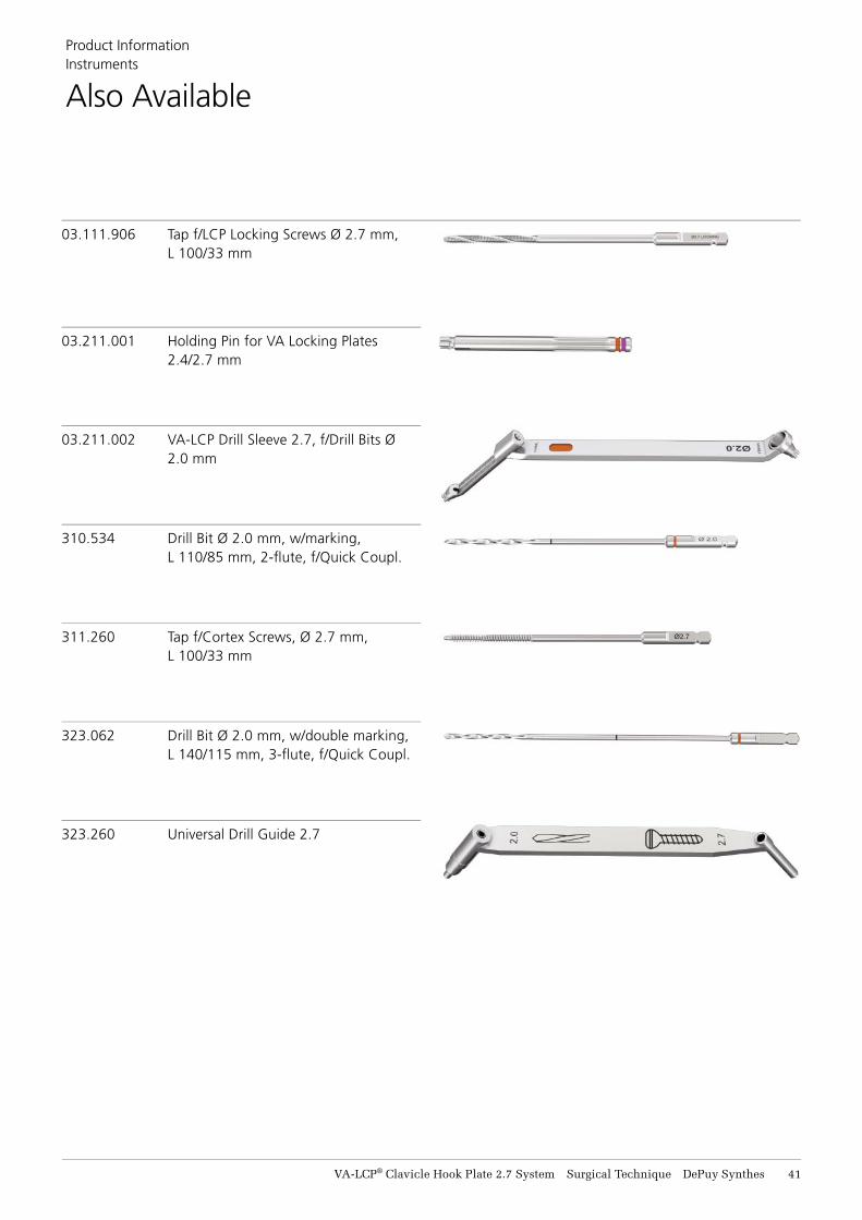
323.062 Drill Bit Ø 2.0 mm, w/double marking, L 140/115 mm, 3-fl ute, f/Quick Coupl.
311.260 Tap f/Cortex Screws, Ø 2.7 mm, L 100/33 mm
03.111.906 Tap f/LCP Locking Screws Ø 2.7 mm, L 100/33 mm
310.534 Drill Bit Ø 2.0 mm, w/marking, L 110/85 mm, 2-fl ute, f/Quick Coupl.
323.260 Universal Drill Guide 2.7
03.211.002 VA-LCP Drill Sleeve 2.7, f/Drill Bits Ø 2.0 mm
03.211.001 Holding Pin for VA Locking Plates 2.4/2.7 mm
Product Information Instruments
Also Available
42 DePuy Synthes VA-LCP® Clavicle Hook Plate 2.7 System Surgical Technique
MRI Safety Information
Torque, Displacement and Image Artifacts according to ASTM F2213-17, ASTM F2052-15 and ASTM F2119-07 (2013)Non-clinical testing of a worst-case scenario in a 3 T Magnetic Resonance Imag-ing (MRI) system did not reveal any relevant torque or displacement of the con-struct for an experimentally measured local spatial gradient of the magnetic field of 3.69 T/m. The largest image artifact extended approximately 138 mm from the construct when scanned using the Gradient Echo (GE). Testing was con-ducted on a 3 T MRI system.
Radio-Frequency-(RF-)induced heating according to ASTM F2182-19Non-clinical electromagnetic and thermal simulations of a worst case scenario lead to temperature rises of 12.1 °C (1.5 T) and 6.0 °C (3 T) under MRI condi-tions using RF Coils (whole body averaged specific absorption rate [SAR] of 2 W/kg for 15 minutes).
Precautions: The above mentioned test relies on non-clinical testing. The actual temperature rise in the patient will depend on a variety of factors beyond the SAR and time of RF application. Thus, it is recommended to pay particular attention to the following points:• It is recommended to thoroughly monitor patients undergoing
MR scanning for perceived temperature and/or pain sensations.• Patients with impaired thermoregulation or temperature sensation
should be excluded from MR scanning procedures.• Generally, it is recommended to use an MRI system with low field
strength in the presence of conductive implants. The employed specific absorption rate (SAR) should be reduced as far as possible.
• Using the ventilation system may further contribute to reduce temperature increase in the body.
Instruments (including templates)MR Safety Information is not applicable to instruments. Instruments are not intended to be used in an MR environment.
MRI Safety Information
68.033.121
68.133.007
60.133.146 60.133.190
VA-LCP® Clavicle Hook Plate 2.7 System Surgical Technique DePuy Synthes 43
Cases & Trays
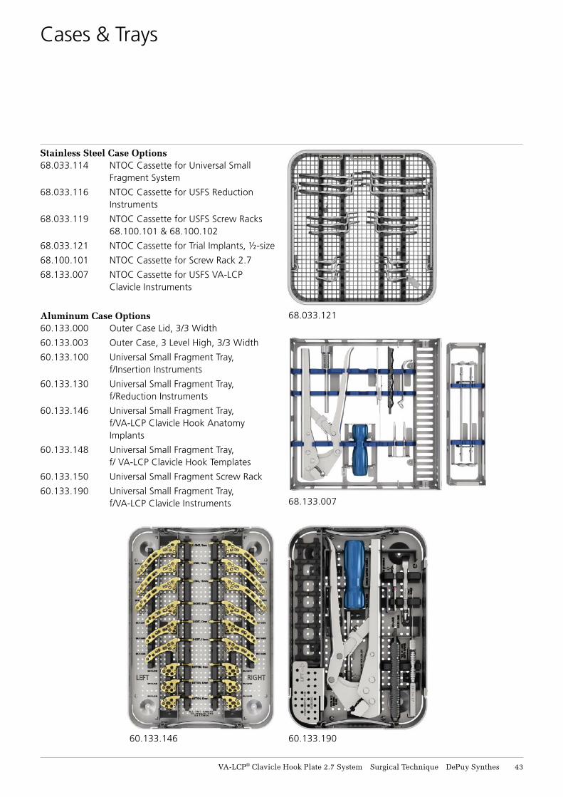
Stainless Steel Case Options 68.033.114 NTOC Cassette for Universal Small
Fragment System
68.033.116 NTOC Cassette for USFS Reduction Instruments
68.033.119 NTOC Cassette for USFS Screw Racks 68.100.101 & 68.100.102
68.033.121 NTOC Cassette for Trial Implants, ½-size
68.100.101 NTOC Cassette for Screw Rack 2.7
68.133.007 NTOC Cassette for USFS VA-LCP Clavicle Instruments
Aluminum Case Options 60.133.000 Outer Case Lid, 3/3 Width
60.133.003 Outer Case, 3 Level High, 3/3 Width
60.133.100 Universal Small Fragment Tray, f/Insertion Instruments
60.133.130 Universal Small Fragment Tray, f/Reduction Instruments
60.133.146 Universal Small Fragment Tray, f/VA-LCP Clavicle Hook Anatomy Implants
60.133.148 Universal Small Fragment Tray, f/ VA-LCP Clavicle Hook Templates
60.133.150 Universal Small Fragment Screw Rack
60.133.190 Universal Small Fragment Tray, f/VA-LCP Clavicle Instruments

Synthes GmbHEimattstrasse 34436 OberdorfSwitzerlandTel: +41 61 965 61 11Fax: +41 61 965 66 00www.depuysynthes.com
For full product details, including warnings and precautions, please consult the Instructions for Use.
Not all products are currently available in all markets.
This publication is not intended for distribution in the USA.
All surgical techniques are available as PDF files at www.depuysynthes.com/ifu ©
DeP
uy S
ynth
es T
raum
a, a
div
isio
n of
Syn
thes
Gm
bH. 2
021.
A
ll rig
hts
rese
rved
. 15
9338
-201
116
SE
_825
568
AC
06
/21


![CASE REPORT Open Access LCP external fixation ......on LCP external fixation Infection (%) Nonunion (%) Kloen [4] 2009 4 Infected nonunion 1 clavicle, 3 tibia 3.5 or 4.5 mm LCP 3 temporary,](https://img.pdfslide.net/doc/110x75/5f721fabc5180773994e074d/case-report-open-access-lcp-external-fixation-on-lcp-external-fixation-infection.jpg)