Embed Size (px)
Citation preview
1. INTRODUCTION
Investigations on fracturing (cracking) processes in shale, specifically crack initiation, -propagation, and -coalescence contribute to the understanding of shale behavior. This is important for stability and deformability problems encountered in civil and mining engineering. It is also very important in the context of hydraulic fracturing for hydrocarbon extraction.
Vaca Muerta shale is a petroleum bearing formation in the Neuquén Basin for which the application of hydraulic fracturing is considered. To provide a basis for understanding the hydraulic fracturing mechanisms in this material, it is necessary to conduct experiments on specimens without hydraulic pressure first, and this is what is presented in this paper.
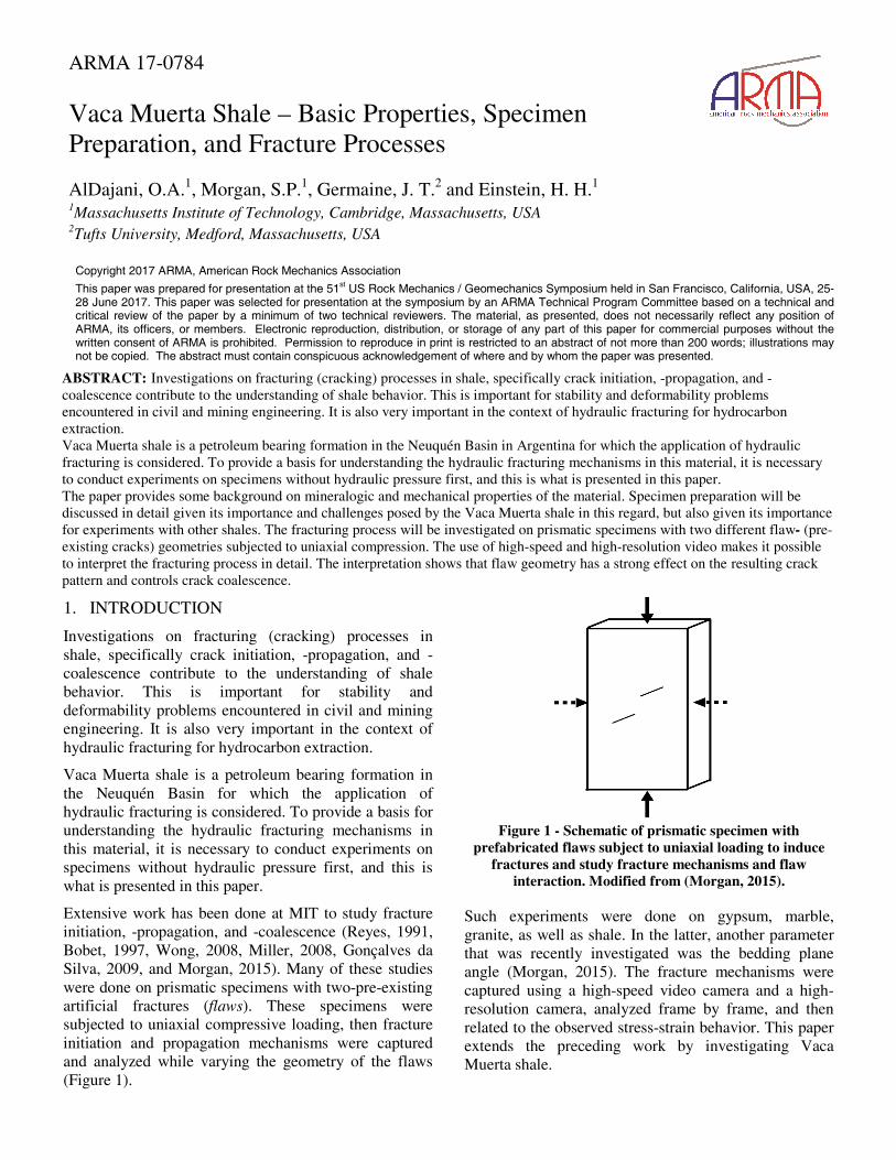
Extensive work has been done at MIT to study fracture initiation, -propagation, and -coalescence (Reyes, 1991, Bobet, 1997, Wong, 2008, Miller, 2008, Gonçalves da Silva, 2009, and Morgan, 2015). Many of these studies were done on prismatic specimens with two-pre-existing artificial fractures (flaws). These specimens were subjected to uniaxial compressive loading, then fracture initiation and propagation mechanisms were captured and analyzed while varying the geometry of the flaws (Figure 1).
Figure 1 - Schematic of prismatic specimen with
prefabricated flaws subject to uniaxial loading to induce fractures and study fracture mechanisms and flaw
interaction. Modified from (Morgan, 2015).
Such experiments were done on gypsum, marble, granite, as well as shale. In the latter, another parameter that was recently investigated was the bedding plane angle (Morgan, 2015). The fracture mechanisms were captured using a high-speed video camera and a high-resolution camera, analyzed frame by frame, and then related to the observed stress-strain behavior. This paper extends the preceding work by investigating Vaca Muerta shale.
ARMA 17-0784 Vaca Muerta Shale – Basic Properties, Specimen Preparation, and Fracture Processes
AlDajani, O.A.1, Morgan, S.P.1, Germaine, J. T.2 and Einstein, H. H.1 1Massachusetts Institute of Technology, Cambridge, Massachusetts, USA 2Tufts University, Medford, Massachusetts, USA
Copyright 2017 ARMA, American Rock Mechanics Association
This paper was prepared for presentation at the 51st US Rock Mechanics / Geomechanics Symposium held in San Francisco, California, USA, 25-28 June 2017. This paper was selected for presentation at the symposium by an ARMA Technical Program Committee based on a technical and critical review of the paper by a minimum of two technical reviewers. The material, as presented, does not necessarily reflect any position of ARMA, its officers, or members. Electronic reproduction, distribution, or storage of any part of this paper for commercial purposes without the written consent of ARMA is prohibited. Permission to reproduce in print is restricted to an abstract of not more than 200 words; illustrations may not be copied. The abstract must contain conspicuous acknowledgement of where and by whom the paper was presented.
ABSTRACT: Investigations on fracturing (cracking) processes in shale, specifically crack initiation, -propagation, and -coalescence contribute to the understanding of shale behavior. This is important for stability and deformability problems encountered in civil and mining engineering. It is also very important in the context of hydraulic fracturing for hydrocarbon extraction. Vaca Muerta shale is a petroleum bearing formation in the Neuquén Basin in Argentina for which the application of hydraulic fracturing is considered. To provide a basis for understanding the hydraulic fracturing mechanisms in this material, it is necessary to conduct experiments on specimens without hydraulic pressure first, and this is what is presented in this paper. The paper provides some background on mineralogic and mechanical properties of the material. Specimen preparation will be discussed in detail given its importance and challenges posed by the Vaca Muerta shale in this regard, but also given its importance for experiments with other shales. The fracturing process will be investigated on prismatic specimens with two different flaw- (pre-existing cracks) geometries subjected to uniaxial compression. The use of high-speed and high-resolution video makes it possible to interpret the fracturing process in detail. The interpretation shows that flaw geometry has a strong effect on the resulting crack pattern and controls crack coalescence.
The paper starts with background information on mineralogic and mechanical properties of the material. Specimen preparation will be discussed in detail given its importance and challenges posed by Vaca Muerta in this regard; this is, however, also very useful for specimen preparation of other shales. The fracturing process will be investigated on prismatic specimens with two different flaw geometries subjected to uniaxial compression. The use of high-speed and high-resolution video makes it possible to interpret the fracturing process in detail. As will be shown, flaw geometry has a strong effect on the resulting crack pattern and controls crack coalescence
2. MATERIAL STUDIED
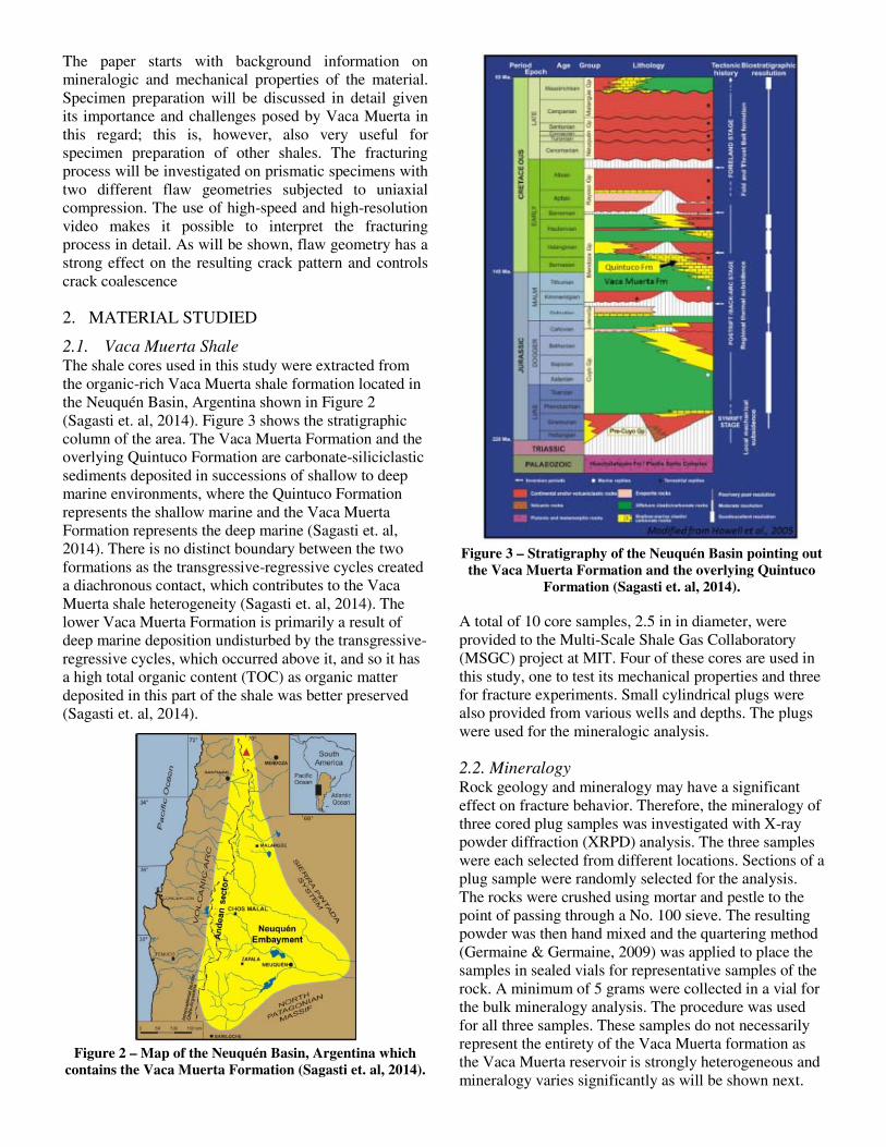
2.1. Vaca Muerta Shale The shale cores used in this study were extracted from the organic-rich Vaca Muerta shale formation located in the Neuquén Basin, Argentina shown in Figure 2 (Sagasti et. al, 2014). Figure 3 shows the stratigraphic column of the area. The Vaca Muerta Formation and the overlying Quintuco Formation are carbonate-siliciclastic sediments deposited in successions of shallow to deep marine environments, where the Quintuco Formation represents the shallow marine and the Vaca Muerta Formation represents the deep marine (Sagasti et. al, 2014). There is no distinct boundary between the two formations as the transgressive-regressive cycles created a diachronous contact, which contributes to the Vaca Muerta shale heterogeneity (Sagasti et. al, 2014). The lower Vaca Muerta Formation is primarily a result of deep marine deposition undisturbed by the transgressive-regressive cycles, which occurred above it, and so it has a high total organic content (TOC) as organic matter deposited in this part of the shale was better preserved (Sagasti et. al, 2014).
Figure 2 – Map of the Neuquén Basin, Argentina which
contains the Vaca Muerta Formation (Sagasti et. al, 2014).
Figure 3 – Stratigraphy of the Neuquén Basin pointing out the Vaca Muerta Formation and the overlying Quintuco
Formation (Sagasti et. al, 2014).
A total of 10 core samples, 2.5 in in diameter, were provided to the Multi-Scale Shale Gas Collaboratory (MSGC) project at MIT. Four of these cores are used in this study, one to test its mechanical properties and three for fracture experiments. Small cylindrical plugs were also provided from various wells and depths. The plugs were used for the mineralogic analysis.
2.2. Mineralogy Rock geology and mineralogy may have a significant effect on fracture behavior. Therefore, the mineralogy of three cored plug samples was investigated with X-ray powder diffraction (XRPD) analysis. The three samples were each selected from different locations. Sections of a plug sample were randomly selected for the analysis. The rocks were crushed using mortar and pestle to the point of passing through a No. 100 sieve. The resulting powder was then hand mixed and the quartering method (Germaine & Germaine, 2009) was applied to place the samples in sealed vials for representative samples of the rock. A minimum of 5 grams were collected in a vial for the bulk mineralogy analysis. The procedure was used for all three samples. These samples do not necessarily represent the entirety of the Vaca Muerta formation as the Vaca Muerta reservoir is strongly heterogeneous and mineralogy varies significantly as will be shown next.
The results of the bulk mineralogy analysis for various Vaca Muerta shale samples are listed in Table 1.
Table 1. Bulk mineralogy for various Vaca Muerta shale samples measured with XRPD, highlighting quartz, carbonate* (calcite + dolomite), and clay** (chlorite, illite+illite/smectite-mixed layers, kaolinite) mineral contents.
Sample VM-X3 VM-X4 VM-X5 Quartz 82.6 37.6 25.7 K-Feldspar 2.9 1.8 0 Plagioclase 4.8 13.4 9.6 Calcite 0.2 15.1 14.4 Dolomite 0.3 1.2 1.5 Halite 0.8 0.1 0.2 Anatase 0 0.1 0.1 Apatite 0.5 1.5 0.9 Pyrite 0.2 2.6 1.3 Chlorite 0.4 0.7 5.6 Muscovite 0 3.6 0 I+I/S-ML 3.6 20.9 40.6 Kaolinite 0 0.6 0 Hematite 3.7 0 0.1 Marcasite 0 0.7 0.1 Carbonate* 0.5 16.3 15.9 Clay** 4 22.2 46.2
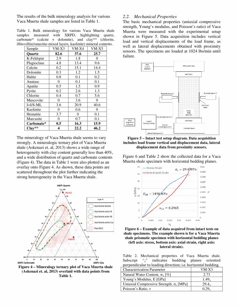
The mineralogy of Vaca Muerta shale seems to vary strongly. A mineralogic ternary plot of Vaca Muerta shale (Askenazi et. al, 2013) shows a wide range of heterogeneity with clay content generally less than 40%, and a wide distribution of quartz and carbonate contents (Figure 4). The data in Table 1 were also plotted as an overlay onto Figure 4. As shown, these data points are scattered throughout the plot further indicating the strong heterogeneity in the Vaca Muerta shale.
Figure 4 – Mineralogy ternary plot of Vaca Muerta shale
(Askenazi et. al, 2013) overlaid with data points from Table 1.
2.2. Mechanical Properties The basic mechanical properties (uniaxial compressive strength, Young’s modulus, and Poisson’s ratio) of Vaca Muerta were measured with the experimental setup shown in Figure 5. Data acquisition includes vertical load and vertical displacements of the load frame, as well as lateral displacements obtained with proximity sensors. The specimens are loaded at 1024 lbs/min until failure.
Figure 5 – Intact test setup diagram. Data acquisition
includes load frame vertical and displacement data, lateral displacement data from proximity sensors.
Figure 6 and Table 2 show the collected data for a Vaca Muerta shale specimen with horizontal bedding planes.
Figure 6 – Example of data acquired from intact tests on
shale specimens. The example shown is for a Vaca Muerta shale prismatic specimen with horizontal bedding planes
(left axis: stress, bottom axis: axial strain, right axis: lateral strain).
Table 2. Mechanical properties of Vaca Muerta shale. Subscript “⊥” indicates bedding planes oriented perpendicular to loading direction; i.e. horizontal bedding. Characterization Parameter VM-X3 Natural Water Content, wc [%] 2.73 Young’s Modulus, E [GPa] 1.49⊥ Uniaxial Compressive Strength, σc [MPa] 29.4⊥ Poisson’s Ratio, ν 0.29⊥
3. SPECIMEN PREPARATION
The objective of the specimen preparation techniques is to produce a prismatic specimen with a pair of pre-existing flaws shown in Figure 7, causing as little mechanical or chemical disturbance as possible to the natural state of the rock throughout the preparation process.
Figure 7 – Objective of specimen preparation is to produce
a prismatic shale specimen with double flaws with the dimensions shown in the figure (Morgan, 2015).
3.1. Cutting Prismatic Specimens The Vaca Muerta cores are 2.5 in diameter cylinders and had to be cut to produce prisms (4 in x 2 in x and 1 in) as shown in Figure 8. This was challenging due to the hardness/abrasiveness of the Vaca Muerta shale, which caused conventional blades to over-heat and snap. Moreover, the cuts had to be dry given the water-sensitivity of the shale. Also, the core samples with the 2.5 in diameter resulted in very tight tolerances for each cut, making it difficult to produce the desired dimensions.
Figure 8 – Vaca Muerta shale cylindrical core samples.
Bedding planes are perpendicular to the major axis of the cylinder core. Specimens were cut along the dashed lines.
Left: side view of core. Right: top view of core.
The solution to these challenges was to use a specialized diamond wire band saw (Figure 9), which produces very little vibration. The thin diamond wire (0.002 in (50 μm) in diameter) produces the required precision cuts. The table and saw have variable speed motors, and it was found that a moderate saw speed (10-20 ft/s) combined with a slow table speed (0.1-0.2 in/s) produced the cleanest and most precise cuts.
Figure 9 – Specialized diamond wire band saw used to cut Vaca Muerta core samples. Left: photograph of diamond wire saw. Right: close-up of diamond wire cutting Vaca
Muerta shale.
3.2. Cutting Flaws Morgan’s (2015) technique for dry cutting flaws was to drill small diameter holes at the locations of the tips of the flaws using a standard table top drill press. Afterwards, a scroll saw is used to cut through the rock in between the holes to produce a flaw. This process is shown in Figure 10.
Figure 10 – Cutting flaw pairs in prismatic shale
specimens. Flaws are drawn on the specimen using a laser-cut stencil. A hole is drilled at each flaw tip. A scroll saw blade is inserted into the hole to cut the flaw (Morgan,
2015).
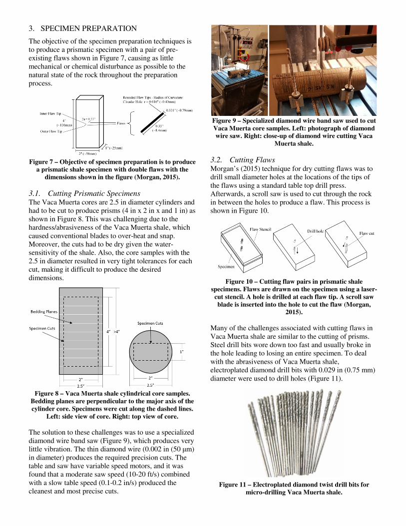
Many of the challenges associated with cutting flaws in Vaca Muerta shale are similar to the cutting of prisms. Steel drill bits wore down too fast and usually broke in the hole leading to losing an entire specimen. To deal with the abrasiveness of Vaca Muerta shale, electroplated diamond drill bits with 0.029 in (0.75 mm) diameter were used to drill holes (Figure 11).
Figure 11 – Electroplated diamond twist drill bits for
micro-drilling Vaca Muerta shale.
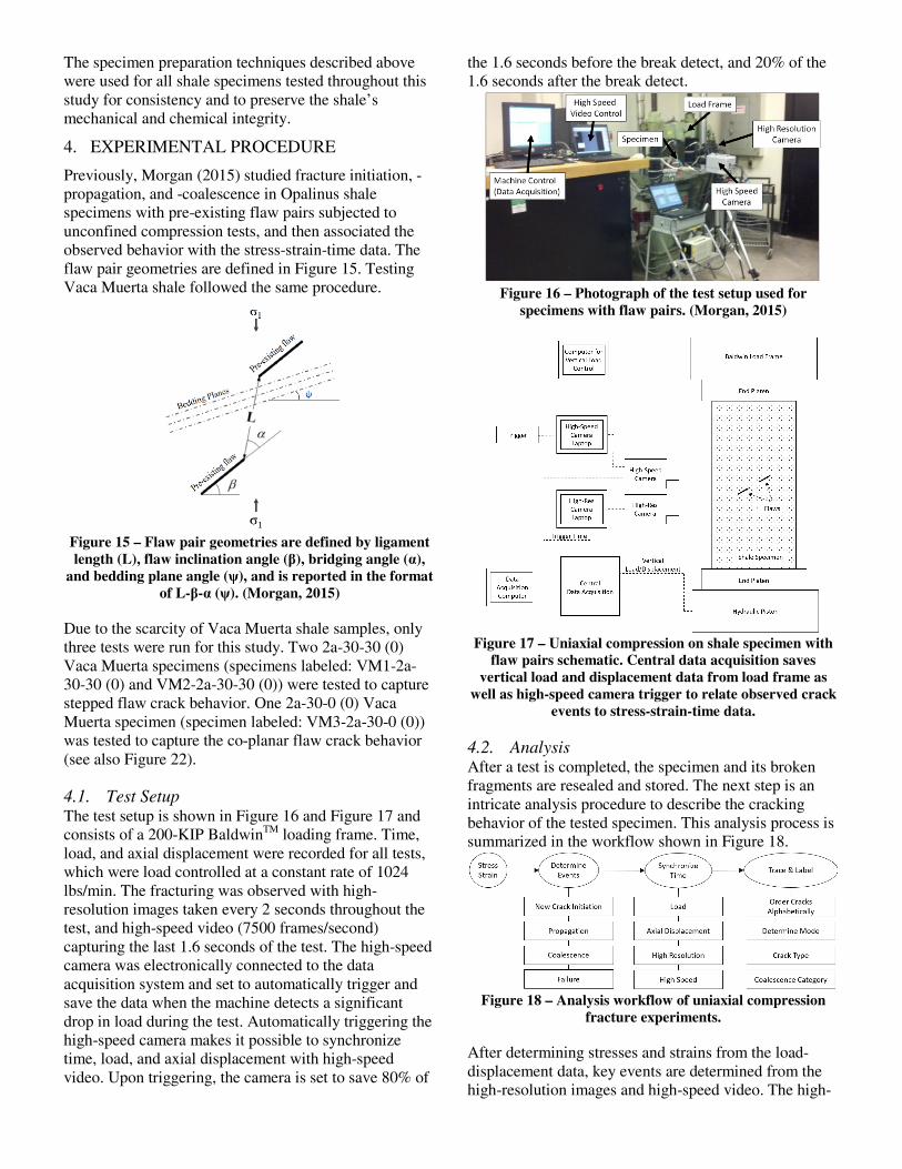
These drill bits were effective in drilling through Vaca Muerta shale, but posed some challenges. They have a length of 1.2 in, leaving a small tolerance of 0.2 in to be inserted into the chuck and drill through the 1 in thick specimen. Also, since the drill press does not allow the user to feel when the drill bit has reached the bottom of the hole; more pressure than needed could be applied and caused the bit to break. For these two reasons, a hand-feeding sensitive chuck adapter for micro-drilling was installed (Figure 12). This adapter has a keyless chuck that tightens on the drill bit as it drills, and only requires a very short length of the drill bit to be held. Also, the thumb press allows the user to feel when the drill bit contacts the bottom of the hole and prevents breaking the drill bit. Finally, the “peck drilling technique is used, where one lightly yet rapidly pushes the thumb press down and releases repeatedly, making small incremental cuts into the material. This technique keeps the flutes unclogged and cools the bit. The combination of electroplated diamond twist drill bits, the hand-feeding chuck adapter, and the peck drilling technique allows one to effectively drill clean micro-holes in shales as hard as the Vaca Muerta shale.
Figure 12 – Hand-feeding sensitive chuck adapter for
micro-drilling.
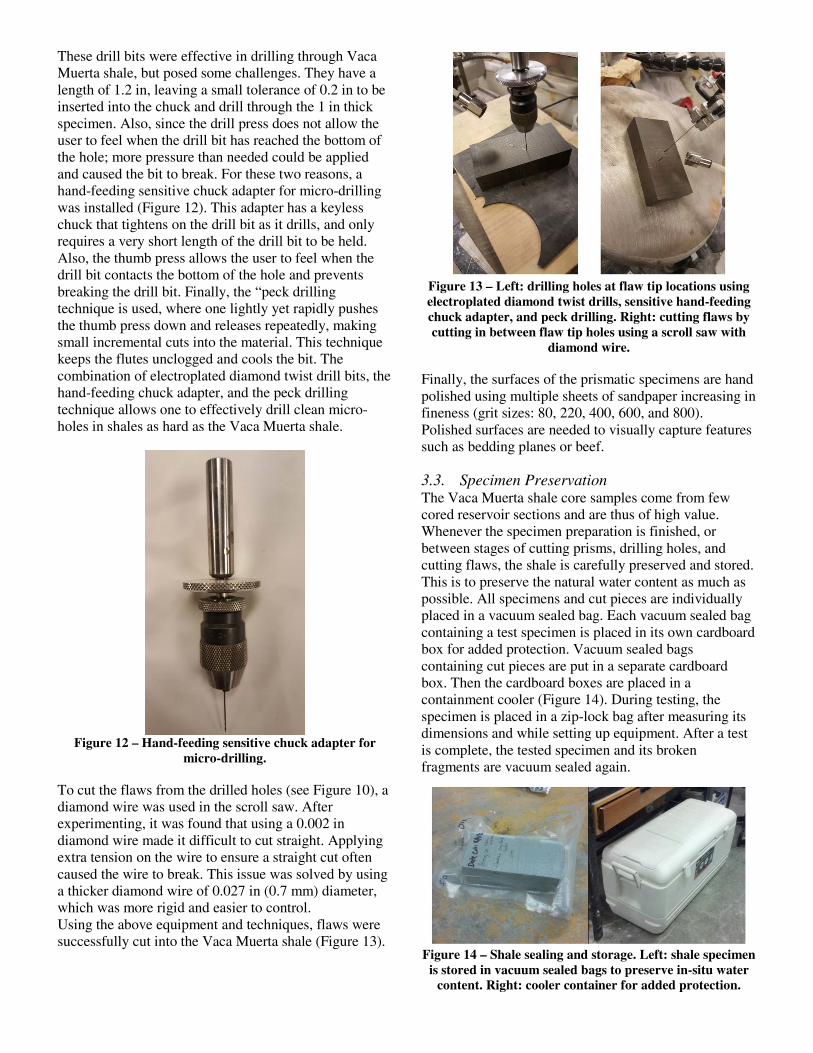
To cut the flaws from the drilled holes (see Figure 10), a diamond wire was used in the scroll saw. After experimenting, it was found that using a 0.002 in diamond wire made it difficult to cut straight. Applying extra tension on the wire to ensure a straight cut often caused the wire to break. This issue was solved by using a thicker diamond wire of 0.027 in (0.7 mm) diameter, which was more rigid and easier to control. Using the above equipment and techniques, flaws were successfully cut into the Vaca Muerta shale (Figure 13).
Figure 13 – Left: drilling holes at flaw tip locations using electroplated diamond twist drills, sensitive hand-feeding chuck adapter, and peck drilling. Right: cutting flaws by cutting in between flaw tip holes using a scroll saw with
diamond wire.
Finally, the surfaces of the prismatic specimens are hand polished using multiple sheets of sandpaper increasing in fineness (grit sizes: 80, 220, 400, 600, and 800). Polished surfaces are needed to visually capture features such as bedding planes or beef.
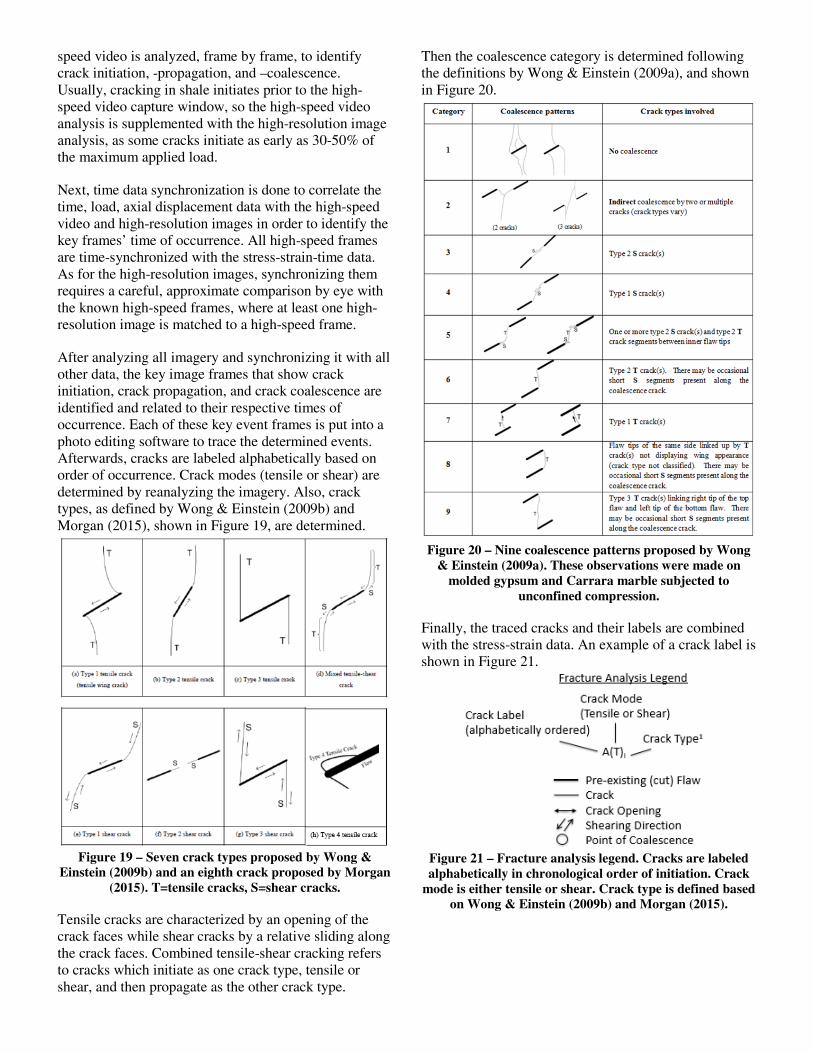
3.3. Specimen Preservation The Vaca Muerta shale core samples come from few cored reservoir sections and are thus of high value. Whenever the specimen preparation is finished, or between stages of cutting prisms, drilling holes, and cutting flaws, the shale is carefully preserved and stored. This is to preserve the natural water content as much as possible. All specimens and cut pieces are individually placed in a vacuum sealed bag. Each vacuum sealed bag containing a test specimen is placed in its own cardboard box for added protection. Vacuum sealed bags containing cut pieces are put in a separate cardboard box. Then the cardboard boxes are placed in a containment cooler (Figure 14). During testing, the specimen is placed in a zip-lock bag after measuring its dimensions and while setting up equipment. After a test is complete, the tested specimen and its broken fragments are vacuum sealed again.
Figure 14 – Shale sealing and storage. Left: shale specimen
is stored in vacuum sealed bags to preserve in-situ water content. Right: cooler container for added protection.
The specimen preparation techniques described above were used for all shale specimens tested throughout this study for consistency and to preserve the shale’s mechanical and chemical integrity.
4. EXPERIMENTAL PROCEDURE
Previously, Morgan (2015) studied fracture initiation, -propagation, and -coalescence in Opalinus shale specimens with pre-existing flaw pairs subjected to unconfined compression tests, and then associated the observed behavior with the stress-strain-time data. The flaw pair geometries are defined in Figure 15. Testing Vaca Muerta shale followed the same procedure.
Figure 15 – Flaw pair geometries are defined by ligament length (L), flaw inclination angle (β), bridging angle (α),
and bedding plane angle (ψ), and is reported in the format of L-β-α (ψ). (Morgan, 2015)
Due to the scarcity of Vaca Muerta shale samples, only three tests were run for this study. Two 2a-30-30 (0) Vaca Muerta specimens (specimens labeled: VM1-2a-30-30 (0) and VM2-2a-30-30 (0)) were tested to capture stepped flaw crack behavior. One 2a-30-0 (0) Vaca Muerta specimen (specimen labeled: VM3-2a-30-0 (0)) was tested to capture the co-planar flaw crack behavior (see also Figure 22).
4.1. Test Setup The test setup is shown in Figure 16 and Figure 17 and consists of a 200-KIP BaldwinTM loading frame. Time, load, and axial displacement were recorded for all tests, which were load controlled at a constant rate of 1024 lbs/min. The fracturing was observed with high-resolution images taken every 2 seconds throughout the test, and high-speed video (7500 frames/second) capturing the last 1.6 seconds of the test. The high-speed camera was electronically connected to the data acquisition system and set to automatically trigger and save the data when the machine detects a significant drop in load during the test. Automatically triggering the high-speed camera makes it possible to synchronize time, load, and axial displacement with high-speed video. Upon triggering, the camera is set to save 80% of
the 1.6 seconds before the break detect, and 20% of the 1.6 seconds after the break detect.
Figure 16 – Photograph of the test setup used for
specimens with flaw pairs. (Morgan, 2015)
Figure 17 – Uniaxial compression on shale specimen with
flaw pairs schematic. Central data acquisition saves vertical load and displacement data from load frame as
well as high-speed camera trigger to relate observed crack events to stress-strain-time data.
4.2. Analysis After a test is completed, the specimen and its broken fragments are resealed and stored. The next step is an intricate analysis procedure to describe the cracking behavior of the tested specimen. This analysis process is summarized in the workflow shown in Figure 18.
Figure 18 – Analysis workflow of uniaxial compression
fracture experiments.
After determining stresses and strains from the load-displacement data, key events are determined from the high-resolution images and high-speed video. The high-
speed video is analyzed, frame by frame, to identify crack initiation, -propagation, and –coalescence. Usually, cracking in shale initiates prior to the high-speed video capture window, so the high-speed video analysis is supplemented with the high-resolution image analysis, as some cracks initiate as early as 30-50% of the maximum applied load.
Next, time data synchronization is done to correlate the time, load, axial displacement data with the high-speed video and high-resolution images in order to identify the key frames’ time of occurrence. All high-speed frames are time-synchronized with the stress-strain-time data. As for the high-resolution images, synchronizing them requires a careful, approximate comparison by eye with the known high-speed frames, where at least one high-resolution image is matched to a high-speed frame.
After analyzing all imagery and synchronizing it with all other data, the key image frames that show crack initiation, crack propagation, and crack coalescence are identified and related to their respective times of occurrence. Each of these key event frames is put into a photo editing software to trace the determined events. Afterwards, cracks are labeled alphabetically based on order of occurrence. Crack modes (tensile or shear) are determined by reanalyzing the imagery. Also, crack types, as defined by Wong & Einstein (2009b) and Morgan (2015), shown in Figure 19, are determined.
Figure 19 – Seven crack types proposed by Wong &
Einstein (2009b) and an eighth crack proposed by Morgan (2015). T=tensile cracks, S=shear cracks.
Tensile cracks are characterized by an opening of the crack faces while shear cracks by a relative sliding along the crack faces. Combined tensile-shear cracking refers to cracks which initiate as one crack type, tensile or shear, and then propagate as the other crack type.
Then the coalescence category is determined following the definitions by Wong & Einstein (2009a), and shown in Figure 20.
Figure 20 – Nine coalescence patterns proposed by Wong
& Einstein (2009a). These observations were made on molded gypsum and Carrara marble subjected to
unconfined compression.
Finally, the traced cracks and their labels are combined with the stress-strain data. An example of a crack label is shown in Figure 21.
Figure 21 – Fracture analysis legend. Cracks are labeled alphabetically in chronological order of initiation. Crack
mode is either tensile or shear. Crack type is defined based on Wong & Einstein (2009b) and Morgan (2015).
5. OBSERVED FRACTURE PROCESSES IN VACA MUERTA SHALE WITH FLAWS
The tested flaw pair geometries are shown in Figure 22.
Figure 22 – Geometries of flaw pairs tested on Vaca
Muerta shale specimens. Left (a): coplanar flaw geometry with horizontal bedding planes 2a-30-0 (0). Right (b):
stepped flaw geometry with horizontal bedding planes 2a-30-30 (0).
5.1. Coplanar Flaw Geometry: 2a-30-0 (0) (Figure 22 a)
The stress-strain data are presented in Figure 23 with selected cracking events identified by symbols on the curve. The boxed numbers refer to sketched cracks that occurred at that point and documented as described in section 4.2. Analysis. In this paper, we only show the final sketches (see Figure 24 and Figure 27).
Figure 23 shows the classic initial non-linear trend indicative of seating effects as well as possible micro-cracks closing in the specimen. The specimen then quickly reaches the linear elastic regime where E50 was calculated to be 1914 MPa. Note that first crack initiation A(T)I occurred at 7.43 MPa; at about 32% of maximum stress. The specimen then started yielding around 22.8 MPa indicated by Sketch 3. This specimen reached a maximum stress of 23.2 MPa at which point it had accumulated a strain of 1.29%. The two flaws coalesced after an additional 0.14% strain occurred after 0.73 seconds from maximum stress, followed by sudden failure.
Figure 23 – Stress-strain curve for Vaca Muerta shale with coplanar flaw pair subjected to uniaxial loading. A black “x” indicates crack initiation. A red triangle indicates a
sketched frame and the boxed number indicates the sketch number. The orange circle indicates maximum stress. The
green “*” indicates coalescence stress.
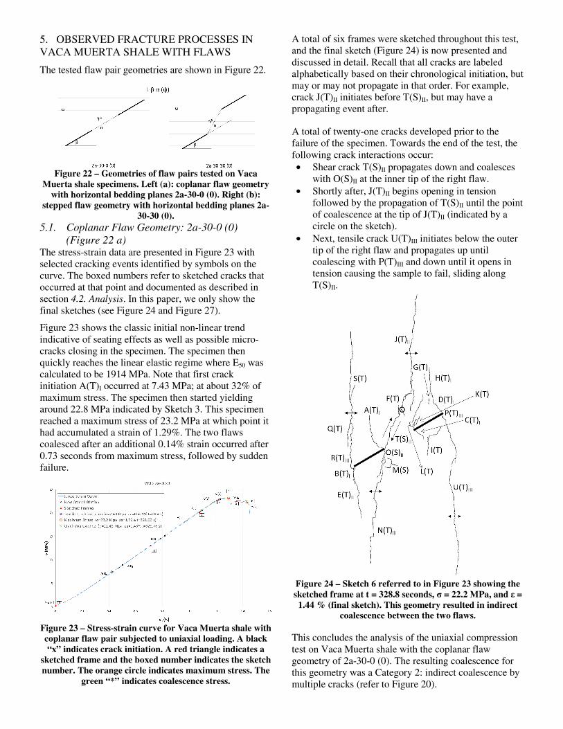
A total of six frames were sketched throughout this test, and the final sketch (Figure 24) is now presented and discussed in detail. Recall that all cracks are labeled alphabetically based on their chronological initiation, but may or may not propagate in that order. For example, crack J(T)II initiates before T(S)II, but may have a propagating event after.
A total of twenty-one cracks developed prior to the failure of the specimen. Towards the end of the test, the following crack interactions occur: • Shear crack T(S)II propagates down and coalesces
with O(S)II at the inner tip of the right flaw. • Shortly after, J(T)II begins opening in tension
followed by the propagation of T(S)II until the point of coalescence at the tip of J(T)II (indicated by a circle on the sketch).
• Next, tensile crack U(T)III initiates below the outer tip of the right flaw and propagates up until coalescing with P(T)III and down until it opens in tension causing the sample to fail, sliding along T(S)II.
Figure 24 – Sketch 6 referred to in Figure 23 showing the sketched frame at t = 328.8 seconds, σ = 22.2 MPa, and ε = 1.44 % (final sketch). This geometry resulted in indirect
coalescence between the two flaws.
This concludes the analysis of the uniaxial compression test on Vaca Muerta shale with the coplanar flaw geometry of 2a-30-0 (0). The resulting coalescence for this geometry was a Category 2: indirect coalescence by multiple cracks (refer to Figure 20).
5.2. Stepped Flaw Geometry: 2a-30-30 (0) (Figure 22 b)
The stress-strain data are presented in Figure 25 with selected events again identified by symbols on the curve.
Figure 25 shows an initial non-linear trend indicative of seating effects as well as possible micro-cracks closing in the specimen. The specimen then quickly reaches the linear elastic region where E50 was calculated to be 3051 MPa. Note that first crack initiation A(T)I occurred at 8.55 MPa; at about 32% of maximum stress. The data does not show an obvious yield point prior to fracture. This specimen reached a maximum stress of 26.2 MPa (strain of 0.976%). The two flaws coalesced and the specimen failed.
Figure 25 – Stress-strain curve for Vaca Muerta shale with
stepped flaw pair subjected to uniaxial loading. A black “x” indicates crack initiation. A red triangle indicates a
sketched frame and the boxed number indicates the sketch number. The orange circle indicates maximum stress. The
green “*” indicates coalescence stress.
A total of five frames were sketched throughout this test and now the initial (Figure 26) and final (Figure 27) sketches will be discussed in detail. All cracks are labeled alphabetically based on their chronological initiation.
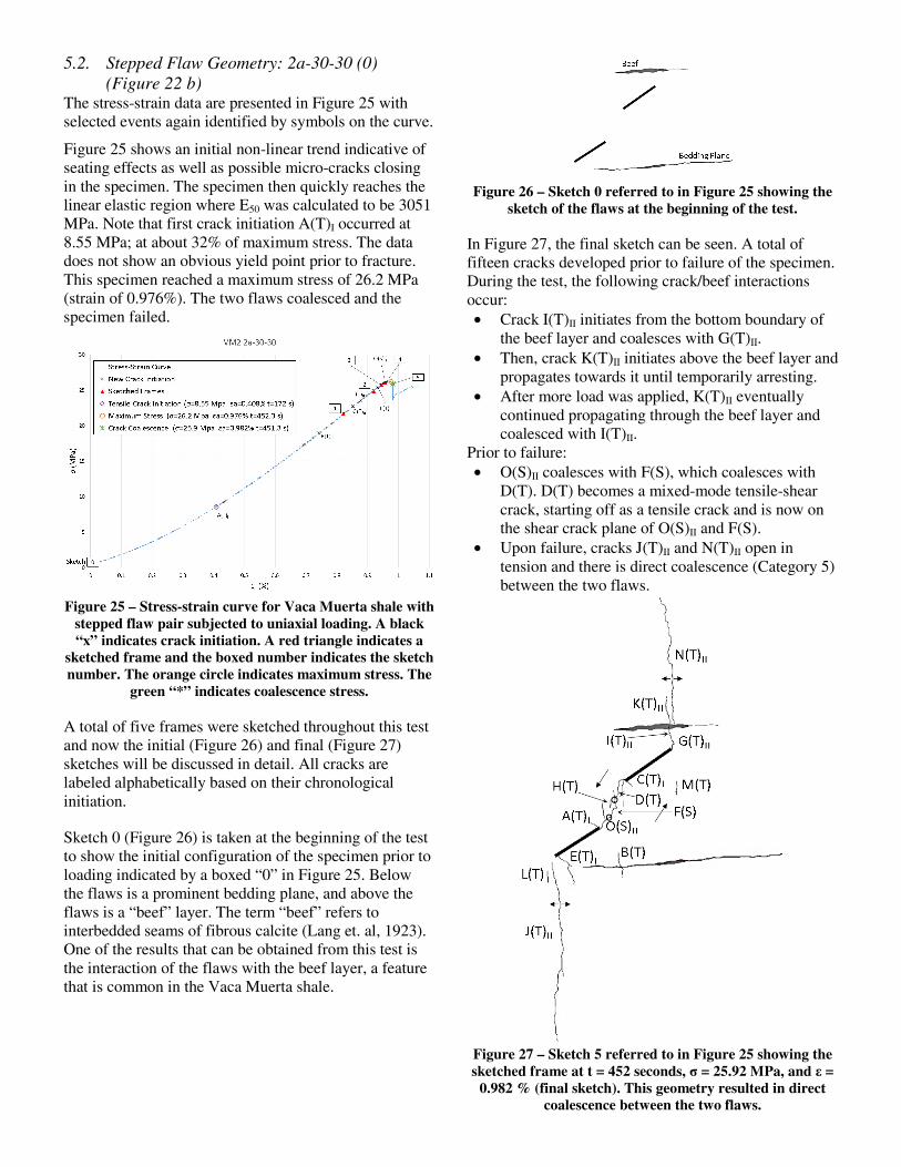
Sketch 0 (Figure 26) is taken at the beginning of the test to show the initial configuration of the specimen prior to loading indicated by a boxed “0” in Figure 25. Below the flaws is a prominent bedding plane, and above the flaws is a “beef” layer. The term “beef” refers to interbedded seams of fibrous calcite (Lang et. al, 1923). One of the results that can be obtained from this test is the interaction of the flaws with the beef layer, a feature that is common in the Vaca Muerta shale.
Figure 26 – Sketch 0 referred to in Figure 25 showing the
sketch of the flaws at the beginning of the test.
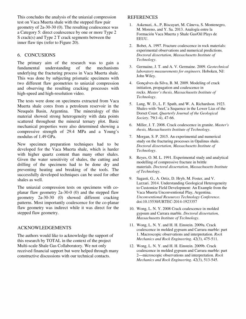
In Figure 27, the final sketch can be seen. A total of fifteen cracks developed prior to failure of the specimen. During the test, the following crack/beef interactions occur: • Crack I(T)II initiates from the bottom boundary of
the beef layer and coalesces with G(T)II. • Then, crack K(T)II initiates above the beef layer and
propagates towards it until temporarily arresting. • After more load was applied, K(T)II eventually
continued propagating through the beef layer and coalesced with I(T)II.
Prior to failure: • O(S)II coalesces with F(S), which coalesces with
D(T). D(T) becomes a mixed-mode tensile-shear crack, starting off as a tensile crack and is now on the shear crack plane of O(S)II and F(S).
• Upon failure, cracks J(T)II and N(T)II open in tension and there is direct coalescence (Category 5) between the two flaws.
Figure 27 – Sketch 5 referred to in Figure 25 showing the sketched frame at t = 452 seconds, σ = 25.92 MPa, and ε =
0.982 % (final sketch). This geometry resulted in direct coalescence between the two flaws.
This concludes the analysis of the uniaxial compression test on Vaca Muerta shale with the stepped flaw pair geometry of 2a-30-30 (0). The resulting coalescence was a Category 5: direct coalescence by one or more Type 2 S crack(s) and Type 2 T crack segments between the inner flaw tips (refer to Figure 20).
6. CONCUSIONS
The primary aim of the research was to gain a fundamental understanding of the mechanisms underlying the fracturing process in Vaca Muerta shale. This was done by subjecting prismatic specimens with two different flaw geometries to uniaxial compression and observing the resulting cracking processes with high-speed and high-resolution video.
The tests were done on specimens extracted from Vaca Muerta shale cores from a petroleum reservoir in the Neuquén Basin, Argentina. The mineralogy of this material showed strong heterogeneity with data points scattered throughout the mineral ternary plot. Basic mechanical properties were also determined showing a compressive strength of 29.4 MPa and a Young’s modulus of 1.49 GPa.
New specimen preparation techniques had to be developed for the Vaca Muerta shale, which is harder with higher quartz content than many other shales. Given the water sensitivity of shales, the cutting and drilling of the specimens had to be done dry and preventing heating and breaking of the tools. The successfully developed techniques can be used for other shales as well.
The uniaxial compression tests on specimens with co-planar flaw geometry 2a-30-0 (0) and the stepped flaw geometry 2a-30-30 (0) showed different cracking patterns. Most importantly coalescence for the co-planar flaw geometry was indirect while it was direct for the stepped flaw geometry.
ACKNOWLEDGEMENTS
The authors would like to acknowledge the support of this research by TOTAL in the context of the project Multi-scale Shale Gas Collaboratory. We not only received financial support but were helped through many constructive discussions with our technical contacts.
REFERENCES
1. Askenazi, A., P, Biscayart, M. Cáneva, S. Montenegro, M. Moreno, and Y. Sa. 2013. Analogía entre la Formación Vaca Muerta y Shale Gas/Oil Plays de EEUU.
2. Bobet, A. 1997. Fracture coalescence in rock materials: experimental observations and numerical predictions. Doctoral dissertation, Massachusetts Institute of Technology.
3. Germaine, J. T. and A. V. Germaine. 2009. Geotechnical laboratory measurements for engineers. Hoboken, NJ: John Wiley.
4. Gonçalves da Silva, B. M. 2009. Modeling of crack initiation, propagation and coalescence in rocks. Master’s thesis, Massachusetts Institute of Technology.
5. Lang, W. D., L. F. Spath, and W. A. Richardson. 1923. Shales-with-‘beef,’a Sequence in the Lower Lias of the Dorset Coast. Quarterly Journal of the Geological Society. 79(1-4), 47-66.
6. Miller, J. T. 2008. Crack coalescence in granite. Master's thesis, Massachusetts Institute of Technology.
7. Morgan, S. P. 2015. An experimental and numerical study on the fracturing processes in Opalinus shale. Doctoral dissertation, Massachusetts Institute of Technology.
8. Reyes, O. M. L. 1991. Experimental study and analytical modelling of compressive fracture in brittle materials. Doctoral dissertation, Massachusetts Institute of Technology.
9. Sagasti, G., A. Ortiz, D. Hryb, M. Foster, and V. Lazzari. 2014. Understanding Geological Heterogeneity to Customize Field Development: An Example from the Vaca Muerta Unconventional Play, Argentina. Unconventional Resources Technology Conference. doi:10.15530/URTEC-2014-1923357
10. Wong, L. N. Y. 2008 Crack coalescence in molded gypsum and Carrara marble. Doctoral dissertation, Massachusetts Institute of Technology.
11. Wong, L. N. Y. and H. H. Einstein. 2009a. Crack coalescence in molded gypsum and Carrara marble: part 1. Macroscopic observations and interpretation. Rock Mechanics and Rock Engineering. 42(3), 475-511.
12. Wong, L. N. Y. and H. H. Einstein. 2009b. Crack coalescence in molded gypsum and Carrara marble: part 2—microscopic observations and interpretation. Rock Mechanics and Rock Engineering. 42(3), 513-545.