Embed Size (px)
Citation preview

RA
FT
2/1
6/0
7
INSTRUCTION MANUAL
vacuum technologies
CT-100 Active Rough
Vacuum Gauge
D
Manual No. 699908070Revision DFebruary 2007
DR
AF
T 2
/16
/07
CT-100 Active Rough Vacuum Gauge
Alconox® is a registered trademark of Alconox, Inc.
Apiezon® L grease is a registered trademark of M&I Materials Ltd.
Copyright 2007Varian, Inc.

CT-100 Active Rough Vacuum Gauge
DR
AF
T 2
/16
/07
Warranty
Products manufactured by Seller are warranted against defects in materials and workmanship for twelve (12) months from date of shipment thereof to Customer, and Seller’s liability under valid warranty claims is limited, at the option of Seller, to repair, to replace, or refund of an equitable portion of the purchase price of the Product. Items expendable in normal use are not covered by this warranty. All warranty replacement or repair of parts shall be limited to equipment malfunctions which, in the sole opinion of Seller, are due or traceable to defects in original materials or workmanship. All obligations of Seller under this warranty shall cease in the event of abuse, accident, alteration, misuse, or neglect of the equipment. In-warranty repaired or replaced parts are warranted only for the remaining unexpired portion of the original warranty period applicable to the repaired or replaced parts. After expiration of the applicable warranty period, Customer shall be charged at the then current prices for parts, labor, and transportation.Reasonable care must be used to avoid hazards. Seller expressly disclaims responsibility for loss or damage caused by use of its Products other than in accordance with proper operating procedures.Except as stated herein, Seller makes no warranty, express or implied (either in fact or by operation of law), statutory or otherwise; and, except as stated herein, Seller shall have no liability under any war-ranty, express or implied (either in fact or by operation of law), statutory or otherwise. Statements made by any person, including representatives of Seller, which are inconsistent or in conflict with the terms of this warranty shall not be binding upon Seller unless reduced to writing and approved by an officer of Seller.
Warranty Replacement and AdjustmentAll claims under warranty must be made promptly after occurrence of circumstances giving rise thereto, and must be received within the applicable warranty period by Seller or its authorized representative. Such claims should include the Product serial number, the date of shipment, and a full description of the circumstances giving rise to the claim. Before any Products are returned for repair and/or adjust-ment, written authorization from Seller or its authorized representative for the return and instructions as to how and where these Products should be returned must be obtained. Any Product returned to Seller for examination shall be prepaid via the means of transportation indicated as acceptable by Seller. Seller reserves the right to reject any warranty claim not promptly reported and any warranty claim on any item that has been altered or has been returned by non-acceptable means of transportation. When any Product is returned for examination and inspection, or for any other reason, Customer shall be responsible for all damage resulting from improper packing or handling, and for loss in transit, notwith-standing any defect or non-conformity in the Product. In all cases, Seller has the sole responsibility for determining the cause and nature of failure, and Seller’s determination with regard thereto shall be final.If it is found that Seller’s Product has been returned without cause and is still serviceable, Customer will be notified and the Product returned at Customer’s expense; in addition, a charge for testing and exam-ination may be made on Products so returned.3/1/00
iii

CT-100 Active Rough Vacuum Gauge D
RA
FT
2/1
6/0
7
This page intentionally left blank.

CT-100 Active Rough Vacuum Gauge
DR
AF
T 2
/16
/07
Table of Contents
Warranty
Preface ...............................................................................................................................................................xiEMC Warnings ..............................................................................................................................................xi
EN 55022 Class A Warning ....................................................................................................................xiFCC ........................................................................................................................................................xi
Installation Requirements ..............................................................................................................................xiHazard and Safety Information.....................................................................................................................xii
Equipment, General..............................................................................................................................xiiiVacuum Equipment and Cleanliness.....................................................................................................xiii
Varian Services ...........................................................................................................................................xivContacting Varian .......................................................................................................................................xiv
Declaration of Conformity
Introduction ....................................................................................................................................................... 1Specifications................................................................................................................................................ 1Setup and Calibration.................................................................................................................................... 3
Factory Calibration ................................................................................................................................. 3Setup Procedures.................................................................................................................................... 3Tools and Equipment.............................................................................................................................. 4
Vacuum System Configuration ...................................................................................................................... 4Vacuum Connections.................................................................................................................................... 5
Vacuum Sealing ..................................................................................................................................... 5Electrical Connections................................................................................................................................... 6
Connecting to the Gauge........................................................................................................................ 7Calibrating the Gauge ................................................................................................................................... 9
Calibration at Intermediate Pressures .................................................................................................... 12Setting the Alarms ....................................................................................................................................... 13Cleaning ..................................................................................................................................................... 16
Exterior ................................................................................................................................................. 16Interior ................................................................................................................................................. 16
Gauge Applications..................................................................................................................................... 17Troubleshooting .......................................................................................................................................... 18
Qualified Service.................................................................................................................................. 18Changing the Vacuum Sensor ..................................................................................................................... 21Compatible Vacuum Pumps........................................................................................................................ 24Accessories and Replacement Parts............................................................................................................. 24
Request for Return Health and Safety Certification
Sales and Service Offices
v

CT-100 Active Rough Vacuum Gauge D
RA
FT
2/1
6/0
7
This page intentionally left blank.

CT-100 Active Rough Vacuum Gauge
DR
AF
T 2
/16
/07
List of Figures
Figure Caption Page1 Dimensions, inches (mm), and Important Items .................................................................... 42 9-Pin D-subminiature Connector............................................................................................ 63 Pressure Output Equivalent Circuit........................................................................................ 74 Setpoint Level Equivalent Circuit ........................................................................................... 75 Setpoint Output Driver Equivalent Circuit .............................................................................. 86 Installed CT-100..................................................................................................................... 87 Air/N2 and Argon Calibration Curves ..................................................................................... 98 Adjusting the Calibration Potentiometer............................................................................... 119 Screwdriver Adjustment of the Setpoints ............................................................................. 1310 Potentiometer Pressure Markings on the Side Panel .......................................................... 1511 Setpoint Output to the Eyesys Mini-BA................................................................................ 1712 Setpoint Output Driving a Relay Coil ................................................................................... 1713 Location of the Long Screw ................................................................................................. 2114 Location of Allen (hex) Screw .............................................................................................. 2115 Red Connector and Sensor ................................................................................................. 2216 Sensor in its Cradle.............................................................................................................. 2217 Positioning the Sensor ......................................................................................................... 23
vii

CT-100 Active Rough Vacuum Gauge D
RA
FT
2/1
6/0
7
This page intentionally left blank.

CT-100 Active Rough Vacuum Gauge
DR
AF
T 2
/16
/07
List of Tables
Table Title Page1 Specifications......................................................................................................................... 12 Vacuum Fittings ..................................................................................................................... 53 D-subminiature Connector Pinouts ........................................................................................ 64 Air/N2 and Argon Calibration Data ....................................................................................... 105 Marking Pressures ............................................................................................................... 156 Troubleshooting ................................................................................................................... 187 Compatible Vacuum Pumps ................................................................................................ 248 Accessories and Replacement Parts ................................................................................... 24
ix

CT-100 Active Rough Vacuum Gauge D
RA
FT
2/1
6/0
7
This page intentionally left blank.

CT-100 Active Rough Vacuum Gauge
DR
AF
T 2
/16
/07
Preface
EMC Warnings
EN 55022 Class A Warning
This is a Class A product. In a domestic environment this product may cause radio interference in which case the user may be required to take adequate measures.
FCC
This device complies with Part 15 of the FCC rules. Operation is subject to the following two conditions: (1) This device may not cause harmful interference, and (2) this device must accept any interference received, including interference that may cause undesirable operation.
NOTE The equipment has been tested and found to comply with the limits for a Class A digital device, pursuant to Part 15 of the FCC rules. These limits are designed to provide reasonable protection against harmful interference when the equipment is operated in a commercial environment. This equipment generated, uses, and can radiate radio frequency energy and, if not installed and used in accordance with the instruction manual, may cause harmful interference to radio communications. Operation of this equipment in a residential area is also likely to cause harmful radio communications interference in which case the user will be required to correct the interference at his own expense.
Installation RequirementsTo maintain compliance with both the FCC Part 15 rules and the European Union’s EMI directives, the user must use a shielded cable constructed of a braided shield and metal or metalized plastic backshells directly connected to the cable shield at the 15 pos D-Sub connector of the Eyesys Mini-BA. The shield must be connected to ground at the user’s equipment. Failure to install the equipment in this way may result in the unit no longer meeting the requirements for radiated emissions and susceptibility.
xi

CT-100 Active Rough Vacuum Gauge D
RA
FT
2/1
6/0
7
Hazard and Safety InformationThis manual uses the following standard safety protocols:
WARNING The warning messages are for attracting the attention of the operator to a particular procedure or practice which, if not followed correctly, could lead to serious injury.
CAUTION The caution messages are displayed before procedures, which if not followed, could cause damage to the equipment.
NOTE The notes contain important information.
Operators and service personnel must be aware of all hazards associated with this equipment. They must know how to recognize hazardous and potentially hazardous conditions, and know how to avoid them. The consequences of unskilled, improper, or careless operation of the equipment can be serious. This product must only be operated and maintained by trained personnel. Every operator or service person must read and thoroughly understand operation/maintenance manuals and any additional information provided by Varian. All warning and cautions should be read carefully and strictly observed. Consult local, state, and national agencies regarding specific requirements and regulations. Address any safety, operation, and/or maintenance questions to your nearest Varian office.
xii
CT-100 Active Rough Vacuum Gauge
DR
AF
T 2
/16
/07
Equipment, General
WARNING 1. Equipment tightness is guaranteed for normal operating conditions when the equipment leaves the factory. It is the user’s responsibility to maintain the level of tightness particularly when pumping dangerous products.
2. This product is not intrinsically safe and can initiate and sustain a fire if used with combustible gas mixtures containing hydrogen, gasoline, ethanol or similar compounds.
CAUTION The performance and operating safety of this equipment can only be guaranteed if it is operated according to normal conditions of use.
WARNING Disconnect power from the CT-100 before performing any maintenance procedure that requires physically disconnecting or opening any part of the system.
Vacuum Equipment and Cleanliness
Cleanliness is vital when servicing any vacuum equipment. The substances used for cleaning can lead to hazardous conditions or have adverse effects on the equipment.
WARNING Explosion and Fire from Acetone and Alcohol: This device may be cleaned with acetone and alcohol. When combined with air, oxygen, and other oxides, alcohol and most other solvents are very flammable and explosive. Never permit any trace of these cleaners to remain in or on the gauge. Always remove all traces of alcohol and acetone and other cleaners with clean, dry, oil-free compressed air.
CAUTION Do not use silicone oil or silicone grease.
Use powder-free butyl or polycarbonate gloves to prevent skin oils from getting on vacuum surfaces.
Do not clean any aluminum parts with Alconox®. Alconox is not compatible with aluminum and will cause damage.
NOTE Normally, it is unnecessary to use vacuum grease. However, if it must be used, avoid silicone types, and use it sparingly. Apiezon® L grease is recommended (Technologies Part Number 695400004).
xiii
CT-100 Active Rough Vacuum Gauge D
RA
FT
2/1
6/0
7
Varian ServicesPlease see our catalog, or contact us to learn of the services that are available to assist in your vacuum measurement and leak detection efforts.
Contacting VarianIn the United States, you can contact Varian Customer Service at 1-800-8VARIAN.
Internet users:
Send email to Customer Service & Technical Support at [email protected]
Visit our web site at www.varianinc.com/vacuum
Order on line at www.evarian.com
See the back cover of this manual for a listing of our sales and service offices.
xiv

Varian, Inc.121 Hartwell AvenueLexington, MA, 02421-3133 USA
declare under our sole responsibility that the product,erklären, in alleniniger Verantwortung, daß dieses Produkt,déclarons sous notre seule responsabilité que le produit,declaramos, bajo nuestra sola responsabilidad, que el producto,verklaren onder onze verantwoordelijkheid, dat het product,dichiariamo sotto nostra unica responsabilità, che il prodotto,
Declaration of ConformityKonformitätserklärungDéclaration de ConformitéDeclaración de ConformidadVerklaring de OvereenstemmingDichiarazione di Conformità
WeWirNousNosotrosWijNoi
CT-100 Active Rough Vacuum Gauge
to which this declaration relates is in conformity with the following standard(s) or other normative documents.auf das sich diese Erklärung bezieht, mit der/den flogenden Norm(en) oder Richtlinie(n) übereinstimmt.auquel se réfère cette déclaration est conforme à la (auz) norme(s) ou au(x) document(s) normatif(s).al que se refiere esta declaración es conforme a la(s) norma(s) u otro(s) documento(s) normativo(s).waamaar deze verklaring verwijst, aan de volende norm(en) of richtlijn(en) beantwoodt.a cui se rifersce questa dichiarazione è conforme alla/e sequente/I norma/o documento/I normativo/i.
Low Voltage DirectiveEN61010-1 1993 Safety requirements for electrical equipment for measurement, control,
and laboratory use, incorporating Amendments Nos. 1 and 2.EMC Emissions and Immunity
EN 61326 1997 Measurement, control and laboratory equipment, EMC requirements – Industrial use.
EMC EmissionsFCC 47 CFR part 15 Class A emissions requirements (USA).EN 55011 1998 Group 1 Class A ISM emissions requirements (EU).
Frederick C. CampbOperations ManagerVarian, Inc.Lexington, Massachu
October 2002
Declaration of Conformity
ell
setts, USA

CT-100 Active Rough Vacuum Gauge D
RA
FT
2/1
6/0
7
This page intentionally left blank.

CT-100 Active Rough Vacuum Gauge
DR
AF
T 2
/16
/07
Introduction
The CT-100 Active Rough Vacuum Gauge provides pressure measurements over a range of 1x10⁻⁴ Torr (1.33x10⁻⁴ mbar) to atmosphere. The 0.2 second response time of the CT-100 and its excellent accuracy and precision allows its use in place of Pirani gauges.
The CT-100 provides a stable analog voltage output as an indication of the test pressure; the unit can be calibrated in a selection of vacuum ranges. Two potentiometer-variable setpoints provide electrical alarms at selected pressures within the calibrated range of the device. Alarm indications are via the open collector grounding of two output transistors and by the illumination of two LEDs.
An internal power supply provides stable operating voltages from a wide range of external DC power sources.
The gauge is contained in a plastic housing mounted by a 1/8" NPT vacuum fitting. Electrical connections are on a single 9-pin D-subminiature connector.
The output pressure signal is a convenient 1.000 VDC to 9 VDC at 100 Ω internal impedance that can be used with strip chart recorders or other analog voltage data acquisition systems.
SpecificationsMeasurement, electrical and mechanical specifications for the CT-100 are given in Table 1.
Table 1 Specifications Item Description
Pressure rangesCalibration at vacuum 1x10⁻⁴ to 100 Torr, sensitive to ATM
1.33x10⁻⁴ to 133 mbar, sensitive to ATMCalibration at atmospheric pressure
20x10−2 Torr to ATM2.6x10−2 to 1000 mbar
Measurement response time 0.2 secondsOperating temperature UL recognized: From 0 °C to 40 °C; maximum relative humidity 80% for
temperatures up to 31 °C decreasing linearly to 50% relative humidity at 40 °C
Storage temperature −15 °C to 85 °CMounting orientation Vacuum port pointing down for best results above 1 Torr
(1.33 mbar)Weight with NPT fitting 560 grams (0.25 lb)
1

CT-100 Active Rough Vacuum Gauge D
RA
FT
2/1
6/0
7
The CT-100 is compatible with a wide range of Varian pumps as listed in Table 7 on page 24.
InterfaceSetpoints Two user defined pressure setpoints for process steps, alarms,
high vacuum gauge trigger, or other pressure-induced eventsSetpoint alarm output Dual, non isolated, open collector outputs 0.3 VDC @ 100 mA (ON)Setpoint voltage level 0 VDC to 12 VDC referred to analog output 100 kΩ output impedanceAdjustments
Analog voltage output Proportional to pressureNon-linear, 1 VDC to 9 VDC, nominal 100 Ω output impedance
Power supply UL recognition for 24 VDC ±10% @ 500 mA max (18 VDC to 30 VDC @ 125 mA, typical operating)
Fault <0.5 VDC or >9 VDCDisplays
Setpoint indicators Two LEDs indicating that the measured pressure is lower than the respective setpoint
Vacuum Indicator Green LED indicates <100 mTorr (0.133 mbar) vacuum is achievedConstructionMaterials exposed to vacuum Nickel plated mild steel, nickel alloyCasing Flame retardant ABS (Acrylonitrile-butadiene-styrene)Sensor element Platinel
Sensor internal volume 5.4 ml Connections
Electrical 9-pin D-subminiatureVacuum 1/8" NPT vacuum fitting
InstallationIndoor use Installation Category IIPollution category Category 2Altitude 2000 m
Table 1 Specifications (Continued)Item Description
2

CT-100 Active Rough Vacuum Gauge
DR
AF
T 2
/16
/07
Setup and Calibration
Factory Calibration
The CT-100 is calibrated at the factory at high vacuum of 10-5 Torr (1.33x10⁻⁵ mbar). You will achieve the highest measurement accuracy by recalibrating the gauge after installation of the vacuum system using the procedure in “Calibrating the Gauge” on page 9.
Setup Procedures
There are four procedures involved in applying the CT-100 to a vacuum system. This ease of use coupled with the simplicity of fault repair makes the CT-100 very desirable in situations where many gauges are employed and in harsh environments that can lead to stress on the gauge and subsequent expectation of short life.
The setup procedures are:
1. Mount the gauge with its NPT fitting facing downward. A range of fitting adaptors is available from Varian as listed in Table 2 on page 5.
CAUTION Do not tighten the fitting by twisting the plastic case as this will result in damage to the gauge. Use the wrench specified in “Tools and Equipment” on page 4 below.
2. Plug the single electrical cable into the D-connector and appropriately connect the free-end wires according to information in Table 3 on page 6.
3. Perform a one-point calibration of the non-linear sensor as described in “Calibrating the Gauge” on page 9.
Calibration must be done at vacuum below 1x10⁻⁴ Torr (1.33x10⁻⁴ mbar) or at atmosphere, depending on the expected range of the gauge use. Calibration at intermediate pressures may also be performed with the use of a calibrated pressure reference.
NOTE Record the pressure at which you performed the calibration.
4. Adjust the two setpoint potentiometers to the desired trigger levels as described in “Setting the Alarms” on page 13. If you do not want either alarm to go off, turn the potentiometers fully clockwise to maximum vacuum, a level that may not be expected for this system.
3
CT-100 Active Rough Vacuum Gauge D
RA
FT
2/1
6/0
7
Tools and Equipment
Have the following items available for setup and calibration.
7/16" wrench for the 1/8" NPT fitting
Digital voltmeter
24 VDC power supply, 125 mA capacity
Vacuum pump able to reach 1x10⁻⁵ Torr, (1.33x10⁻³ mbar) with its necessary fittings
Plumber’s sealing tape or other suitable thread sealant
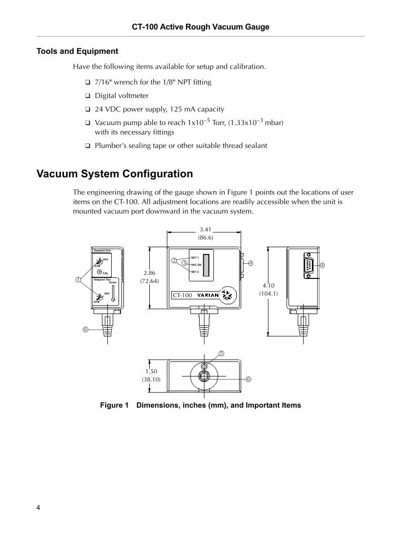
Vacuum System ConfigurationThe engineering drawing of the gauge shown in Figure 1 points out the locations of user items on the CT-100. All adjustment locations are readily accessible when the unit is mounted vacuum port downward in the vacuum system.
Figure 1 Dimensions, inches (mm), and Important Items
1
5
6
6
43 4
Setpoint One
VAC
ATM
CAL
Down
ATM
Setpoint Two
VAC
2.86(72.64)
3.41(86.6)
CT-100
4.10(104.1)
1.50(38.10)
SET 1
VAC OK
SET 2
2
4

CT-100 Active Rough Vacuum Gauge
DR
AF
T 2
/16
/07
Important items shown in the figure are:
➀ Potentiometers — Setpoints 1 and 2
➁ Setpoint alarm LEDs
These LEDs are OFF until the vacuum reaches the setpoint level. Thereafter, they remain RED as long as the pressure stays below the setpoint.
➂ VACuum OK indicator
This LED is OFF at atmospheric pressure and turns GREEN when the vacuum is below 100 milliTorr (0.133 mbar).
➃ 9-pin D-subminiature connector for interface cable to the electrical system.
➄ Allen screw access for fixing the sensor orientation after replacement.
➅ 1/8" NPT vacuum fitting
Vacuum ConnectionsVacuum fitting may be purchased from Varian to mate your system with the 1/8" NPT fitting integral to the CT-100. The available stainless steel and aluminum fittings are listed in Table 2. Be sure the appropriate fitting for the vacuum system to be measured is installed on your CT-100.
nan
NOTE Mount the gauge with the vacuum port facing downward for optimum measurement accuracy.
Vacuum Sealing
The CT-100 must be securely connected to the vacuum system to be tested. Seal all threaded joints using plumber’s tape or an appropriate sealant. Tighten the thread securely.
Table 2 Vacuum FittingsFitting Size
Varian Part Number
304 Stainless Steel
KF16 KAFP160125SKF25 KAFP250125S
Aluminum
KF16 KAFP160125AKF25 KAFP250125A
5

CT-100 Active Rough Vacuum Gauge D
RA
FT
2/1
6/0
7
Electrical ConnectionsAll signals and voltages are handled through a 9-pin D-subminiature connector mounted on the side of the CT-100 as shown in Figure 1 on page 4.
The electrical pinouts for this connector are given in Table 3. The connector pin layout is shown in Figure 2.
Figure 2 9-Pin D-subminiature Connector
Table 3 D-subminiature Connector PinoutsPin No. Description
1. Relay #2 N.O.2. Relay #1 N.O.3. Power Input (+24 VDC)4. Power Ground5. Analog Output6. Relay Common7. Setpoint #2 Output8. Signal Ground9. Setpoint #1 OutputShell Chassis Ground in the gauge. Connect
to the Power Supply at the Power Supply
5 1
9 6
6

CT-100 Active Rough Vacuum Gauge
DR
AF
T 2
/16
/07
Connecting to the Gauge
The CT-100 generates five signal levels that are externally measured or sensed. These signals, with their pin location on the D-subminiature connector, are given in Table 3.
The voltage on pin 5 represents the pressure in the test object. The equivalent circuit for this output is shown in Figure 3.
Figure 3 Pressure Output Equivalent Circuit
The voltages on pins 7 and 9 represent the setpoint alarm pressures. These voltages are taken from the wipers of the screwdriver-adjust potentiometers respectively labelled Setpoint 2 and Setpoint 1 in Figure 1 on page 4. The circuit for these outputs is shown in Figure 4. The sensing circuit loaded on this output should have an impedance of at least 10 MegΩ.
Figure 4 Setpoint Level Equivalent Circuit
5
8
100 Ω
8
7, 9
100 Ω
7

CT-100 Active Rough Vacuum Gauge D
RA
FT
2/1
6/0
7
The voltage on pins 1 and 2 are the switched collectors indicative of a tripped setpoint alarm. The equivalent circuit for these outputs is shown in Figure 5. The collector is clamped to ground when the setpoint level is reached. This circuit can sink up to 100 mA from a supply of up to 30 VDC.
CAUTION Since the usual driven element is a relay coil, a snubber diode is required for protection from inductive flyback as is shown below and in Figure 12 on page 17.
Figure 5 Setpoint Output Driver Equivalent Circuit
The CT-100 appears as shown in Figure 6 when mounted in a vacuum system.
.
Figure 6 Installed CT-100
NOTE Mount the gauge with the vacuum port facing downward for optimum measurement accuracy.
6
36 V
1, 20.3 V
8

CT-100 Active Rough Vacuum Gauge
DR
AF
T 2
/16
/07
Calibrating the GaugePerform a recalibration every few months or more often as needed (see Table 6 on page 18) based on the temperature and the process chemistry in which the gauge is used. Your Varian Customer Support Center can provide advice on establishing a routine calibration schedule for your applications. See the rear cover of this manual for a list of Center locations.
The CT-100 pressure vs. voltage calibration curves for air and argon are given in Figure 7. The data on which to base a calibration are given in Table 4 on page 10. The calibration procedure for any gas without a reference gauge is based on establishing a datum at either:
The ultimate vacuum for the CT-100 at 1x10⁻⁵ Torr (1.33x10⁻⁵ mbar) where the gauge output voltage is set to 1.000 VDC for any gas, or
At atmospheric pressure of 760 Torr (1000 mbar) where the gauge voltage is set to:
8.255 VDC in air/N2, or
6.783 VDC in argon.
Figure 7 Air/N2 and Argon Calibration Curves
Out
put (
Volts
)
10-4 10-3 10-2 10-1 1 10 100 1000 Torr1.33x10-4 1.33x10⁻³ 1.33x10⁻² 1.33x10⁻¹ 1.33 13.3 133 1330 mbar1.33x10-2 1.33x10⁻¹ 1.33 13.3 1.33x10² 1.33x10³ 1.33x10⁴ 1.33x10⁵ Pa
Pressure
9

CT-100 Active Rough Vacuum Gauge D
RA
FT
2/1
6/0
7
Table 4 Air/N2 and Argon Calibration Data
To calibrate the CT-100:
1. Connect the gauge to the vacuum system to be measured.
If you want to establish the datum at atmospheric pressure, the system does not have to be pumped down.
2. Connect the cable to a power supply.
3. Connect a voltmeter to gauge ground pin # 4 and to gauge output pin # 5 on the cable from the D-connector.
Pressure (Torr)
Pressure (mbar)
Pressure (Pa)
Vout
(Air/N2)Vout
(Argon)
1.00E-04 1.33E-04 1.33E-02 1.002 1.0022.00E-04 2.66E-04 2.66E-02 1.004 1.0035.00E-04 6.65E-04 6.65E-02 1.007 1.0051.00E-03 1.33E-03 1.33E-01 1.013 1.0082.00E-03 2.66E-03 2.66E-01 1.025 1.0155.00E-03 6.65E-03 6.65E-01 1.055 1.0361.00E-02 1.33E-02 1.33E+00 1.111 1.0692.00E-02 2.66E-02 2.66E+00 1.216 1.1365.00E-02 6.65E-02 6.65E+00 1.501 1.3301.00E-01 1.33E-01 1.33E+01 1.940 1.5622.00E-01 2.66E-01 2.66E+01 2.540 2.0855.00E-01 6.65E-01 6.65E+01 3.678 2.9771.00E+00 1.33E+00 1.33E+02 4.737 3.7872.00E+00 2.66E+00 2.66E+02 5.703 4.3125.00E+00 6.65E+00 6.65E+02 6.547 5.2881.00E+01 1.33E+01 1.33E+03 6.999 5.5982.00E+01 2.66E+01 2.66E+03 7.241 5.8925.00E+01 6.65E+01 6.65E+03 7.405 6.0171.00E+02 1.33E+02 1.33E+04 7.463 6.0652.00E+02 2.66E+02 2.66E+04 7.548 6.0975.00E+02 6.65E+02 6.65E+04 7.762 6.3477.60E+02 1.01E+03 1.01E+05 8.255 6.783
10

CT-100 Active Rough Vacuum Gauge
DR
AF
T 2
/16
/07
4. Plug the cable into the gauge and turn the power supply ON.
5. Allow the gauge to warm up for 1/2-hour.
To calibrate at atmosphere, go to step 6.
To calibrate at vacuum, go to step 7.
6. Adjust the CAL screwdriver potentiometer as shown in Figure 8 until the voltmeter reads 8.255 VDC.
If calibrating in an argon atmosphere, adjust the output to 6.783 VDC.
The gauge is now calibrated with maximum accuracy obtained near atmospheric levels.
Figure 8 Adjusting the Calibration Potentiometer
To calibrate the gauge for optimum accuracy at high vacuum levels:
7. Connect the gauge to a pump and precision gauge able to achieve and measure 1x10⁻⁵ Torr (1.33x10⁻⁵ mbar) or lower.
8. Adjust the CAL screwdriver potentiometer as shown in Figure 8 until the voltmeter reads 1.000 volts.
Note in Table 4 that the output voltage rises by 2 millivolts at the lowest accurately measurable level for the CT-100, 1x 10⁻⁴ Torr (1.33x10⁻⁴ mbar).
The gauge is now calibrated for measurements from 10−4 to 100 Torr (1.33x10⁻⁴ to 133 mbar).
Calibration
11

CT-100 Active Rough Vacuum Gauge D
RA
FT
2/1
6/0
7
Calibration at Intermediate Pressures
The CT-100 can be calibrated at intermediate pressures to attain the best accuracy near that level, or to compensate for use at high altitude.
To calibrate the gauge at intermediate pressures:
1. Determine the pressure at which you want to calibrate the gauge.
If the gauge is being operated at high altitude, determine the local air pressure.
2. Refer to the chart in Figure 7 on page 9 or to Table 4 on page 10 and determine the output voltage corresponding to that pressure.
A linear interpolation between points in the table will provide sufficient accuracy.For example, at a calibration pressure of 20 milliTorr (0.266 mbar), the output voltage should be adjusted to 1.216 VDC as shown in Table 4.
3. Use a calibrated reference gauge to verify that the pressure in the system is at the desired value.
4. Adjust the CAL potentiometer until the output voltage reads the value just determined.
12
CT-100 Active Rough Vacuum Gauge
DR
AF
T 2
/16
/07
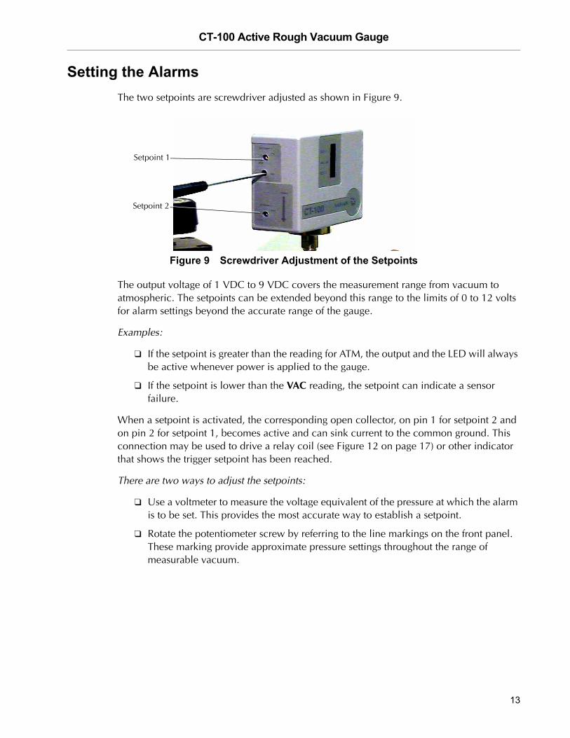
Setting the AlarmsThe two setpoints are screwdriver adjusted as shown in Figure 9.
Figure 9 Screwdriver Adjustment of the Setpoints
The output voltage of 1 VDC to 9 VDC covers the measurement range from vacuum to atmospheric. The setpoints can be extended beyond this range to the limits of 0 to 12 volts for alarm settings beyond the accurate range of the gauge.
Examples:
If the setpoint is greater than the reading for ATM, the output and the LED will always be active whenever power is applied to the gauge.
If the setpoint is lower than the VAC reading, the setpoint can indicate a sensor failure.
When a setpoint is activated, the corresponding open collector, on pin 1 for setpoint 2 and on pin 2 for setpoint 1, becomes active and can sink current to the common ground. This connection may be used to drive a relay coil (see Figure 12 on page 17) or other indicator that shows the trigger setpoint has been reached.
There are two ways to adjust the setpoints:
Use a voltmeter to measure the voltage equivalent of the pressure at which the alarm is to be set. This provides the most accurate way to establish a setpoint.
Rotate the potentiometer screw by referring to the line markings on the front panel. These marking provide approximate pressure settings throughout the range of measurable vacuum.
Setpoint 1
Setpoint 2
13

CT-100 Active Rough Vacuum Gauge D
RA
FT
2/1
6/0
7
Voltmeter adjustment of a setpoint:
1. Connect power to a CT-100 gauge that has been calibrated. The voltage to be measured is from 0 up to 12 VDC. If necessary, set the voltmeter scale to measure this range.
2. Attach the voltmeter ground to pin 8 on the D-connector cable.
3. Attach the voltmeter probe to pin 9 to measure setpoint #1 and to pin 7 for setpoint #2 as determined from Table 3 on page 6. At this point you are reading the voltage on the wiper of the selected potentiometer.
4. Refer to the Table 4 on page 10 or to Figure 7 on page 9 for the gas you wish to measure.
This data is given in Torr, mbar, and Pascals on the pressure X-axis.
5. Locate the pressure for the setpoint on the X-axis of the chart and read off the voltage from the Y-axis, or find a specific pressure in the table and its associated voltage. Use a linear interpolation between the nearest data points for intermediate values.
6. Adjust the screwdriver potentiometer for the appropriate setpoint until the voltmeter reads the value indicated on the curve or the table.
You can calibrate to three decimal places, ±1 millivolt.
NOTE If you are measuring a different gas, the setpoints must be readjusted.
14

CT-100 Active Rough Vacuum Gauge
DR
AF
T 2
/16
/07
Setpoint Adjustment from Panel Markings:
Each setpoint can be brought to an approximate pressure level by rotating the screwdriver adjustment according to the markings on the side panel surrounding the potentiometer. These markings are placed approximately at each decade of vacuum (refer to Figure 10 and Table 5).
Figure 10 Potentiometer Pressure Markings on the Side Panel
Table 5 Marking PressuresMarking Clockwise Torr mbar
ATM 760 10001 100 1332 10 13.33 1 1.334 100 mT 1.33x10⁻¹
5 10 mT 1.33x10⁻²
VAC 1 mT 1.33x10⁻³
15

CT-100 Active Rough Vacuum Gauge D
RA
FT
2/1
6/0
7
Cleaning
Exterior
The exterior of the CT-100 may be kept clean using a cloth slightly dampened with water.
Interior
Remove all power from the CT-100 before opening the cover to clean its internal parts. To remove the cover, follow the procedure given in “Changing the Vacuum Sensor” on page 21. The only internal part that may require cleaning is the vacuum port and the sensor mounted inside the port. Use alcohol or acetone for cleaning.
WARNING Explosion and Fire from Acetone and Alcohol: This device may be cleaned with acetone and alcohol. When combined with air, oxygen, and other oxides, alcohol and most other solvents are very flammable and explosive. Never permit any trace of these cleaners to remain in or on the gauge. Always remove all traces of alcohol and acetone and other cleaners with clean, dry, oil-free compressed air.
16
CT-100 Active Rough Vacuum Gauge
DR
AF
T 2
/16
/07
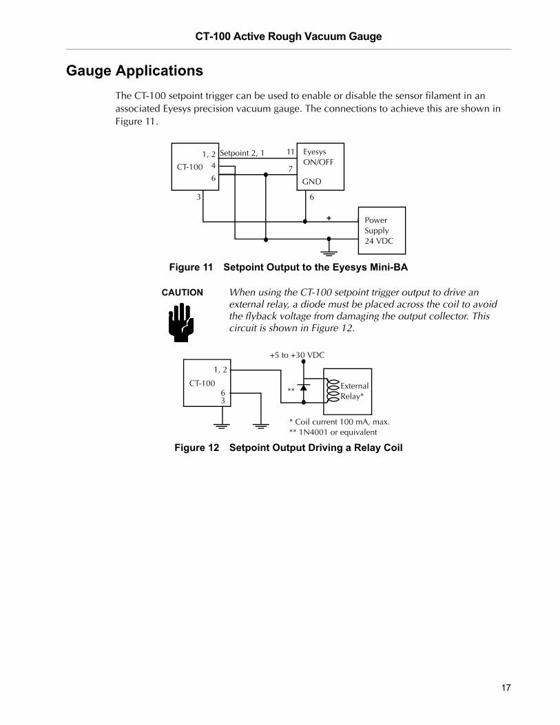
Gauge ApplicationsThe CT-100 setpoint trigger can be used to enable or disable the sensor filament in an associated Eyesys precision vacuum gauge. The connections to achieve this are shown in Figure 11.
Figure 11 Setpoint Output to the Eyesys Mini-BA
CAUTION When using the CT-100 setpoint trigger output to drive an external relay, a diode must be placed across the coil to avoid the flyback voltage from damaging the output collector. This circuit is shown in Figure 12.
Figure 12 Setpoint Output Driving a Relay Coil
CT-100
1, 24
6
3
11
7
GND
6
Setpoint 2, 1 Eyesys ON/OFF
Power Supply 24 VDC
1, 2
36
ExternalRelay*
+5 to +30 VDC
* Coil current 100 mA, max.
CT-100**
** 1N4001 or equivalent
17
CT-100 Active Rough Vacuum Gauge D
RA
FT
2/1
6/0
7
Troubleshooting
Qualified Service
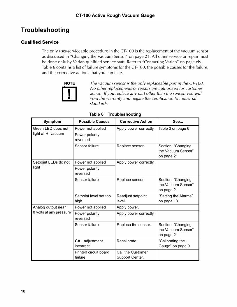
The only user-serviceable procedure in the CT-100 is the replacement of the vacuum sensor as discussed in “Changing the Vacuum Sensor” on page 21. All other service or repair must be done only by Varian qualified service staff. Refer to “Contacting Varian” on page xiv. Table 6 contains a list of failure symptoms for the CT-100, the possible causes for the failure, and the corrective actions that you can take.
NOTE The vacuum sensor is the only replaceable part in the CT-100. No other replacements or repairs are authorized for customer action. If you replace any part other than the sensor, you will void the warranty and negate the certification to industrial standards.
Table 6 Troubleshooting Symptom Possible Causes Corrective Action See...
Green LED does not light at HI vacuum
Power not applied Apply power correctly. Table 3 on page 6Power polarity reversedSensor failure Replace sensor. Section “Changing
the Vacuum Sensor” on page 21
Setpoint LEDs do not light
Power not applied Apply power correctly.Power polarity reversedSensor failure Replace sensor. Section “Changing
the Vacuum Sensor” on page 21
Setpoint level set too high
Readjust setpoint level.
“Setting the Alarms” on page 13
Analog output near 0 volts at any pressure
Power not applied Apply power.Power polarity reversed
Apply power correctly.
Sensor failure Replace the sensor. Section “Changing the Vacuum Sensor” on page 21
CAL adjustment incorrect
Recalibrate. “Calibrating the Gauge” on page 9
Printed circuit board failure
Call the Customer Support Center.
18

CT-100 Active Rough Vacuum Gauge
DR
AF
T 2
/16
/07
Analog output above 9 volts at any pressure
Supply voltage greater than 30 VDC
Reduce the supply voltage.
Sensor contaminated Clean the sensor. “Cleaning” on page 16Sensor failure Replace the sensor. Section “Changing
the Vacuum Sensor” on page 21
Draws excessive power. Supply current > 125 mA
Printed circuit board failure
Call the Customer Support Center.
Does not track calibration curve
CAL adjustment incorrect
Recalibrate. “Calibrating the Gauge” on page 9
Gas other than air or argon
Calibrate with the actual gas used.
Contaminated sensor Clean or replace the sensor.
Section “Changing the Vacuum Sensor” on page 21
Leak at pipe thread fitting
Reattach the CT-100 with new thread sealant using the proper torque.
“Vacuum Sealing” on page 5
Analog output unstable
Power supply voltage too high
Lower the voltage to under 30 VDC.
Section “Changing the Vacuum Sensor” on page 21
Sensor failure Replace the sensor. Section “Changing the Vacuum Sensor” on page 21
Cable shield and power return tied together at gauge
Tie the cable shield and power return together at the power supply, only.
Use of unshielded cable
Use a shielded cable grounded at the power supply.
RFI or EMI are above the limits of EN61326
Reduce the RFI and EMI to below levels of EN61326 or add additional shielding.
Pressure in chamber fluctuates
No action required. Gauge responds to pressure changes of 0.2 seconds.
Table 6 Troubleshooting (Continued)Symptom Possible Causes Corrective Action See...
19

CT-100 Active Rough Vacuum Gauge D
RA
FT
2/1
6/0
7
Unable to calibrate Incorrect pressure level
Replace the sensor. Section “Changing the Vacuum Sensor” on page 21Sensor failure
Printed circuit board failure
Call the Customer Support Center.
Setpoint potentiometer markings not accurate
Markings are approximate
Use setpoint level outputs to obtain an accurate setting.
“Setting the Alarms” on page 13
Setpoint outputs stay at 0 volts
No pull-up resistor Connect a pull-up resistor.
Figure 5 on page 8
Printed circuit board failure
Call the Customer Support Center.
Table 6 Troubleshooting (Continued)Symptom Possible Causes Corrective Action See...
20

CT-100 Active Rough Vacuum Gauge
DR
AF
T 2
/16
/07
Changing the Vacuum SensorThe thermal pressure vacuum sensor is mounted inside the plastic housing and is accessible for changing by opening the housing. Perform this work at an ESD controlled workstation.
Tools required:
Phillips head screwdriver, small
Allen (hex) wrench, 1/8"
To replace the sensor:
1. Disconnect the D-connector plug from the CT-100.
2. Remove the CT-100 from the vacuum system.
3. Remove three screws holding the cover to the gauge body and lift the cover off.
The screw at the position shown in Figure 13 is longer than the other two screws and must be returned to the same place when reassembling the cover.
Figure 13 Location of the Long Screw
4. Locate the Allen (hex) screw at the top, outer end of the sensor body.
Use a 1/8" hex wrench and remove the screw as shown in Figure 14.
Figure 14 Location of Allen (hex) Screw
21

CT-100 Active Rough Vacuum Gauge D
RA
FT
2/1
6/0
7
5. Locate and unplug the red plastic connector that attaches the cable from the sensor to the circuit board, as shown in Figure 15.
Figure 15 Red Connector and Sensor
6. Lift the sensor and its attached cable out of the gray plastic cradle.
7. Put the new sensor into the cradle. Be sure to locate the tube and wires as shown in Figure 16.
Figure 16 Sensor in its Cradle
Red PlasticSensor
Circuit Board
Connector
22

CT-100 Active Rough Vacuum Gauge
DR
AF
T 2
/16
/07
8. Rotate the sensor so the Allen screw anchor hole is at the top of the assembly and is visible through the hole in the cover as shown in Figure 17.
Figure 17 Positioning the Sensor
9. Insert and finger tighten the Allen screw.
10. Reattach the red connector. The connector is polarized to be inserted in only a specific orientation and with full alignment of plug and socket.
CAUTION Sensor failure may take place if the connector and plug are not aligned and if any pins are not firmly engaged.
11. Replace the gauge cover and fully tighten the Allen screw.
12. Locate the longer of the cover screws and insert it in the lower left position as shown in Figure 15 on page 22 with the vacuum port facing upward.
13. Replace the remaining two screws and replace the gauge in the vacuum system.
14. Calibrate the gauge using the procedure in “Calibrating the Gauge” on page 9.
23

CT-100 Active Rough Vacuum Gauge D
RA
FT
2/1
6/0
7
Compatible Vacuum Pumps
Accessories and Replacement Parts
Table 7 Compatible Vacuum Pumps Product
Vacuum PumpsSH-100 Dry Scroll TriScroll Series - TS-300, 320, 600, 620Rotary Vane Turbo Molecular IonDiffusion
Vacuum GaugesHigh Vacuum Gauge - Mini BA (Digital)High Vacuum Gauge - Mini IMG (Analog)
Table 8 Accessories and Replacement Parts Item Part Number
Interface Cable with 9 -pin, D-subminiature male connector R0907xyzxyz = length in feet
Power Supply/Breakout Box [24 VDC power and signal test points] 670077101Vacuum Sensor 1/8" NPT L7426601RJ45 Adapter for Edwards ATC and APG L7439301Mating DSUB Connector Kit L7440301
Vacuum Fittings: 304 Stainless SteelKF16 KAFP160125SKF25 KAFP250125S
Vacuum Fittings: AluminumKF16 KAFP160125AKF25 KAFP250125A
24
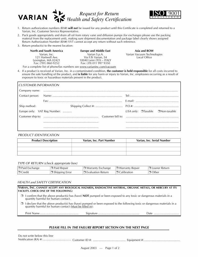
Request for Return Health and Safety Certification
1. Return authorization numbers (RA#) will not be issued for any product until this Certificate is completed and returned to a Varian, Inc. Customer Service Representative.
2. Pack goods appropriately and drain all oil from rotary vane and diffusion pumps (for exchanges please use the packing material from the replacement unit), making sure shipment documentation and package label clearly shows assigned Return Authorization Number (RA#) VVT cannot accept any return without such reference.
3. Return product(s) to the nearest location:
4. If a product is received at Varian, Inc. in a contaminated condition, the customer is held responsible for all costs incurred to ensure the safe handling of the product, and is liable for any harm or injury to Varian, Inc. employees occurring as a result of exposure to toxic or hazardous materials present in the product.
PLEASE FILL IN THE FAILURE REPORT SECTION ON THE NEXT PAGE
North and South America Europe and Middle East Asia and ROWVarian, Inc.
121 Hartwell Ave.Lexington, MA 02421Fax: (781) 860-9252
Varian S.p.A.Via F.lli Varian, 54
10040 Leini (TO) – ITALYFax: (39) 011 997 9350
Varian Vacuum TechnologiesLocal Office
For a complete list of phone/fax numbers see www.varianinc.com/vacuum
Do not write below this lineNotification (RA) #: ................................... Customer ID #: ........................................ Equipment #: ............................................
CUSTOMER INFORMATION
Company name: ......................................................................................................................................................................
Contact person: Name: ...................................................................................... Tel:............................................................
Fax: .......................................................................................... E-mail: .....................................................
Ship method: Shipping Collect #: .................................. P.O.#: .......................................................
Europe only: VAT Reg Number: ........... USA only: Taxable Non-taxable
Customer ship to: .................................................................... Customer bill to: .................................................................
.................................................................... .................................................................
.................................................................... .................................................................
PRODUCT IDENTIFICATION
Product Description Varian, Inc. Part Number Varian, Inc. Serial Number
TYPE OF RETURN (check appropriate box) Paid Exchange Paid Repair Warranty Exchange Warranty Repair Loaner Return Credit Shipping Error Evaluation Return Calibration Other
HEALTH and SAFETY CERTIFICATION
VARIAN, INC. CANNOT ACCEPT ANY BIOLOGICAL HAZARDS, RADIOACTIVE MATERIAL, ORGANIC METALS, OR MERCURY AT ITS FACILITY. CHECK ONE OF THE FOLLOWING:
I confirm that the above product(s) has (have) NOT pumped or been exposed to any toxic or dangerous materials in aquantity harmful for human contact.
I declare that the above product(s) has (have) pumped or been exposed to the following toxic or dangerous materials in a quantity harmful for human contact (Must be filled in):
Print Name................................................ Signature ................................................... Date ...............................
August 2003 — Page 1 of 2
ISOR E G I S T E R E D
9001
Request for Return Health and Safety Certification

Request for ReturnHealth and Safety Certification
FAILURE REPORT (Please describe in detail the nature of the malfunction to assist us in performing failure analysis):
TURBO PUMPS AND TURBOCONTROLLERS
ION PUMPS/CONTROLLERS VALVES/COMPONENTS
LEAK DETECTORS INSTRUMENTS
ALL OTHER VARIAN, INC. DIFFUSION PUMPS
Claimed Defect Position Parameters Does not start Noise Vertical Power: Rotational Speed: Does not spin freely Vibrations Horizontal Current: Inlet Pressure: Does not reach full speed Leak Upside-down Temp 1: Foreline Pressure: Mechanical Contact Overtemperature Other
................................Temp 2: Purge flow:
Cooling defective Clogging Operation Time:Describe Failure:
Turbocontroller Error Message:
Bad feedthrough Poor vacuum Main seal leak Bellows leak Vacuum leak High voltage problem Solenoid failure Damaged flange Error code on display Other .............................. Damaged sealing area Other ...............................Describe failure: Describe failure:
Customer application: Customer application:
Cannot calibrate No zero/high background Gauge tube not working Display problem Vacuum system unstable Cannot reach test mode Communication failure Degas not working Failed to start Other ............................... Error code on display Other ...............................Describe failure: Describe failure:
Customer application: Customer application:
Pump doesn't start Noisy pump (describe) Heater failure Electrical problem Doesn't reach vacuum Overtemperature Doesn't reach vacuum Cooling coil damage Pump seized Other ............................... Vacuum leak Other ...............................Describe failure: Describe failure:
Customer application: Customer application:
August 2003 — Page 2 of 2
ISOR E G I S T E R E D
9001


Sales and Service Offices
12/04
CanadaCentral coordination through:Varian, Inc.121 Hartwell AvenueLexington, MA 02421USATel: (781) 861 7200Fax: (781) 860 5437Toll Free: (800) 882 7426
ChinaVarian Technologies - BeijingRoom 1201, Jinyu MansionNo. 129A, Xuanwumen XidajieXicheng DistrictBeijing 1000031P.R. ChinaTel: (86) 10 6608 1031Fax: (86) 10 6608 1541
France and BeneluxVarian s.a.7 avenue des TropiquesZ.A. de Courtaboeuf – B.P. 12Les Ulis cedex (Orsay) 91941FranceTel: (33) 1 69 86 38 13Fax: (33) 1 69 28 23 08
Germany and AustriaVarian Deutschland GmbHAlsfelder Strasse 6Postfach 11 14 3564289 DarmstadtGermanyTel: (49) 6151 703 353Fax: (49) 6151 703 302
IndiaVarian India PVT LTD101-108, 1st Floor1010 Competent House7, Nangal Raya Business CentreNew Delhi 110 046IndiaTel: (91) 11 5548444Fax: (91) 11 5548445
ItalyVarian, Inc.Via F.lli Varian, 5410040 Leini, (Torino)ItalyTel (39) 011 997 9 111Fax (39) 011 997 9 350
JapanVarian, Inc.Sumitomo Shibaura Building, 8th Floor4-16-36 ShibauraMinato-ku, Tokyo 108JapanTel: (81) 3 5232 1253Fax: (81) 3 5232 1263
KoreaVarian Technologies Korea, Ltd.Shinsa 2nd Building 2F966-5 Daechi-dong Kangnam-gu, SeoulKorea 135-280Tel: (82) 2 3452 2452Fax: (82) 2 3452 2451
MexicoVarian S.A.Concepcion Beistegui No 109Col Del ValleC.P. 03100Mexico, D.F.Tel: (52) 5 523 9465Fax: (52) 5 523 9472
RussiaCentral coordination through:Varian, Inc.via F.lli Varian 5410040 Leini, (Torino)ItalyTel: (39) 011 997 9 252Fax: (39) 011 997 9 316
TaiwanVarian Technologies Asia Ltd. 18F-13 No.79, Hsin Tai Wu RoadSec. 1, Hsi Chih, Taipei HsienTaiwan, R.O.C.Tel: (886) 2 2698 9555Fax: (886) 2 2698 9678
UK and Ireland Varian Ltd.28 Manor RoadWalton-On-ThamesSurrey KT 12 2QFEnglandTel: (44) 1932 89 8000Fax: (44) 1932 22 8769
United StatesVarian, Inc.121 Hartwell AvenueLexington, MA 02421USATel: (781) 861 7200Fax: (781) 860 5437
Other CountriesVarian, Inc.
Via F.lli Varian 5410040 Leini, (Torino)ItalyTel: (39) 011 997 9 111Fax: (39) 011 997 9 350
Customer Support and Service:
North AmericaTel: 1 (800) 882-7426 (toll-free)[email protected]
EuropeTel: 00 (800) 234 234 00 (toll-free)[email protected]
JapanTel: (81) 3 5232 1253 (dedicated line)[email protected]
KoreaTel (82) 2 3452 2452 (dedicated line)[email protected]
TaiwanTel: 0 (800) 051 342 (toll-free)[email protected]
Worldwide Web Site, Catalog and On-line Orders:www.varianinc.com
Representatives in most countries
Sales and Service Offices