Embed Size (px)
Citation preview
52
VN
VZ
VQ
VX
VJ
VK
VG
VM · VC
VB
VU
VH · VS
VY
VUM
VRL
VAC
UU
M
GEN
ERA
TOR
EXTERNAL VACUUM CONTROLLER
VAC
UU
MPA
DVACUUM
ACCESSORIES
New
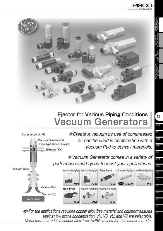
Ejector for Various Piping ConditionsVacuum Generators
●Creating vacuum by use of compressed air can be used in combination with a
Vacuum Pad to convey materials.
●Vacuum Generator comes in a variety of performance and types to meet your applications.
Compressed air (P)
Vacuum Generator VU(Pipe Type Union Straight)
Exhaust (EX)
Vacuum (V)
Vacuum Tube
Vacuum Pad
Work-piece
Valve Direct Mounting Type Valve Direct Mounting Type Pipe Type Small-seized Pipe Type Blow-Off Mechanism Equipped Type
Box Type Vacuum Pad Direct Mounting Vacuum Pad Direct Mounting
VH VS VU VUM VY
VB VM VC
For the applications requiring copper alloy free material and countermeasures against low ozone concentration, VH, VS, VU, and VC are selectable.
Metal parts material is copper alloy free. HNBR is used for seal rubber material.
Vacuum Generator SeriesVacuum Generator VH,VS,VU,VUM,VB,VM,VC,VY
VH · VS
53
VU
VB
VM · VC
VY
VUM
VAC
UU
M
GEN
ERA
TOR ■ Characteristicss
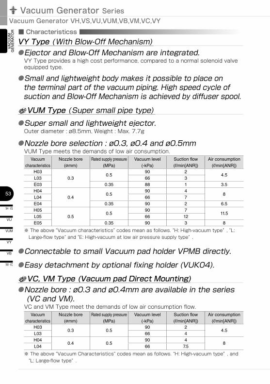
●Ejector and Blow-Off Mechanism are integrated.VY Type provides a high cost performance, compared to a normal solenoid valve equipped type.
●Small and lightweight body makes it possible to place on the terminal part of the vacuum piping. High speed cycle of suction and Blow-Off Mechanism is achieved by diffuser spool.
VY Type ( With Blow-Off Mechanism)
●Super small and lightweight ejector.Outer diameter : ø8.5mm, Weight : Max. 7.7g
VUM Type ( Super small pipe type)
●Nozzle bore selection : ø0.3, ø0.4 and ø0.5mmVUM Type meets the demands of low air consumption.
Vacuum characteristics
Nozzle bore(ømm)
Rated supply pressure(MPa)
Vacuum level(-kPa)
Suction flow(l/min[ANR])
Air consumption(l/min[ANR])
H030.3
0.590 2
4.5L03 66 3E03 0.35 88 1 3.5H04
0.40.5
90 48
L04 66 7E04 0.35 90 2 6.5H05
0.50.5
90 711.5
L05 66 12E05 0.35 90 3 8
※ The above “Vacuum characteristics” codes mean as follows. “H: High-vacuum type” , “L: Large-flow type” and “E: High-vacuum at low air pressure supply type” .
●Connectable to small Vacuum pad holder VPMB directly.●Easy detachment by optional fixing holder (VUK04).
VC, VM Type (Vacuum pad Direct Mounting)●Nozzle bore : ø0.3 and ø0.4mm are available in the series
(VC and VM).VC and VM Type meet the demands of low air consumption flow.
Vacuum characteristics
Nozzle bore(ømm)
Rated supply pressure(MPa)
Vacuum level(-kPa)
Suction flow(l/min[ANR])
Air consumption(l/min[ANR])
H030.3 0.5
90 24.5
L03 66 4H04
0.4 0.590 4
8L04 66 7.5
※ The above “Vacuum Characteristics” codes mean as follows. “H: High-vacuum type” , and “L: Large-flow type” .
54
VN
VZ
VQ
VX
VJ
VK
VG
VM · VC
VB
VU
VH · VS
VY
VUM
VRL
VAC
UU
M
GEN
ERA
TOR
EXTERNAL VACUUM CONTROLLER
VAC
UU
MPA
DVACUUM
ACCESSORIES
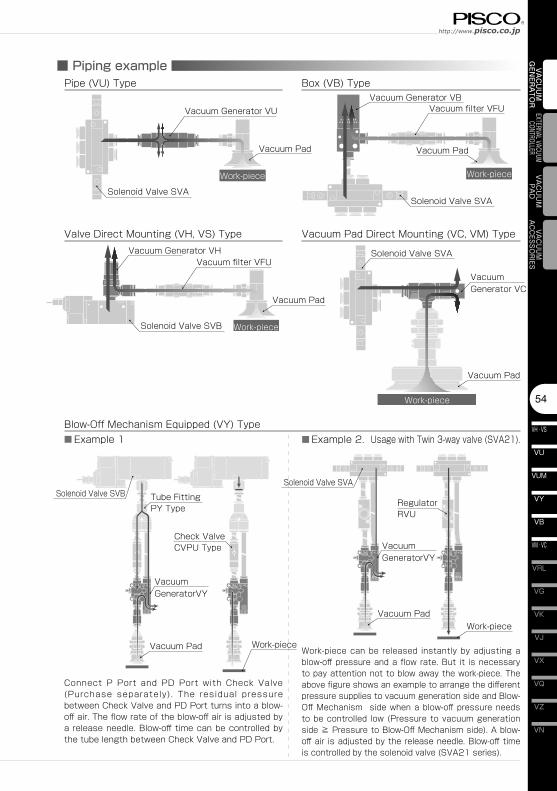
■ Piping examplePipe (VU) Type Box (VB) Type
Valve Direct Mounting (VH, VS) Type Vacuum Pad Direct Mounting (VC, VM) Type
Vacuum Pad
Solenoid Valve SVA
Work-piece
Work-piece
Work-piece
Work-piece
Vacuum Pad
Vacuum Pad
Vacuum Pad
Solenoid Valve SVA
Solenoid Valve SVB
Vacuum filter VFU
Vacuum filter VFUVacuum Generator VH
Vacuum Generator VUVacuum Generator VB
Vacuum Generator VC
Blow-Off Mechanism Equipped (VY) Type
Vacuum Pad
Solenoid Valve SVB Tube Fitting PY Type
Work-piece
Vacuum GeneratorVY
Solenoid Valve SVA
Check Valve CVPU Type
Vacuum Pad
Solenoid Valve SVA
Work-piece
Vacuum GeneratorVY
RegulatorRVU
■ Example 1 ■ Example 2. Usage with Twin 3-way valve (SVA21).
Connect P Port and PD Port with Check Valve (Purchase separately). The residual pressure between Check Valve and PD Port turns into a blow-off air. The flow rate of the blow-off air is adjusted by a release needle. Blow-off time can be controlled by the tube length between Check Valve and PD Port.
Work-piece can be released instantly by adjusting a blow-off pressure and a flow rate. But it is necessary to pay attention not to blow away the work-piece. The above figure shows an example to arrange the different pressure supplies to vacuum generation side and Blow-Off Mechanism side when a blow-off pressure needs to be controlled low (Pressure to vacuum generation side ≧ Pressure to Blow-Off Mechanism side). A blow-off air is adjusted by the release needle. Blow-off time is controlled by the solenoid valve (SVA21 series).
Vacuum Generator SeriesVacuum Generator VH,VS,VU,VUM,VB,VM,VC,VY
VH · VS
55
VU
VB
VM · VC
VY
VUM
VAC
UU
M
GEN
ERA
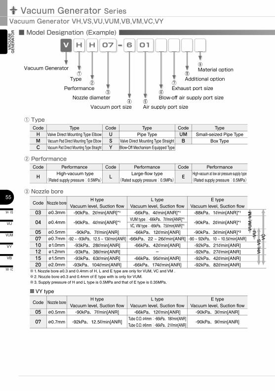
TOR ■ Model Designation (Example)
HV 07 6
Vacuum Generator
④Vacuum port size
①Type
③Nozzle diameter
① Type
H
②Performance
01
⑤Air supply port size
⑦Exhaust port size
② Performance
③ Nozzle bore
CodeHMC
TypeValve Direct Mounting Type ElbowVacuum Pad Direct Mounting Type ElbowVacuum Pad Direct Mounting Type Straight
CodeUSY
TypePipe Type
Valve Direct Mounting Type StraightBlow-Off Mechanism Equipped Type
CodeUMB
TypeSmall-seized Pipe Type
Box Type
Code
H
Performance High-vacuum type
(Rated supply pressure:0.5MPa)
Code
L
PerformanceLarge-flow type
(Rated supply pressure:0.5MPa)
Code
E
PerformanceHigh-vacuum at low air pressure supply type
(Rated supply pressure:0.5MPa)
Code
03
04
050710121520
Nozzle bore
ø0.3mm
ø0.4mm
ø0.5mmø0.7mmø1.0mmø1.2mmø1.5mmø2.0mm
H typeVacuum level, Suction flow
-90kPa、2l/min[ANR]*¹
-90kPa、4l/min[ANR]*¹
-90kPa、7l/min[ANR]-92 ~ -93kPa、12.5 ~ 13l/min[ANR]
-93kPa、28l/min[ANR]-93kPa、38l/min[ANR]-93kPa、63l/min[ANR]-93kPa、104l/min[ANR]
L typeVacuum level, Suction flow
-66kPa、4l/min[ANR]*¹VUM type:-66kPa、7l/min[ANR]*¹VC, VM type:-66kPa、7.5l/min[ANR]*¹
-66kPa、12l/min[ANR]-66kPa、22 ~ 26l/min[ANR]
-66kPa、42l/min[ANR]–
-66kPa、95l/min[ANR]-66kPa、174l/min[ANR]
E typeVacuum level, Suction flow
-88kPa、1l/min[ANR]*¹
-90kPa、2l/min[ANR]*¹
-90kPa、3l/min[ANR]*²-90 ~ 92kPa、10 ~ 10.5l/min[ANR]
-92kPa、21l/min[ANR]-92kPa、27l/min[ANR]-92kPa、42l/min[ANR]-92kPa、82l/min[ANR]
※1. Nozzle bore ø0.3 and 0.4mm of H, L and E type are only for VUM, VC and VM .※2. Nozzle bore ø0.3 and 0.4mm of E type with is only for VUM.※3. Supply pressure of H and L type is 0.5MPa and that of E type is 0.35MPa.
⑧Additional option
⑨Material option
■ VY type
Code Nozzle boreH type
Vacuum level, Suction flowL type
Vacuum level, Suction flowE type
Vacuum level, Suction flow05 ø0.5mm -90kPa、7l/min[ANR] -66kPa、12l/min[ANR] -90kPa、3l/min[ANR]
07 ø0.7mm -92kPa、12.5l/min[ANR]Tube O.D. ø4mm:-66kPa、18l/min[ANR]Tube O.D. ø6mm:-66kPa、21l/min[ANR]
-90kPa、9l/min[ANR]
⑥Blow-off air supply port size
④
①
③
②
⑤
⑦
⑧
⑥
VUM
, VM
VUVH
, VS VC
56
VN
VZ
VQ
VX
VJ
VK
VG
VM · VC
VB
VU
VH · VS
VY
VUM
VRL
VAC
UU
M
GEN
ERA
TOR
EXTERNAL VACUUM CONTROLLER
VAC
UU
MPA
DVACUUM
ACCESSORIES
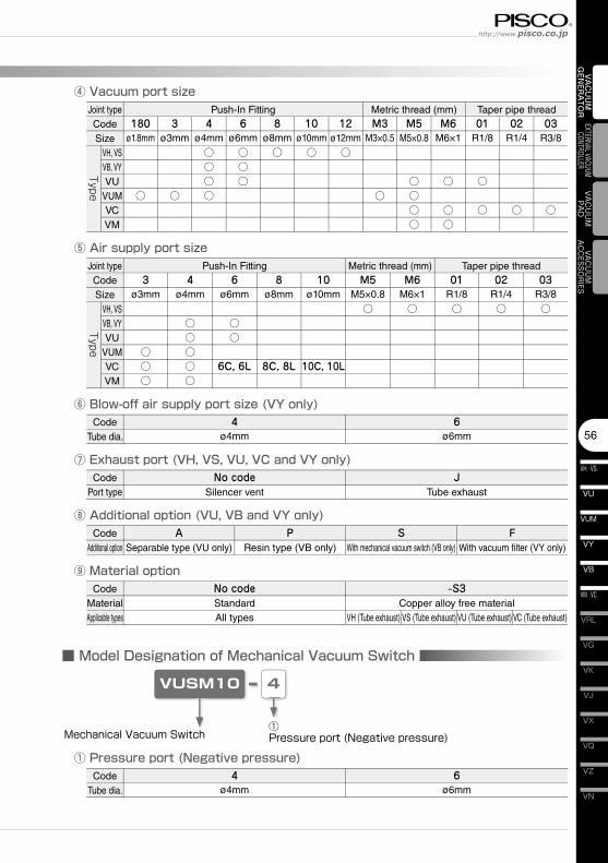
④ Vacuum port size
⑤ Air supply port size
⑦ Exhaust port (VH, VS, VU, VC and VY only)
Joint typeCodeSize
VH, VS VB, VY VU VUM VC VM
180ø1.8mm
○
Push-In Fitting Metric thread (mm) Taper pipe thread
Joint typeCodeSize
VH, VS VB, VY VU VUM VC VM
3ø3mm
○○○
Push-In Fitting Metric thread (mm) Taper pipe thread
CodePort type
No codeSilencer vent
JTube exhaust
⑧ Additional option (VU, VB and VY only)Code
Additional optionA
Separable type (VU only)S
With mechanical vacuum switch (VB only)
3ø3mm
○
4ø4mm
○○○○
6ø6mm
○○○
8ø8mm
○
10ø10mm
○
12ø12mm
○
M3M3×0.5
○
M5M5×0.8
○○○○
M6M6×1
○
○○
01R1/8
○
○
02R1/4
○
03R3/8
○
4ø4mm
○○○○○
6ø6mm
○○
6C, 6L
8ø8mm
8C, 8L
10ø10mm
10C, 10L
M5M5×0.8
○
M6M6×1
○
01R1/8
○
02R1/4
○
03R3/8
○
⑨ Material optionCode
MaterialApplicable types
No code -S3StandardAll types
Copper alloy free materialVH (Tube exhaust) VS (Tube exhaust) VU (Tube exhaust) VC (Tube exhaust)
⑥ Blow-off air supply port size (VY only)Code
Tube dia.4
ø4mm6
ø6mm
TypeType
PResin type (VB only)
FWith vacuum filter (VY only)
■ Model Designation of Mechanical Vacuum Switch
4VUSM10
Mechanical Vacuum Switch①Pressure port (Negative pressure)
① Pressure port (Negative pressure)Code
Tube dia.4
ø4mm6
ø6mm
Vacuum Generator SeriesVacuum Generator VH,VS,VU,VUM,VB,VM,VC,VY
VH · VS
57
VU
VB
VM · VC
VY
VUM
VAC
UU
M
GEN
ERA
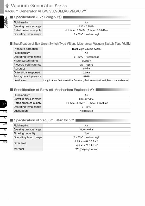
TOR ■ Specification (Excluding VY))
■ Specification of Box Union Switch Type VB and Mechanical Vacuum Switch Type VUSM
Fluid mediumOperating pressure rangeRated pressure supplyOperating temp. range
Air
0.15 ~ 0.7MPa
H, L type:0.5MPa(E type:0.35MPa)0 ~ 60°C(No freezing)
Pressure detectionFluid mediumOperating temp. rangeMicro switch ratingPressure setting rangeAccuracyDifferential responseFactory default pressureLead wire
Diaphragm to Micro switch
Air
0 ~ 60°C(No freezing)3A 250V
-20 ~ -66kPa
±5kPa
22kPa
-53kPa
Length: About 300mm (White: Common, Red: Normally closed, Black: Normally open)
■ Specification of Blow-off Mechanism Equipped VYFluid mediumOperating pressure rangeRated pressure supplyOperating temp. rangeLubrication
Air
0.3 ~ 0.7MPa
H, L type:0.5MPa(E type:0.35MPa)5 ~ 50°C
Not required
■ Specification of Vacuum Filter for VYFluid mediumOperating pressure rangeFiltering capacityOperating temp. range
Filter area
Material
Air
-100 ~ 0kPa
10µm
0 ~ 60°C(No freezing)Joint size 44:0.8cm2
Joint size 66:1.1cm2
PVF (Polyvinyl formal)
58
VN
VZ
VQ
VX
VJ
VK
VG
VM · VC
VB
VU
VH · VS
VY
VUM
VRL
VAC
UU
M
GEN
ERA
TOR
EXTERNAL VACUUM CONTROLLER
VAC
UU
MPA
DVACUUM
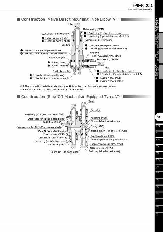
ACCESSORIES❶:Elastic sleeve (NBR)
Sealock- coating
Tube
Release ring (POM)
Lock-claws (Stainless steel)
❶:O-ring (NBR)
Tube end
Resin body (PBT)
❶:Metallic body (Nickel-plated brass)
❶:Guide ring (Nickel-plated brass)
■ Construction (Valve Direct Mounting Type Elbow: VH)
Exhaust body (Aluminum)
❶:Nozzle (Nickel-plated brass)
❶:Diffuser (Nickel-plated brass)
Y-packing (NBR)
Release needle (SUS303 equivalent steel)
Tube
Resin body (15% glass contained PBT)
■ Construction (Blow-Off Mechanism Equipped Type: VY)
Silencer element (PVF)
Sleeve (Nickel-plated brass)
Cartridge
End plug (Nickel-plated brass)
Upper stopper (Nickel-plated brass)
Plug (Nickel-plated brass) Nozzle piston (Nickel-plated brass)
Diffuser spool (Nickel-plated brass)
Spool packing (HNBR)
Diffuser spring (Stainless steel)Guide ring (Nickel-plated brass)
Elastic sleeve (NBR)
Release ring (POM)
O-ring (NBR)
Locknut (Aluminum)
Spring pin (Stainless steel)
Lock-claws (Stainless steel)
❷:Diffuser (Special stainless steel ※2)
❷:Metallic body (Special stainless steel ※2)
❷:O-ring (HNBR)
❷:Nozzle (Special stainless steel ※2)❷:Elastic sleeve (HNBR)
❷:Guide ring (Special stainless steel ※2)
❶:Guide ring (Nickel-plated brass)❷:Guide ring (Special stainless steel ※2)
❶:Elastic sleeve (NBR)❷:Elastic sleeve (HNBR)
Lock-claws (Stainless steel)
Release ring (POM)
Tube
Tube End
※ 1. The above ❶ material is for standard type. ❷ is for the type of copper alloy free material.※ 2. Performance of corrosion resistance is equal to SUS303.
Vacuum Generator SeriesVacuum Generator VH,VS,VU,VUM,VB,VM,VC,VY
VH · VS
59
VU
VB
VM · VC
VY
VUM
VAC
UU
M
GEN
ERA
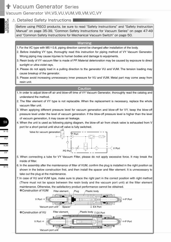
TOR Detailed Safety Instructions
Before using PISCO products, be sure to read “Safety Instructions” and “Safety Instruction Manual” on page 35-39, “Common Safety Instructions for Vacuum Series” on page 47-49 and “Common Safety Instructions for Mechanical Vacuum Switch” on page 50.
Warning1. For the VC type with M5×0.8, piping direction cannot be changed after installation of the body.
2. Before installing VY type, thoroughly read this instruction for piping method of VY Vacuum Generator.
Wrong piping may cause injuries to human bodies and damage to equipments.
3. Resin body of VY vacuum filter is made of PP. Material deterioration may be caused by exposure to direct
sunlight or ultra-violet rays.
4. Please do not apply load in a pulling direction to the generator VU and VUM. The tension loading may
cause breakup of the generator.
5. Please avoid increasing unnecessary inner pressure for VU and VUM. Metal part may come away from
resin unit.
Caution
●Construction of VUM
5. When connecting a tube for VY Vacuum Filter, please do not apply excessive force. It may break the
inside of filter.
6. In the assembly after the maintenance of filter of VUM, confirm the plug is installed in the right position as
shown in the below construction first, and then install the spacer and filter element. It is unnecessary to
take out the plug at the maintenance.
7. In case of VU and VUM type, make sure to place the right part in the correct position with right method
(There must not be space between the resin body and the vacuum port unit) at the filter element
maintenance. Otherwise, the satisfactory product performance cannot be obtained.
●Construction of VU
1. In order to adjust blow-off air and blow-off time of VY Vacuum Generator, thoroughly read the catalog and
understand the method.
2. The filter element of VY type is not replacable. When the replacement is necessary, replace the whole
vacuum filter unit.
3. When applying different pressure level for vacuum generation and blow-off for VY, keep the blow-off
pressure level under the level of vacuum generation. If the blow-off pressure level is higher than the level
of vacuum generation, it may cause air leakage.
4. When the unit is used as following piping diagram, the blow-off air from check valve is exhausted from V
port for a short period until shut-off valve is fully switched.
Valve for vacuum generationP Port
PD PortV Port
V Port ⇒
⇒
P Port
⇒
EX Port
Plug
Spacer
Filter element Plastic body
Vacuum port unit
V Port ⇒
⇒
P Port
⇒ EX PortFilter element Plastic body
Vacuum port unit
60
VN
VZ
VQ
VX
VJ
VK
VG
VM · VC
VB
VU
VH · VS
VY
VUM
VRL
VAC
UU
M
GEN
ERA
TOR
EXTERNAL VACUUM CONTROLLER
VAC
UU
MPA
DVACUUM
ACCESSORIES
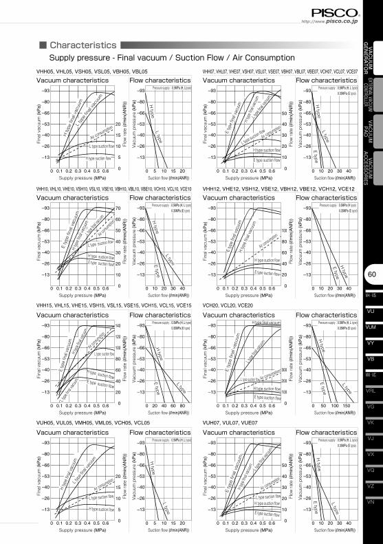
■ Characteristics
0 0 5 10 15 20
–13
–26
–40
–53
–66
–80
–93
–13
–26
–40
–53
–66
–80
–93
0.1 0.2 0.3 0.4 0.5 0.6
Supply pressure (MPa) Suction flow (l/min(ANR))
Fina
l vac
uum
(kP
a)
Vacu
um p
ress
ure
(kP
a)
Flow
rate
(l/m
in(A
NR
))
VHH05, VHL05, VSH05, VSL05, VBH05, VBL05
Vacuum characteristics Flow characteristics
H ty
pe fi
nal v
acuu
m
H type suction flow
L type suction flow
Air consumptionL typ
e fin
al va
cuum
0
5
10
15
20
H type
L type
0 0 10 20 30
–13
–26
–40
–53
–66
–80
–93
–13
–26
–40
–53
–66
–80
–93
0.1 0.2 0.3 0.4 0.5 0.6
Supply pressure (MPa) Suction flow (l/min(ANR))
Fina
l vac
uum
(kP
a)
Vacu
um p
ress
ure
(kP
a)
Flow
rate
(l/m
in(A
NR
))
VHH07, VHL07, VHE07, VSH07, VSL07, VSE07, VBH07, VBL07, VBE07, VCH07, VCL07, VCE07
Vacuum characteristics Flow characteristics
0
10
20
30
40
50
40
H type
E type
L type
H typ
e fina
l vac
uum
L type
final v
acuum
E typ
e fin
al va
cuum
H type suction flow
E type suction flow
L type suction flowAir consumption
Pressure supply:0.5MPa (H, L type)0.35MPa (E type)
0 0 10 20 30 40
–13
–26
–40
–53
–66
–80
–93
–13
–26
–40
–53
–66
–80
–93
0.1 0.2 0.3 0.4 0.5 0.6
Supply pressure (MPa) Suction flow (l/min(ANR))
Fina
l vac
uum
(kP
a)
Vacu
um p
ress
ure
(kP
a)
Flow
rate
(l/m
in(A
NR
))
VHH10, VHL10, VHE10, VSH10, VSL10, VSE10, VBH10, VBL10, VBE10, VCH10, VCL10, VCE10
Vacuum characteristics Flow characteristics
0
10
20
30
40
50
60
70
H type
E type
L type
H typ
e fina
l vac
uum
L type
final va
cuum
E ty
pe fi
nal v
acuu
m
H type suction flowE type suction flow
L type suction flowAir c
onsum
ption
Pressure supply:0.5MPa (H, L type)0.35MPa (E type)
0 0 10 20 30 40
–13
–26
–40
–53
–66
–80
–93
–13
–26
–40
–53
–66
–80
–93
0.1 0.2 0.3 0.4 0.5 0.6
Supply pressure (MPa) Suction flow (l/min(ANR))
Fina
l vac
uum
(kP
a)
Vacu
um p
ress
ure
(kP
a)
Flow
rate
(l/m
in(A
NR
))
VHH12, VHE12, VSH12, VSE12, VBH12, VBE12, VCH12, VCE12
Vacuum characteristics Flow characteristics
0
20
40
60
80
100
H type
E type
H typ
e fin
al va
cuum
E typ
e fin
al va
cuum
H type suction flow
E type suction flow
Air consumption
Pressure supply:0.5MPa (H type)0.35MPa (E type)
0 0 20 40 60 80
–13
–26
–40
–53
–66
–80
–93
–13
–26
–40
–53
–66
–80
–93
0.1 0.2 0.3 0.4 0.5 0.6
Supply pressure (MPa) Suction flow (l/min(ANR))
Fina
l vac
uum
(kP
a)
Vacu
um p
ress
ure
(kP
a)
Flow
rate
(l/m
in(A
NR
))
VHH15, VHL15, VHE15, VSH15, VSL15, VSE15, VCH15, VCL15, VCE15
Vacuum characteristics Flow characteristics
0
20
40
60
80
100
120
140
H type
E type
L type
H typ
e fina
l vac
uum
E ty
pe fi
nal v
acuu
m
H type suction flowE type suction flow
Air cons
umption
L typ
e fina
l vacu
um
L type suction flow
Pressure supply:0.5MPa (H, L type)0.35MPa (E type)
0 0 5 10 15 20
–13
–26
–40
–53
–66
–80
–93
–13
–26
–40
–53
–66
–80
–93
0.1 0.2 0.3 0.4 0.5 0.6
Supply pressure (MPa) Suction flow (l/min(ANR))
Fina
l vac
uum
(kP
a)
Vacu
um p
ress
ure
(kP
a)
Flow
rate
(l/m
in(A
NR
))
VUH05, VUL05, VMH05, VML05, VCH05, VCL05
Vacuum characteristics Flow characteristics
0
5
10
15
20
H type
L type
Pressure supply:0.5MPa (H, L type)
H typ
e fin
al va
cuum
L typ
e fina
l vac
uum
H type suction flow
L type suction flowAir consumption
0 0 10 20 30 40
–13
–26
–40
–53
–66
–80
–93
–13
–26
–40
–53
–66
–80
–93
0.1 0.2 0.3 0.4 0.5 0.6
Supply pressure (MPa) Suction flow (l/min(ANR))
Fina
l vac
uum
(kP
a)
Vacu
um p
ress
ure
(kP
a)
Flow
rate
(l/m
in(A
NR
))
VUH07, VUL07, VUE07
Vacuum characteristics Flow characteristics
0
10
20
30
40
50
H type
E type
L type
Pressure supply:0.5MPa (H, L type)0.35MPa (E type)
H typ
e fina
l vac
uum
L type
final v
acuum
E ty
pe fi
nal v
acuu
m
H type suction flow
E type suction flow
L type suction flow
Air consumption
Pressure supply:0.5MPa (H, Ltype)
0 0 50 100 150
–13
–26
–40
–53
–66
–80
–93
–13
–26
–40
–53
–66
–80
–93
0.1 0.2 0.3 0.4 0.5 0.6
Supply pressure (MPa) Suction flow (l/min(ANR))
Fina
l vac
uum
(kP
a)
Vacu
um p
ress
ure
(kP
a)
Flow
rate
(l/m
in(A
NR
))
VCH20, VCL20, VCE20
Vacuum characteristics Flow characteristics
0
100
200
300
H type
E type
L type
H type final vacuum
E ty
pe fi
nal v
acuu
m
H type suction flow
E type suction flow
Air consumption
L typ
e fina
l vacu
um
L type suction flow
Pressure supply:0.5MPa (H, L type)0.35MPa (E type)
Supply pressure - Final vacuum / Suction Flow / Air Consumption
Vacuum Generator SeriesVacuum Generator VH,VS,VU,VUM,VB,VM,VC,VY
VH · VS
61
VU
VB
VM · VC
VY
VUM
VAC
UU
M
GEN
ERA
TOR ■ Characteristics
0
1
7
6
5
4
3
2
8
9
10
11
12
1 2 3 4 5 6 7Vacuum volume (l)
Arr
ival
tim
e (s
ec)
VHH 05VSH 05VBH 05
0
1
7
6
5
4
3
2
8
9
10
11
12
1 2 3 4 5 6 7Vacuum volume (l)
Arr
ival
tim
e (s
ec)
0
1
7
6
5
4
3
2
8
9
10
11
12
1 2 3 4 5 6 7Vacuum volume (l)
Arr
ival
tim
e (s
ec)
0
1
7
6
5
4
3
2
8
9
10
11
12
1 2 3 4 5 6 7Vacuum volume (l)
Arr
ival
tim
e (s
ec)
VUE 07
0
1
7
6
5
4
3
2
8
9
10
11
12
1 2 3 4 5 6 7Vacuum volume (l)
Arr
ival
tim
e (s
ec)
0
1
7
6
5
4
3
2
8
9
10
11
12
1 2 3 4 5 6 7Vacuum volume (l)
Arr
ival
tim
e (s
ec)
VHH 07VSH 07VBH 07
VHL 07VSL 07VBL 07
0
1
7
6
5
4
3
2
8
9
10
11
12
1 2 3 4 5 6 7Vacuum volume (l)
Arr
ival
tim
e (s
ec)
VUL 05 VUH 07 VUL 07
0
1
7
6
5
4
3
2
8
9
10
11
12
1 2 3 4 5 6 7Vacuum volume (l)
Arr
ival
tim
e (s
ec)
0
1
7
6
5
4
3
2
8
9
10
11
12
1 2 3 4 5 6 7Vacuum volume (l)
Arr
ival
tim
e (s
ec)
-80k
Pa
-66k
Pa
-86k
Pa
-80k
Pa
-13kPa
-26kPa
-40kPa
-53k
Pa-60k
Pa
-66k
Pa
-13kPa
-26kPa
-40k
Pa
-53k
Pa
-66k
Pa
-86k
Pa
-80k
Pa
-13kPa
-26k
Pa
-40k
Pa
-53k
Pa
-66k
Pa
-80k
Pa
-86k
Pa
-13kPa
-26kPa
-40kPa
-53kPa
-60k
Pa
-66k
Pa
-13kPa
-26kPa
-40k
Pa
-53k
Pa
-66k
Pa
-86k
Pa
-13kPa
-26kPa
-40k
Pa
-53k
Pa
-60k
Pa
-66k
Pa
-13kPa
-26k
Pa
-40k
Pa
-53k
Pa
-13kPa
-26kPa
-40k
Pa-53k
Pa
-60k
Pa
-66k
Pa
-86k
Pa
-80k
Pa
-13kPa
-26k
Pa
-40k
Pa
-53k
Pa
-66k
Pa
VHL 05VSL 05VBL 05 VUH 05
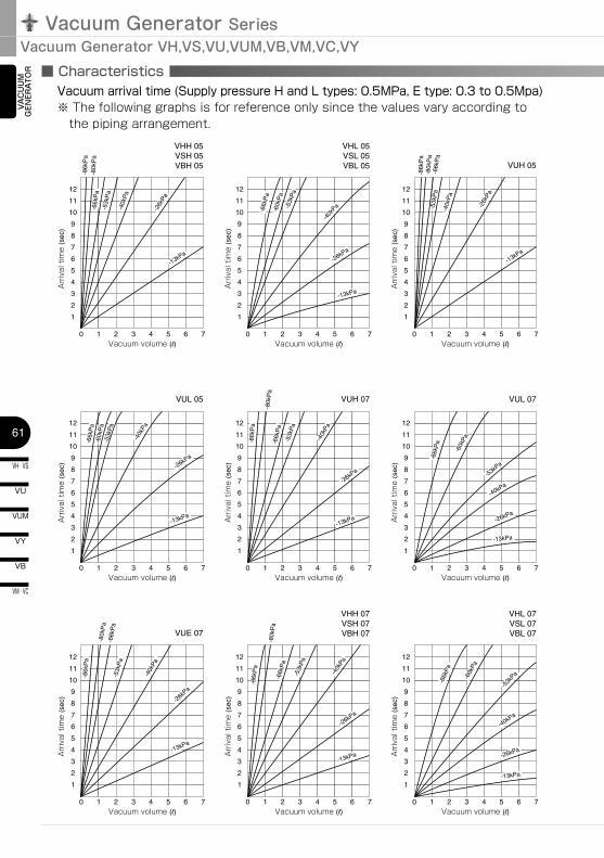
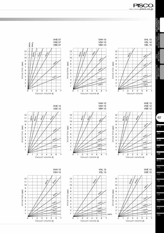
Vacuum arrival time (Supply pressure H and L types: 0.5MPa, E type: 0.3 to 0.5Mpa)※ The following graphs is for reference only since the values vary according to
the piping arrangement.
62
VN
VZ
VQ
VX
VJ
VK
VG
VM · VC
VB
VU
VH · VS
VY
VUM
VRL
VAC
UU
M
GEN
ERA
TOR
EXTERNAL VACUUM CONTROLLER
VAC
UU
MPA
DVACUUM
ACCESSORIES
-13kPa
0
1
7
6
5
4
3
2
8
9
10
11
12
1 2 3 4 5 6 7Vacuum volume (l)
Arr
ival
tim
e (s
ec)
VHE 07VSE 07VBE 07
0
1
7
6
5
4
3
2
8
9
10
11
12
1 2 3 4 5 6 7Vacuum volume
Arr
ival
tim
e (s
ec)
0
1
7
6
5
4
3
2
8
9
10
11
12
1 2 3 4 5 6 7Vacuum volume (l)
Arr
ival
tim
e (s
ec)
0
1
7
6
5
4
3
2
8
9
10
11
12
1 2 3 4 5 6 7Vacuum volume (l)
Arr
ival
tim
e (s
ec)
0
1
7
6
5
4
3
2
8
9
10
11
12
1 2 3 4 5 6 7Vacuum volume (l)
Arr
ival
tim
e (s
ec)
0
1
7
6
5
4
3
2
8
9
10
11
12
1 2 3 4 5 6 7Vacuum volume (l)
Arr
ival
tim
e (s
ec)
0
1
7
6
5
4
3
2
8
9
10
11
12
1 2 3 4 5 6 7Vacuum volume (l)
Arr
ival
tim
e (s
ec)
VHH 12VSH 12VBH 12
VHE 12VSE 12VBE 12
0
1
7
6
5
4
3
2
8
9
10
11
12
1 2 3 4 5 6 7Vacuum volume (l)
Arr
ival
tim
e (s
ec)
0
1
7
6
5
4
3
2
8
9
10
11
12
1 2 3 4 5 6 7Vacuum volume (l)
Arr
ival
tim
e (s
ec)
VHH 10VSH 10VBH 10
VHL 10VSL 10VBL 10
-13kPa-26kPa
-40kPa
-53kPa
-66k
Pa
-600
kPa
-650
kPa
-66k
Pa
-60kPa
-53kPa
-40kPa
-26kPa
-86k
Pa
-80k
Pa
-66kPa
53kPa
-40kPa
-26kPa
-13kPa
-13kPa
-26kPa
-40kPa
-53k
Pa
-66k
Pa
-80k
Pa
-86k
Pa
-13kPa
-26kPa
-40kPa
-53kPa
-66k
Pa
-80k
Pa
-86k
Pa
-13kPa
-26kPa
-40kPa
-53k
Pa
-66k
Pa
-80k
Pa
-86k
Pa
-13kPa
-26kPa
-40kPa
-53kPa
-60kPa
-66k
Pa
-13kPa
-26kPa
-40kPa
-53k
Pa
-66k
Pa
-80k
Pa
-86k
Pa
-13kPa
-26k
Pa
-40k
Pa
-53k
Pa
-66k
Pa
-80k
Pa
-86k
Pa
VHE 10VSE 10
VHE 15VSE 15
VHL 15VSL 15
VHH 15VSH 15
Vacuum Generator SeriesVacuum Generator VH,VS,VU,VUM,VB,VM,VC,VY
VH · VS
63
VU
VB
VM · VC
VY
VUM
VAC
UU
M
GEN
ERA
TOR ■ Characteristics
0
1
7
6
5
4
3
2
8
9
10
11
12
1 2 3 4 5 6 7Vacuum volume (l)
Arr
ival
tim
e (s
ec)
-13kPa-26kPa-40kPa
-53kPa-66kPa
-80kPa
-85kPa
VCH 20
0
1
7
6
5
4
3
2
8
9
10
11
12
1 2 3 4 5 6 7Vacuum volume (l)
Arr
ival
tim
e (s
ec)
-26kPa
-40kPa-53kPa
-66kPa
-80kPa
-85k
Pa
VCE 20
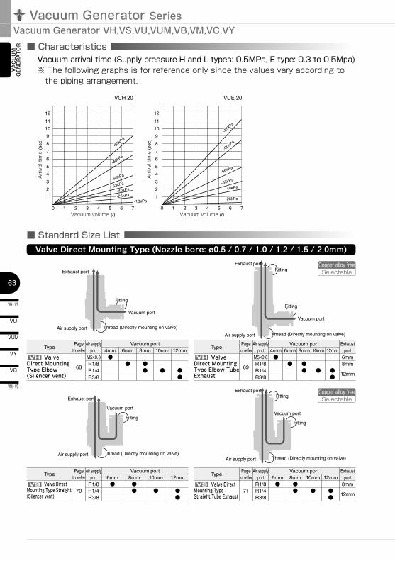
■ Standard Size ListValve Direct Mounting Type (Nozzle bore: ø0.5 / 0.7 / 1.0 / 1.2 / 1.5 / 2.0mm)
Air supply port Thread (Directly mounting on valve)
Fitting
Fitting
Vacuum port
Fitting
Air supply port Thread (Directly mounting on valve)
Vacuum port
Fitting
Exhaust port
Vacuum port
Air supply port
Fitting
Fitting
Thread (Directly mounting on valve)
Exhaust port
Exhaust port
Vacuum port
Exhaust port
Air supply port Thread (Directly mounting on valve)
Copper alloy freeSelectable
Copper alloy freeSelectable
Vacuum arrival time (Supply pressure H and L types: 0.5MPa, E type: 0.3 to 0.5Mpa)※ The following graphs is for reference only since the values vary according to
the piping arrangement.
TypePage
to referAir supply
portVacuum port
4mm 6mm 8mm 10mm 12mm
68
M5×0.8R1/8R1/4R3/8
●● ●
● ● ●●
TypePage
to referAir supply
portVacuum port
4mm
69
M5×0.8R1/8R1/4R3/8
●6mm
●
8mm
●●
10mm
●
12mm
●●
Exhaust port
6mm8mm
12mm
TypePage
to referAir supply
portVacuum port
6mm
70R1/8R1/4R3/8
●
TypePage
to referAir supply
portVacuum port
6mm
71R1/8R1/4R3/8
●
Exhaust port
8mm
12mm
8mm●●
10mm
●
12mm
●●
8mm●●
10mm
●
12mm
●●
VH Valve Direct Mounting Type Elbow (Silencer vent)
VH Valve Direct Mounting Type Elbow Tube Exhaust
VS Valve Direct Mounting Type Straight (Silencer vent)
VS Valve Direct Mounting Type Straight Tube Exhaust
64
VN
VZ
VQ
VX
VJ
VK
VG
VM · VC
VB
VU
VH · VS
VY
VUM
VRL
VAC
UU
M
GEN
ERA
TOR
EXTERNAL VACUUM CONTROLLER
VAC
UU
MPA
DVACUUM
ACCESSORIES
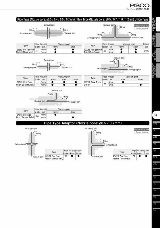
Pipe Type (Nozzle bore: ø0.3 / 0.4 / 0.5 / 0.7mm) / Box Type (Nozzle bore: ø0.5 / 0.7 / 1.0 / 1.2mm) Union Type
Fitting
Air supply port
Fitting
Vacuum portFitting
Fitting
Air supply port
Fitting
Exhaust port
Vacuum port
Exhaust port
Fitting
Air supply port
Fitting
Vacuum port
Exhaust port
Fitting
Air supply port
Fitting
Vacuum port
Exhaust port
Fitting
Air supply port
Fitting
Vacuum port
Exhaust port
Pipe Type Adaptor (Nozzle bore: ø0.5 / 0.7mm)Air supply port
Vacuum port
Fitting
Exhaust port
Vacuum port
Air supply port
Fitting
Fitting
Exhaust port
Copper alloy freeSelectable
Copper alloy freeSelectable
TypePage
to referAir supply
portVacuum port
4mm
744mm6mm
●●
TypePage
to referAir supply
portVacuum port
4mm●●
Exhaust port
6mm
6mm●●
6mm●●
TypePage
to referAir supply
portVacuum port
1.8mm
773mm4mm
●●
TypePage
to referAir supply
portVacuum port
4mm
864mm6mm
●6mm
●
TypePage
to referAir supply
portVacuum port
4mm
864mm6mm
●6mm
●
3mm●●
4mm●●
TypePage
to referAir supply port4mm
76 ●6mm●
TypePage
to referAir supply port4mm
76 ●6mm●
VU Pipe Type Union Straight (Silencer vent)
VU Pipe Type Union Straight Tube Exhaust 75
4mm6mm
VUM Pipe Type Union Straight(vent)
VB Box Type Union Vacuum Switch
VB Box Type Union
VU Pipe Type Adapter (Silencer vent)
VU Pipe Type Adapter Tube Exhaust
Vacuum Generator SeriesVacuum Generator VH,VS,VU,VUM,VB,VM,VC,VY
VH · VS
65
VU
VB
VM · VC
VY
VUM
VAC
UU
M
GEN
ERA
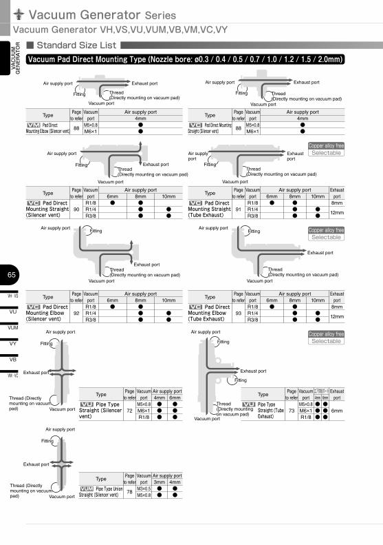
TOR ■ Standard Size List
Vacuum Pad Direct Mounting Type (Nozzle bore: ø0.3 / 0.4 / 0.5 / 0.7 / 1.0 / 1.2 / 1.5 / 2.0mm)
Thread (Directly mounting on vacuum pad)
Thread (Directly mounting on vacuum pad)
Thread (Directly mounting on vacuum pad)
Fitting
Thread (Directly mounting on vacuum pad)
Fitting
Thread (Directly mounting on vacuum pad)
Vacuum port
Fitting
Air supply port Exhaust port
Thread (Directly mounting on vacuum pad)
Fitting
Air supply port
Vacuum port
Exhaust port
Thread (Directly mounting on vacuum pad)
Vacuum port
Fitting
Air supply port
Exhaust port
Thread (Directly mounting on vacuum pad)
Fitting
Air supply port
Vacuum port
Exhaust port
Vacuum port
Air supply port
Exhaust port
Air supply port
Vacuum port
Exhaust port
Air supply port
Vacuum port
Fitting
Exhaust port
Vacuum port
Air supply port
Fitting
Fitting
Exhaust port
Thread (Directly mounting on vacuum pad)
Air supply port
Vacuum port
Fitting
Exhaust port
Copper alloy freeSelectable
Copper alloy freeSelectable
Copper alloy freeSelectable
TypePage
to referVacuum
portAir supply port
4mm
88M5×0.8M6×1
●●
TypePage
to referVacuum
portAir supply port
4mm
88M5×0.8M6×1
●●
TypePage
to referVacuum
portAir supply port
6mm
90R1/8R1/4R3/8
●
TypePage
to referVacuum
portAir supply port
6mm
91R1/8R1/4R3/8
●
Exhaust port
8mm
12mm
8mm●●●
10mm
●●
8mm●●●
10mm
●●
TypePage
to referVacuum
portAir supply port
6mm
92R1/8R1/4R3/8
●
TypePage
to referVacuum
portAir supply port
6mm
93R1/8R1/4R3/8
●
Exhaust port
8mm
12mm
8mm●●●
10mm
●●
8mm●●●
10mm
●●
TypePage
to referVacuum
portAir supply port4mm
72M5×0.8M6×1R1/8
●●●
TypePage
to referVacuum
portエア供給ポート4mm
73M5×0.8M6×1R1/8
●●●
Exhaust port
6mm
6mm●●●
6mm●●●
TypePage
to referVacuum
portAir supply port3mm
78M3×0.5M5×0.8
●●
4mm●●
VM Pad Direct Mounting Elbow (Silencer vent)
VC Pad Direct Mounting Straight (Silencer vent)
VC Pad Direct Mounting Straight (Silencer vent)
VC Pad Direct Mounting Straight (Tube Exhaust)
VC Pad Direct Mounting Elbow (Silencer vent)
VC Pad Direct Mounting Elbow (Tube Exhaust)
VU Pipe Type Straight (Silencer vent)
VU Pipe Type Straight (Tube Exhaust)
VUM Pipe Type Union Straight (Silencer vent)
66
VN
VZ
VQ
VX
VJ
VK
VG
VM · VC
VB
VU
VH · VS
VY
VUM
VRL
VAC
UU
M
GEN
ERA
TOR
EXTERNAL VACUUM CONTROLLER
VAC
UU
MPA
DVACUUM
ACCESSORIES
FittingFitting
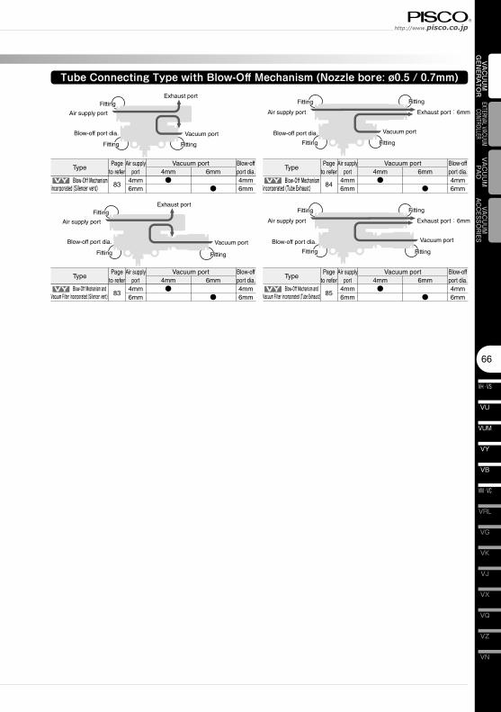
Tube Connecting Type with Blow-Off Mechanism (Nozzle bore: ø0.5 / 0.7mm)
Fitting
Air supply port
Fitting
Vacuum port
Fitting
Fitting
Air supply port
Fitting
Exhaust port:6mm
Vacuum port
Exhaust port
Blow-off port dia. Blow-off port dia.
FittingFitting Fitting
Air supply port
Fitting
Vacuum port
Fitting
Fitting
Air supply port
Fitting
Exhaust port:6mm
Vacuum port
Exhaust port
Blow-off port dia. Blow-off port dia.
TypePage
to referAir supply
port
834mm6mm
TypePage
to referAir supply
portVacuum port
4mm●
Blow-off port dia.4mm6mm
6mm
●
Vacuum port4mm●
Blow-off port dia.4mm6mm
6mm
● 844mm6mm
TypePage
to referAir supply
port
834mm6mm
TypePage
to referAir supply
portVacuum port
4mm●
Blow-off port dia.4mm6mm
6mm
●
Vacuum port4mm●
Blow-off port dia.4mm6mm
6mm
● 854mm6mm
VY Blow-Off Mechanism incorporated (Silencer vent)
VY Blow-Off Mechanism incorporated (Tube Exhaust)
VY Blow-Off Mechanism and Vacuum Filter incorporated (Silencer vent)
VY Blow-Off Mechanism and Vacuum Filter incorporated (Tube Exhaust)
Vacuum Generator SeriesVacuum Generator VH,VS,VU,VUM,VB,VM,VC,VY
VH · VS
67
VU
VB
VM · VC
VY
VUM
VAC
UU
M
GEN
ERA
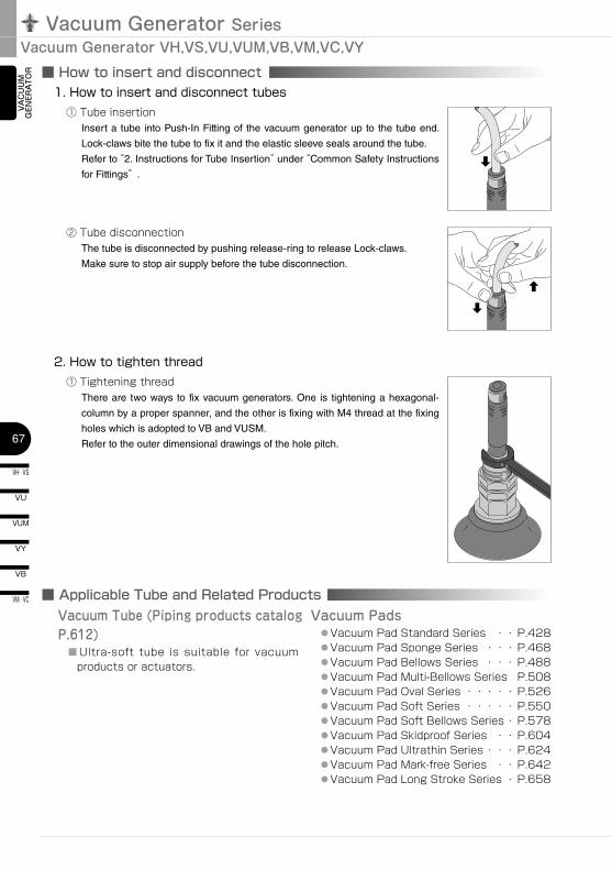
TOR ■ How to insert and disconnect
■ Applicable Tube and Related Products
1. How to insert and disconnect tubes① Tube insertion
Insert a tube into Push-In Fitting of the vacuum generator up to the tube end.
Lock-claws bite the tube to fix it and the elastic sleeve seals around the tube.
Refer to “2. Instructions for Tube Insertion” under “Common Safety Instructions
for Fittings” .
② Tube disconnectionThe tube is disconnected by pushing release-ring to release Lock-claws.
Make sure to stop air supply before the tube disconnection.
2. How to tighten thread① Tightening thread
There are two ways to fix vacuum generators. One is tightening a hexagonal-
column by a proper spanner, and the other is fixing with M4 thread at the fixing
holes which is adopted to VB and VUSM.
Refer to the outer dimensional drawings of the hole pitch.
Vacuum Tube (Piping products catalog P.612) ■ Ultra-soft tube is suitable for vacuum
products or actuators.
Vacuum Pads ● Vacuum Pad Standard Series ・・ P.428 ● Vacuum Pad Sponge Series ・・・ P.468 ● Vacuum Pad Bellows Series ・・・ P.488 ● Vacuum Pad Multi-Bellows Series P.508 ● Vacuum Pad Oval Series ・・・・・ P.526 ● Vacuum Pad Soft Series ・・・・・ P.550 ● Vacuum Pad Soft Bellows Series ・ P.578 ● Vacuum Pad Skidproof Series ・・ P.604 ● Vacuum Pad Ultrathin Series ・・・ P.624 ● Vacuum Pad Mark-free Series ・・ P.642 ● Vacuum Pad Long Stroke Series ・ P.658

68
VN
VZ
VQ
VX
VJ
VK
VG
VM · VC
VB
VU
VH · VS
VY
VUM
VRL
VAC
UU
M
GEN
ERA
TOR
EXTERNAL VACUUM CONTROLLER
VAC
UU
MPA
DVACUUM
ACCESSORIES
VH
Metric thread type
R
øDøP1
øP
2
C
E
L1HEXH
EXH
B
A
L2V
P
R
øD
øP1
øP
2
C
E
L1
H
B
A
L2
Valve Direct Mounting Type Elbow (Silencer vent)
Unit:mm
Model code
Tube O.D.øD
R A B L1 L2 øP1 øP2 C EHex.
H
Nozzle bore(mm)
Operating pressure(MPa)
Final vacuum
(-kPa)
Suction flow
(l/min(ANR))
Air consumption(l/min(ANR))
Weight(g)
CAD
file nameVHH05-4M5 4 M5×0.8 3.5 35 31.5 10.5 10 9.8 14.9 21.2 8
0.5
0.5
90 7 11.513 VH_05-4M5
VHH05-601
6R1/8 8 48 44
11.4 12.418.4
17 25.517
36.5
VH_-601VHH07-601 0.7
93
13 23 37
VHH10-601 1 28 4636.5
VHH12-601 1.2 38 70
VHH10-8018
12.414.4 18.1
28.41 28 46 38
VH_-801VHH12-801 1.2 38 70 37.5
VHH15-802R1/4 11
71.5 65.513.5
2228.9
22 1.5 63 10077 VH_15-802
VHH15-100210
14.817.6 20.2
31.2 79.5 VH_15-1002
VHH20-1002 99.6 93.5 15.1
2833.6
24 2 104 200
116 VH_20-1002
VHH20-1003 R3/8 12 100.6 94.2 15.8 126 VH_20-1003
VHH20-120212
R1/4 11 99.6 93.5 16.821 23.4 36.4
116 VH_20-1202
VHH20-1203 R3/8 12 100.6 94.2 17.5 126 VH_20-1203
VHL05-4M5 4 M5×0.8 3.5 35 31.5 10.5 10 9.8 14.9 21.2 80.5
0.5 66
12 11.513 VH_05-4M5
VHL05-6016
R1/8 8 48 4411.4 12.4
18.417 25.5
17
36.5VH_-601VHL07-601 0.7 26 23 37
VHL10-601 1 42 46 36
VHL07-8018
12.414.4 18.1
28.40.7 26 23 38.5
VH_-801VHL10-801 1 42 46 37.5
VHL15-802
R1/4 1171.5 65.5
13.522
28.922 1.5 95 100
75 VH_15-802
VHL15-1002 10 14.8 17.6 20.2 31.2 77.5 VH_15-1002
VHL15-1202 12 16.5 21 23.4 36.9 81.5 VHL15-1202
VHL20-100210
99.6 93.5 15.117.6
2820.2 33.6
24 2 174 200
116 VH_20-1002
VHL20-1003 R3/8 12 100.6 94.2 15.8 126 VH_20-1003
VHL20-120212
R1/4 11 99.6 93.5 16.821 23.4 36.4
116 VH_20-1202
VHL20-1203 R3/8 12 100.6 94.2 17.5 126 VH_20-1203
VHE07-6016
R1/8 8 48 4411.4 12.4
18.417 25.5
17
0.7
0.35 92
10.5 17 36.5VH_-601VHE10-601 1 21 34 37
VHE12-601 1.2 27 47 36.5
VHE10-8018
12.414.4 18.1
28.41 21 34 38.5
VH_-801VHE12-801 1.2 27 47 38
VHE15-802R1/4 11
71.5 65.513.5
2228.9
22 1.5 42 7078 VH_15-802
VHE15-100210
14.817.6 20.2
31.2 80 VH_15-1002
VHE20-1002 99.6 93.5 15.1
2833.6
24 2 82 150
116 VH_20-1002
VHE20-1003 R3/8 12 100.6 94.2 15.8 126 VH_20-1003
VHE20-120212
R1/4 11 99.6 93.5 16.821 23.4 36.4
116 VH_20-1202
VHE20-1203 R3/8 12 100.6 94.2 17.5 126 VH_20-1203
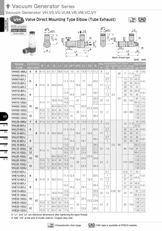
※ “L1” and “L2” are reference dimensions after tightening the taper thread.
CAD-2D & 3D- Chart
P.60
CAD-2D & 3D- CAD data is available at PISCO website.Characteristic chart page Chart
P.000
compliant
Vacuum Generator SeriesVacuum Generator VH,VS,VU,VUM,VB,VM,VC,VY
VH · VS
69
VU
VB
VM · VC
VY
VUM
VAC
UU
M
GEN
ERA
TOR VH
øD1øP1
C1
E
H
Metric thread type
R
øP
2øD
2
L1B
AC2
L2V
P
EXH
øD1øP1
C1
E
R
øD
2
L1
H
BA
C2
L2
øP
2
Valve Direct Mounting Type Elbow (Tube Exhaust)
Unit:mm
Model code
Tube O.D.øD1
Tube O.D.øD2
R A B L1 L2 øP1 øP2 C1 C2 EHex.H
Nozzle bore(mm)
Operating pressure
(MPa)
Final vacuum
(-kPa)
Suction flow
(l/min(ANR))
Air consumption(l/min(ANR))
Weight(g)
CAD
file nameVHH05-4M5J 4 6 M5×0.8 3.5 42.1 38.6 10.5 10 10 14.9 11.7 21.2 8
0.5
0.5
90 7 11.518 VH_05-4M5J
VHH05-601J
68 R1/8 8 58.4 54.4
11.4 12.418.4
1718.2
25.517
44.5
VH_-601JVHH07-601J 0.7
93
13 23 45.5
VHH10-601J 1 28 46 44.5
VHH12-601J 1.2 38 70 44
VHH10-801J8
12.414.4 18.1
28.41 28 46 45.5
VH_-801JVHH12-801J 1.2 38 70 46
VHH15-802J
12
R1/4 1176.9 70.9
13.522
23.3
28.922 1.5 63 100
92 VH_15-802J
VHH15-1002J10
14.817.6 20.2
31.2 94.5 VH_15-1002J
VHH20-1002J 89.4 83.3 15.1
2833.6
24 2 104 200
128 VH_20-1002J
VHH20-1003J R3/8 12 90.4 84 15.8 138 VH_20-1003J
VHH20-1202J12
R1/4 11 89.4 83.3 16.821 23.4 36.4
128 VH_20-1202J
VHH20-1203J R3/8 12 90.4 84 17.5 138 VH_20-1203J
VHL05-4M5J 4 6 M5×0.8 3.5 42.1 38.6 10.5 10 10 14.9 11.7 21.2 80.5
0.5 66
12 11.518 VH_05-4M5J
VHL05-601J6
8 R1/8 8 58.4 54.411.4 12.4
18.417
18.225.5
17
44.5VH_-601JVHL07-601J 0.7 26 23 45
VHL10-601J 1 42 46 44
VHL07-801J8
12.414.4 18.1
28.40.7 26 23 46
VH_-801JVHL10-801J 1 42 46 45
VHL15-802J
12
R1/4 1176.9 70.9
13.522
23.3
28.922 1.5 95 100
89.5 VH_15-802J
VHL15-1002J 10 14.8 17.6 20.2 31.2 93 VH_15-1002J
VHL15-1202J 12 16.5 21 23.4 36.9 96.5 VHL15-1202J
VHL20-1002J10
89.4 83.3 15.117.6
2820.2 33.6
24 2 174 200
128 VH_20-1002J
VHL20-1003J R3/8 12 90.4 84 15.8 138 VH_20-1003J
VHL20-1202J12
R1/4 11 89.4 83.3 16.821 23.4 36.4
128 VH_20-1202J
VHL20-1203J R3/8 12 90.4 84 17.5 138 VH_20-1203J
VHE07-601J6
8 R1/8 8 58.4 54.411.4 12.4
18.417
18.225.5
17
0.7
0.35 92
10.5 17 45VH_-601JVHE10-601J 1 21 34
44.5VHE12-601J 1.2 27 47
VHE10-801J8
12.414.4 18.1
28.41 21 34 46.5
VH_-801JVHE12-801J 1.2 27 47 45.5
VHE15-802J
12
R1/4 1176.9 70.9
13.522
23.3
28.922 1.5 42 70
92 VH_15-802J
VHE15-1002J10
14.817.6 20.2
31.2 95.5 VH_15-1002J
VHE20-1002J 89.4 83.3 15.1
2833.6
24 2 82 150
128 VH_20-1002J
VHE20-1003J R3/8 12 90.4 84 15.8 138 VH_20-1003J
VHE20-1202J12
R1/4 11 89.4 83.3 16.821 23.4 36.4
128 VH_20-1202J
VHE20-1203J R3/8 12 90.4 84 17.5 138 VH_20-1203J
※ “L1” and “L2” are reference dimensions after tightening the taper thread.※ Add “-S3” at the end of model code for “Copper alloy free” .
CAD-2D & 3D- Chart
P.60
compliantCopper alloy free
Selectable
CAD-2D & 3D- CAD data is available at PISCO website.Characteristic chart page Chart
P.000
70
VN
VZ
VQ
VX
VJ
VK
VG
VM · VC
VB
VU
VH · VS
VY
VUM
VRL
VAC
UU
M
GEN
ERA
TOR
EXTERNAL VACUUM CONTROLLER
VAC
UU
MPA
DVACUUM
ACCESSORIES
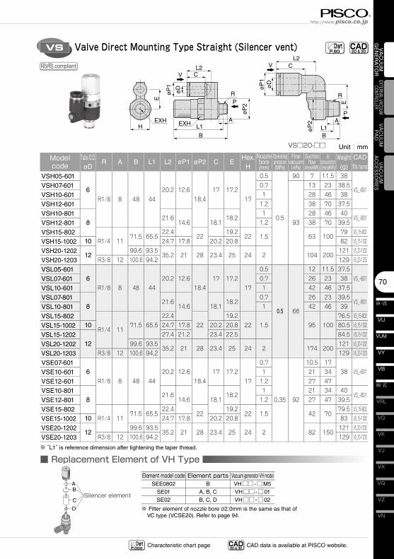
Valve Direct Mounting Type Straight (Silencer vent)VS CAD-2D & 3D- Chart
P.60
Silencer element
AB
C
D
■ Replacement Element of VH Type
RøD
øP
1
øP
2
CV
E
L1HEXH EXH
B
A
L2 V
P
P
E
øP
1
øP
2
øD
BL1
A
R
CL2
VS□20-□□
※ Filter element of nozzle bore ø2.0mm is the same as that of VC type (VCSE20). Refer to page 94.
Element model codeSEE0802
SE01SE02
Vacuum generator VH modelVH□□ -□M5VH□□ -□01VH□□ -□02
Element partsB
A, B, CB, C, D
Unit:mm
Model code
Tube O.D.øD
R A B L1 L2 øP1 øP2 C EHex.
H
Nozzle bore(mm)
Operating pressure(MPa)
Final vacuum
(-kPa)
Suction flow
(l/min(ANR))
Air consumption(l/min(ANR))
Weight(g)
CAD
file nameVSH05-601
6R1/8 8 48 44
20.2 12.618.4
17 17.217
0.5
0.5
90 7 11.5 38
VS_-601VSH07-601 0.7
93
13 23 38.5
VSH10-601 1 28 46 38
VSH12-601 1.2 38 70 37.5
VSH10-8018
21.614.6 18.1
18.21 28 46 40
VS_-801VSH12-801 1.2 38 70 39.5
VSH15-802R1/4 11
71.5 65.522.4
2219.2
22 1.5 63 10079 VS_15-802
VSH15-1002 10 24.7 17.8 20.2 20.8 82 VS_15-1002
VSH20-120212
99.6 93.535.2 21 28 23.4 25 24 2 104 200
121 VS_20-1202
VSH20-1203 R3/8 12 100.6 94.2 129 VS_20-1203
VSL05-6016
R1/8 8 48 4420.2 12.6
18.417 17.2
17
0.5
0.5 66
12 11.5 37.5VS_-601VSL07-601 0.7 26 23 38
VSL10-601 1 42 46 37.5
VSL07-8018
21.614.6 18.1
18.20.7 26 23 39.5
VS_-801VSL10-801 1 42 46 39
VSL15-802
R1/4 1171.5 65.5
22.422
19.222 1.5 95 100
76.5 VS_15-802
VSL15-1002 10 24.7 17.8 20.2 20.8 80.5 VS_15-1002
VSL15-120212
27.4 21.2 23.4 22.5 84.5 VSL15-1202
VSL20-1202 99.6 93.535.2 21 28 23.4 25 24 2 174 200
121 VS_20-1202
VSL20-1203 R3/8 12 100.6 94.2 129 VS_20-1203
VSE07-6016
R1/8 8 48 4420.2 12.6
18.417 17.2
17
0.7
0.35 92
10.5 1738 VS_-601VSE10-601 1 21 34
VSE12-601 1.2 27 47
VSE10-8018
21.614.6 18.1
18.21 21 34 40
VS_-801VSE12-801 1.2 27 47 39.5
VSE15-802R1/4 11
71.5 65.522.4
2219.2
22 1.5 42 7079.5 VS_15-802
VSE15-1002 10 24.7 17.8 20.2 20.8 83 VS_15-1002
VSE20-120212
99.6 93.535.2 21 28 23.4 25 24 2 82 150
121 VS_20-1202
VSE20-1203 R3/8 12 100.6 94.2 129 VS_20-1203
※ “L1” is reference dimension after tightening the taper thread.
CAD-2D & 3D- CAD data is available at PISCO website.Characteristic chart page Chart
P.000
compliant
Vacuum Generator SeriesVacuum Generator VH,VS,VU,VUM,VB,VM,VC,VY
VH · VS
71
VU
VB
VM · VC
VY
VUM
VAC
UU
M
GEN
ERA
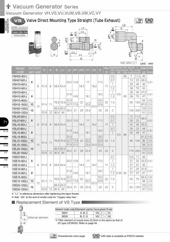
TOR VS Valve Direct Mounting Type Straight (Tube Exhaust) CAD
-2D & 3D-Chart
P.60
V
P
E
øP
1
øP
2
øD
BL1
A
R
CL2
VS□20-□□
Silencer element
AB
C
D
■ Replacement Element of VS TypeElement model code
SE01SE02
Vacuum generator VS modelVS□□ -□01VS□□ -□02
Element partsA, B, CB, C, D
※ Filter element of nozzle bore ø2.0mm is the same as that of VC type (VCSE20). Refer to page 94.
Unit:mm
Model code
Tube O.D.øD1
Tube O.D.øD2
R A B L1 L2 øP1 øP2 C1 C2 EHex.H
Nozzle bore(mm)
Operating pressure
(MPa)
Final vacuum
(-kPa)
Suction flow
(l/min(ANR))
Air consumption(l/min(ANR))
Weight(g)
CAD
file nameVSH05-601J
68 R1/8 8 58.4 54.4
20.2 12.618.4
1718.2
17.217
0.5
0.5
90 7 11.5 46
VS_-601JVSH07-601J 0.7
93
13 23 46.5
VSH10-601J 1 28 46 46
VSH12-601J 1.2 38 70 45
VSH10-801J8
21.614.6 18.1
18.21 28 46 47.5
VS_-801JVSH12-801J 1.2 38 70 47
VSH15-802J
12R1/4 11
76.9 70.922.4
2223.3
19.222 1.5 63 100
94 VS_15-802J
VSH15-1002J 10 24.7 17.8 20.2 20.8 97.5 VS_15-1002J
VSH20-1202J12
89.4 83.335.2 21 28 23.4 25 24 2 104 200
133 VS_20-1202J
VSH20-1203J R3/8 12 90.4 84 141 VS_20-1203J
VSL05-601J6
8 R1/8 8 58.4 54.420.2 12.6
18.417
18.217.2
17
0.5
0.5 66
12 11.546.5
VS_-601JVSL07-601J 0.7 26 23
VSL10-601J 1 42 46 45.5
VSL07-801J8
21.614.6 18.1
18.20.7 26 23 48
VS_-801JVSL10-801J 1 42 46 47
VSL15-802J
12R1/4 11
76.9 70.922.4
2223.3
19.222 1.5 95 100
91.5 VS_15-802J
VSL15-1002J 10 24.7 17.8 20.2 20.8 96 VS_15-1002J
VSL15-1202J12
27.4 21.2 23.4 22.5 99 VSL15-1202J
VSL20-1202J 89.4 83.335.2 21 28 23.4 25 24 2 174 200
133 VS_20-1202J
VSL20-1203J R3/8 12 90.4 84 141 VS_20-1203J
VSE07-601J6
8 R1/8 8 58.4 54.420.2 12.6
18.417
18.217.2
17
0.7
0.35 92
10.5 17 46VS_-601JVSE10-601J 1 21 34 44.5
VSE12-601J 1.2 27 47 46
VSE10-801J8
21.614.6 18.1
18.21 21 34 47.5
VS_-801JVSE12-801J 1.2 27 47 47
VSE15-802J
12R1/4 11
76.9 70.922.4
2223.3
19.222 1.5 42 70
94.5 VS_15-802J
VSE15-1002J 10 24.7 17.8 20.2 20.8 98 VS_15-1002J
VSE20-1202J12
89.4 83.335.2 21 28 23.4 25 24 2 82 150
133 VS_20-1202J
VSE20-1203J R3/8 12 90.4 84 141 VS_20-1203J
※ “L1” is reference dimension after tightening the taper thread.※ Add “-S3” at the end of model code for “Copper alloy free” .
CAD-2D & 3D- CAD data is available at PISCO website.Characteristic chart pageChart
P.000
compliantCopper alloy free
Selectable
R
øD1
øP1
øP2
øD2
C1
EL1H
B
AC2
L2
V
P
EX
72
VN
VZ
VQ
VX
VJ
VK
VG
VM · VC
VB
VU
VH · VS
VY
VUM
VRL
VAC
UU
M
GEN
ERA
TOR
EXTERNAL VACUUM CONTROLLER
VAC
UU
MPA
DVACUUM
ACCESSORIES
ø13
øD
11.8
9.8
9.87.8 CL
L
BB
A AHex. 12
R R
Metric thread typeø6mmRelease ring
ø4mmRelease ring
VP
EXH
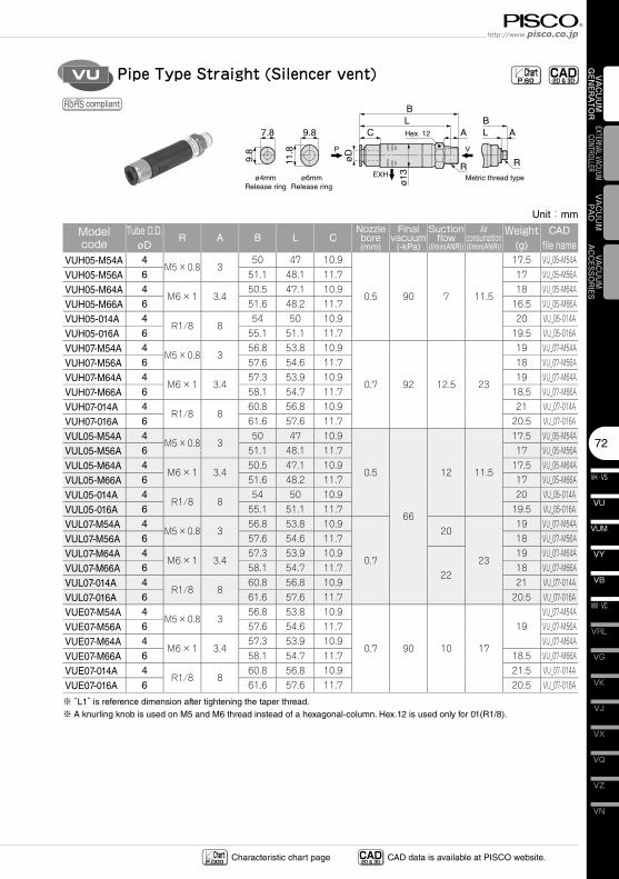
Pipe Type Straight (Silencer vent)VU CAD-2D & 3D- Chart
P.60
Unit:mm
Model code
Tube O.D.øD
R A B L CNozzle bore(mm)
Final vacuum
(-kPa)
Suction flow
(l/min(ANR))
Air consumption(l/min(ANR))
Weight(g)
CAD
file nameVUH05-M54A 4
M5×0.8 350 47 10.9
0.5 90 7 11.5
17.5 VU_05-M54A
VUH05-M56A 6 51.1 48.1 11.7 17 VU_05-M56A
VUH05-M64A 4M6×1 3.4
50.5 47.1 10.9 18 VU_05-M64A
VUH05-M66A 6 51.6 48.2 11.7 16.5 VU_05-M66A
VUH05-014A 4R1/8 8
54 50 10.9 20 VU_05-014A
VUH05-016A 6 55.1 51.1 11.7 19.5 VU_05-016A
VUH07-M54A 4M5×0.8 3
56.8 53.8 10.9
0.7 92 12.5 23
19 VU_07-M54A
VUH07-M56A 6 57.6 54.6 11.7 18 VU_07-M56A
VUH07-M64A 4M6×1 3.4
57.3 53.9 10.9 19 VU_07-M64A
VUH07-M66A 6 58.1 54.7 11.7 18.5 VU_07-M66A
VUH07-014A 4R1/8 8
60.8 56.8 10.9 21 VU_07-014A
VUH07-016A 6 61.6 57.6 11.7 20.5 VU_07-016A
VUL05-M54A 4M5×0.8 3
50 47 10.9
0.5
66
12 11.5
17.5 VU_05-M54A
VUL05-M56A 6 51.1 48.1 11.7 17 VU_05-M56A
VUL05-M64A 4M6×1 3.4
50.5 47.1 10.9 17.5 VU_05-M64A
VUL05-M66A 6 51.6 48.2 11.7 17 VU_05-M66A
VUL05-014A 4R1/8 8
54 50 10.9 20 VU_05-014A
VUL05-016A 6 55.1 51.1 11.7 19.5 VU_05-016A
VUL07-M54A 4M5×0.8 3
56.8 53.8 10.9
0.7
20
23
19 VU_07-M54A
VUL07-M56A 6 57.6 54.6 11.7 18 VU_07-M56A
VUL07-M64A 4M6×1 3.4
57.3 53.9 10.9
22
19 VU_07-M64A
VUL07-M66A 6 58.1 54.7 11.7 18 VU_07-M66A
VUL07-014A 4R1/8 8
60.8 56.8 10.9 21 VU_07-014A
VUL07-016A 6 61.6 57.6 11.7 20.5 VU_07-016A
VUE07-M54A 4M5×0.8 3
56.8 53.8 10.9
0.7 90 10 17
19VU_07-M54A
VUE07-M56A 6 57.6 54.6 11.7 VU_07-M56A
VUE07-M64A 4M6×1 3.4
57.3 53.9 10.9 VU_07-M64A
VUE07-M66A 6 58.1 54.7 11.7 18.5 VU_07-M66A
VUE07-014A 4R1/8 8
60.8 56.8 10.9 21.5 VU_07-014A
VUE07-016A 6 61.6 57.6 11.7 20.5 VU_07-016A
※ “L1” is reference dimension after tightening the taper thread.※ A knurling knob is used on M5 and M6 thread instead of a hexagonal-column. Hex.12 is used only for 01(R1/8).
CAD-2D & 3D- CAD data is available at PISCO website.Characteristic chart page Chart
P.000
compliant
Vacuum Generator SeriesVacuum Generator VH,VS,VU,VUM,VB,VM,VC,VY
VH · VS
73
VU
VB
VM · VC
VY
VUM
VAC
UU
M
GEN
ERA
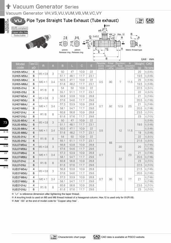
TOR Pipe Type Straight Tube Exhaust (Tube exhaust)VU
ø11ø6
C 15 AE
LB
8.5
ø13
øD 11.6
20.5
VP
EXH
R2-ø3.2
Hex. 12
LB
A
R
Metric thread type
11.8
9.8
9.87.8
ø6mmRelease ring
ø4mmRelease ring
CAD-2D & 3D- Chart
P.60
Unit:mm
Model code
Tube O.D.øD
R A B L C ENozzle bore(mm)
Final vacuum
(-kPa)
Suction flow
(l/min(ANR))
Air consumption(l/min(ANR))
Weight(g)
CAD
file nameVUH05-M54J 4
M5×0.8 350 47 10.9 22
0.5 90 7 11.5
20 VU_05-M54J
VUH05-M56J 6 51.1 48.1 11.7 23.1 19.5 VU_05-M56J
VUH05-M64J 4M6×1 3.4
50.5 47.1 10.9 22 20 VU_05-M64J
VUH05-M66J 6 51.6 48.2 11.7 23.1 19.5 VU_05-M66J
VUH05-014J 4R1/8 8
54 50 10.9 22 22.5 VU_05-014J
VUH05-016J 6 55.1 51.1 11.7 23.1 22 VU_05-016J
VUH07-M54J 4M5×0.8 3
56.8 53.8 10.9 28.8
0.7 92 12.5 23
21 VU_07-M54J
VUH07-M56J 6 57.6 54.6 11.7 29.6 20.5 VU_07-M56J
VUH07-M64J 4M6×1 3.4
57.3 53.9 10.9 28.8 21 VU_07-M64J
VUH07-M66J 6 58.1 54.7 11.7 29.6 20.5 VU_07-M66J
VUH07-014J 4R1/8 8
60.8 56.8 10.9 28.8 23.5 VU_07-014J
VUH07-016J 6 61.6 57.6 11.7 29.6 23 VU_07-016J
VUL05-M54J 4M5×0.8 3
50 47 10.9 22
0.5
66
12 11.5
19.5VU_05-M54J
VUL05-M56J 6 51.1 48.1 11.7 23.1 VU_05-M56J
VUL05-M64J 4M6×1 3.4
50.5 47.1 10.9 22 VU_05-M64J
VUL05-M66J 6 51.6 48.2 11.7 23.1 19 VU_05-M66J
VUL05-014J 4R1/8 8
54 50 10.9 22 22 VU_05-014J
VUL05-016J 6 55.1 51.1 11.7 23.1 21.5 VU_05-016J
VUL07-M54J 4M5×0.8 3
56.8 53.8 10.9 28.8
0.7
20
23
20VU_07-M54J
VUL07-M56J 6 57.6 54.6 11.7 29.6 VU_07-M56J
VUL07-M64J 4M6×1 3.4
57.3 53.9 10.9 28.8
22
21 VU_07-M64J
VUL07-M66J 6 58.1 54.7 11.7 29.6 20.5 VU_07-M66J
VUL07-014J 4R1/8 8
60.8 56.8 10.9 28.8 23 VU_07-014J
VUL07-016J 6 61.6 57.6 11.7 29.6 22.5 VU_07-016J
VUE07-M54J 4M5×0.8 3
56.8 53.8 10.9 28.8
0.7 90 10 17
21.5 VU_07-M54J
VUE07-M56J 6 57.6 54.6 11.7 29.6 20.5 VU_07-M56J
VUE07-M64J 4M6×1 3.4
57.3 53.9 10.9 28.821
VU_07-M64J
VUE07-M66J 6 58.1 54.7 11.7 29.6 VU_07-M66J
VUE07-014J 4R1/8 8
60.8 56.8 10.9 28.8 23.5 VU_07-014J
VUE07-016J 6 61.6 57.6 11.7 29.6 23 VU_07-016J
※ “L1” is reference dimension after tightening the taper thread.※ A knurling knob is used on M5 and M6 thread instead of a hexagonal-column. Hex.12 is used only for 01(R1/8).※ Add “-S3” at the end of model code for “Copper alloy free” .
CAD-2D & 3D- CAD data is available at PISCO website.Characteristic chart page Chart
P.000
compliantCopper alloy free
Selectable
74
VN
VZ
VQ
VX
VJ
VK
VG
VM · VC
VB
VU
VH · VS
VY
VUM
VRL
VAC
UU
M
GEN
ERA
TOR
EXTERNAL VACUUM CONTROLLER
VAC
UU
MPA
DVACUUM
ACCESSORIES
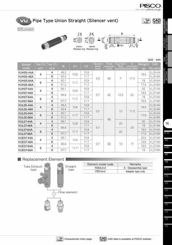
Pipe Type Union Straight (Silencer vent)VU
B
C2 C1
ø13
øD
2
øD
1
VP
EXH
11.8
9.8
9.87.8
ø6mmRelease ring
ø4mmRelease ring
■ Replacement ElementTube Exhaust
typeStraight
type
Filter element
CAD-2D & 3D- Chart
P.60
Element model codeFEE8.2×2FEE10×2
RemarksA:Disassembly type
Adapter type only
Unit:mm
Model code
Tube O.D.øD1
Tube O.D.øD2
B C1 C2Nozzle bore(mm)
Final vacuum
(-kPa)
Suction flow
(l/min(ANR))
Air consumption(l/min(ANR))
Weight(g)
CAD
file nameVUH05-44A
44 49.3
10.910.9
0.5 90 7 11.518.5
VU_05-44A
VUH05-46A 6 50.4 11.7 VU_05-46A
VUH05-64A6
4 50.111.7
10.9 18 VU_05-64A
VUH05-66A 6 51.2 11.7 17.5 VU_05-66A
VUH07-44A4
4 56.110.9
10.9
0.7 92 12.5 23
20 VU_07-44A
VUH07-46A 656.9
11.7 19.5 VU_07-46A
VUH07-64A6
411.7
10.9 19 VU_07-64A
VUH07-66A 6 57.7 11.7 18.5 VU_07-66A
VUL05-44A4
4 49.310.9
10.9
0.5
66
12 11.518.5
VU_05-44A
VUL05-46A 6 50.4 11.7 VU_05-46A
VUL05-64A6
4 50.111.7
10.917.5
VU_05-64A
VUL05-66A 6 51.2 11.7 VU_05-66A
VUL07-44A4
4 56.110.9
10.9
0.720
23
20 VU_07-44A
VUL07-46A 656.9
11.7 19 VU_07-46A
VUL07-64A6
411.7
10.922
18.5 VU_07-64A
VUL07-66A 6 57.7 11.7 17.5 VU_07-66A
VUE07-44A4
4 56.110.9
10.9
0.7 90 10 17
20.5 VU_07-44A
VUE07-46A 656.9
11.7 19.5 VU_07-46A
VUE07-64A6
411.7
10.9 18.5 VU_07-64A
VUE07-66A 6 57.7 11.7 19 VU_07-66A
CAD-2D & 3D- CAD data is available at PISCO website.Characteristic chart page Chart
P.000
compliant
Vacuum Generator SeriesVacuum Generator VH,VS,VU,VUM,VB,VM,VC,VY
VH · VS
75
VU
VB
VM · VC
VY
VUM
VAC
UU
M
GEN
ERA
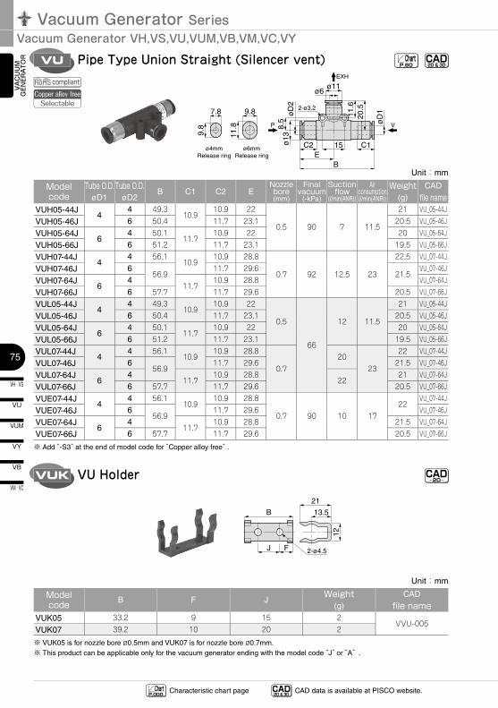
TOR Pipe Type Union Straight (Silencer vent)VU
ø11ø6
C2 15 C1E
B
8.5
ø13
øD
2
11.6
20.5
øD
12-ø3.2
P V
EXH
11.8
9.8
9.87.8
ø6mmRelease ring
ø4mmRelease ring
VU HolderVUK CAD-2D-
12
2-ø4.5
21
13.5
FJ
B
CAD-2D & 3D- Chart
P.60
Unit:mm
Model code
Tube O.D.øD1
Tube O.D.øD2
B C1 C2 ENozzle bore(mm)
Final vacuum
(-kPa)
Suction flow
(l/min(ANR))
Air consumption(l/min(ANR))
Weight(g)
CAD
file nameVUH05-44J
44 49.3
10.910.9 22
0.5 90 7 11.5
21 VU_05-44J
VUH05-46J 6 50.4 11.7 23.1 20.5 VU_05-46J
VUH05-64J6
4 50.111.7
10.9 22 20 VU_05-64J
VUH05-66J 6 51.2 11.7 23.1 19.5 VU_05-66J
VUH07-44J4
4 56.110.9
10.9 28.8
0.7 92 12.5 23
22.5 VU_07-44J
VUH07-46J 656.9
11.7 29.621.5
VU_07-46J
VUH07-64J6
411.7
10.9 28.8 VU_07-64J
VUH07-66J 6 57.7 11.7 29.6 20.5 VU_07-66J
VUL05-44J4
4 49.310.9
10.9 22
0.5
66
12 11.5
21 VU_05-44J
VUL05-46J 6 50.4 11.7 23.1 20.5 VU_05-46J
VUL05-64J6
4 50.111.7
10.9 22 20 VU_05-64J
VUL05-66J 6 51.2 11.7 23.1 19.5 VU_05-66J
VUL07-44J4
4 56.110.9
10.9 28.8
0.720
23
22 VU_07-44J
VUL07-46J 656.9
11.7 29.6 21.5 VU_07-46J
VUL07-64J6
411.7
10.9 28.822
21 VU_07-64J
VUL07-66J 6 57.7 11.7 29.6 20.5 VU_07-66J
VUE07-44J4
4 56.110.9
10.9 28.8
0.7 90 10 1722
VU_07-44J
VUE07-46J 656.9
11.7 29.6 VU_07-46J
VUE07-64J6
411.7
10.9 28.8 21.5 VU_07-64J
VUE07-66J 6 57.7 11.7 29.6 20.5 VU_07-66J
※ Add “-S3” at the end of model code for “Copper alloy free” .
Unit:mm
Model code B F J
Weight(g)
CAD
file nameVUK05 33.2 9 15 2
VVU-005VUK07 39.2 10 20 2
※ VUK05 is for nozzle bore ø0.5mm and VUK07 is for nozzle bore ø0.7mm.※ This product can be applicable only for the vacuum generator ending with the model code “J” or “A” .
CAD-2D & 3D- CAD data is available at PISCO website.Characteristic chart page Chart
P.000
compliantCopper alloy free
Selectable
76
VN
VZ
VQ
VX
VJ
VK
VG
VM · VC
VB
VU
VH · VS
VY
VUM
VRL
VAC
UU
M
GEN
ERA
TOR
EXTERNAL VACUUM CONTROLLER
VAC
UU
MPA
DVACUUM
ACCESSORIES
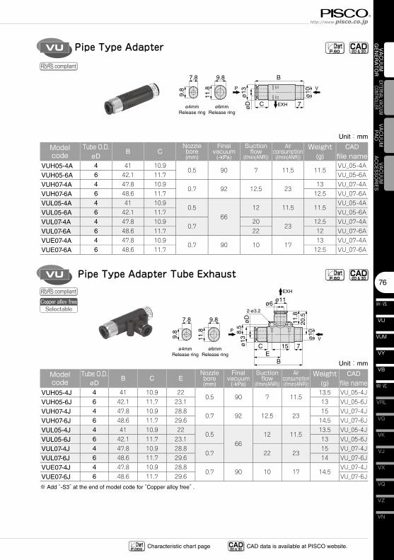
Pipe Type AdapterVU
B
C 7
ø13
øD
ø10
11.8
9.8
9.87.8
ø6mmRelease ring
ø4mmRelease ring
VP
EXH
Pipe Type Adapter Tube ExhaustVU
ø6ø11
C 15 7E
B
8.5
ø13
øD
11.8
20.5
ø10
V
P
EXH
2-ø3.2
11.8
9.8
9.87.8
ø6mmRelease ring
ø4mmRelease ring
CAD-2D & 3D- Chart
P.60
CAD-2D & 3D- Chart
P.60
Unit:mm
Model code
Tube O.D.øD
B CNozzle bore(mm)
Final vacuum
(-kPa)
Suction flow
(l/min(ANR))
Air consumption(l/min(ANR))
Weight(g)
CAD
file nameVUH05-4A 4 41 10.9
0.5 90 7 11.5 11.5VU_05-4A
VUH05-6A 6 42.1 11.7 VU_05-6A
VUH07-4A 4 47.8 10.90.7 92 12.5 23
13 VU_07-4A
VUH07-6A 6 48.6 11.7 12.5 VU_07-6A
VUL05-4A 4 41 10.90.5
6612 11.5 11.5
VU_05-4A
VUL05-6A 6 42.1 11.7 VU_05-6A
VUL07-4A 4 47.8 10.90.7
2023
12.5 VU_07-4A
VUL07-6A 6 48.6 11.7 22 12 VU_07-6A
VUE07-4A 4 47.8 10.90.7 90 10 17
13 VU_07-4A
VUE07-6A 6 48.6 11.7 12.5 VU_07-6A
Unit:mm
Model code
Tube O.D.øD
B C ENozzle bore(mm)
Final vacuum
(-kPa)
Suction flow
(l/min(ANR))
Air consumption(l/min(ANR))
Weight(g)
CAD
file nameVUH05-4J 4 41 10.9 22
0.5 90 7 11.513.5 VU_05-4J
VUH05-6J 6 42.1 11.7 23.1 13 VU_05-6J
VUH07-4J 4 47.8 10.9 28.80.7 92 12.5 23
15 VU_07-4J
VUH07-6J 6 48.6 11.7 29.6 14.5 VU_07-6J
VUL05-4J 4 41 10.9 220.5
6612 11.5
13.5 VU_05-4J
VUL05-6J 6 42.1 11.7 23.1 13 VU_05-6J
VUL07-4J 4 47.8 10.9 28.80.7 22 23
15 VU_07-4J
VUL07-6J 6 48.6 11.7 29.6 14 VU_07-6J
VUE07-4J 4 47.8 10.9 28.80.7 90 10 17 14.5
VU_07-4J
VUE07-6J 6 48.6 11.7 29.6 VU_07-6J
※ Add “-S3” at the end of model code for “Copper alloy free” .
CAD-2D & 3D- CAD data is available at PISCO website.Characteristic chart page Chart
P.000
compliant
compliantCopper alloy free
Selectable
Vacuum Generator SeriesVacuum Generator VH,VS,VU,VUM,VB,VM,VC,VY
VH · VS
77
VU
VB
VM · VC
VY
VUM
VAC
UU
M
GEN
ERA
TOR
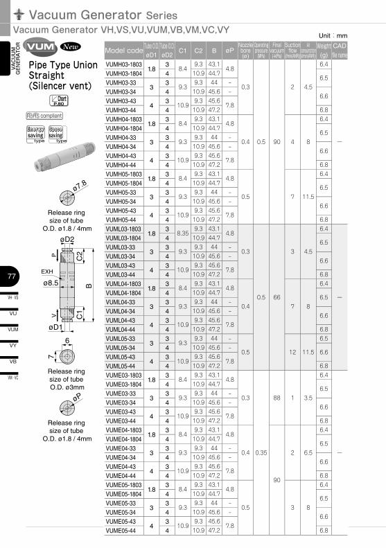
Pipe Type Union Straight (Silencer vent)
VUM
ChartP.80
compliant
6
C1
VP
EXH
C2
B
øD2
øD1
ø8.5
øP
7
Release ring size of tube
O.D. ø1.8 / 4mm
ø7.8
Release ring size of tube
O.D. ø1.8 / 4mm
Release ring size of tube O.D. ø3mm
Energysaving
type
Spacesaving
type
Unit:mm
Model code Tube O.D.øD1
Tube O.D.øD2
C1 C2 B øPNozzle bore(ø)
Operating pressure
(MPa)
Final vacuum
(-kPa)
Suction flow
(l/min(ANR))
Air consumption(l/min(ANR))
Weight(g)
CAD
file nameVUMH03-1803
1.83
8.49.3 43.1
4.8
0.3
0.5 90
2 4.5
6.4
ー
VUMH03-1804 4 10.9 44.76.5
VUMH03-333
39.3
9.3 44 –
VUMH03-34 4 10.9 45.6 –6.6
VUMH03-434
310.9
9.3 45.67.8
VUMH03-44 4 10.9 47.2 6.8
VUMH04-18031.8
38.4
9.3 43.14.8
0.4 4 8
6.4
VUMH04-1804 4 10.9 44.76.5
VUMH04-333
39.3
9.3 44 –
VUMH04-34 4 10.9 45.6 –6.6
VUMH04-434
310.9
9.3 45.67.8
VUMH04-44 4 10.9 47.2 6.8
VUMH05-18031.8
38.4
9.3 43.14.8
0.5 7 11.5
6.4
VUMH05-1804 4 10.9 44.76.5
VUMH05-333
39.3
9.3 44 –
VUMH05-34 4 10.9 45.6 –6.6
VUMH05-434
310.9
9.3 45.67.8
VUMH05-44 4 10.9 47.2 6.8
VUML03-18031.8
38.35
9.3 43.14.8
0.3
0.5 66
3 4.5
6.4
ー
VUML03-1804 4 10.9 44.76.5
VUML03-333
39.3
9.3 44 –
VUML03-34 4 10.9 45.6 –6.6
VUML03-434
310.9
9.3 45.67.8
VUML03-44 4 10.9 47.2 6.8
VUML04-18031.8
38.4
9.3 43.14.8
0.4 7 8
6.4
VUML04-1804 4 10.9 44.76.5
VUML04-333
39.3
9.3 44 –
VUML04-34 4 10.9 45.6 –6.6
VUML04-434
310.9
9.3 45.67.8
VUML04-44 4 10.9 47.2 6.8
VUML05-333
39.3
9.3 44 –
0.5 12 11.5
6.5
VUML05-34 4 10.9 45.6 –6.6
VUML05-434
310.9
9.3 45.67.8
VUML05-44 4 10.9 47.2 6.8
VUME03-18031.8
38.4
9.3 43.14.8
0.3
0.35
88 1 3.5
6.4
ー
VUME03-1804 4 10.9 44.76.5
VUME03-333
39.3
9.3 44 –
VUME03-34 4 10.9 45.6 –6.6
VUME03-434
310.9
9.3 45.67.8
VUME03-44 4 10.9 47.2 6.8
VUME04-18031.8
38.4
9.3 43.14.8
0.4
90
2 6.5
6.4
VUME04-1804 4 10.9 44.76.5
VUME04-333
39.3
9.3 44 –
VUME04-34 4 10.9 45.6 –6.6
VUME04-434
310.9
9.3 45.67.8
VUME04-44 4 10.9 47.2 6.8
VUME05-18031.8
38.4
9.3 43.14.8
0.5 3 8
6.4
VUME05-1804 4 10.9 44.76.5
VUME05-333
39.3
9.3 44 –
VUME05-34 4 10.9 45.6 –6.6
VUME05-434
310.9
9.3 45.67.8
VUME05-44 4 10.9 47.2 6.8
78
VN
VZ
VQ
VX
VJ
VK
VG
VM · VC
VB
VU
VH · VS
VY
VUM
VRL
VAC
UU
M
GEN
ERA
TOR
EXTERNAL VACUUM CONTROLLER
VAC
UU
MPA
DVACUUM
ACCESSORIES
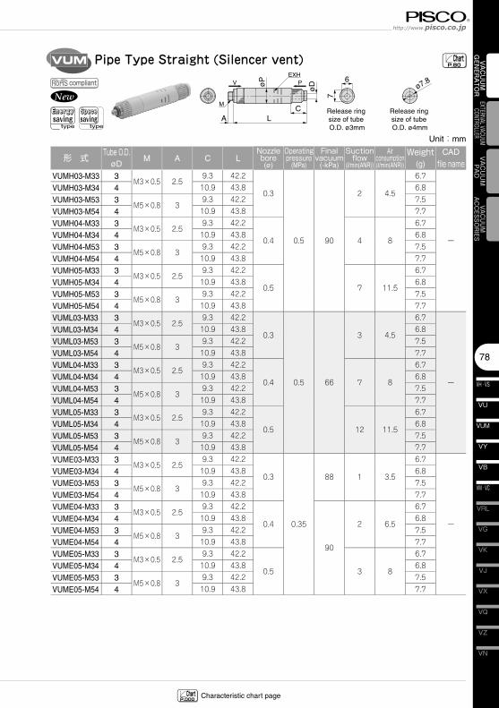
Pipe Type Straight (Silencer vent)VUM
CLA
øP
øD
EXH
M
V P 6ø7.8
7
Release ring size of tube O.D. ø4mm
Release ring size of tube O.D. ø3mm
ChartP.80
Characteristic chart page ChartP.000
Energysaving
type
Spacesaving
type
compliant
Unit:mm
形 式 Tube O.D.øD
M A C LNozzle bore(ø)
Operating pressure
(MPa)
Final vacuum
(-kPa)
Suction flow
(l/min(ANR))
Air consumption(l/min(ANR))
Weight(g)
CAD
file nameVUMH03-M33 3
M3×0.5 2.59.3 42.2
0.3
0.5 90
2 4.5
6.7
ー
VUMH03-M34 4 10.9 43.8 6.8
VUMH03-M53 3M5×0.8 3
9.3 42.2 7.5
VUMH03-M54 4 10.9 43.8 7.7
VUMH04-M33 3M3×0.5 2.5
9.3 42.2
0.4 4 8
6.7
VUMH04-M34 4 10.9 43.8 6.8
VUMH04-M53 3M5×0.8 3
9.3 42.2 7.5
VUMH04-M54 4 10.9 43.8 7.7
VUMH05-M33 3M3×0.5 2.5
9.3 42.2
0.5 7 11.5
6.7
VUMH05-M34 4 10.9 43.8 6.8
VUMH05-M53 3M5×0.8 3
9.3 42.2 7.5
VUMH05-M54 4 10.9 43.8 7.7
VUML03-M33 3M3×0.5 2.5
9.3 42.2
0.3
0.5 66
3 4.5
6.7
ー
VUML03-M34 4 10.9 43.8 6.8
VUML03-M53 3M5×0.8 3
9.3 42.2 7.5
VUML03-M54 4 10.9 43.8 7.7
VUML04-M33 3M3×0.5 2.5
9.3 42.2
0.4 7 8
6.7
VUML04-M34 4 10.9 43.8 6.8
VUML04-M53 3M5×0.8 3
9.3 42.2 7.5
VUML04-M54 4 10.9 43.8 7.7
VUML05-M33 3M3×0.5 2.5
9.3 42.2
0.5 12 11.5
6.7
VUML05-M34 4 10.9 43.8 6.8
VUML05-M53 3M5×0.8 3
9.3 42.2 7.5
VUML05-M54 4 10.9 43.8 7.7
VUME03-M33 3M3×0.5 2.5
9.3 42.2
0.3
0.35
88 1 3.5
6.7
ー
VUME03-M34 4 10.9 43.8 6.8
VUME03-M53 3M5×0.8 3
9.3 42.2 7.5
VUME03-M54 4 10.9 43.8 7.7
VUME04-M33 3M3×0.5 2.5
9.3 42.2
0.4
90
2 6.5
6.7
VUME04-M34 4 10.9 43.8 6.8
VUME04-M53 3M5×0.8 3
9.3 42.2 7.5
VUME04-M54 4 10.9 43.8 7.7
VUME05-M33 3M3×0.5 2.5
9.3 42.2
0.5 3 8
6.7
VUME05-M34 4 10.9 43.8 6.8
VUME05-M53 3M5×0.8 3
9.3 42.2 7.5
VUME05-M54 4 10.9 43.8 7.7
Vacuum Generator SeriesVacuum Generator VH,VS,VU,VUM,VB,VM,VC,VY
VH · VS
79
VU
VB
VM · VC
VY
VUM
VAC
UU
M
GEN
ERA
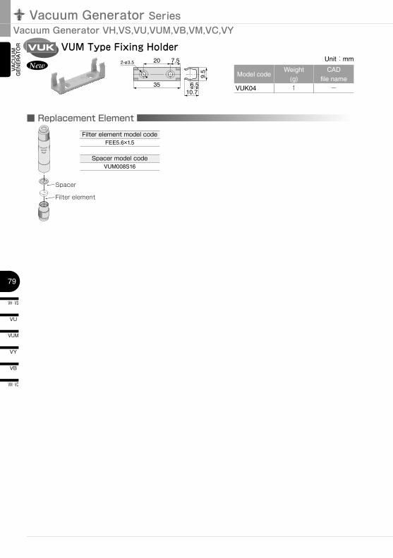
TOR VUM Type Fixing HolderVUK
202-ø3.5 7.5
3510.7
6.5
9.5
New
■ Replacement ElementFilter element model code
FEE5.6×1.5
Spacer model codeVUM008S16
Unit:mm
Model codeWeight
(g)CAD
file nameVUK04 1 ー
Spacer
Filter element
80
VN
VZ
VQ
VX
VJ
VK
VG
VM · VC
VB
VU
VH · VS
VY
VUM
VRL
VAC
UU
M
GEN
ERA
TOR
EXTERNAL VACUUM CONTROLLER
VAC
UU
MPA
DVACUUM
ACCESSORIES
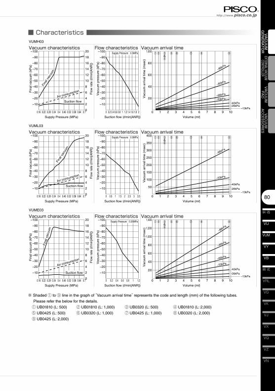
■ Characteristics
0.16 0.22 0.28 0.34 0.4 0.46 0.52 0.58 0.64 0.7 0 0.2 0.4 0.6 0.8 1 1.2 1.4 1.6 1.8 2
–10
–20
–30
–40
–50
–60
–70
–80
–90
–100
–10
–20
–30
–40
–50
–60
–70
–80
–90
–100
Supply Pressure (MPa) Suction flow (l/min[ANR])
Fin
al v
acuu
m (
kPa)
Vac
uum
pre
ssur
e (k
Pa)
Flo
w r
ate
(l/m
in[A
NR
])
VUMH03
Vacuum characteristics Flow characteristics
0
2
4
6
8
10
12
14
16
18
20 Supply Pressure:0.5MPa
Fina
l vac
uum
Air consumption
Suction flow
0 1 2 3 4 5 6 7 8 9 10–13kPa
Volume (ml)
Vacuum arrival time
Vac
uum
arr
ival
tim
e (m
sec)
200
400
600
800
1,000
–86kPa
–80kPa
–66kPa
–53kPa
–40kPa–26kPa
–86kPa
–80kPa
–66kPa
–53kPa
–40kPa–26kPa
①② ③&④
⑤ ⑥ ⑦ ⑧ ⑨
0.16 0.22 0.28 0.34 0.4 0.46 0.52 0.58 0.64 0.7 0 0.5 1 1.5 2 2.5 3 3.5
–10
–20
–30
–40
–50
–60
–70
–80
–90
–100
–10
–20
–30
–40
–50
–60
–70
–80
–90
–100
Supply Pressure (MPa) Suction flow (l/min[ANR])
Fin
al v
acuu
m (
kPa)
Vac
uum
pre
ssur
e (k
Pa)
Flo
w r
ate
(l/m
in[A
NR
])
VUML03
Vacuum characteristics Flow characteristics
0
2
4
6
8
10
12
14
16
18
20 Supply Pressure:0.5MPa
Fina
l vac
uum
Air consumption
Suction flow
0 1 2 3 4 5 6 7 8 9 10–13kPa
Volume (ml)
Vacuum arrival time
Vac
uum
arr
ival
tim
e (m
sec)
50
100
150
200
250
300
350
400
–66kPa
–53kPa
–40kPa
–26kPa
–66kPa
–53kPa
–40kPa
–26kPa
①② ③&④
⑤ ⑥ ⑦ ⑧ ⑨
0.16 0.22 0.28 0.34 0.4 0.46 0.52 0.58 0.64 0.7 0 0.2
–10
–20
–30
–40
–50
–60
–70
–80
–90
–100
–10
–20
–30
–40
–50
–60
–70
–80
–90
–100
Supply Pressure (MPa) Suction flow (l/min[ANR])
Fin
al v
acuu
m (
kPa)
Vac
uum
pre
ssur
e (k
Pa)
Flo
w r
ate
(l/m
in[A
NR
])
VUME03
Vacuum characteristics Flow characteristics
0
2
4
6
8
10
12
14
16
18
20
0.4 0.6 0.8 1 1.2
Supply Pressure:0.35MPa
Fin
al v
acuu
m
Air consumption
Suction flow
0 1 2 3 4 5 6 7 8 9 10–13kPa
Volume (ml)
Vacuum arrival time
Vac
uum
arr
ival
tim
e (m
sec)
200
400
600
800
1,000
1,200
1,400
–86kPa
–80kPa
–66kPa
–53kPa
–40kPa
–26kPa
–86kPa
–80kPa
–66kPa
–53kPa
–40kPa
–26kPa
①② ③&④
⑤ ⑥ ⑦ ⑧ ⑨
※ Shaded ① to ⑨ line in the graph of “Vacuum arrival time” represents the code and length (mm) of the following tubes.
Please refer the below for the details.
① UB01810 (L: 500) ② UB01810 (L: 1,000) ③ UB0320 (L: 500) ④ UB01810 (L: 2,000)
⑤ UB0425 (L: 500) ⑥ UB0320 (L: 1,000) ⑦ UB0425 (L: 1,000) ⑧ UB0320 (L: 2,000)
⑨ UB0425 (L: 2,000)
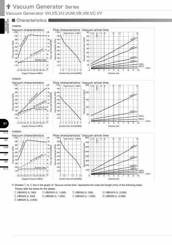
Vacuum Generator SeriesVacuum Generator VH,VS,VU,VUM,VB,VM,VC,VY
VH · VS
81
VU
VB
VM · VC
VY
VUM
VAC
UU
M
GEN
ERA
TOR
0.16 0.22 0.28 0.34 0.4 0.46 0.52 0.58 0.64 0.7 0 0.5
–10
–20
–30
–40
–50
–60
–70
–80
–90
–100
–10
–20
–30
–40
–50
–60
–70
–80
–90
–100
Supply Pressure (MPa) Suction flow (l/min[ANR])
Fin
al v
acuu
m (
kPa)
Vac
uum
pre
ssur
e (k
Pa)
Flo
w r
ate
(l/m
in[A
NR
])
VUMH04
Vacuum characteristics Flow characteristics
0
2
4
6
8
10
12
14
16
18
20
1 1.5 2 2.5 3 3.5
Supply Pressure:0.5MPa
Fina
l vac
uum
Air consumption
Suction flow
0 1 2 3 4 5 6 7 8 9 10–13kPa
Volume (ml)
Vacuum arrival time
Vac
uum
arr
ival
tim
e (m
sec)
50
100
150
200
250
300
350
400
450
–86kPa
–80kPa
–66kPa
–53kPa
–40kPa–26kPa
–86kPa
–80kPa
–66kPa
–53kPa
–40kPa–26kPa
①② ③&④
⑤ ⑥ ⑦ ⑧ ⑨
0.16 0.22 0.28 0.34 0.4 0.46 0.52 0.58 0.64 0.7 0 1 2 3 4 5 6 7
–10
–20
–30
–40
–50
–60
–70
–80
–90
–100
–10
–20
–30
–40
–50
–60
–70
–80
–90
–100
Supply Pressure (MPa) Suction flow (l/min[ANR])
Fin
al v
acuu
m (
kPa)
Vac
uum
pre
ssur
e (k
Pa)
Flo
w r
ate
(l/m
in[A
NR
])
VUML04
Vacuum characteristics Flow characteristics
0
2
4
6
8
10
12
14
16
18
20 Supply Pressure:0.5MPa
Final v
acuu
m
Suction flow
0 1 2 3 4 5 6 7 8 9 10–13kPa
Volume (ml)
Vacuum arrival timeV
acuu
m a
rriv
al ti
me
(mse
c)
50
100
150
200
250
–66kPa
–53kPa
–40kPa
–26kPa
–66kPa
–53kPa
–40kPa
–26kPa
①② ③&④
⑤ ⑥ ⑦ ⑧ ⑨
0.16 0.22 0.28 0.34 0.4 0.46 0.52 0.58 0.64 0.7 0 0.5 1 1.5 2 2.5
–10
–20
–30
–40
–50
–60
–70
–80
–90
–100
–10
–20
–30
–40
–50
–60
–70
–80
–90
–100
Supply Pressure (MPa) Suction flow (l/min[ANR])
Fin
al v
acuu
m (
kPa)
Vac
uum
pre
ssur
e (k
Pa)
Flo
w r
ate
(l/m
in[A
NR
])
VUME04
Vacuum characteristics Flow characteristics
0
2
4
6
8
10
12
14
16
18
20 Supply Pressure:0.35MPa
Fin
al v
acuu
m
Suction flow
0 1 2 3 4 5 6 7 8 9 10–13kPa
Volume (ml)
Vacuum arrival time
Vac
uum
arr
ival
tim
e (m
sec)
100
200
300
400
500
600
700
800
–86kPa
–80kPa
–66kPa
–53kPa
–40kPa–26kPa
–86kPa
–80kPa
–66kPa
–53kPa
–40kPa–26kPa
①② ③&④
⑤ ⑥ ⑦ ⑧ ⑨
Air consumption
Air consumption
■ Characteristics
※ Shaded ① to ⑨ line in the graph of “Vacuum arrival time” represents the code and length (mm) of the following tubes.
Please refer the below for the details.
① UB01810 (L: 500) ② UB01810 (L: 1,000) ③ UB0320 (L: 500) ④ UB01810 (L: 2,000)
⑤ UB0425 (L: 500) ⑥ UB0320 (L: 1,000) ⑦ UB0425 (L: 1,000) ⑧ UB0320 (L: 2,000)
⑨ UB0425 (L: 2,000)
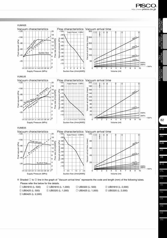
82
VN
VZ
VQ
VX
VJ
VK
VG
VM · VC
VB
VU
VH · VS
VY
VUM
VRL
VAC
UU
M
GEN
ERA
TOR
EXTERNAL VACUUM CONTROLLER
VAC
UU
MPA
DVACUUM
ACCESSORIES
0.16 0.22 0.28 0.34 0.4 0.46 0.52 0.58 0.64 0.7 0 1 2 3 4 5 6
–20
–40
–60
–80
–100
–120
–10
–20
–30
–40
–50
–60
–70
–80
–90
–100
Supply Pressure (MPa) Suction flow (l/min[ANR])
Fin
al v
acuu
m (
kPa)
Vac
uum
pre
ssur
e (k
Pa)
Flo
w r
ate
(l/m
in[A
NR
])
VUMH05
Vacuum characteristics Flow characteristics
0
2
4
6
8
10
12
14
16
18
20 Supply Pressure:0.5MPa
Fina
l vac
uum
Air consu
mption
Suction flow
0.16 0.22 0.28 0.34 0.4 0.46 0.52 0.58 0.64 0.7
–20
–40
–60
–80
–100
–120
Supply Pressure (MPa)
Fin
al v
acuu
m (
kPa)
Flo
w r
ate
(l/m
in[A
NR
])
Vacuum characteristics
0
2
4
6
8
10
12
14
16
18
20
Final vacu
um
Air consu
mption
Suction flow
0.16 0.22 0.28 0.34 0.4 0.46 0.52 0.58 0.64 0.7
–20
–40
–60
–80
–100
–120
Supply Pressure (MPa)
Fin
al v
acuu
m (
kPa)
Flo
w r
ate
(l/m
in[A
NR
])
Vacuum characteristics
0
2
4
6
8
10
12
14
16
18
20
Final vacuum
Air consu
mption
Suction flow
0 1 2 3 4 5 6 7 8 9 10–13kPa
Volume (ml)
Vacuum arrival time
Vac
uum
arr
ival
tim
e (m
sec)
50
100
150
200
250
300
–86kPa
–80kPa
–66kPa
–53kPa
–40kPa–26kPa
–86kPa
–80kPa
–66kPa
–53kPa
–40kPa–26kPa
①② ③&④
⑤ ⑥ ⑦ ⑧ ⑨
0 1 2 3 4 5 6 7 8 9 10
–10
–20
–30
–40
–50
–60
–70
–80
–90
–100
Suction flow (l/min[ANR])
Vac
uum
pre
ssur
e (k
Pa)
VUML05
Flow characteristicsSupply Pressure:0.5MPa
0 1 2 3 4 5 6 7 8 9 10–13kPa
Volume (ml)
Vacuum arrival time
Vac
uum
arr
ival
tim
e (m
sec)
20
40
60
80
100
120
140
160
180
200
–66kPa
–53kPa
–40kPa
–26kPa
–66kPa
–53kPa
–40kPa
–26kPa
①② ③&④
⑤ ⑥ ⑦ ⑧ ⑨
0 0.5 1 1.5 2 2.5
–10
–20
–30
–40
–50
–60
–70
–80
–90
–100
Suction flow (l/min[ANR])
Vac
uum
pre
ssur
e (k
Pa)
VUME05
Flow characteristicsSupply Pressure:0.35MPa
0 1 2 3 4 5 6 7 8 9 10–13kPa
Volume (ml)
Vacuum arrival time
Vac
uum
arr
ival
tim
e (m
sec)
200
400
600
800
1,000
–86kPa
–80kPa
–66kPa
–53kPa–40kPa–26kPa
–86kPa
–80kPa
–66kPa
–53kPa–40kPa–26kPa
①② ③&④
⑤ ⑥ ⑦ ⑧ ⑨
※ Shaded ① to ⑨ line in the graph of “Vacuum arrival time” represents the code and length (mm) of the following tubes.
Please refer the below for the details.
① UB01810 (L: 500) ② UB01810 (L: 1,000) ③ UB0320 (L: 500) ④ UB01810 (L: 2,000)
⑤ UB0425 (L: 500) ⑥ UB0320 (L: 1,000) ⑦ UB0425 (L: 1,000) ⑧ UB0320 (L: 2,000)
⑨ UB0425 (L: 2,000)
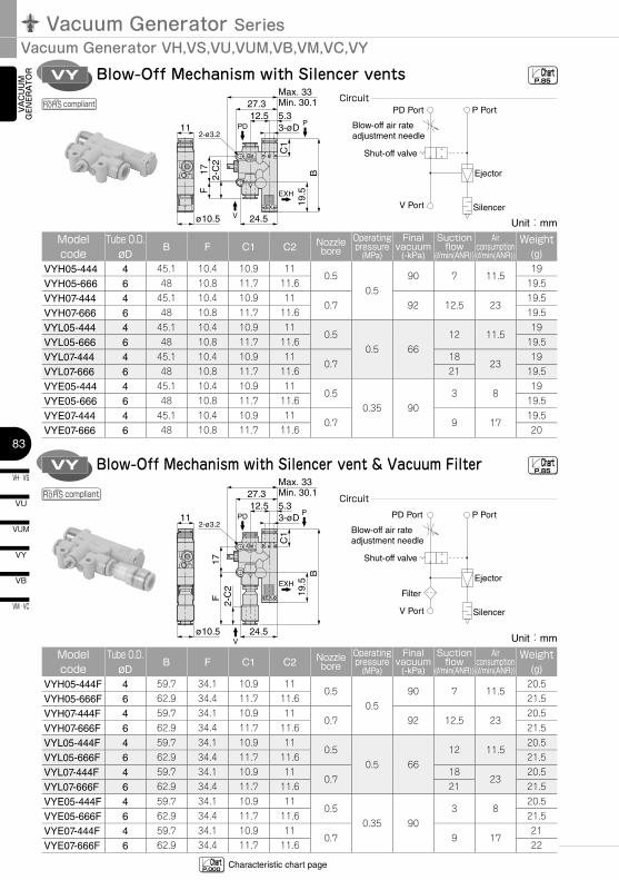
Vacuum Generator SeriesVacuum Generator VH,VS,VU,VUM,VB,VM,VC,VY
VH · VS
83
VU
VB
VM · VC
VY
VUM
VAC
UU
M
GEN
ERA
TOR Blow-Off Mechanism with Silencer ventsVY
Max. 33Min. 30.127.3
12.5 5.33-øD11
ø10.5 24.5
B19
.5
C1
2-C
2F
17
2-ø3.2
V
PPD
EXH
Blow-Off Mechanism with Silencer vent & Vacuum FilterVYMax. 33Min. 30.127.3
12.5 5.33-øD11
ø10.5 24.5
B19
.5
C1
2-C
2F
17
2-ø3.2
V
PPD
EXH
ChartP.85
ChartP.85
Characteristic chart page ChartP.000
compliant
compliant
Unit:mm
Model code
Tube O.D.øD
B F C1 C2 Nozzle bore
Operating pressure
(MPa)
Final vacuum
(-kPa)
Suction flow
(l/min(ANR))
Air consumption(l/min(ANR))
Weight(g)
VYH05-444 4 45.1 10.4 10.9 110.5
0.590 7 11.5
19
VYH05-666 6 48 10.8 11.7 11.6 19.5
VYH07-444 4 45.1 10.4 10.9 110.7 92 12.5 23
19.5
VYH07-666 6 48 10.8 11.7 11.6 19.5
VYL05-444 4 45.1 10.4 10.9 110.5
0.5 6612 11.5
19
VYL05-666 6 48 10.8 11.7 11.6 19.5
VYL07-444 4 45.1 10.4 10.9 110.7
1823
19
VYL07-666 6 48 10.8 11.7 11.6 21 19.5
VYE05-444 4 45.1 10.4 10.9 110.5
0.35 903 8
19
VYE05-666 6 48 10.8 11.7 11.6 19.5
VYE07-444 4 45.1 10.4 10.9 110.7 9 17
19.5
VYE07-666 6 48 10.8 11.7 11.6 20
Unit:mm
Model code
Tube O.D.øD
B F C1 C2 Nozzle bore
Operating pressure
(MPa)
Final vacuum
(-kPa)
Suction flow
(l/min(ANR))
Air consumption(l/min(ANR))
Weight(g)
VYH05-444F 4 59.7 34.1 10.9 110.5
0.590 7 11.5
20.5
VYH05-666F 6 62.9 34.4 11.7 11.6 21.5
VYH07-444F 4 59.7 34.1 10.9 110.7 92 12.5 23
20.5
VYH07-666F 6 62.9 34.4 11.7 11.6 21.5
VYL05-444F 4 59.7 34.1 10.9 110.5
0.5 6612 11.5
20.5
VYL05-666F 6 62.9 34.4 11.7 11.6 21.5
VYL07-444F 4 59.7 34.1 10.9 110.7
1823
20.5
VYL07-666F 6 62.9 34.4 11.7 11.6 21 21.5
VYE05-444F 4 59.7 34.1 10.9 110.5
0.35 903 8
20.5
VYE05-666F 6 62.9 34.4 11.7 11.6 21.5
VYE07-444F 4 59.7 34.1 10.9 110.7 9 17
21
VYE07-666F 6 62.9 34.4 11.7 11.6 22
PD Port P Port
Ejector
Silencer
Blow-off air rate adjustment needle
Shut-off valve
V Port
PD Port P Port
Ejector
Silencer
Blow-off air rate adjustment needle
Shut-off valve
V Port
Filter
Circuit
Circuit
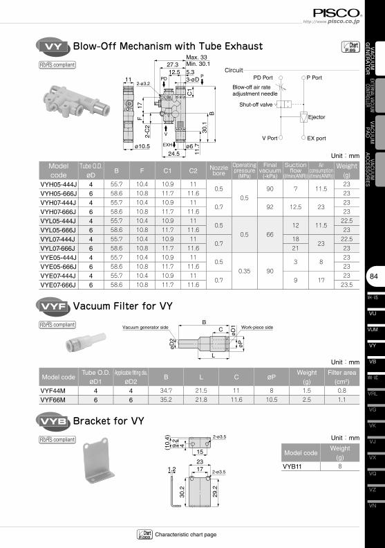
84
VN
VZ
VQ
VX
VJ
VK
VG
VM · VC
VB
VU
VH · VS
VY
VUM
VRL
VAC
UU
M
GEN
ERA
TOR
EXTERNAL VACUUM CONTROLLER
VAC
UU
MPA
DVACUUM
ACCESSORIES
Blow-Off Mechanism with Tube ExhaustVYMax. 33Min. 30.127.3
12.5 5.33-øD11
ø10.5 ø624.5
B30
.111
.7C
1
2-C
2F
17
2-ø3.2
V
PPD
EXH
ChartP.85
Characteristic chart page ChartP.000
Vacuum Filter for VYVYF
BC
L
øD
1ø
P
øD
2
Vacuum generator side Work-piece side
Bracket for VYVYB
15
1.22317
29.2
30.2
(10.
4)9.
24
2-ø3.5
2-ø3.5
compliant
compliant
compliant
Unit:mm
Model code
Tube O.D.øD
B F C1 C2 Nozzle bore
Operating pressure
(MPa)
Final vacuum
(-kPa)
Suction flow
(l/min(ANR))
Air consumption(l/min(ANR))
Weight(g)
VYH05-444J 4 55.7 10.4 10.9 110.5
0.590 7 11.5
23
VYH05-666J 6 58.6 10.8 11.7 11.6 23
VYH07-444J 4 55.7 10.4 10.9 110.7 92 12.5 23
23
VYH07-666J 6 58.6 10.8 11.7 11.6 23
VYL05-444J 4 55.7 10.4 10.9 110.5
0.5 6612 11.5
22.5
VYL05-666J 6 58.6 10.8 11.7 11.6 23
VYL07-444J 4 55.7 10.4 10.9 110.7
1823
22.5
VYL07-666J 6 58.6 10.8 11.7 11.6 21 23
VYE05-444J 4 55.7 10.4 10.9 110.5
0.35 903 8
23
VYE05-666J 6 58.6 10.8 11.7 11.6 23
VYE07-444J 4 55.7 10.4 10.9 110.7 9 17
23
VYE07-666J 6 58.6 10.8 11.7 11.6 23.5
PD Port P Port
Ejector
EX port
Blow-off air rate adjustment needle
Shut-off valve
V Port
Circuit
Unit:mm
Model codeTube O.D.
øD1Applicable fitting dia.
øD2B L C øP
Weight(g)
Filter area(cm2)
VYF44M 4 4 34.7 21.5 11 8 1.5 0.8
VYF66M 6 6 35.2 21.8 11.6 10.5 2.5 1.1
Unit:mm
Model codeWeight
(g)VYB11 8
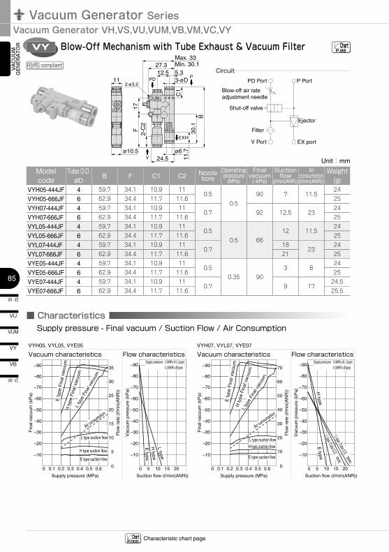
Vacuum Generator SeriesVacuum Generator VH,VS,VU,VUM,VB,VM,VC,VY
VH · VS
85
VU
VB
VM · VC
VY
VUM
VAC
UU
M
GEN
ERA
TOR Blow-Off Mechanism with Tube Exhaust & Vacuum FilterVY
Max. 33Min. 30.127.3
12.5 5.33-øD11
ø10.5 ø624.5
B30
.111
.7C
1
2-C
2F
17
2-ø3.2
V
PPD
EXH
ChartP.85
Characteristic chart page ChartP.000
0 0 5 10 15 20
–10
–20
–30
–40
–50
–60
–70
–80
–90
–10
–20
–30
–40
–50
–60
–70
–80
–90
–10
–20
–30
–40
–50
–60
–70
0.1 0.2 0.3 0.4 0.5 0.6
Supply pressure (MPa) Suction flow (l/min(ANR))
Fin
al v
acuu
m (
kPa)
Vac
uum
pre
ssur
e (k
Pa)
Flo
w r
ate
(l/m
in(A
NR
))
VYH05, VYL05, VYE05
Vacuum characteristics Flow characteristics
0
5
10
15
20
25
30
35
–80
–90
H type
L type
0 0 5 10 15
–10
–20
–30
–40
–50
–60
–70
0.1 0.2 0.3 0.4 0.5 0.6
Supply pressure (MPa) Suction flow (l/min(ANR))
Fin
al v
acuu
m (
kPa)
Vac
uum
pre
ssur
e (k
Pa)
Flo
w r
ate
(l/m
in(A
NR
))
VYH07, VYL07, VYE07
Vacuum characteristics Flow characteristics
0
10
20
30
40
50
60
70
–80
–90
20
H type
E type
L type (Tube O.D.:4mm)L type (Tube O.D.:6mm)
Supply pressure:0.5MPa (H, Ltype)0.35MPa (Etype)
Supply pressure:0.5MPa (H, Ltype)0.35MPa (Etype)
E ty
pe F
inal
vac
uum
H ty
pe F
inal
vac
uum
L ty
pe F
inal
vac
uum
Air consumption
L type suction flow
H type suction flow
E type suction flow
E type
H ty
pe F
inal
vac
uum
E ty
pe F
inal
vac
uum
L ty
pe F
inal
vac
uum
H type suction flow
E type suction flow
Air consumption
L type suction flow
compliant
Unit:mm
Model code
Tube O.D.øD
B F C1 C2 Nozzle bore
Operating pressure
(MPa)
Final vacuum
(-kPa)
Suction flow
(l/min(ANR))
Air consumption(l/min(ANR))
Weight(g)
VYH05-444JF 4 59.7 34.1 10.9 110.5
0.590 7 11.5
24
VYH05-666JF 6 62.9 34.4 11.7 11.6 25
VYH07-444JF 4 59.7 34.1 10.9 110.7 92 12.5 23
24
VYH07-666JF 6 62.9 34.4 11.7 11.6 25
VYL05-444JF 4 59.7 34.1 10.9 110.5
0.5 6612 11.5
24
VYL05-666JF 6 62.9 34.4 11.7 11.6 25
VYL07-444JF 4 59.7 34.1 10.9 110.7
1823
24
VYL07-666JF 6 62.9 34.4 11.7 11.6 21 25
VYE05-444JF 4 59.7 34.1 10.9 110.5
0.35 903 8
24
VYE05-666JF 6 62.9 34.4 11.7 11.6 25
VYE07-444JF 4 59.7 34.1 10.9 110.7 9 17
24.5
VYE07-666JF 6 62.9 34.4 11.7 11.6 25.5
PD Port P Port
Ejector
EX port
Blow-off air rate adjustment needle
Shut-off valve
V Port
Filter
Circuit
■ CharacteristicsSupply pressure - Final vacuum / Suction Flow / Air Consumption
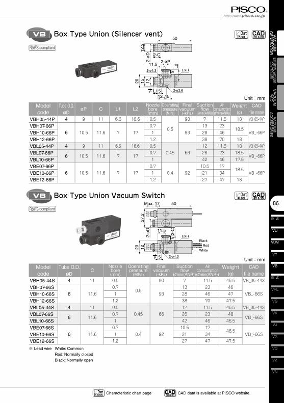
86
VN
VZ
VQ
VX
VJ
VK
VG
VM · VC
VB
VU
VH · VS
VY
VUM
VRL
VAC
UU
M
GEN
ERA
TOR
EXTERNAL VACUUM CONTROLLER
VAC
UU
MPA
DVACUUM
ACCESSORIES
Box Type Union (Silencer vent)
Box Type Union Vacuum Switch
VB
VB
CAD-2D & 3D- Chart
P.60
CAD-2D & 3D- Chart
P.60
Unit:mm
Model code
Tube O.D.øD
øP C L1 L2Nozzle bore(mm)
Operating pressure
(MPa)
Final vacuum
(-kPa)
Suction flow
(l/min(ANR))
Air consumption(l/min(ANR))
Weight(g)
CAD
file nameVBH05-44P 4 9 11 6.6 16.6 0.5
0.5
90 7 11.5 18 VB_05-44P
VBH07-66P6 10.5 11.6 7 17
0.793
13 2318.5
VB_-66PVBH10-66P 1 28 46
VBH12-66P 1.2 38 70 18
VBL05-44P 4 9 11 6.6 16.6 0.50.45 66
12 11.5 18 VB_05-44P
VBL07-66P6 10.5 11.6 7 17
0.7 26 23 18.5VB_-66P
VBL10-66P 1 42 46 17.5
VBE07-66P6 10.5 11.6 7 17
0.70.4 92
10.5 1718.5
VB_-66PVBE10-66P 1 21 34
VBE12-66P 1.2 27 47 18
Unit:mm
Model code
Tube O.D.øD
CNozzle bore(mm)
Operating pressure
(MPa)
Final vacuum
(-kPa)
Suction flow
(l/min(ANR))
Air consumption(l/min(ANR))
Weight(g)
CAD
file nameVBH05-44S 4 11 0.5
0.5
90 7 11.5 46.5 VB_05-44S
VBH07-66S6 11.6
0.793
13 23 46VB_-66SVBH10-66S 1 28 46 47
VBH12-66S 1.2 38 70 47.5
VBL05-44S 4 11 0.50.45 66
12 11.5 46.5 VB_05-44S
VBL07-66S6 11.6
0.7 26 23 48VB_-66S
VBL10-66S 1 42 46 46.5
VBE07-66S6 11.6
0.70.4 92
10.5 1748.5
VB_-66SVBE10-66S 1 21 34
VBE12-66S 1.2 27 47 47.5
※ Lead wire White: CommonRed: Normally closedBlack: Normally open
compliant
compliant
CAD-2D & 3D- CAD data is available at PISCO website.Characteristic chart page Chart
P.000
11.5
5
Max. 17 50
2-ø
D27
.21220
2-C
BlackRed
White
2-ø4.3
V EXH
P
50
2-C
2-øP
2-ø2.6
2-ø4.3
11.5
L1512.7 5
12
L2
1520
2-ø
D12
.2
V EXH
P
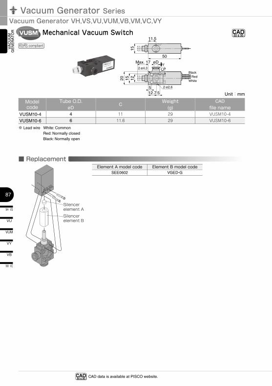
Vacuum Generator SeriesVacuum Generator VH,VS,VU,VUM,VB,VM,VC,VY
VH · VS
87
VU
VB
VM · VC
VY
VUM
VAC
UU
M
GEN
ERA
TOR Mechanical Vacuum SwitchVUSM CAD
-2D & 3D-
■ Replacement Element
Silencer element ASilencer element B
CAD-2D & 3D- CAD data is available at PISCO website.
Element A model codeSEE0602
Element B model codeVGED-G
Unit:mm
Model code
Tube O.D.øD
CWeight
(g)CAD
file nameVUSM10-4 4 11 29 VUSM10-4
VUSM10-6 6 11.6 29 VUSM10-6
※ Lead wire White: CommonRed: Normally closedBlack: Normally open
compliant
50
11.5
Max. 17 øD2-ø4.3
2-ø2.6512.7 5
1512
C
1520
BlackRed
White
V
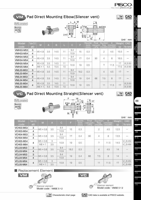
88
VN
VZ
VQ
VX
VJ
VK
VG
VM · VC
VB
VU
VH · VS
VY
VUM
VRL
VAC
UU
M
GEN
ERA
TOR
EXTERNAL VACUUM CONTROLLER
VAC
UU
MPA
DVACUUM
ACCESSORIES
Pad Direct Mounting Elbow(Silencer vent)
Pad Direct Mounting Straight(Silencer vent)
VM
VC
■ Replacement Element
Silencer elementModel code:VMSE 5×2
Silencer elementModel code:VMSE 5×2
VM VC
CAD-2D & 3D-
CAD-2D & 3D-
Unit:mm
Model code
Tube O.D.øD
M A B L C FNozzle bore(mm)
Final vacuum
(-kPa)
Suction flow
(l/min(ANR))
Air consumption(l/min(ANR))
Weight(g)
CAD
file nameVMH03-M53 3
M5×0.8 3.5 14.5 119.4
15 0.3
90
2 4.5 15.5 ーVMH03-M54 4 10.9
VMH04-M53 3M5×0.8 3.5 14.5 11
9.417 0.4 4 8 16.5 ー
VMH04-M54 4 10.9
VMH05-M544
M5×0.8 3.5 14.5 1110.9 19 0.5 7 11.5
17 VM_05-M54
VMH05-M64 M6×1 5.5 15.5 10 17.5 VM_05-M64
VML03-M53 3M5×0.8 3.5 14.5 11
9.418.2 0.3
66
4 4.5 17 ーVML03-M54 4 10.9
VML04-M53 3M5×0.8 3.5 14.5 11
9.419 0.4 7.5 8 17 ー
VML04-M54 4 10.9
VML05-M544
M5×0.8 3.5 14.5 1110.9 19 0.5 11 11.5 17
VM_05-M54
VML05-M64 M6×1 5.5 15.5 10 VM_05-M64
Unit:mm
Model code
Tube O.D.øD
M A C FNozzle bore(mm)
Final vacuum
(-kPa)
Suction flow
(l/min(ANR))
Air consumption(l/min(ANR))
Weight(g)
CAD
file nameVCH03-M53 3
M5×0.8 3.59.4
15 0.3
90
2 4.5 12.5 ーVCH03-M54 4 10.9
VCH04-M53 3M5×0.8 3.5
9.417 0.4 4 8 13.5 ー
VCH04-M54 4 10.9
VCH05-M544
M5×0.8 310.9 19 0.5 7 11.5 14.5
VC_05-M54
VCH05-M64 M6×1 3.5 VC_05-M64
VCL03-M53 3M5×0.8 3.5
9.418.2 0.3
66
4 4.5 14 ーVCL03-M54 4 10.9
VCL04-M53 3M5×0.8 3.5
9.419 0.4 7.5 8 14 ー
VCL04-M54 4 10.9
VCL05-M544
M5×0.8 310.9 19 0.5 11 11.5 17
VC_05-M54
VCL05-M64 M6×1 3.5 VC_05-M64
compliant
compliant
Energysaving
type
Energysaving
type
ChartP.60, P.89
ChartP.60, P.89
CAD-2D & 3D- CAD data is available at PISCO website.Characteristic chart page Chart
P.000
ø8
øD
9106
F16B C
□8AL M
VP EXH
2-H7
ø8
øD
15.5
A6.
5
F 16□8C
M
V
PEXHH7
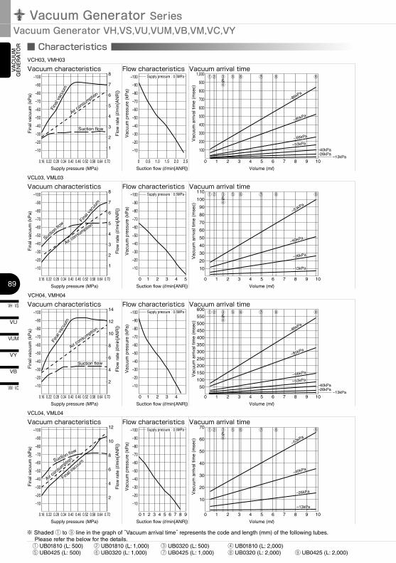
Vacuum Generator SeriesVacuum Generator VH,VS,VU,VUM,VB,VM,VC,VY
VH · VS
89
VU
VB
VM · VC
VY
VUM
VAC
UU
M
GEN
ERA
TOR ■ Characteristics
※ Shaded ① to ⑨ line in the graph of “Vacuum arrival time” represents the code and length (mm) of the following tubes. Please refer the below for the details. ① UB01810 (L: 500) ② UB01810 (L: 1,000) ③ UB0320 (L: 500) ④ UB01810 (L: 2,000) ⑤ UB0425 (L: 500) ⑥ UB0320 (L: 1,000) ⑦ UB0425 (L: 1,000) ⑧ UB0320 (L: 2,000) ⑨ UB0425 (L: 2,000)
0.16 0.22 0.28 0.34 0.40 0.46 0.52 0.58 0.64 0.70 0 0 1 2 3 4 5 6 7 8 9 10–13kPa
0.5 1.0 1.5 2.0 2.5
–10
Supply pressure (MPa) Suction flow (l/min[ANR]) Volume (ml)
Fin
al v
acuu
m (
kPa)
Vac
uum
pre
ssur
e (k
Pa)
Flo
w r
ate
(l/m
in[A
NR
])
VCH03, VMH03
Vacuum characteristics Flow characteristics
1
2
3
4
5
6
7
8Vacuum arrival time
Supply pressure (MPa) Suction flow (l/min[ANR])
Fin
al v
acuu
m (
kPa)
Vac
uum
pre
ssur
e (k
Pa)
Flo
w r
ate
(l/m
in[A
NR
])
VCH04, VMH04
Vacuum characteristics Flow characteristics
Supply pressure:0.5MPa
–20
–30
–40
–50
–60
–70
–80
–90
–100
–10
Vac
uum
arr
ival
tim
e (m
sec)
100
200
300
400
500
600
700
800
900
1,000
–20
–30
–40
–50
–60
–70
–80
–90
–100
Suction flow
Air consu
mption
Fina
l vac
uum
Suction flow
Air consu
mption
Fina
l vac
uum
0.16 0.22 0.28 0.34 0.40 0.46 0.52 0.58 0.64 0.70 0 1 2 3 4 5
–10
Supply pressure (MPa) Suction flow (l/min[ANR])
Fin
al v
acuu
m (
kPa)
Vac
uum
pre
ssur
e (k
Pa)
Flo
w r
ate
(l/m
in[A
NR
])
VCL03, VML03
Vacuum characteristics Flow characteristics
1
2
4
6
8
10
12
14
2
3
4
5
6
7
8 Supply pressure:0.5MPa
–20
–30
–40
–50
–60
–70
–80
–90
–100
–10
–20
–30
–40
–50
–60
–70
–80
–90
–100
0.16 0.22 0.28 0.34 0.40 0.46 0.52 0.58 0.64 0.70
–10
–20
–30
–40
–50
–60
–70
–80
–90
–100
Suction flo
w
Air consu
mption
Fina
l vac
uum
Suction flo
w
Suction flowSuction flow
Air consu
mption
Air consu
mption
Air consu
mption
Fina
l vac
uum
Fina
l vac
uum
Fina
l vac
uum
0 1 2 3 4
Supply pressure:0.5MPa
–10
–20
–30
–40
–50
–60
–70
–80
–90
–100
–86kPa
–80kPa
–66kPa
–53kPa
–40kPa–26kPa
–86kPa
–80kPa
–66kPa
–53kPa
–40kPa–26kPa
①② ③&④
⑤ ⑥ ⑦ ⑧ ⑨
0 1 2 3 4 5 6 7 8 9 10–13kPa
Volume (ml)
Vacuum arrival time
Vac
uum
arr
ival
tim
e (m
sec)
50
600
100
150
200
250
300
350
400
450
500
550
–86kPa
–80kPa
–66kPa
–53kPa–40kPa–26kPa
–86kPa
–80kPa
–66kPa
–53kPa–40kPa–26kPa
0 1 2 3 4 5 6 7 8 9 10
Volume (ml)
Vacuum arrival timeV
acuu
m a
rriv
al ti
me
(mse
c)
10
110
20
30
40
50
60
70
80
90
100
–53kPa
–40kPa
–26kPa
–53kPa
–40kPa
–26kPa
–13kPa–13kPa
0.16 0.22 0.28 0.34 0.40 0.46 0.52 0.58 0.64 0.70 0 1
–10
Supply pressure (MPa) Suction flow (l/min[ANR])
Fin
al v
acuu
m (
kPa)
Vac
uum
pre
ssur
e (k
Pa)
Flo
w r
ate
(l/m
in[A
NR
])
VCL04, VML04
Vacuum characteristics Flow characteristics
2
4
6
8
10
12
2 3 4 5 6 7 8 9
Supply pressure:0.5MPa
–20
–30
–40
–50
–60
–70
–80
–90
–100
–10
–20
–30
–40
–50
–60
–70
–80
–90
–100
Suction flow
Air consu
mption
Final vacu
umSuction flow
Air consu
mption
Final vacu
um
0 1 2 3 4 5 6 7 8 9 10
Volume (ml)
Vacuum arrival time
Vac
uum
arr
ival
tim
e (m
sec)
10
70
20
30
40
50
60–53kPa
–40kPa
–26kPa
–53kPa
–40kPa
–26kPa
–13kPa–13kPa
①② ③&④
⑤ ⑥ ⑦ ⑧ ⑨
①② ③&④
⑤ ⑥ ⑦ ⑧ ⑨
①② ③&④
⑤ ⑥ ⑦ ⑧ ⑨
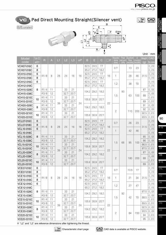
90
VN
VZ
VQ
VX
VJ
VK
VG
VM · VC
VB
VU
VH · VS
VY
VUM
VRL
VAC
UU
M
GEN
ERA
TOR
EXTERNAL VACUUM CONTROLLER
VAC
UU
MPA
DVACUUM
ACCESSORIES
øP
C
L1 L2L3
A
øD
BE
□F
V
P EXH
R
Pad Direct Mounting Straight(Silencer vent)VC CAD-2D & 3D- Chart
P.60
Unit:mm
Model code
Tube O.D.øD1
R A L1 L2 L3 øP B E C □FNozzle bore(mm)
Final vacuum
(-kPa)
Suction flow
(l/min(ANR))
Air consumption(l/min(ANR))
Weight(g)
CAD
file nameVCH07-016C 6
R1/8 8 28 24 16 16
62.5 24.5 17
16
0.7
93
13 23
31.5
VC_-016C
VCH07-018C 8 65.2 27.2 18.2 VC_-018C
VCH10-016C 6 62.5 24.5 171 28 46
VC_-016C
VCH10-018C 8 65.2 27.2 18.2 VC_-018C
VCH12-016C 6 62.5 24.5 171.2 38 70
VC_-016C
VCH12-018C8
65.2 27.2 18.2 VC_-018C
VCH15-028C R1/4 11
39
33 21
24
104.2 29.2 18.2
22
1.5 63 100
87 VC_-028C
VCH15-038C R3/8 12 32.7 20.788
VC_-038C
VCH15-0210C10
R1/4 11 33 21105.9 30.9 20.7
VC_-0210C
VCH15-0310C R3/8 12 32.7 20.7 89 VC_-0310C
VCH20-028C8
R1/4 11 33 21104.2 29.2 18.2
2 110 200
91 VC_-028C
VCH20-038C R3/8 12 32.7 20.7 92 VC_-038C
VCH20-0210C10
R1/4 11 33 21105.9 30.9 20.7
92.5 VC_-0210C
VCH20-0310C R3/8 12 32.7 20.7 93.5 VC_-0310C
VCL07-016C 6
R1/8 8 28 24 16 16
62.5 24.5 17
160.7
66
26 2331.5
VC_-016C
VCL07-018C 8 65.2 27.2 18.2 VC_-018C
VCL10-016C 6 62.5 24.5 171 42 46
VC_-016C
VCL10-018C8
65.2 27.2 18.2 VC_-018C
VCL15-028C R1/4 11
39
33 21
24
104.2 29.2 18.2
22
1.5 95 100
85 VC_-028C
VCL15-038C R3/8 12 32.7 20.7 86 VC_-038C
VCL15-0210C10
R1/4 11 33 21105.9 30.9 20.7
86.5 VC_-0210C
VCL15-0310C R3/8 12 32.7 20.7 87.5 VC_-0310C
VCL20-028C8
R1/4 11 33 21104.2 29.2 18.2
2 180 200
87 VC_-028C
VCL20-038C R3/8 12 32.7 20.788
VC_-038C
VCL20-0210C10
R1/4 11 33 21105.9 30.9 20.7
VC_-0210C
VCL20-0310C R3/8 12 32.7 20.7 89 VC_-0310C
VCE07-016C 6
R1/8 8 28 24 16 16
62.5 24.5 17
16
0.7
92
10.5 17
31.5
VC_-016C
VCE07-018C 8 65.2 27.2 18.2 VC_-018C
VCE10-016C 6 62.5 24.5 171 21 34
VC_-016C
VCE10-018C 8 65.2 27.2 18.2 VC_-018C
VCE12-016C 6 62.5 24.5 171.2 27 47
VC_-016C
VCE12-018C8
65.2 27.2 18.2 VC_-018C
VCE15-028C R1/4 11
39
33 21
24
104.2 29.2 18.2
22
1.5 42 70
87.5 VC_-028C
VCE15-038C R3/8 12 32.7 20.788.5
VC_-038C
VCE15-0210C10
R1/4 11 33 21105.9 30.9 20.7
VC_-0210C
VCE15-0310C R3/8 12 32.7 20.7 89.5 VC_-0310C
VCE20-028C8
R1/4 11 33 21104.2 29.2 18.2
2 84 150
92.5 VC_-028C
VCE20-038C R3/8 12 32.7 20.7 93.5 VC_-038C
VCE20-0210C10
R1/4 11 33 21105.9 30.9 20.7
94 VC_-0210C
VCE20-0310C R3/8 12 32.7 20.7 95 VC_-0310C
※ “L2” and “L3” are reference dimensions after tightening the thread.
compliant
CAD-2D & 3D- CAD data is available at PISCO website.Characteristic chart page Chart
P.000
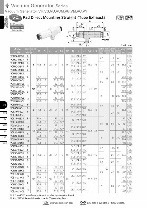
Vacuum Generator SeriesVacuum Generator VH,VS,VU,VUM,VB,VM,VC,VY
VH · VS
91
VU
VB
VM · VC
VY
VUM
VAC
UU
M
GEN
ERA
TOR
øP
øD
2C2
EXH
C1
L1 L2L3
A
øD
1
BE
□F
V
P
R
Pad Direct Mounting Straight (Tube Exhaust)VC CAD-2D & 3D- Chart
P.60
Unit:mm
Model code
Tube O.D.øD1
Tube O.D.øD2
R A L1 L2 L3 øP B E C1 C2 □FNozzle bore(mm)
Final vacuum
(-kPa)
Suction flow
(l/min(ANR))
Air consumption(l/min(ANR))
Weight(g)
CAD
file nameVCH07-016CJ 6
8 R1/8 8 28 24 16 16
64.6 24.5 17
18.2 16
0.7
93
13 23
36.5
VC_-016CJ
VCH07-018CJ 8 67.3 27.2 18.2 VC_-018CJ
VCH10-016CJ 6 64.6 24.5 171 28 46
VC_-016CJ
VCH10-018CJ 8 67.3 27.2 18.2 VC_-018CJ
VCH12-016CJ 6 64.6 24.5 171.2 38 70
VC_-016CJ
VCH12-018CJ8
67.3 27.2 18.2 VC_-018CJ
VCH15-028CJ
12
R1/4 11
38
32 21
22
94 29.2 18.2
23.3 22
1.5 63 100
98.5 VC_-028CJ
VCH15-038CJ R3/8 12 31.7 20.799.5
VC_-038CJ
VCH15-0210CJ10
R1/4 11 32 2195.7 30.9 20.7
VC_-0210CJ
VCH15-0310CJ R3/8 12 31.7 20.7 100.5 VC_-0310CJ
VCH20-028CJ8
R1/4 11 32 2194 29.2 18.2
2 110 200
103 VC_-028CJ
VCH20-038CJ R3/8 12 31.7 20.7104
VC_-038CJ
VCH20-0210CJ10
R1/4 11 32 2195.7 30.9 20.7
VC_-0210CJ
VCH20-0310CJ R3/8 12 31.7 20.7 105 VC_-0310CJ
VCL07-016CJ 6
8 R1/8 8 28 24 16 16
64.6 24.5 17
18.2 160.7
66
26 2336.5
VC_-016CJ
VCL07-018CJ 8 67.3 27.2 18.2 VC_-018CJ
VCL10-016CJ 6 64.6 24.5 171 42 46
VC_-016CJ
VCL10-018CJ8
67.3 27.2 18.2 VC_-018CJ
VCL15-028CJ
12
R1/4 11
38
32 21
22
94 29.2 18.2
23.3 22
1.5 95 100
97 VC_-028CJ
VCL15-038CJ R3/8 12 31.7 20.798
VC_-038CJ
VCL15-0210CJ10
R1/4 11 32 2195.7 30.9 20.7
VC_-0210CJ
VCL15-0310CJ R3/8 12 31.7 20.7 99 VC_-0310CJ
VCL20-028CJ8
R1/4 11 32 2194 29.2 18.2
2 180 200
98.5 VC_-028CJ
VCL20-038CJ R3/8 12 31.7 20.7 99.5 VC_-038CJ
VCL20-0210CJ10
R1/4 11 32 2195.7 30.9 20.7
100 VC_-0210CJ
VCL20-0310CJ R3/8 12 31.7 20.7 100.5 VC_-0310CJ
VCE07-016CJ 6
8 R1/8 8 28 24 16 16
64.6 24.5 17
18.2 16
0.7
92
10.5 17
36.5
VC_-016CJ
VCE07-018CJ 8 67.3 27.2 18.2 VC_-018CJ
VCE10-016CJ 6 64.6 24.5 171 21 34
VC_-016CJ
VCE10-018CJ 8 67.3 27.2 18.2 VC_-018CJ
VCE12-016CJ 6 64.6 24.5 171.2 27 47
VC_-016CJ
VCE12-018CJ8
67.3 27.2 18.2 VC_-018CJ
VCE15-028CJ
12
R1/4 11
38
32 21
22
94 29.2 18.2
23.3 22
1.5 42 70
99.5 VC_-028CJ
VCE15-038CJ R3/8 12 31.7 20.7100.5
VC_-038CJ
VCE15-0210CJ10
R1/4 11 32 2195.7 30.9 20.7
VC_-0210CJ
VCE15-0310CJ R3/8 12 31.7 20.7 101.5 VC_-0310CJ
VCE20-028CJ8
R1/4 11 32 2194 29.2 18.2
2 84 150
104.5 VC_-028CJ
VCE20-038CJ R3/8 12 31.7 20.7105.5
VC_-038CJ
VCE20-0210CJ10
R1/4 11 32 2195.7 30.9 20.7
VC_-0210CJ
VCE20-0310CJ R3/8 12 31.7 20.7 106.5 VC_-0310CJ
※ “L2” and “L3” are reference dimensions after tightening the thread.※ Add “-S3” at the end of model code for “Copper alloy free” .
compliantCopper alloy free
Selectable
CAD-2D & 3D- CAD data is available at PISCO website.Characteristic chart page Chart
P.000
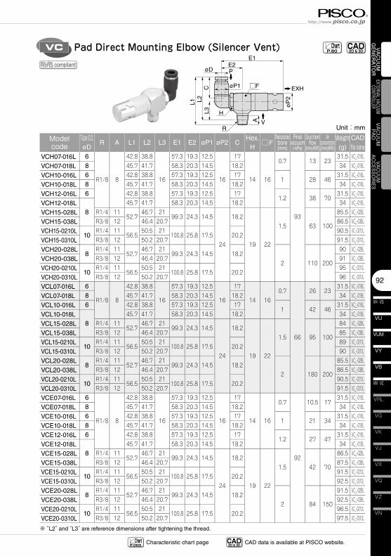
92
VN
VZ
VQ
VX
VJ
VK
VG
VM · VC
VB
VU
VH · VS
VY
VUM
VRL
VAC
UU
M
GEN
ERA
TOR
EXTERNAL VACUUM CONTROLLER
VAC
UU
MPA
DVACUUM
ACCESSORIES
øP
2
C
L1 L2L3
A
øD
øP1
E1E2
□F
V
P
EXH
H
R
Pad Direct Mounting Elbow (Silencer Vent)VC CAD-2D & 3D- Chart
P.60
Unit:mm
Model code
Tube O.D.øD
R A L1 L2 L3 E1 E2 øP1 øP2 CHex.
H□F
Nozzle bore(mm)
Final vacuum
(-kPa)
Suction flow
(l/min(ANR))
Air consumption(l/min(ANR))
Weight(g)
CAD
file nameVCH07-016L 6
R1/8 8
42.8 38.8
16
57.3 19.3 12.5
16
17
14 16
0.7
93
13 2331.5 VC_-016L
VCH07-018L 8 45.7 41.7 58.3 20.3 14.5 18.2 34 VC_-018L
VCH10-016L 6 42.8 38.8 57.3 19.3 12.5 171 28 46
31.5 VC_-016L
VCH10-018L 8 45.7 41.7 58.3 20.3 14.5 18.2 34 VC_-018L
VCH12-016L 6 42.8 38.8 57.3 19.3 12.5 171.2 38 70
31.5 VC_-016L
VCH12-018L8
45.7 41.7 58.3 20.3 14.5 18.2 34 VC_-018L
VCH15-028L R1/4 1152.7
46.7 2199.3 24.3 14.5
24
18.2
19 22
1.5 63 100
85.5 VC_-028L
VCH15-038L R3/8 12 46.4 20.7 86.5 VC_-038L
VCH15-0210L10
R1/4 1156.5
50.5 21100.8 25.8 17.5 20.2
90.5 VC_-0210L
VCH15-0310L R3/8 12 50.2 20.7 91.5 VC_-0310L
VCH20-028L8
R1/4 1152.7
46.7 2199.3 24.3 14.5 18.2
2 110 200
90 VC_-028L
VCH20-038L R3/8 12 46.4 20.7 91 VC_-038L
VCH20-0210L10
R1/4 1156.5
50.5 21100.8 25.8 17.5 20.2
95 VC_-0210L
VCH20-0310L R3/8 12 50.2 20.7 96 VC_-0310L
VCL07-016L 6
R1/8 8
42.8 38.8
16
57.3 19.3 12.5
16
17
14 160.7
66
26 2331.5 VC_-016L
VCL07-018L 8 45.7 41.7 58.3 20.3 14.5 18.2 34 VC_-018L
VCL10-016L 6 42.8 38.8 57.3 19.3 12.5 171 42 46
31.5 VC_-016L
VCL10-018L8
45.7 41.7 58.3 20.3 14.5 18.2 34 VC_-018L
VCL15-028L R1/4 1152.7
46.7 2199.3 24.3 14.5
24
18.2
19 22
1.5 95 100
84 VC_-028L
VCL15-038L R3/8 12 46.4 20.7 85 VC_-038L
VCL15-0210L10
R1/4 1156.5
50.5 21100.8 25.8 17.5 20.2
89 VC_-0210L
VCL15-0310L R3/8 12 50.2 20.7 90 VC_-0310L
VCL20-028L8
R1/4 1152.7
46.7 2199.3 24.3 14.5 18.2
2 180 200
85.5 VC_-028L
VCL20-038L R3/8 12 46.4 20.7 86.5 VC_-038L
VCL20-0210L10
R1/4 1156.5
50.5 21100.8 25.8 17.5 20.2
90.5 VC_-0210L
VCL20-0310L R3/8 12 50.2 20.7 91.5 VC_-0310L
VCE07-016L 6
R1/8 8
42.8 38.8
16
57.3 19.3 12.5
16
17
14 16
0.7
92
10.5 1731.5 VC_-016L
VCE07-018L 8 45.7 41.7 58.3 20.3 14.5 18.2 34 VC_-018L
VCE10-016L 6 42.8 38.8 57.3 19.3 12.5 171 21 34
31.5 VC_-016L
VCE10-018L 8 45.7 41.7 58.3 20.3 14.5 18.2 34 VC_-018L
VCE12-016L 6 42.8 38.8 57.3 19.3 12.5 171.2 27 47
31.5 VC_-016L
VCE12-018L8
45.7 41.7 58.3 20.3 14.5 18.2 34 VC_-018L
VCE15-028L R1/4 1152.7
46.7 2199.3 24.3 14.5
24
18.2
19 22
1.5 42 70
86.5 VC_-028L
VCE15-038L R3/8 12 46.4 20.7 87.5 VC_-038L
VCE15-0210L10
R1/4 1156.5
50.5 21100.8 25.8 17.5 20.2
91.5 VC_-0210L
VCE15-0310L R3/8 12 50.2 20.7 92.5 VC_-0310L
VCE20-028L8
R1/4 1152.7
46.7 2199.3 24.3 14.5 18.2
2 84 150
91.5 VC_-028L
VCE20-038L R3/8 12 46.4 20.7 92.5 VC_-038L
VCE20-0210L10
R1/4 1156.5
50.5 21100.8 25.8 17.5 20.2
96.5 VC_-0210L
VCE20-0310L R3/8 12 50.2 20.7 97.5 VC_-0310L
※ “L2” and “L3” are reference dimensions after tightening the thread.
compliant
CAD-2D & 3D- CAD data is available at PISCO website.Characteristic chart page Chart
P.000
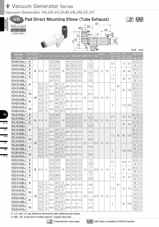
Vacuum Generator SeriesVacuum Generator VH,VS,VU,VUM,VB,VM,VC,VY
VH · VS
93
VU
VB
VM · VC
VY
VUM
VAC
UU
M
GEN
ERA
TOR
øP
2ø
D2
C1
L1 L2L3
A
øD1
øP1
E1
C2E2
□F
V
PEXH
H R
Pad Direct Mounting Elbow (Tube Exhaust)VC CAD-2D & 3D- Chart
P.60
Unit:mm
Model code
Tube O.D.øD1
Tube O.D.øD2
R A L1 L2 L3 E1 E2 øP1 øP2 C1 C2Hex.
H□F
Nozzle bore(mm)
Final vacuum
(-kPa)
Suction flow
(l/min(ANR))
Air consumption(l/min(ANR))
Weight(g)
CAD
file nameVCH07-016LJ 6
8 R1/8 8
42.8 38.8
16
59.4 19.3 12.5
16
17
18.2 14 16
0.7
93
13 2335.5 VC_-016LJ
VCH07-018LJ 8 45.7 41.7 60.4 20.3 14.5 18.2 38 VC_-018LJ
VCH10-016LJ 6 42.8 38.8 59.4 19.3 12.5 171 28 46
35.5 VC_-016LJ
VCH10-018LJ 8 45.7 41.7 60.4 20.3 14.5 18.2 38 VC_-018LJ
VCH12-016LJ 6 42.8 38.8 59.4 19.3 12.5 171.2 38 70
35.5 VC_-016LJ
VCH12-018LJ8
45.7 41.7 60.4 20.3 14.5 18.2 38 VC_-018LJ
VCH15-028LJ
12
R1/4 1152.7
46.7 2189.1 24.3 14.5
22
18.2
23.3 19 22
1.5 63 100
97.5 VC_-028LJ
VCH15-038LJ R3/8 12 46.4 20.7 98.5 VC_-038LJ
VCH15-0210LJ10
R1/4 1156.5
50.5 2190.6 25.8 17.5 20.2
102 VC_-0210LJ
VCH15-0310LJ R3/8 12 50.2 20.7 103 VC_-0310LJ
VCH20-028LJ8
R1/4 1152.7
46.7 2189.1 24.3 14.5 18.2
2 110 200
101.5 VC_-028LJ
VCH20-038LJ R3/8 12 46.4 20.7 102.5 VC_-038LJ
VCH20-0210LJ10
R1/4 1156.5
50.5 2190.6 25.8 17.5 20.2
106.5 VC_-0210LJ
VCH20-0310LJ R3/8 12 50.2 20.7 107.5 VC_-0310LJ
VCL07-016LJ 6
8 R1/8 8
42.8 38.8
16
59.4 19.3 12.5
16
17
18.2 14 160.7
66
26 2335.5 VC_-016LJ
VCL07-018LJ 8 45.7 41.7 60.4 20.3 14.5 18.2 38 VC_-018LJ
VCL10-016LJ 6 42.8 38.8 59.4 19.3 12.5 171 42 46
35.5 VC_-016LJ
VCL10-018LJ8
45.7 41.7 60.4 20.3 14.5 18.2 38 VC_-018LJ
VCL15-028LJ
12
R1/4 1152.7
46.7 2189.1 24.3 14.5
22
18.2
23.3 19 22
1.5 95 100
95.5 VC_-028LJ
VCL15-038LJ R3/8 12 46.4 20.7 96.5 VC_-038LJ
VCL15-0210LJ10
R1/4 1156.5
50.5 2190.6 25.8 17.5 20.2
100.5 VC_-0210LJ
VCL15-0310LJ R3/8 12 50.2 20.7 101.5 VC_-0310LJ
VCL20-028LJ8
R1/4 1152.7
46.7 2189.1 24.3 14.5 18.2
2 180 200
97 VC_-028LJ
VCL20-038LJ R3/8 12 46.4 20.7 98 VC_-038LJ
VCL20-0210LJ10
R1/4 1156.5
50.5 2190.6 25.8 17.5 20.2
102 VC_-0210LJ
VCL20-0310LJ R3/8 12 50.2 20.7 103 VC_-0310LJ
VCE07-016LJ 6
8 R1/8 8
42.8 38.8
16
59.4 19.3 12.5
16
17
18.2 14 16
0.7
92
10.5 1735.5 VC_-016LJ
VCE07-018LJ 8 45.7 41.7 60.4 20.3 14.5 18.2 38 VC_-018LJ
VCE10-016LJ 6 42.8 38.8 59.4 19.3 12.5 171 21 34
35.5 VC_-016LJ
VCE10-018LJ 8 45.7 41.7 60.4 20.3 14.5 18.2 38 VC_-018LJ
VCE12-016LJ 6 42.8 38.8 59.4 19.3 12.5 171.2 27 47
35.5 VC_-016LJ
VCE12-018LJ8
45.7 41.7 60.4 20.3 14.5 18.2 38 VC_-018LJ
VCE15-028LJ
12
R1/4 1152.7
46.7 2189.1 24.3 14.5
22
18.2
23.3 19 22
1.5 42 70
98 VC_-028LJ
VCE15-038LJ R3/8 12 46.4 20.7 99 VC_-038LJ
VCE15-0210LJ10
R1/4 1156.5
50.5 2190.6 25.8 17.5 20.2
103 VC_-0210LJ
VCE15-0310LJ R3/8 12 50.2 20.7 104 VC_-0310LJ
VCE20-028LJ8
R1/4 1152.7
46.7 2189.1 24.3 14.5 18.2
2 84 150
103 VC_-028LJ
VCE20-038LJ R3/8 12 46.4 20.7 104 VC_-038LJ
VCE20-0210LJ10
R1/4 1156.5
50.5 2190.6 25.8 17.5 20.2
108 VC_-0210LJ
VCE20-0310LJ R3/8 12 50.2 20.7 109 VC_-0310LJ
※ “L2” and “L3” are reference dimensions after tightening the thread.※ Add “-S3” at the end of model code for “Copper alloy free” .
compliantCopper alloy free
Selectable
CAD-2D & 3D- CAD data is available at PISCO website.Characteristic chart page Chart
P.000
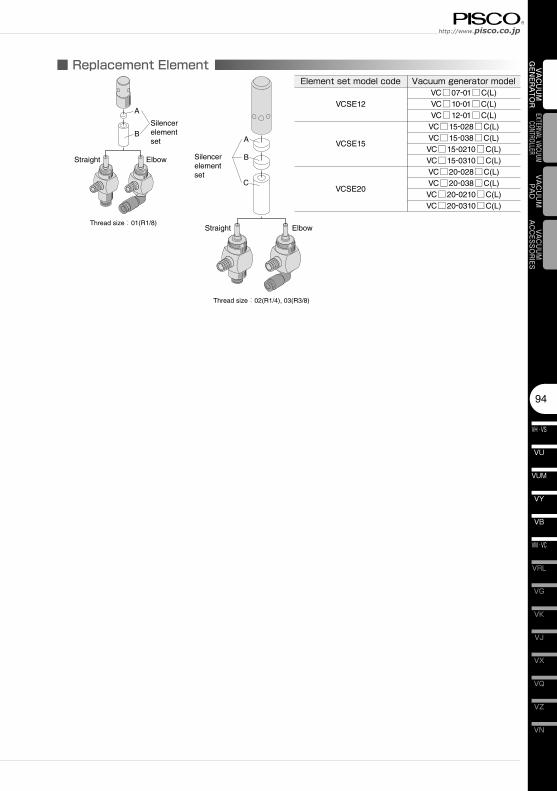
94
VN
VZ
VQ
VX
VJ
VK
VG
VM · VC
VB
VU
VH · VS
VY
VUM
VRL
VAC
UU
M
GEN
ERA
TOR
EXTERNAL VACUUM CONTROLLER
VAC
UU
MPA
DVACUUM
ACCESSORIES
■ Replacement Element
Straight Elbow
Straight Elbow
A
BSilencer element set A
B
C
Silencer element set
Thread size:01(R1/8)
Thread size:02(R1/4), 03(R3/8)
Element set model code
VCSE12
VCSE15
VCSE20
Vacuum generator modelVC□07-01□C(L)VC□10-01□C(L)VC□12-01□C(L)
VC□15-028□C(L)VC□15-038□C(L)VC□15-0210□C(L)VC□15-0310□C(L)VC□20-028□C(L)VC□20-038□C(L)VC□20-0210□C(L)VC□20-0310□C(L)
Vacuum Generator SeriesVacuum Generator VH,VS,VU,VUM,VB,VM,VC,VY
VH · VS
95
VU
VB
VM · VC
VY
VUM
VAC
UU
M
GEN
ERA
TOR
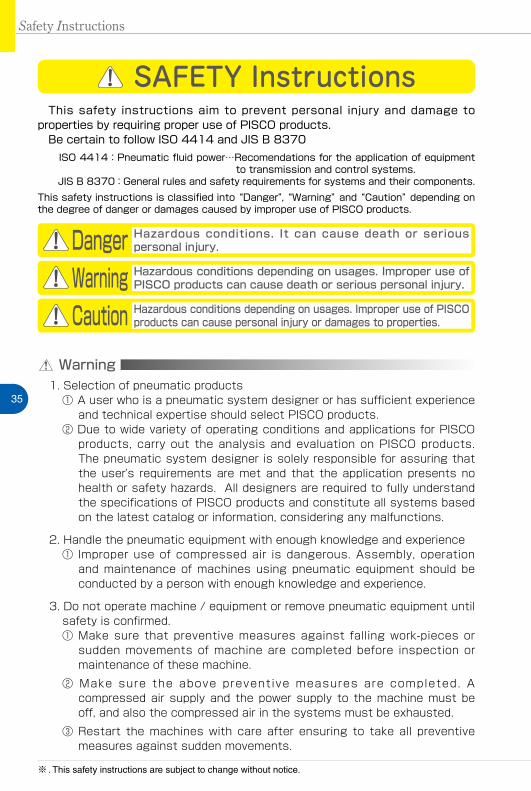
35
Safety Instructions
SAFETY Instructions
Warning
This safety instructions aim to prevent personal injury and damage to properties by requiring proper use of PISCO products. Be certain to follow ISO 4414 and JIS B 8370
ISO 4414:Pneumatic fluid power…Recomendations for the application of equipment to transmission and control systems.
JIS B 8370:General rules and safety requirements for systems and their components.This safety instructions is classified into “Danger”, “Warning” and “Caution” depending on the degree of danger or damages caused by improper use of PISCO products.
1. Selection of pneumatic products① A user who is a pneumatic system designer or has sufficient experience
and technical expertise should select PISCO products.② Due to wide variety of operating conditions and applications for PISCO
products, carry out the analysis and evaluation on PISCO products. The pneumatic system designer is solely responsible for assuring that the user's requirements are met and that the application presents no health or safety hazards. All designers are required to fully understand the specifications of PISCO products and constitute all systems based on the latest catalog or information, considering any malfunctions.
2. Handle the pneumatic equipment with enough knowledge and experience① Improper use of compressed air is dangerous. Assembly, operation
and maintenance of machines using pneumatic equipment should be conducted by a person with enough knowledge and experience.
3. Do not operate machine / equipment or remove pneumatic equipment until safety is confirmed.① Make sure that preventive measures against falling work-pieces or
sudden movements of machine are completed before inspection or maintenance of these machine.
② Make sure the above preventive measures are completed. A compressed air supply and the power supply to the machine must be off, and also the compressed air in the systems must be exhausted.
③ Restart the machines with care after ensuring to take all preventive measures against sudden movements.
Danger Hazardous conditions. It can cause death or serious personal injury.
Warning Hazardous conditions depending on usages. Improper use of PISCO products can cause death or serious personal injury.
Caution Hazardous conditions depending on usages. Improper use of PISCO products can cause personal injury or damages to properties.
※ . This safety instructions are subject to change without notice.
http://www.pisco.co.jphttp://www.pisco.co.jp
36
Disclaimer1. PISCO does not take any responsibility for any incidental or indirect
loss, such as production line stop, interruption of business, loss of benefits, personal injury, etc., caused by any failure on use or application of PISCO products.
2. PISCO does not take any responsibility for any loss caused by natural disasters, fires not related to PISCO products, acts by third parties, and intentional or accidental damages of PISCO products due to incorrect usage.
3. PISCO does not take any responsibility for any loss caused by improper usage of PISCO products such as exceeding the specification limit or not following the usage the published instructions and catalog allow.
4. PISCO does not take any responsibility for any loss caused by remodeling of PISCO products, or by combinational use with non-PISCO products and other software systems.
5. The damages caused by the defect of Pisco products shall be covered but limited to the full amount of the PISCO products paid by the customer.
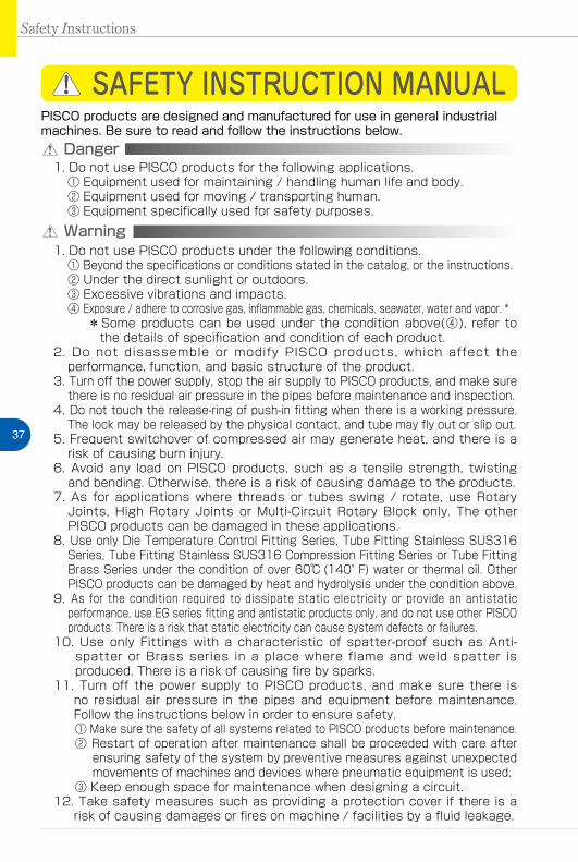
37
Safety Instructions
SAFETY INSTRUCTION MANUAL
Danger1. Do not use PISCO products for the following applications.
① Equipment used for maintaining / handling human life and body.② Equipment used for moving / transporting human.③ Equipment specifically used for safety purposes.
Warning1. Do not use PISCO products under the following conditions.
① Beyond the specifications or conditions stated in the catalog, or the instructions.② Under the direct sunlight or outdoors.③ Excessive vibrations and impacts.④ Exposure / adhere to corrosive gas, inflammable gas, chemicals, seawater, water and vapor. *
* Some products can be used under the condition above(④), refer to the details of specification and condition of each product.
2. Do not disassemble or modify PISCO products, which affect the performance, function, and basic structure of the product.
3. Turn off the power supply, stop the air supply to PISCO products, and make sure there is no residual air pressure in the pipes before maintenance and inspection.
4. Do not touch the release-ring of push-in fitting when there is a working pressure. The lock may be released by the physical contact, and tube may fly out or slip out.
5. Frequent switchover of compressed air may generate heat, and there is a risk of causing burn injury.
6. Avoid any load on PISCO products, such as a tensile strength, twisting and bending. Otherwise, there is a risk of causing damage to the products.
7. As for applications where threads or tubes swing / rotate, use Rotary Joints, High Rotary Joints or Multi-Circuit Rotary Block only. The other PISCO products can be damaged in these applications.
8. Use only Die Temperature Control Fitting Series, Tube Fitting Stainless SUS316 Series, Tube Fitting Stainless SUS316 Compression Fitting Series or Tube Fitting Brass Series under the condition of over 60℃ (140°F) water or thermal oil. Other PISCO products can be damaged by heat and hydrolysis under the condition above.
9. As for the condition required to dissipate static electricity or provide an antistatic performance, use EG series fitting and antistatic products only, and do not use other PISCO products. There is a risk that static electricity can cause system defects or failures.
10. Use only Fittings with a characteristic of spatter-proof such as Anti-spatter or Brass series in a place where flame and weld spatter is produced. There is a risk of causing fire by sparks.
11. Turn off the power supply to PISCO products, and make sure there is no residual air pressure in the pipes and equipment before maintenance. Follow the instructions below in order to ensure safety.① Make sure the safety of all systems related to PISCO products before maintenance.② Restart of operation after maintenance shall be proceeded with care after
ensuring safety of the system by preventive measures against unexpected movements of machines and devices where pneumatic equipment is used.
③ Keep enough space for maintenance when designing a circuit.12. Take safety measures such as providing a protection cover if there is a
risk of causing damages or fires on machine / facilities by a fluid leakage.
PISCO products are designed and manufactured for use in general industrial machines. Be sure to read and follow the instructions below.
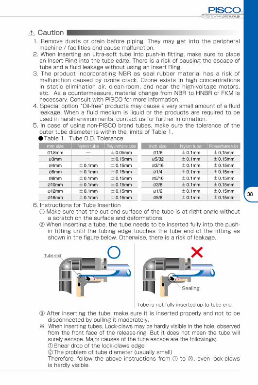
http://www.pisco.co.jphttp://www.pisco.co.jp
38
Caution1. Remove dusts or drain before piping. They may get into the peripheral
machine / facilities and cause malfunction.2. When inserting an ultra-soft tube into push-in fitting, make sure to place
an Insert Ring into the tube edge. There is a risk of causing the escape of tube and a fluid leakage without using an Insert Ring.
3. The product incorporating NBR as seal rubber material has a risk of malfunction caused by ozone crack. Ozone exists in high concentrations in static elimination air, clean-room, and near the high-voltage motors, etc. As a countermeasure, material change from NBR to HNBR or FKM is necessary. Consult with PISCO for more information.
4. Special option “Oil-free” products may cause a very small amount of a fluid leakage. When a fluid medium is liquid or the products are required to be used in harsh environments, contact us for further information.
5. In case of using non-PISCO brand tubes, make sure the tolerance of the outer tube diameter is within the limits of Table 1.
●Table 1. Tube O.D. Tolerancemm size Nylon tube Polyurethane tube inch size Nylon tube Polyurethane tubeø1.8mm ─ ±0.05mm ø1/8 ±0.1mm ±0.15mmø3mm ─ ±0.15mm ø5/32 ±0.1mm ±0.15mmø4mm ±0.1mm ±0.15mm ø3/16 ±0.1mm ±0.15mmø6mm ±0.1mm ±0.15mm ø1/4 ±0.1mm ±0.15mmø8mm ±0.1mm ±0.15mm ø5/16 ±0.1mm ±0.15mmø10mm ±0.1mm ±0.15mm ø3/8 ±0.1mm ±0.15mmø12mm ±0.1mm ±0.15mm ø1/2 ±0.1mm ±0.15mmø16mm ±0.1mm ±0.15mm ø5/8 ±0.1mm ±0.15mm
6. Instructions for Tube Insertion① Make sure that the cut end surface of the tube is at right angle without
a scratch on the surface and deformations.② When inserting a tube, the tube needs to be inserted fully into the push-
in fitting until the tubing edge touches the tube end of the fitting as shown in the figure below. Otherwise, there is a risk of leakage.
Tube end
Sealing
Tube is not fully inserted up to tube end.
③ After inserting the tube, make sure it is inserted properly and not to be disconnected by pulling it moderately.
※. When inserting tubes, Lock-claws may be hardly visible in the hole, observed from the front face of the release-ring. But it does not mean the tube will surely escape. Major causes of the tube escape are the followings; ①Shear drop of the lock-claws edge②The problem of tube diameter (usually small)Therefore, follow the above instructions from ① to ③, even lock-claws is hardly visible.
39
7. Instructions for Tube Disconnection① Make sure there is no air pressure inside of the tube, before disconnecting it.② Push the release-ring of the push-in fitting evenly and deeply enough to
pull out the tube toward oneself. By insufficient pushing of the release-ring, the tube may not be pulled out or damaged by scratch, and tube shavings may remain inside of the fitting, which may cause the leakage later.
8. Instructions for Installing a fitting① When installing a fitting, use proper tools to tighten a hexagonal-column
or an inner hexagonal socket. When inserting a hex key into the inner hexagonal socket of the fitting, be careful so that the tool does not touch lock-claws. The deformation of lock-claws may result in a poor performance of systems or an escape of the tube.
② Refer to Table 2 which shows the recommended tightening torque. Do not exceed these limits to tighten a thread. Excessive tightening may break the thread part or deform the gasket and cause a fluid leakage. Tightening thread with tightening torque lower than these limits may cause a loosened thread or a fluid leakage.
③ Adjust the tube direction while tightening thread within these limits, since some PISCO products are not rotatable after the installation.
●Table 2: Recommended tightening torque / Sealock color / Gasket materialsThread type Thread size Tightening torque Sealock color Gasket materials
Metric thread
M3×0.5 0.7N·m
─
SUS304NBR
M5×0.8 1.0 ~ 1.5N·mM6×1 2 ~ 2.7N·m
M3×0.5 0.5 ~ 0.6N·m
POMM5×0.8 1 ~ 1.5N·mM6×0.75 0.8 ~ 1N·mM8×0.75 1 ~ 2N·m
Taper pipe thread
R1/8 7 ~ 9N·m
White ─R1/4 12 ~ 14N·mR3/8 22 ~ 24N·mR1/2 28 ~ 30N·m
Unified thread No.10-32UNF 1.0 ~ 1.5N·m ─ SUS304、NBR
National pipe thread taper
1/16-27NPT 7 ~ 9N·m
White ─1/8-27NPT 7 ~ 9N·m1/4-18NPT 12 ~ 14N·m3/8-18NPT 22 ~ 24N·m1/2-14NPT 28 ~ 30N·m
※ These values may differ for some products. Refer to each specification as well.9. Instructions for removing a fitting
① When removing a fitting, use proper tools to loosen a hexagonal-column or an inner hex bolt.
② Remove the sealant stuck on the mating equipment. The remained sealant may get into the peripheral equipment and cause malfunctions.
10. Arrange piping avoiding any load on fittings and tubes such as twist, tensile, moment load, shaking and physical impact. These may cause damages to fittings, tube deformations, bursting and the escape of tubes.
Safety Instructions
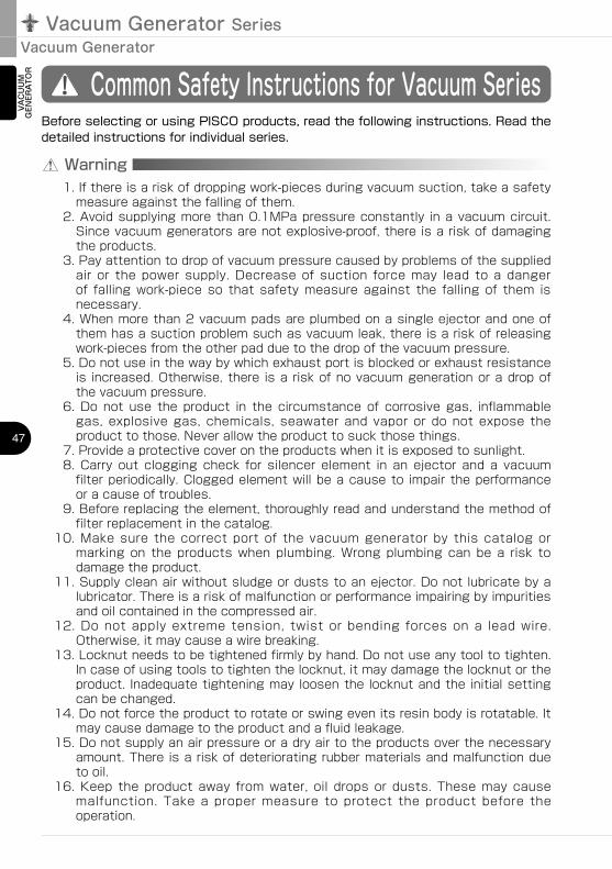
Vacuum Generator SeriesVacuum Generator
47
VAC
UU
M
GEN
ERA
TOR
Common Safety Instructions for Vacuum Series
Warning
Before selecting or using PISCO products, read the following instructions. Read the detailed instructions for individual series.
1. If there is a risk of dropping work-pieces during vacuum suction, take a safety measure against the falling of them.
2. Avoid supplying more than 0.1MPa pressure constantly in a vacuum circuit. Since vacuum generators are not explosive-proof, there is a risk of damaging the products.
3. Pay attention to drop of vacuum pressure caused by problems of the supplied air or the power supply. Decrease of suction force may lead to a danger of falling work-piece so that safety measure against the falling of them is necessary.
4. When more than 2 vacuum pads are plumbed on a single ejector and one of them has a suction problem such as vacuum leak, there is a risk of releasing work-pieces from the other pad due to the drop of the vacuum pressure.
5. Do not use in the way by which exhaust port is blocked or exhaust resistance is increased. Otherwise, there is a risk of no vacuum generation or a drop of the vacuum pressure.
6. Do not use the product in the circumstance of corrosive gas, inflammable gas, explosive gas, chemicals, seawater and vapor or do not expose the product to those. Never allow the product to suck those things.
7. Provide a protective cover on the products when it is exposed to sunlight.8. Carry out clogging check for silencer element in an ejector and a vacuum
filter periodically. Clogged element will be a cause to impair the performance or a cause of troubles.
9. Before replacing the element, thoroughly read and understand the method of filter replacement in the catalog.
10. Make sure the correct port of the vacuum generator by this catalog or marking on the products when plumbing. Wrong plumbing can be a risk to damage the product.
11. Supply clean air without sludge or dusts to an ejector. Do not lubricate by a lubricator. There is a risk of malfunction or performance impairing by impurities and oil contained in the compressed air.
12. Do not apply extreme tension, twist or bending forces on a lead wire. Otherwise, it may cause a wire breaking.
13. Locknut needs to be tightened firmly by hand. Do not use any tool to tighten. In case of using tools to tighten the locknut, it may damage the locknut or the product. Inadequate tightening may loosen the locknut and the initial setting can be changed.
14. Do not force the product to rotate or swing even its resin body is rotatable. It may cause damage to the product and a fluid leakage.
15. Do not supply an air pressure or a dry air to the products over the necessary amount. There is a risk of deteriorating rubber materials and malfunction due to oil.
16. Keep the product away from water, oil drops or dusts. These may cause malfunction. Take a proper measure to protect the product before the operation.
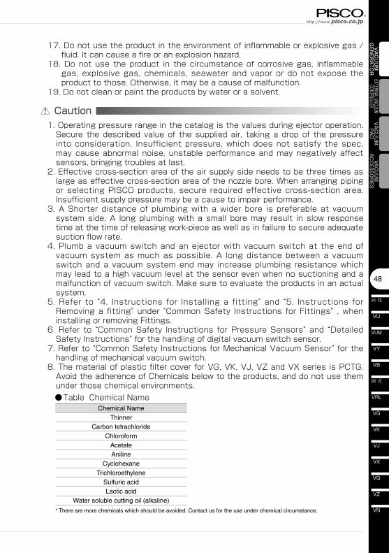
Chemical NameThinner
Carbon tetrachlorideChloroform
AcetateAniline
CyclohexaneTrichloroethylene
Sulfuric acidLactic acid
Water soluble cutting oil (alkaline)
* There are more chemicals which should be avoided. Contact us for the use under chemical circumstance.
48
VN
VZ
VQ
VX
VJ
VK
VG
VM · VC
VB
VU
VH · VS
VY
VUM
VRL
VAC
UU
M
GEN
ERA
TOR
EXTERNAL VACUUM CONTROLLER
VAC
UU
MPA
DVACUUM
ACCESSORIES
Caution1. Operating pressure range in the catalog is the values during ejector operation.
Secure the described value of the supplied air, taking a drop of the pressure into consideration. Insufficient pressure, which does not satisfy the spec, may cause abnormal noise, unstable performance and may negatively affect sensors, bringing troubles at last.
2. Effective cross-section area of the air supply side needs to be three times as large as effective cross-section area of the nozzle bore. When arranging piping or selecting PISCO products, secure required effective cross-section area. Insufficient supply pressure may be a cause to impair performance.
3. A Shorter distance of plumbing with a wider bore is preferable at vacuum system side. A long plumbing with a small bore may result in slow response time at the time of releasing work-piece as well as in failure to secure adequate suction flow rate.
4. Plumb a vacuum switch and an ejector with vacuum switch at the end of vacuum system as much as possible. A long distance between a vacuum switch and a vacuum system end may increase plumbing resistance which may lead to a high vacuum level at the sensor even when no suctioning and a malfunction of vacuum switch. Make sure to evaluate the products in an actual system.
5. Refer to “4. Instructions for Installing a fitting” and “5. Instructions for Removing a fitting” under “Common Safety Instructions for Fittings” , when installing or removing Fittings.
6. Refer to “Common Safety Instructions for Pressure Sensors” and “Detailed Safety Instructions” for the handling of digital vacuum switch sensor.
7. Refer to “Common Safety Instructions for Mechanical Vacuum Sensor” for the handling of mechanical vacuum switch.
8. The material of plastic filter cover for VG, VK, VJ, VZ and VX series is PCTG. Avoid the adherence of Chemicals below to the products, and do not use them under those chemical environments.
●Table Chemical Name
17. Do not use the product in the environment of inflammable or explosive gas / fluid. It can cause a fire or an explosion hazard.
18. Do not use the product in the circumstance of corrosive gas, inflammable gas, explosive gas, chemicals, seawater and vapor or do not expose the product to those. Otherwise, it may be a cause of malfunction.
19. Do not clean or paint the products by water or a solvent.
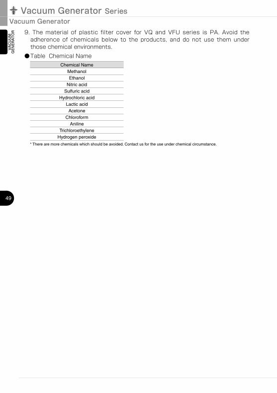
Chemical NameMethanolEthanol
Nitric acidSulfuric acid
Hydrochloric acidLactic acidAcetone
ChloroformAniline
TrichloroethyleneHydrogen peroxide
Vacuum Generator SeriesVacuum Generator
49
VAC
UU
M
GEN
ERA
TOR 9. The material of plastic filter cover for VQ and VFU series is PA. Avoid the
adherence of chemicals below to the products, and do not use them under those chemical environments.
●Table Chemical Name
* There are more chemicals which should be avoided. Contact us for the use under chemical circumstance.
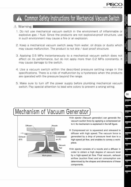
50
VN
VZ
VQ
VX
VJ
VK
VG
VM · VC
VB
VU
VH · VS
VY
VUM
VRL
VAC
UU
M
GEN
ERA
TOR
EXTERNAL VACUUM CONTROLLER
VAC
UU
MPA
DVACUUM
ACCESSORIES
Common Safety Instructions for Mechanical Vacuum Switch Warning
1. Do not use mechanical vacuum switch in the environment of inflammable or explosive gas / fluid. Since the products are not explosive-proof structure, use in such environment may cause a fire or an explosion.
2. Keep a mechanical vacuum switch away from water, oil drops or dusts which may cause malfunction. The product is not drip / dust proof structure.
3. Applying 0.5 MPa instantaneously to a mechanical vacuum switch does not affect on its performance, but do not apply more than 0.2 MPa constantly. It may cause damage to the switch.
4. Use a vacuum switch within the described pressure setting range in the specifications. There is a risk of malfunction by a hysteresis when the products are operated with the pressure beyond the range.
5. Make sure to turn off the power supply before plumbing mechanical vacuum switch. Pay special attention to lead wire colors to prevent a wrong wiring.
Mechanism of Vacuum Generator
Diffuser
Exhaust (EX)
Compressed air (P)
Nozzle
Vacuum Pad
Vacuum (V) (Suction)
Work-piece
●An ejector (Vacuum generator) can generate the vacuum suction force by applying a compressed air to it. Its mechanism is explained in the left figure.
● Compressed air is squeezed and released to diffuser with high speed. The vacuum force is generated by a drop of pressure level due to a high-speed jet flow, and enables to convey a work-piece.
●An ejector consists of a nozzle and a diffuser in order to obtain a high degree of vacuum level by a high-speed jet flow. Final vacuum, exhaust airflow (suction flow) and air consumption are determined by the shapes and dimensions of these components.


![Large flow vacuum filterProduct - PISCO · Flow rate : 360ℓ/min[ANR]. ... Large flow vacuum filter Rotary vacuum pump Dust particles Air supply Dust particles Large flow vacuum](https://img.pdfslide.net/doc/110x75/5eb8e43a186711647c5c0865/large-flow-vacuum-filterproduct-pisco-flow-rate-360aminanr-large-flow.jpg)