Embed Size (px)
Citation preview
KNF 121308-121311 01/15 Translation of original Operating Instructions, english
Operating Instructions Read and observe this Operating Instructions!
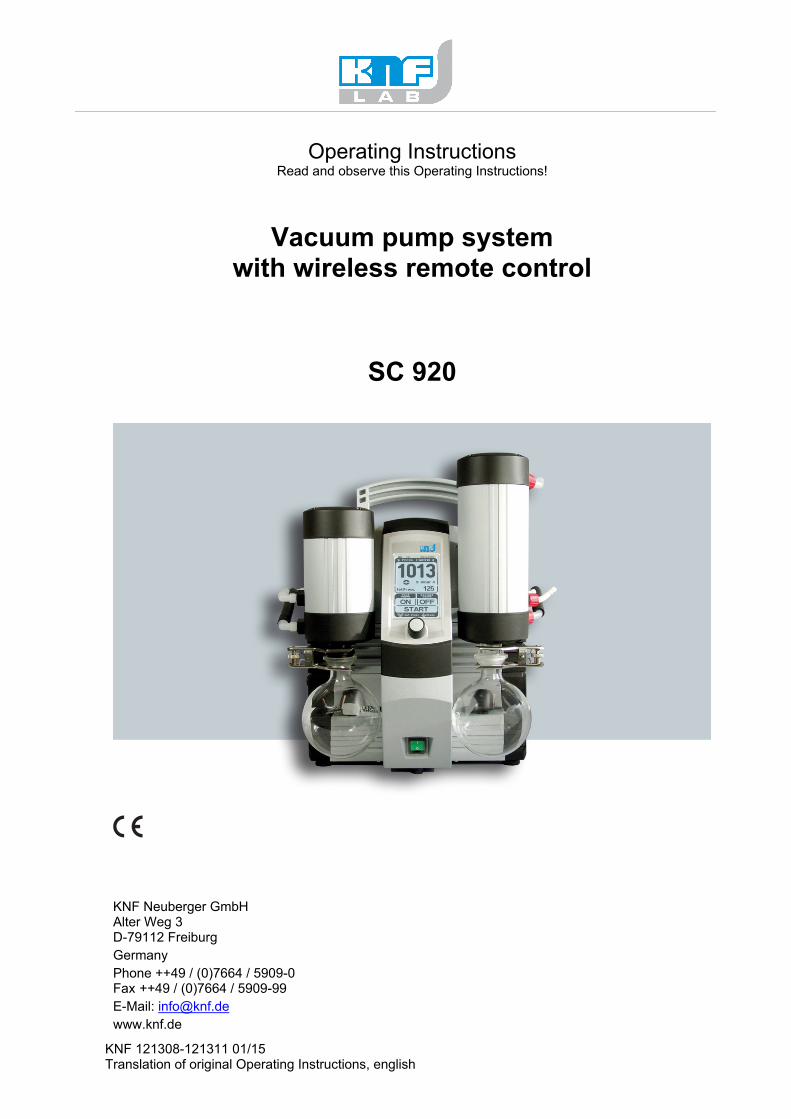
Vacuum pump system with wireless remote control
SC 920
KNF Neuberger GmbH Alter Weg 3 D-79112 Freiburg
Germany
Phone ++49 / (0)7664 / 5909-0 Fax ++49 / (0)7664 / 5909-99
E-Mail: [email protected]
www.knf.de
Translation of original Operating Instructions, english, KNF 121308-121311 01/15
Items including delivery:
� Vacuum pump system including hand terminal (batteries
included)
� Coated collection flasks (2 x)
� Flask clamps (2 x)
� Mains cable
� USB cable for connecting vacuum pump system to PC
� Power supply for hand terminal
� Operating Instructions
� CD with digital Operating Instructions and software for
operating the vacuum pump system with a PC
� Allen key for transport fastener
Transport fastener
The hand terminal is fastened in place at the factory, to prevent
damage during transport.
To remove the hand terminal, it is first necessary to release the
transport fastener. For further details, see chapter
6. Installation and connection.
Vacuum Pump System SC 920 Content
Translation of original Operating Instructions, english, KNF 121308-121311 01/15
Content Page
1. About this document 4
1.1. Using the Operating Instructions 4
1.2. Symbols and Markings 4
2. Use 5
2.1. Proper Use 5
2.2. Improper Use 5
3. Safety 6
4. Technical Data 8
4.1. Vacuum pump system 8
4.2. Vacuum pump system’s hand terminal 9
4.3. Software 10
5. Design and Function 11
5.1. Vacuum pump system overwiew 11
5.2. Vacuum pump system functions 13
5.3. Hand terminal 14
5.4. Pump 15
5.5. Diaphragm stabilization system 16
6. Installation and connection 17
6.1. Installation 17
6.2. Connection 17
7. Operation 19
7.1. Start up 19
7.2. Taking system out of operation 22
8. Operating vacuum pump system 23
8.1. Hand terminal 23
8.1.1. General functions and displays 23
8.1.2. Operation 25
8.1.3. Changing batteries on the hand terminal 29
8.2. Operation without hand terminal 30
8.3. Software 31
8.3.1. General functions and displays 31
8.3.2. Operation 32
9. Servicing 37
9.1. Servicing Schedule 37
9.2. Cleaning 37
9.2.1. Flushing Vacuum pump system 37
9.2.2. Cleaning Vacuum pump system 37
9.2.3. Emptying collection flask on the suction and pressure sides 37
9.3. Changing Diaphragms and Valve Plates 38
9.4. Replace overpressure valve on high performance condenser 42
10. Troubleshooting 43
11. Ordering Information 48
12. Returns 49
13. Health and safety clearance and decontamination form 50
14. Annex: Interface protocol 51
About this document Vacuum Pump System SC 920
4 Translation of original Operating Instructions, English, KNF 121308-121311 01/15
1. About this document
1.1. Using the Operating Instructions
The Operating Instructions are part of the vacuum pump system.
� Carefully study the Operating Instructions before using a
vacuum pump system.
� Always keep the Operating Instructions handy in the work area.
� Pass on the Operating Instructions to the next owner.
Customer-specific project systems (systems which begin with “PJ”
or “PM”) may differ from the Operating Instructions.
� For project systems, also observe the agreed upon
specifications.
Compliance with the Operating Instructions is essential for the
safe and reliable operation of the vacuum pump system.
Failure to do so may result in damage or injury.
1.2. Symbols and Markings
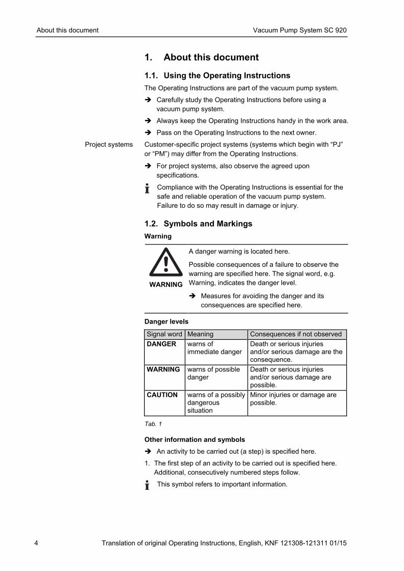
Warning
WARNING
A danger warning is located here. Possible consequences of a failure to observe the
warning are specified here. The signal word, e.g.
Warning, indicates the danger level. � Measures for avoiding the danger and its
consequences are specified here.
Danger levels
Signal word Meaning Consequences if not observed
DANGER warns of immediate danger
Death or serious injuries and/or serious damage are the consequence.
WARNING warns of possible danger
Death or serious injuries and/or serious damage are possible.
CAUTION warns of a possibly dangerous situation
Minor injuries or damage are possible.
Tab. 1
Other information and symbols
� An activity to be carried out (a step) is specified here.
1. The first step of an activity to be carried out is specified here.
Additional, consecutively numbered steps follow.
This symbol refers to important information.
Project systems
Vacuum Pump System SC 920 Use
Translation of original Operating Instructions, English, KNF 121308-121311 01/15 5
2. Use
2.1. Proper Use
The SC 920 vacuum pump system is designed for use in chemical,
pharmaceutical, and biological laboratories. The vacuum pump
system is exclusively intended for transferring gases and vapors.
Make sure that the installation location is dry and the pump/system
is protected against rain, splash, hose and drip water.
Vacuum pump system is solely for use in indoor areas.
Owner's responsibility
Only install and operate the vacuum pump system under the
operating parameters and conditions described in chapter 4,
Technical data.
Protect vacuum pump system against humidity.
Before using a medium, check the compatibility of the materials of
the pump head, diaphragm, stabilization diaphragm, valves,
sealings and tubing with the medium.
Before using a medium, check whether the medium can be trans-
ferred danger-free in the specific application case.
Only transfer gases which remain stable under the pressures and
temperatures occurring in the pump.
The high performance condenser must be installed on the outlet
side of the pump; if it is installed on the inlet side there is a danger
of implosion.
Observe the correct usage of the gas- and cooling liquid-
connections on the high performance condenser. Inlet and outlet
connections for the gas are not interchangeable.
Laboratory equipment or additional components connected to a
vacuum pump system have to be suitable for use with the pneu-
matic capabilities of the vacuum pump system (see chapter 4,
page 8).
2.2. Improper Use
The vacuum pump system may not be operated in an explosive
atmosphere.
The vacuum pump system is not suitable for transferring dusts.
The vacuum pump system is not suitable for transferring liquids.
The vacuum pump system must not be used if the entry of air or
gas into the vacuum pump system during venting (vent valve)
could result in the creation of reactive, explosive or otherwise
hazardous mixtures (e.g. with the medium).
The vacuum pump system must not be used to create vacuum and
overpressure simultaneously.
An overpressure must not be applied to the suction side of the
vacuum pump system.
Operating parameters and
conditions
Requirements for
transferred medium
High performance condenser
Accessories
Safety Vacuum Pump System SC 920
6 Translation of original Operating Instructions, English, KNF 121308-121311 01/15
3. Safety
The vacuum pump system is built according to the generally recog-
nized rules of technology and in accordance with the occupational
safety and accident prevention regulations. Nevertheless, dangers
can result during their use which lead to injuries to the user or
others, or to damage to the vacuum pump system or other property.
Only use the vacuum pump system when it is in a good technical
and proper working order, in accordance with its intended use,
observing the safety advice within the operating instructions, at all
times.
Make sure that only trained and instructed personnel or specially
trained personnel work on the vacuum pump system. This
especially applies to assembly, connection and servicing work.
Make sure that the personnel has read and understood the opera-
ting instructions, and in particular the "Safety" chapter.
Observe the accident prevention and safety regulations when per-
forming any work on the vacuum pump system and during opera-
tion.
Do not expose any part of your body to the vacuum.
Open housing parts with notice sticker (see fig. 1) only after sepa-
rating mains plug from power source.
Ensure that the employees check that the hand terminal is the right
one for this particular system before using a SC 920 vacuum pump
system. Vacuum pump systems are equipped with a paging sys-
tem for this purpose (see Actuating the vacuum pump system,
page 28).
When transferring dangerous media, observe the safety regula-
tions when handling these media.
Be aware that the vacuum pump system is not designed to be
explosion-proof.
Make sure the temperature of the medium is always sufficiently
below the ignition temperature of the medium, to avoid ignition or
explosion. This also applies for unusual operational situations.
Note that the temperature of the medium increases when the pump
compresses the medium.
Hence, make sure the temperature of the medium is sufficiently
below the ignition temperature of the medium, even when it is
compressed to the maximum permissible operating pressure of the
vacuum pump system. The maximum permissible operating pres-
sure of the vacuum pump system is stated in the technical speci-
fications (see chapter 4, page 8).
If necessary, consider any external sources of energy, such as
radiation, that may add heat to the medium.
In case of doubt, consult the KNF customer service.
Personnel
Working in a safety-
conscious manner
Fig. 1: Notice sticker
Correct match between hand
terminal and vacuum pump
system
Handling dangerous media
Handling flammable media
Vacuum Pump System SC 920 Safety
Translation of original Operating Instructions, English, KNF 121308-121311 01/15 7
When ventilating the vacuum pump system with air or inert gas, be
sure to prevent formation of reactive or explosive media. The
maximum permissible operating pressure at the ventilation
connection (Fig 2/5, page 11) is 0.1 bar g.
Store all replacement parts in a protected manner and dispose of
them properly in accordance with the applicable environmental
protection regulations. Observe the respective national and inter-
national regulations. This especially applies to parts contaminated
with toxic substances.
The vacuum pump system SC 920 conforms to the Directive
2011/65/EU (RoHS2).
The vacuum pump system SC 920 conforms to the safety
regulations of the EC Directive 2004/108/EC concerning
Electromagnetic Compatibility and the EC Directive 2006/42/EC
concerning Machinery. The requirements of the following
harmonised standards are fulfilled:
� DIN EN 61010-1
� DIN EN 55011 – class A
� DIN EN 61326-1
� DIN EN 61000-3-2/3
The pumps correspond to IEC 664:
� the overvoltage category II
� the pollution degree 2
Only have repairs to the vacuum pump system carried out by the
KNF Customer Service responsible.
Only authorized personnel should open those parts of the housing
that contain live electrical parts.
Use only genuine parts from KNF for servicing work.
Ventilating the vacuum pump
system
Environmental protection
Standards
Customer service and
repairs
Technical Data Vacuum Pump System SC 920
8 Translation of original Operating Instructions, English, KNF 121308-121311 01/15
4. Technical Data
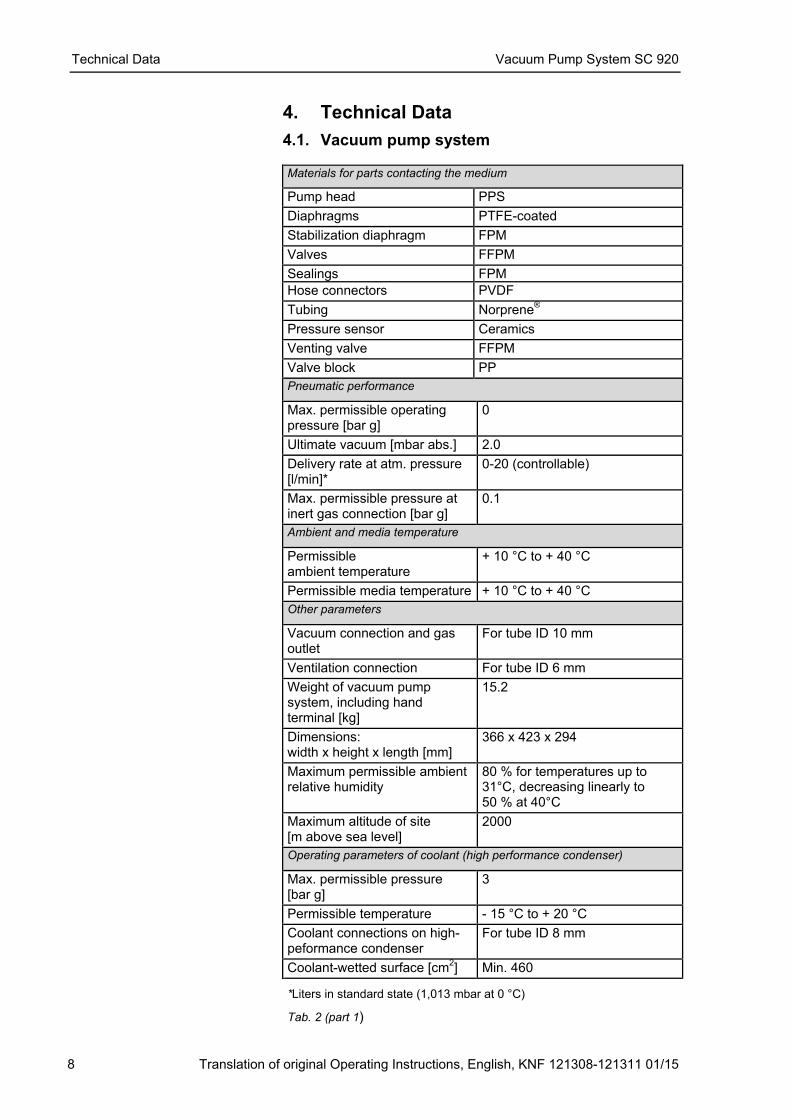
4.1. Vacuum pump system Materials for parts contacting the medium
Pump head PPS
Diaphragms PTFE-coated
Stabilization diaphragm FPM
Valves FFPM
Sealings FPM
Hose connectors PVDF
Tubing Norprene®
Pressure sensor Ceramics
Venting valve FFPM
Valve block PP
Pneumatic performance
Max. permissible operating pressure [bar g]
0
Ultimate vacuum [mbar abs.] 2.0
Delivery rate at atm. pressure [l/min]*
0-20 (controllable)
Max. permissible pressure at inert gas connection [bar g]
0.1
Ambient and media temperature
Permissible ambient temperature
+ 10 °C to + 40 °C
Permissible media temperature + 10 °C to + 40 °C
Other parameters
Vacuum connection and gas outlet
For tube ID 10 mm
Ventilation connection For tube ID 6 mm
Weight of vacuum pump system, including hand terminal [kg]
15.2
Dimensions: width x height x length [mm]
366 x 423 x 294
Maximum permissible ambient relative humidity
80 % for temperatures up to 31°C, decreasing linearly to 50 % at 40°C
Maximum altitude of site [m above sea level]
2000
Operating parameters of coolant (high performance condenser)
Max. permissible pressure [bar g]
3
Permissible temperature - 15 °C to + 20 °C
Coolant connections on high-peformance condenser
For tube ID 8 mm
Coolant-wetted surface [cm2] Min. 460
*Liters in standard state (1,013 mbar at 0 °C)
Tab. 2 (part 1)
Vacuum Pump System SC 920 Technical Data
Translation of original Operating Instructions, English, KNF 121308-121311 01/15 9
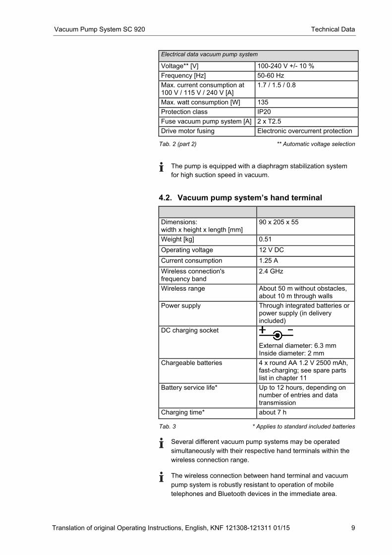
Electrical data vacuum pump system
Voltage** [V] 100-240 V +/- 10 %
Frequency [Hz] 50-60 Hz
Max. current consumption at 100 V / 115 V / 240 V [A]
1.7 / 1.5 / 0.8
Max. watt consumption [W] 135
Protection class IP20
Fuse vacuum pump system [A] 2 x T2.5
Drive motor fusing Electronic overcurrent protection Tab. 2 (part 2) ** Automatic voltage selection
The pump is equipped with a diaphragm stabilization system
for high suction speed in vacuum.
4.2. Vacuum pump system’s hand terminal
Dimensions: width x height x length [mm]
90 x 205 x 55
Weight [kg] 0.51
Operating voltage 12 V DC
Current consumption 1.25 A
Wireless connection's frequency band
2.4 GHz
Wireless range About 50 m without obstacles, about 10 m through walls
Power supply Through integrated batteries or power supply (in delivery included)
DC charging socket
External diameter: 6.3 mm Inside diameter: 2 mm
Chargeable batteries 4 x round AA 1.2 V 2500 mAh, fast-charging; see spare parts list in chapter 11
Battery service life* Up to 12 hours, depending on number of entries and data transmission
Charging time* about 7 h Tab. 3 * Applies to standard included batteries
Several different vacuum pump systems may be operated
simultaneously with their respective hand terminals within the
wireless connection range.
The wireless connection between hand terminal and vacuum
pump system is robustly resistant to operation of mobile
telephones and Bluetooth devices in the immediate area.
Technical Data Vacuum Pump System SC 920
10 Translation of original Operating Instructions, English, KNF 121308-121311 01/15
4.3. Software
System requirements for operating the vacuum pump system via
PC software:
� Windows 98 SE, Windows ME, Windows NT, Windows 2000,
Windows XP, Windows 7
� 200 MHz processor
� Available memory of at least 64 MB
The USB connection between the PC and vacuum pump system is
operated as an RS-232 interface. Accordingly, in the operating
system it is managed as an additional COM connection and can be
addressed with conventional terminal software. The interface pro-
tocol contains all necessary information. See chapter 14, page 51.
Vacuum Pump System SC 920 Design and Function
Translation of original Operating Instructions, English, KNF 121308-121311 01/15 11
5. Design and Function
5.1. Vacuum pump system overwiew
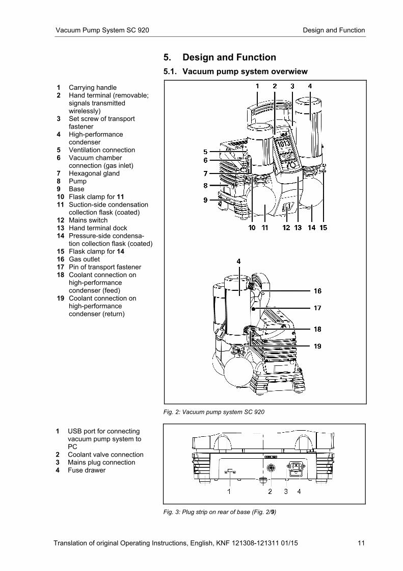
1 Carrying handle 2 Hand terminal (removable;
signals transmitted wirelessly)
3 Set screw of transport fastener
4 High-performance condenser
5 Ventilation connection 6 Vacuum chamber
connection (gas inlet) 7 Hexagonal gland 8 Pump 9 Base 10 Flask clamp for 11 11 Suction-side condensation
collection flask (coated) 12 Mains switch 13 Hand terminal dock 14 Pressure-side condensa-
tion collection flask (coated) 15 Flask clamp for 14 16 Gas outlet 17 Pin of transport fastener 18 Coolant connection on
high-performance condenser (feed)
19 Coolant connection on high-performance condenser (return)
Fig. 2: Vacuum pump system SC 920
1 USB port for connecting vacuum pump system to PC
2 Coolant valve connection 3 Mains plug connection 4 Fuse drawer
Fig. 3: Plug strip on rear of base (Fig. 2/9)
Design and Function Vacuum Pump System SC 920
12 Translation of original Operating Instructions, English, KNF 121308-121311 01/15
The vacuum pump system generates a vacuum that can be con-
trolled either through the hand terminal (see chapter 5.3, page 14)
or a PC.
Collection flask (Fig. 2/11) collects on the suction side of the pump
particles and drops that were, contrary to the requirements of the
pump, suctioned from the vacuum chamber. The collection flask is
coated (implosion protection) and fastened to the vacuum pump
system via a flask clip.
The high-performance condenser at the pump outlet once again
recollects solvents from the pumped gas instead of allowing it exit
into the environment or fume hood. The high-performance con-
denser is surrounded by a shell for temperature insulation and
explosion protection.
Solvents deposited in the high-performance condenser are col-
lected in the coated (for explosion protection) collection flask (Fig.
2/14). A flask clip secures the glass flask to the condenser flange.
A recirculating cooler or continuously flowing cold water cools the
high-performance condenser to the condensation temperature.
Vacuum Pump System SC 920 Design and Function
Translation of original Operating Instructions, English, KNF 121308-121311 01/15 13
5.2. Vacuum pump system functions
The vacuum pump system can be operated in four different modes:
� Evacuate
The vacuum pump system evacuates a vacuum chamber with
adjustable pump capacity.
� Pressure control
The vacuum pump system controls system pressure to the set-
point pressure value (constant pressure).
� Automatic
The vacuum pump system independently finds the sample's
vapor pressure and adjusts process pressure accordingly.
� Function
The vacuum pump system controls pressure according to the
entered pressure curve. The following process parameters can
be entered:
− Setpoint pressure at various time points after starting the
process
− Coolant valve (accessory) ON and OFF with time point
after start of process
At any time during an active process, you can switch to manual
process control. Functions for Evacuate and Pressure control will
be available simultaneously. When activating manual process con-
trol, the current actual pressure will be adopted as the first setpoint
pressure. In other words, process pressure will be initially "frozen"
at the current value.
The operating modes can be combined in any way for the pur-
poses of intelligent process control. For example, after successful
boiling point detection in the automatic mode, the following opera-
ting modes are available for specific distilling off of the solvent
recovered:
� Evacuation
(constant vaporization rate for optimum condenser capacity
utilization)
� Function
(Following a preset pressure ramp provided in order to attain a
separation from components with higher boiling points)
� Manual process control
(active control of the distillation using the setpoint pressure)
In order to change to another operating mode, the process is first
stopped and then restarted in the new operating mode.
Design and Function Vacuum Pump System SC 920
14 Translation of original Operating Instructions, English, KNF 121308-121311 01/15
5.3. Hand terminal
Basic elements
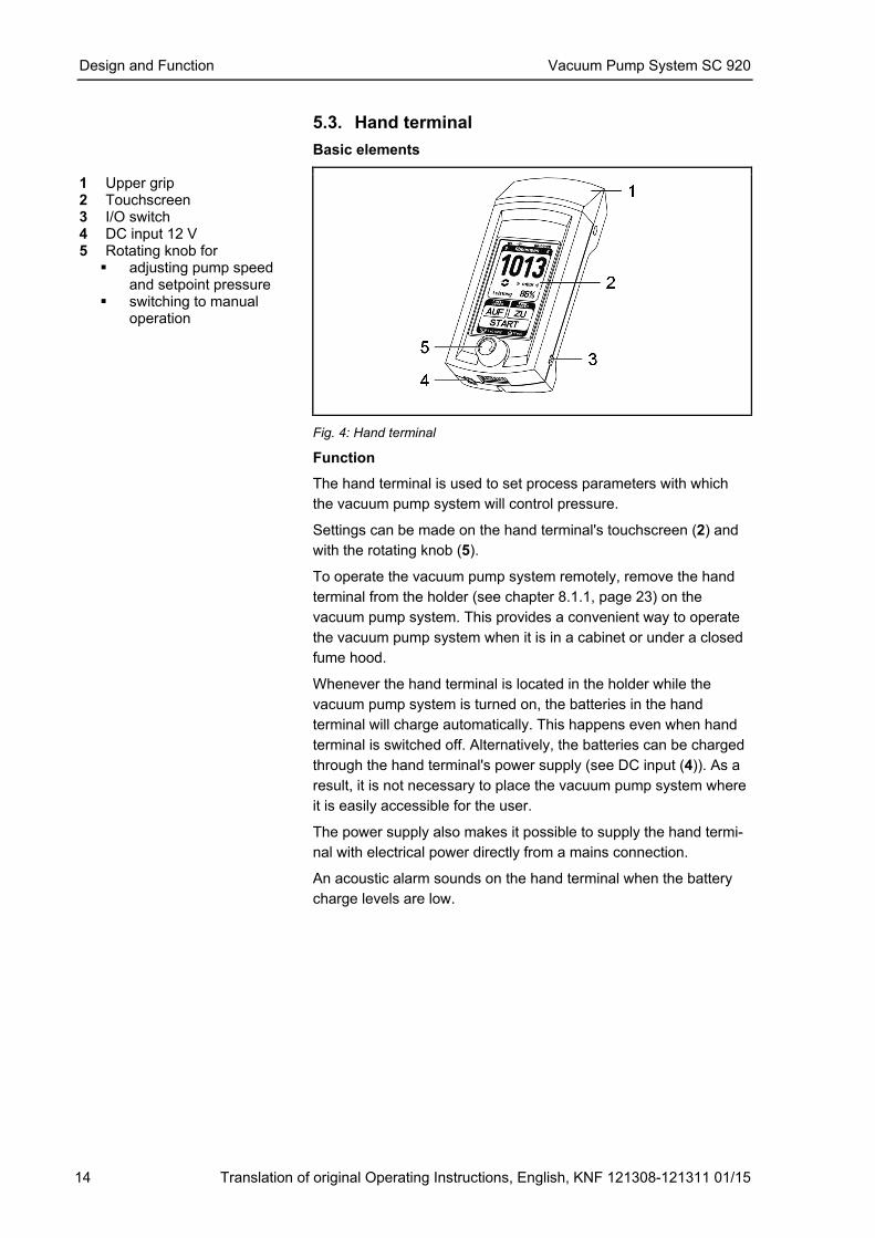
1 Upper grip 2 Touchscreen 3 I/O switch 4 DC input 12 V 5 Rotating knob for
� adjusting pump speed and setpoint pressure
� switching to manual operation
Fig. 4: Hand terminal
Function
The hand terminal is used to set process parameters with which
the vacuum pump system will control pressure.
Settings can be made on the hand terminal's touchscreen (2) and
with the rotating knob (5).
To operate the vacuum pump system remotely, remove the hand
terminal from the holder (see chapter 8.1.1, page 23) on the
vacuum pump system. This provides a convenient way to operate
the vacuum pump system when it is in a cabinet or under a closed
fume hood.
Whenever the hand terminal is located in the holder while the
vacuum pump system is turned on, the batteries in the hand
terminal will charge automatically. This happens even when hand
terminal is switched off. Alternatively, the batteries can be charged
through the hand terminal's power supply (see DC input (4)). As a
result, it is not necessary to place the vacuum pump system where
it is easily accessible for the user.
The power supply also makes it possible to supply the hand termi-
nal with electrical power directly from a mains connection.
An acoustic alarm sounds on the hand terminal when the battery
charge levels are low.
Vacuum Pump System SC 920 Design and Function
Translation of original Operating Instructions, English, KNF 121308-121311 01/15 15
5.4. Pump
Design
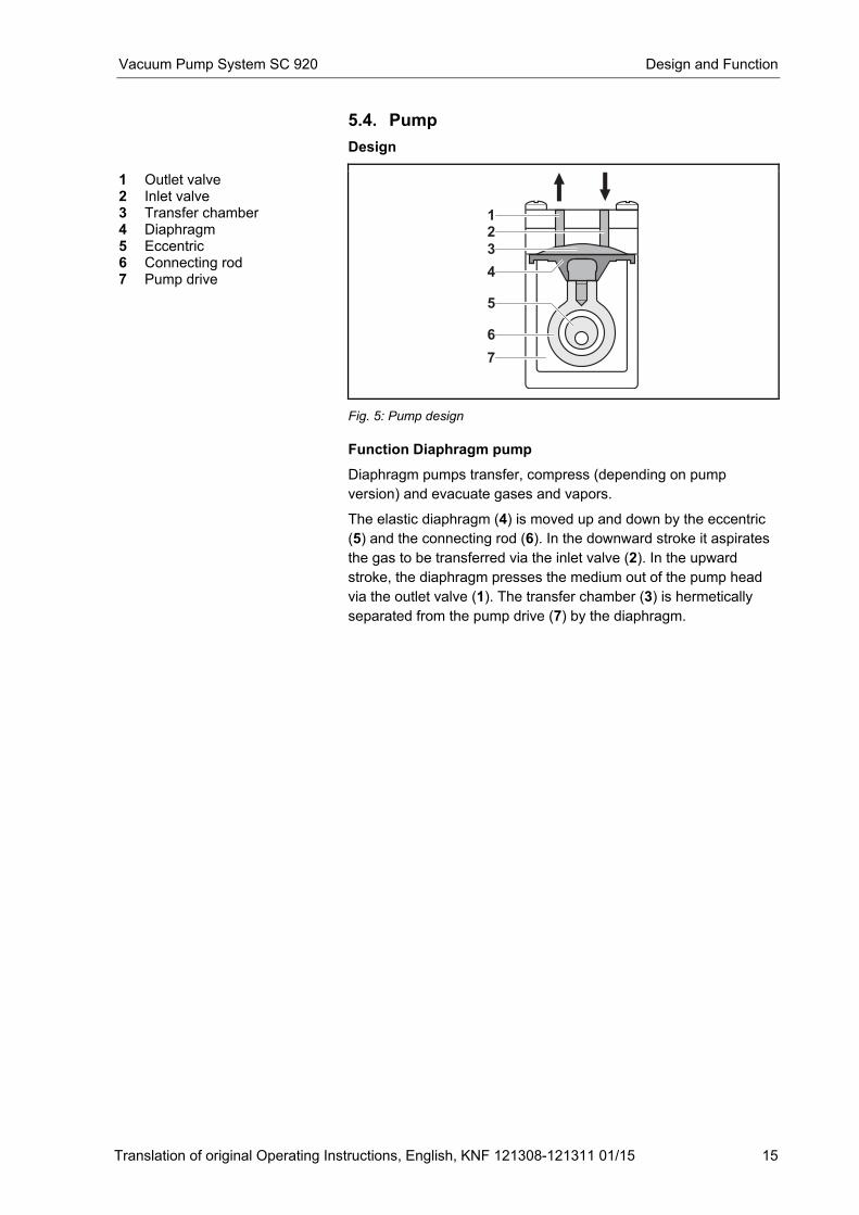
1 Outlet valve 2 Inlet valve 3 Transfer chamber 4 Diaphragm 5 Eccentric 6 Connecting rod 7 Pump drive
Fig. 5: Pump design
Function Diaphragm pump
Diaphragm pumps transfer, compress (depending on pump
version) and evacuate gases and vapors.
The elastic diaphragm (4) is moved up and down by the eccentric
(5) and the connecting rod (6). In the downward stroke it aspirates
the gas to be transferred via the inlet valve (2). In the upward
stroke, the diaphragm presses the medium out of the pump head
via the outlet valve (1). The transfer chamber (3) is hermetically
separated from the pump drive (7) by the diaphragm.
Design and Function Vacuum Pump System SC 920
16 Translation of original Operating Instructions, English, KNF 121308-121311 01/15
5.5. Diaphragm stabilization system
Design
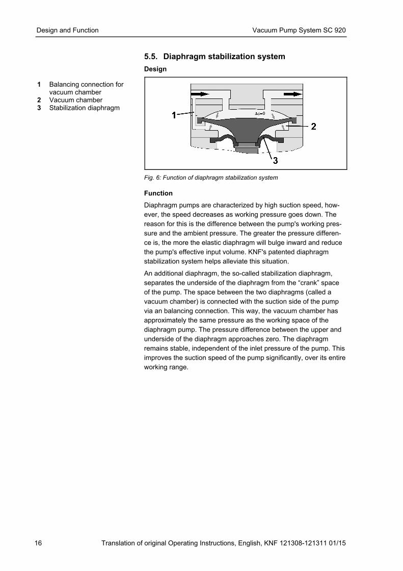
1 Balancing connection for vacuum chamber
2 Vacuum chamber 3 Stabilization diaphragm
Fig. 6: Function of diaphragm stabilization system
Function
Diaphragm pumps are characterized by high suction speed, how-
ever, the speed decreases as working pressure goes down. The
reason for this is the difference between the pump's working pres-
sure and the ambient pressure. The greater the pressure differen-
ce is, the more the elastic diaphragm will bulge inward and reduce
the pump's effective input volume. KNF's patented diaphragm
stabilization system helps alleviate this situation.
An additional diaphragm, the so-called stabilization diaphragm,
separates the underside of the diaphragm from the “crank” space
of the pump. The space between the two diaphragms (called a
vacuum chamber) is connected with the suction side of the pump
via an balancing connection. This way, the vacuum chamber has
approximately the same pressure as the working space of the
diaphragm pump. The pressure difference between the upper and
underside of the diaphragm approaches zero. The diaphragm
remains stable, independent of the inlet pressure of the pump. This
improves the suction speed of the pump significantly, over its entire
working range.
Vacuum Pump System SC 920 Installation and connection
Translation of original Operating Instructions, English, KNF 121308-121311 01/15 17
6. Installation and connection
� Only install the vacuum pump system under the operating
parameters and conditions described in chapter 4, Technical
data, page 8).
� Observe the safety precautions (see chapter 3, page 6).
6.1. Installation
� Before installation, store the vacuum pump system at the
installation location to bring it up to room temperature.
� Install the vacuum pump system so that the motor fan of the
pump can intake sufficient cooling air.
� Make sure that the installation location is dry and the vacuum
pump system is protected against rain, splash, hose and drip
water.
� Choose a safe location (flat surface) for the vacuum pump
system.
� Protect the vacuum pump system from dust.
� Protect the vacuum pump system from vibrations and jolts.
� Only connect components to the vacuum pump system which
are designed for the pneumatic data of the vacuum pump sys-
tem (see chapter 4, page 8).
A recirculating cooler or flowing cold water is needed to cool the
high-performance condenser to the condensation temperature.
� The hand terminal is fastened in place at the factory, to prevent
damage during transport. To remove the hand terminal, it is
first necessary to release the transport fastener.
1. Loosen the set screw (Fig. 2/3, p. 11).
2. Pull out the pin of the transport fastener (Fig. 2/17, p. 11) as far
as the limit stop.
3. Tighten the set screw again.
The transport fastener can be reattached for any future
transport operations.
6.2. Connection
1. Connect the vacuum chamber to the gas inlet's hose connec-
tor (Fig. 2/6, page 11, for hose inside diameter of 10 mm). For
this, vacuum tubing must be used.
2. Connect hose to high-performance condenser in order to
discharge gas exhaust (Fig. 2/16, page 11, for hose inside
diameter of 10 mm).
CAUTION
Danger of high performance condenser bursting.
The high-performance condenser is not pressure-
proof. � Do not reduce or regulate the quantity of gas at
the gas outlet, and do not install any compo-
nents that hinder the gas flow.
Cooling air supply
Installation location
Connected components
Coolant for high-performance
condenser
Removing the transport
fastener
Installation and connection Vacuum Pump System SC 920
18 Translation of original Operating Instructions, English, KNF 121308-121311 01/15
Safely discharge gas exhaust so that no gas can escape into
the ambient air.
Make sure that the high-performance condenser’s gas outlet is
not blocked (high-performance condenser is not pressure-
proof). 3. Attach coolant feed and return to high-performance condenser
(Fig. 2/18 and 19, page 11, for hose inside diameter of 8 mm).
4. If necessary: Connect inert gas supply to ventilation connec-
tion (Fig. 2/5, page 11). Observe the safety instructions in
chapter 3.
5. Insert the power cable plug into a properly installed shockproof
socket.
Vacuum Pump System SC 920 Operation
Translation of original Operating Instructions, English, KNF 121308-121311 01/15 19
7. Operation
7.1. Start up Before switching on the vacuum pump system, observe the
following points:
Operational requirements
� All hoses attached properly
� Fan openings not blocked
� Specifications of the power supply correspond with the data
on the vacuum pump system’s type plate.
� Recirculating cooler or cold water connection ready on high-
performance condenser.
� The high-performance condenser's gas outlet is not blocked
(high-performance condenser is not pressure-proof).
� Vacuum pump system is at room temperature.
� Vacuum pump system and hand terminal belong together.
� No reactive, explosive or otherwise hazardous mixtures may
be produced when ventilating the vacuum system through the
air inlet (Fig. 2/5, page 11) (if necessary, use an inert gas)
Tab. 4
� Only operate the vacuum pump system under the operating
parameters and conditions described in chapter 4, Technical
data (page 8).
� Make sure the vacuum pump system is used properly (see
chapter 2.1, page 5).
� Make sure the vacuum pump system is not used improperly
(see chapter 2.2, page 5).
� Observe the safety precautions (see chapter 3, page 6).
Operation Vacuum Pump System SC 920
20 Translation of original Operating Instructions, English, KNF 121308-121311 01/15
DANGER
Uncontrolled operation may result in personal injury
and damage to the vacuum pump system. When using several vacuum pump systems, there is
the danger of confusing them, which can result in
undesired interference into other processes: The
transmission of commands from the wrong hand
terminal for the vacuum pump system may trigger an
uncontrolled response in the vacuum pump system
that the terminal controls. � Every time a vacuum pump system is used with
a hand terminal, it is essential to ensure a
correct match between the two components. Use
the paging function for this purpose (see
Actuating the vaccum pump system, page 28).
� Additionally it is possible to use color stickers to
indicate which hand terminal belongs to which
vacuum pump system (see chapter 11. Ordering
information).
WARNING
Uncontrolled operation may result in personal injury
and damage to the vacuum pump system. If the wireless connection between the hand terminal
and vacuum pump system is broken, the vacuum
pump system will continue to operate with the cur-
rent settings. � Immediately determine and remove the cause of
the interruption between the hand terminal and
vacuum pump system (chapter 10, page 43).
� If you are not able to reestablish wireless
contact, replace the hand terminal back to the
vacuum pump system (chapter 8.1.1, page 23).
The vacuum pump system can also be operated
directly and the ventilation valve and coolant
valve can be opened and closed directly
(chapter 8.2, page 30).
WARNING
Personal injury caused by poisoning or explosion
and damage to the vacuum pump system. � Make sure that no reactive or explosive mixtures
will be produced when ventilating the vacuum
pump system through the air inlet.
Vacuum Pump System SC 920 Operation
Translation of original Operating Instructions, English, KNF 121308-121311 01/15 21
WARNING
Hazard of the vacuum pump system bursting due to
excessive pressure increase � Do not exceed max. permissible operating
pressure (0 bar).
� Monitor pressure during operation.
� If the pressure exceeds the maximum permis-
sible operating pressure, immediately shut down
vacuum pump system and eliminate fault (see
chapter 10, page 43).
WARNING
Personal injury caused by poisoning or explosion
and damage to the pump. � Make sure that no reactive or explosive mixtures
will be produced when ventilating the vacuum
system through the air inlet.
� Make sure that the media are compatible with
each other (when running two different
processes simultaneously).
CAUTION
Danger of high performance condenser bursting.
The high-performance condenser is not pressure-
proof. � Make sure that the high performance
condenser’s gas outlet is not blocked.
In order for the high-performance condenser to recover solvent
from the delivered gas, it must be cooled by means of a cold
water supply or recirculating cooler. When using a coolant valve:
WARNING
Danger of the high performance condenser bursting � Make sure that the coolant valve is mounted
between the coolant supply and the coolant inlet
port of high performance condenser.
With the pump at a standstill, open pressure and suction lines to
normal atmospheric pressure
At appropriate intervals, inspect the fill level in the condensation
collection flasks located on the suction and pressure sides of the
vacuum pump system (Fig. 2/11 and 14, page 11). When needed,
empty the collection flasks; properly dispose contents.
Switching vacuum pump system on
The vacuum pump system may not start up against overpres-
sure during switch-on. During operation as well, there may be
no overpressure in the pneumatic lines. If a pump starts against
pressure, it may block. This activates the thermal switch, and
the pump switches off.
Pump standstill
Inspect and empty collection
flasks
Operation Vacuum Pump System SC 920
22 Translation of original Operating Instructions, English, KNF 121308-121311 01/15
� Switch on vacuum pump system at mains switch (Fig. 2/12,
page 11).
� Switch on hand terminal at its I/O switch (see Fig. 4/3, page
14).
Refer to chapter 8, page 23, for information on operating the
vacuum pump system.
7.2. Taking system out of operation
� Stop the ongoing process.
� When transferring aggressive media, flush the vacuum pump
system prior to switch-off to increase the service life of the
diaphragms (see chapter 9.2.1, page 37).
� Switch off vacuum pump system with mains switch (see fig. Fig.
2/12, page 11).
� Switch off hand terminal at its I/O switch (see Fig. 4/3, page
14).
WARNING
Uncontrolled operation may result in personal injury
and damage to the vacuum pump system.
If the hand terminal is switched off while the vacuum
pump system remains switched on, the vacuum
pump system will continue to operate with the cur-
rent settings. � Always switch the vacuum pump system off
when done working.
Vacuum Pump System SC 920 Operating vacuum pump system
Translation of original Operating Instructions, English, KNF 121308-121311 01/15 23
8. Operating vacuum pump system
8.1. Hand terminal
8.1.1. General functions and displays
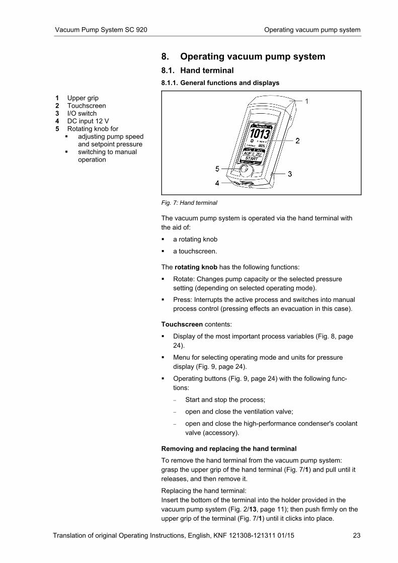
1 Upper grip 2 Touchscreen 3 I/O switch 4 DC input 12 V 5 Rotating knob for
� adjusting pump speed and setpoint pressure
� switching to manual operation
Fig. 7: Hand terminal
The vacuum pump system is operated via the hand terminal with
the aid of:
� a rotating knob
� a touchscreen.
The rotating knob has the following functions:
� Rotate: Changes pump capacity or the selected pressure
setting (depending on selected operating mode).
� Press: Interrupts the active process and switches into manual
process control (pressing effects an evacuation in this case).
Touchscreen contents:
� Display of the most important process variables (Fig. 8, page
24).
� Menu for selecting operating mode and units for pressure
display (Fig. 9, page 24).
� Operating buttons (Fig. 9, page 24) with the following func-
tions:
− Start and stop the process;
− open and close the ventilation valve;
− open and close the high-performance condenser's coolant
valve (accessory).
Removing and replacing the hand terminal
To remove the hand terminal from the vacuum pump system:
grasp the upper grip of the hand terminal (Fig. 7/1) and pull until it
releases, and then remove it.
Replacing the hand terminal:
Insert the bottom of the terminal into the holder provided in the
vacuum pump system (Fig. 2/13, page 11); then push firmly on the
upper grip of the terminal (Fig. 7/1) until it clicks into place.
Operating vacuum pump system Vacuum Pump System SC 920
24 Translation of original Operating Instructions, English, KNF 121308-121311 01/15
Whenever the hand terminal is located in the holder while the
vacuum pump system is turned on, the batteries in the hand
terminal will charge automatically. This happens irrespective of
whether the hand terminal is switched on or off.
Every time you use a hand terminal, check to ensure a correct
match between the terminal and the vacuum pump system.
Use the paging system for this purpose (see Actuating the
vacuum pump system, page 28).
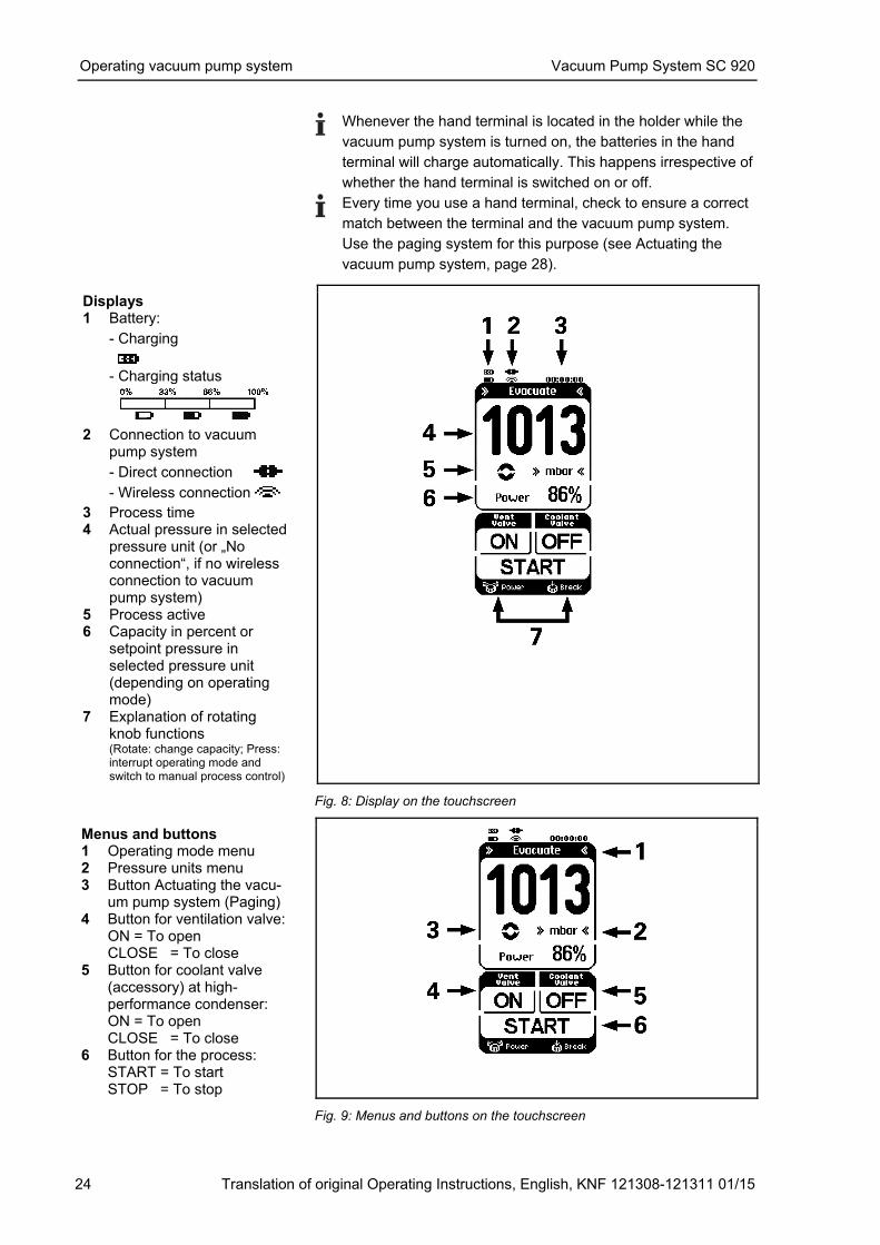
Displays 1 Battery:
- Charging
- Charging status
2 Connection to vacuum
pump system
- Direct connection
- Wireless connection
3 Process time 4 Actual pressure in selected
pressure unit (or „No connection“, if no wireless connection to vacuum pump system)
5 Process active 6 Capacity in percent or
setpoint pressure in selected pressure unit (depending on operating mode)
7 Explanation of rotating knob functions (Rotate: change capacity; Press: interrupt operating mode and switch to manual process control)
Fig. 8: Display on the touchscreen
Menus and buttons 1 Operating mode menu 2 Pressure units menu 3 Button Actuating the vacu-
um pump system (Paging) 4 Button for ventilation valve:
ON = To open CLOSE = To close
5 Button for coolant valve (accessory) at high-performance condenser: ON = To open CLOSE = To close
6 Button for the process: START = To start STOP = To stop
Fig. 9: Menus and buttons on the touchscreen
Vacuum Pump System SC 920 Operating vacuum pump system
Translation of original Operating Instructions, English, KNF 121308-121311 01/15 25
8.1.2. Operation
Menu language
When the start page appears after switching the hand terminal on,
choose between the following languages: English, German, French,
Italian, Spanish and Chinese. The selection can be made only
immediately after switching on.
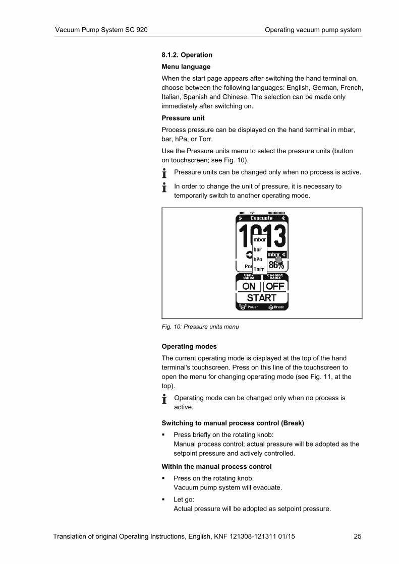
Pressure unit
Process pressure can be displayed on the hand terminal in mbar,
bar, hPa, or Torr.
Use the Pressure units menu to select the pressure units (button
on touchscreen; see Fig. 10).
Pressure units can be changed only when no process is active.
In order to change the unit of pressure, it is necessary to
temporarily switch to another operating mode.
Fig. 10: Pressure units menu
Operating modes
The current operating mode is displayed at the top of the hand
terminal's touchscreen. Press on this line of the touchscreen to
open the menu for changing operating mode (see Fig. 11, at the
top).
Operating mode can be changed only when no process is
active.
Switching to manual process control (Break)
� Press briefly on the rotating knob:
Manual process control; actual pressure will be adopted as the
setpoint pressure and actively controlled.
Within the manual process control
� Press on the rotating knob:
Vacuum pump system will evacuate.
� Let go:
Actual pressure will be adopted as setpoint pressure.
Operating vacuum pump system Vacuum Pump System SC 920
26 Translation of original Operating Instructions, English, KNF 121308-121311 01/15
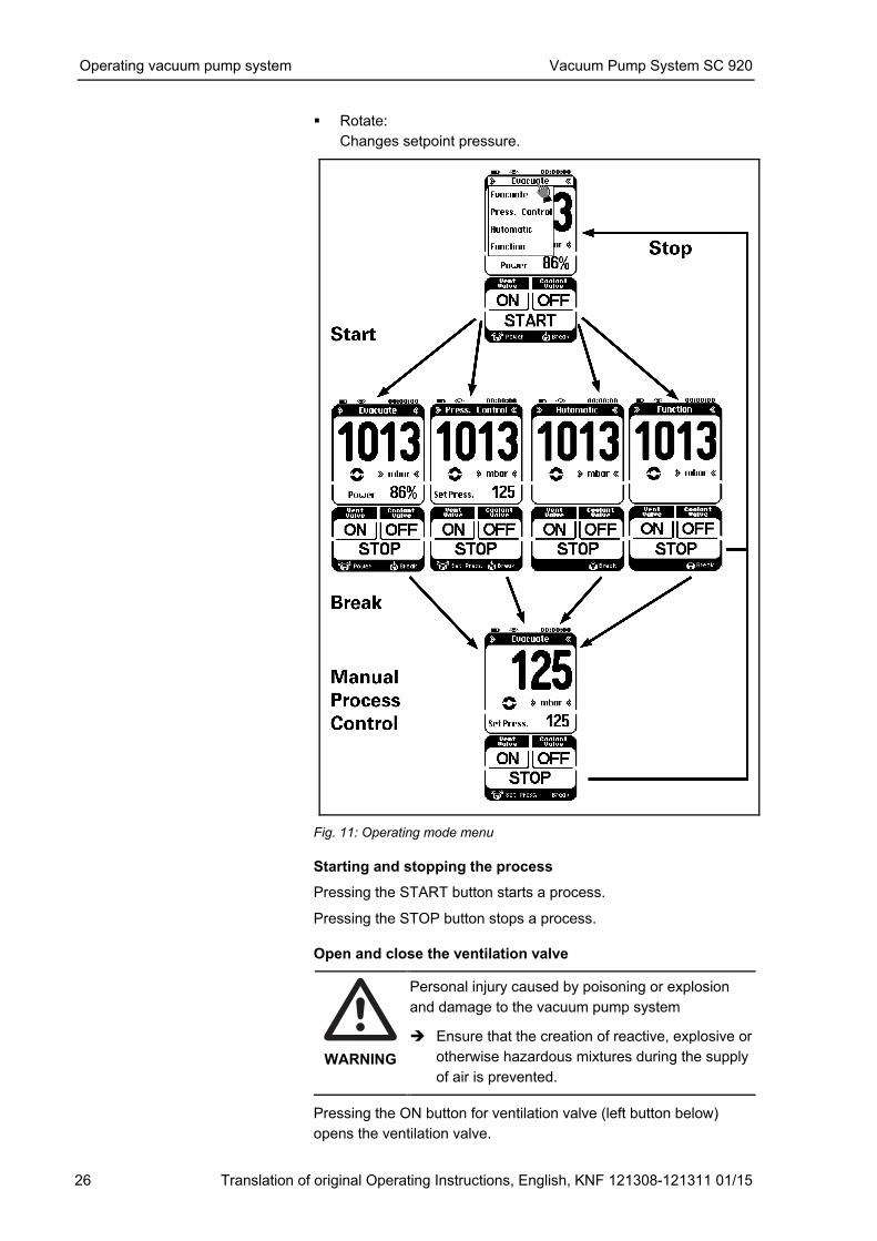
� Rotate:
Changes setpoint pressure.
Fig. 11: Operating mode menu
Starting and stopping the process
Pressing the START button starts a process.
Pressing the STOP button stops a process.
Open and close the ventilation valve
WARNING
Personal injury caused by poisoning or explosion
and damage to the vacuum pump system � Ensure that the creation of reactive, explosive or
otherwise hazardous mixtures during the supply
of air is prevented.
Pressing the ON button for ventilation valve (left button below)
opens the ventilation valve.
Vacuum Pump System SC 920 Operating vacuum pump system
Translation of original Operating Instructions, English, KNF 121308-121311 01/15 27
Pressing the OFF button for the ventilation valve closes the ventila-
tion valve.
Opening and closing coolant valve (accessory)
Pressing the ON button for coolant valve (right button below)
opens the coolant valve on the high-performance condenser.
Pressing the OFF button for the coolant valve closes the coolant
valve on the high-performance condenser.
Entering value in Evacuate operating mode
Use the rotating knob to set pump capacity.
Entering value in Pressure control operating mode
Use rotating knob to set desired pressure.
Entering value in Automatic operating mode
Not necessary to enter value.
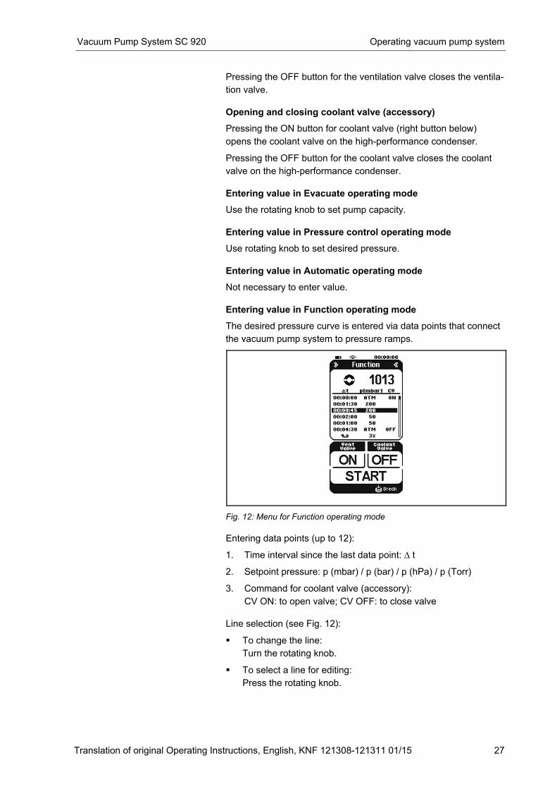
Entering value in Function operating mode
The desired pressure curve is entered via data points that connect
the vacuum pump system to pressure ramps.
Fig. 12: Menu for Function operating mode
Entering data points (up to 12):
1. Time interval since the last data point: ∆ t
2. Setpoint pressure: p (mbar) / p (bar) / p (hPa) / p (Torr)
3. Command for coolant valve (accessory):
CV ON: to open valve; CV OFF: to close valve
Line selection (see Fig. 12):
� To change the line:
Turn the rotating knob.
� To select a line for editing:
Press the rotating knob.
Operating vacuum pump system Vacuum Pump System SC 920
28 Translation of original Operating Instructions, English, KNF 121308-121311 01/15
To edit a selected line:
� To change columns:
(e.g. from ∆ t to p (mbar):
Press the rotating knob.
� To change an entry:
Turn the rotating knob.
After the last column (CV), the display automatically returns to
line selection and jumps to the next line.
If you are in input mode and have not entered any data within 3
seconds, the display automatically returns to line selection.
The function values of the data point table are stored in the
internal memory of the vacuum pump system when the
process starts, and are available again when there is a restart.
Changes to the function values (sampling point table) are
carried over directly from the PC software, which may be used
simultaneously.
Repeating/deleting sampling points:
The following symbols may be set in the column for the time
intervals under the value 00:00:00:
� = Repetition. The desired number of repetitions can now be specified in the field for the setpoint pressure.
� > = Deletion of the data point. In both cases, all subsequent sampling points are automatically
deleted.
Actuating the vacuum pump system (Paging)
When you press the circle symbol for the active process (Fig. 8/5,
page 24) in the hand terminal display, the LED next to the page
button (Fig. 14, page 30) on the vacuum pump system will blink.
The other way around, the hand terminal will answer with a signal
tone if you press the paging button of the vacuum pump system
(see chapter 8.2, page 30).
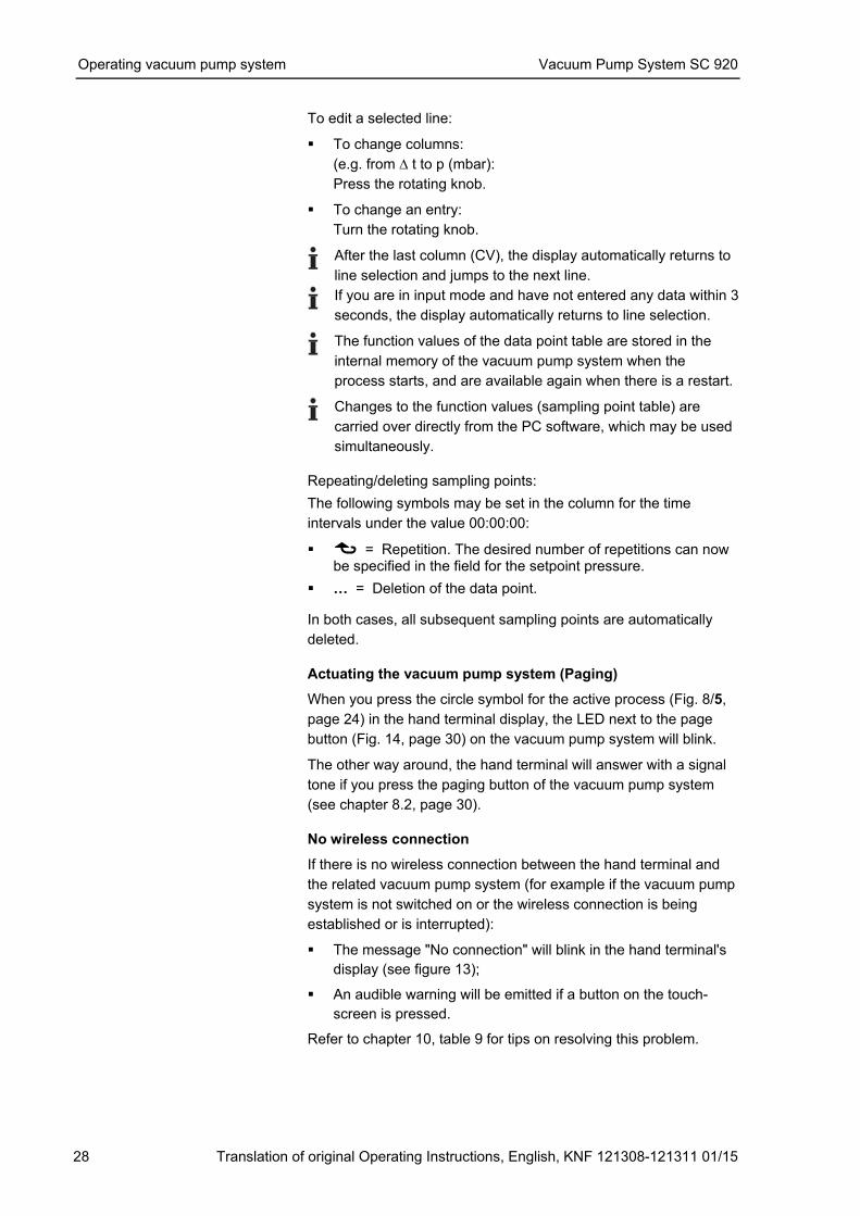
No wireless connection
If there is no wireless connection between the hand terminal and
the related vacuum pump system (for example if the vacuum pump
system is not switched on or the wireless connection is being
established or is interrupted):
� The message "No connection" will blink in the hand terminal's
display (see figure 13);
� An audible warning will be emitted if a button on the touch-
screen is pressed.
Refer to chapter 10, table 9 for tips on resolving this problem.
Vacuum Pump System SC 920 Operating vacuum pump system
Translation of original Operating Instructions, English, KNF 121308-121311 01/15 29
Fig. 13: Display „No connection“
8.1.3. Changing batteries on the hand terminal
1. Loosen the four screws on the underside of the hand terminal.
2. Remove the rear cover plate.
3. Replace the batteries.
Refer to chapter 4.2, page 9, for required battery specifica-
tions.
Never use new and used batteries together. Batteries must
always be replaced all at the same time.
4. Re-install cover plate.
5. Dispose of batteries according to regulations.
Operating vacuum pump system Vacuum Pump System SC 920
30 Translation of original Operating Instructions, English, KNF 121308-121311 01/15
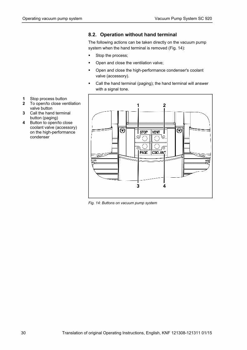
8.2. Operation without hand terminal
The following actions can be taken directly on the vacuum pump
system when the hand terminal is removed (Fig. 14):
� Stop the process;
� Open and close the ventilation valve;
� Open and close the high-performance condenser's coolant
valve (accessory).
� Call the hand terminal (paging); the hand terminal will answer
with a signal tone.
1 Stop process button 2 To open/to close ventilation
valve button 3 Call the hand terminal
button (paging) 4 Button to open/to close
coolant valve (accessory) on the high-performance condenser
Fig. 14: Buttons on vacuum pump system
Vacuum Pump System SC 920 Operating vacuum pump system
Translation of original Operating Instructions, English, KNF 121308-121311 01/15 31
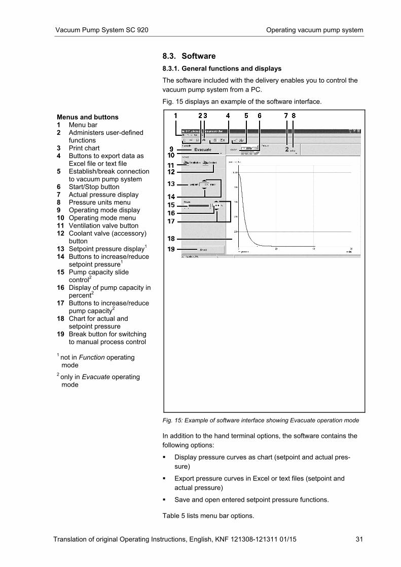
8.3. Software
8.3.1. General functions and displays
The software included with the delivery enables you to control the
vacuum pump system from a PC.
Fig. 15 displays an example of the software interface.
Menus and buttons 1 Menu bar 2 Administers user-defined
functions 3 Print chart 4 Buttons to export data as
Excel file or text file 5 Establish/break connection
to vacuum pump system 6 Start/Stop button 7 Actual pressure display 8 Pressure units menu 9 Operating mode display 10 Operating mode menu 11 Ventilation valve button 12 Coolant valve (accessory)
button 13 Setpoint pressure display
1
14 Buttons to increase/reduce setpoint pressure
1
15 Pump capacity slide control
2
16 Display of pump capacity in percent
2
17 Buttons to increase/reduce pump capacity
2
18 Chart for actual and setpoint pressure
19 Break button for switching to manual process control
1 not in Function operating mode
2 only in Evacuate operating mode
Fig. 15: Example of software interface showing Evacuate operation mode
In addition to the hand terminal options, the software contains the
following options:
� Display pressure curves as chart (setpoint and actual pres-
sure)
� Export pressure curves in Excel or text files (setpoint and
actual pressure)
� Save and open entered setpoint pressure functions.
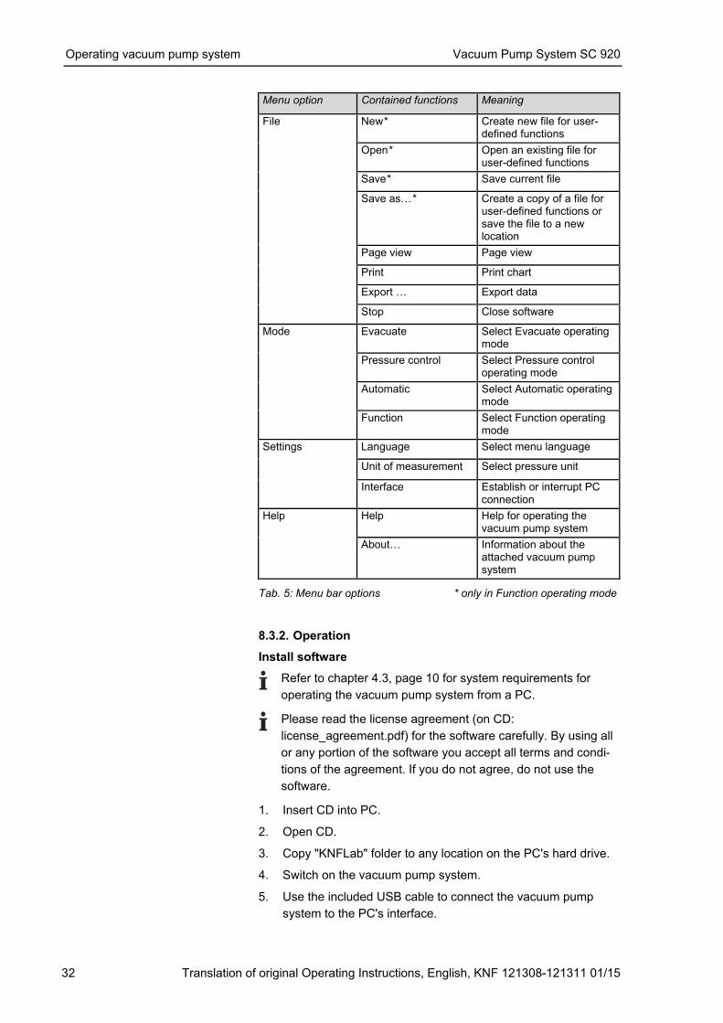
Table 5 lists menu bar options.
Operating vacuum pump system Vacuum Pump System SC 920
32 Translation of original Operating Instructions, English, KNF 121308-121311 01/15
Menu option Contained functions Meaning
File New* Create new file for user-defined functions
Open* Open an existing file for user-defined functions
Save* Save current file
Save asW* Create a copy of a file for user-defined functions or save the file to a new location
Page view Page view
Print Print chart
Export W Export data
Stop Close software
Mode Evacuate Select Evacuate operating mode
Pressure control Select Pressure control operating mode
Automatic Select Automatic operating mode
Function Select Function operating mode
Settings Language Select menu language
Unit of measurement Select pressure unit
Interface Establish or interrupt PC connection
Help Help Help for operating the vacuum pump system
AboutW Information about the attached vacuum pump system
Tab. 5: Menu bar options * only in Function operating mode
8.3.2. Operation
Install software
Refer to chapter 4.3, page 10 for system requirements for
operating the vacuum pump system from a PC.
Please read the license agreement (on CD:
license_agreement.pdf) for the software carefully. By using all
or any portion of the software you accept all terms and condi-
tions of the agreement. If you do not agree, do not use the
software. 1. Insert CD into PC.
2. Open CD.
3. Copy "KNFLab" folder to any location on the PC's hard drive.
4. Switch on the vacuum pump system.
5. Use the included USB cable to connect the vacuum pump
system to the PC's interface.
Vacuum Pump System SC 920 Operating vacuum pump system
Translation of original Operating Instructions, English, KNF 121308-121311 01/15 33
The USB port is located on the rear of the vacuum pump
system's base (see Fig. 3, page 11).
Windows will announce the presence of a new device and start
the installation wizard.
� Use the CD-ROM drive as the source for the driver.
The installation wizard will automatically install the driver.
6. Remove the CD from the PC and store it in a safe place.
7. Start the software by double-clicking on the file "KNFLab.exe";
this file is located on the hard drive in the new folder "KNFLab".
You may wish to place a shortcut to the file on your desktop.
Software functions are described under the Help menu entry.
Establishing and separating a connection from the PC to the vacuum pump system
The connection to the vacuum pump system is established and
separated by pressing the corresponding button (see figure 15/5,
page 31). If several vacuum pump systems are connected to the
PC, select the desired vacuum pump system from the list.
The connection to the vacuum pump system can also be estab-
lished through the toolbar "Settings � Interface � Connect". In the
dialog that appears you can directly select the communication
connection (if known) or click on the button "Test" to search with
the software. If several vacuum pump systems are connected,
select the desired vacuum pump system from the list.
Menu language
In the menu bar, choose between the following languages: English,
German, French, Italian, Spanish and Chinese.
Settings � Language
Pressure units
Process pressure can be displayed in mbar, bar, hPa, or Torr.
The pressure units can be changed as follows:
� through the menu bar:
Settings �Measurement units
� through the program:
Pressure units menu (Fig. 15/8, page 31)
Pressure units can be changed only when no process is active.
Operating modes
The operating mode can be changed in two different ways:
� Menu bar: Operating mode
� Diagram: Operating mode menu (Fig. 15/10, page 31)
Operating mode can be changed only when no process is
active.
Operating vacuum pump system Vacuum Pump System SC 920
34 Translation of original Operating Instructions, English, KNF 121308-121311 01/15
Starting and stopping the process
� Press START/STOP button (Fig. 15/6, page 31).
Open and close the ventilation valve
WARNING
Personal injury caused by poisoning or explosion
and damage to the vacuum pump system. � Make sure that no reactive or explosive mixtures
will be produced when ventilating the vacuum
pump system through the air inlet.
� Press Ventilation valve button (Fig. 15/11, page 31).
Open and close the coolant valve (accessory)
� Press Coolant valve button (Fig. 15/12, page 31).
Entering value in Evacuate operating mode
� Adjust pump capacity by moving slide control (Fig. 15/15, page
31), button (17) or display (16).
Entering value in Pressure control operating mode
� Set setpoint pressure with the Increase/decrease setpoint
pressure button (Fig. 15/14, page 31) or enter data into display
(13) via keybord.
Setpoint pressure can be changed only when no process is
active.
Entering value in Automatic operating mode
Not necessary to enter value.
Function operating mode
The desired pressure curve is entered via data points that connect
the vacuum pump system to pressure ramps.
The following entries must be made for each data point (up to 12):
� Time interval since the last data point
� Setpoint pressure
� Coolant valve (accessory):
− No action
− Open (W)
− Close (W).
The values can be entered either through the table or through the
chart (Fig. 16, page 35).
Entry through the diagram:
� Insert data point:
Right-click on the function curve and select the desired action
from the menu that appears.
� Shifting data point:
Left-click on the data point and move it as desired.
Vacuum Pump System SC 920 Operating vacuum pump system
Translation of original Operating Instructions, English, KNF 121308-121311 01/15 35
� Delete data point / specify action for coolant valve (accessory):
Right-click on the point and select the desired action from the
menu that appears.
The action of the coolant valve is set by double-clicking in the
corresponding field of the “Cooling” column. A menu opens con-
taining the selectable actions ON (open valve) and OFF (close
valve).
Repetitions of the function are set in the first empty line below the
sampling points entered. Double-clicking in the field in the “Cool-
ing” column opens a menu containing the REPEAT option. If this is
activated, the desired number of repetitions can then be entered in
the field of the “p [...]” column.
In order to delete a data point, remove the corresponding entry in
the dt column. The subsequent sampling points are automatically
moved up in the column.
Start the user-defined function by clicking on the START button.
The process will stop automatically after reaching the end of the
setpoint pressure curve.
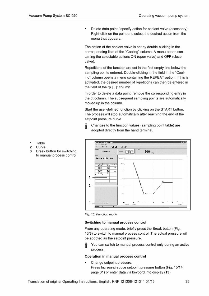
Changes to the function values (sampling point table) are
adopted directly from the hand terminal.
1 Table 2 Curve 3 Break button for switching
to manual process control
Fig. 16: Function mode
Switching to manual process control
From any operating mode, briefly press the Break button (Fig.
16/3) to switch to manual process control. The actual pressure will
be adopted as the setpoint pressure.
You can switch to manual process control only during an active
process. Operation in manual process control
� Change setpoint pressure:
Press Increase/reduce setpoint pressure button (Fig. 15/14,
page 31) or enter data via keybord into display (13).
Operating vacuum pump system Vacuum Pump System SC 920
36 Translation of original Operating Instructions, English, KNF 121308-121311 01/15
� Evacuation:
Press the break button (Fig. 15/19, page 31). When the button
is released, the actual pressure will in turn be adopted as the
setpoint pressure for the pressure regulation.
� Changing to an operating mode:
1. Press STOP button.
2. Select operating mode through the menu bar or chart (Operat-
ing mode menu (Fig. 15/10, page 31)).
You can switch to an operating mode only when no process is
active.
Vacuum Pump System SC 920 Servicing
Translation of original Operating Instructions, English, KNF 121308-121311 01/15 37
9. Servicing
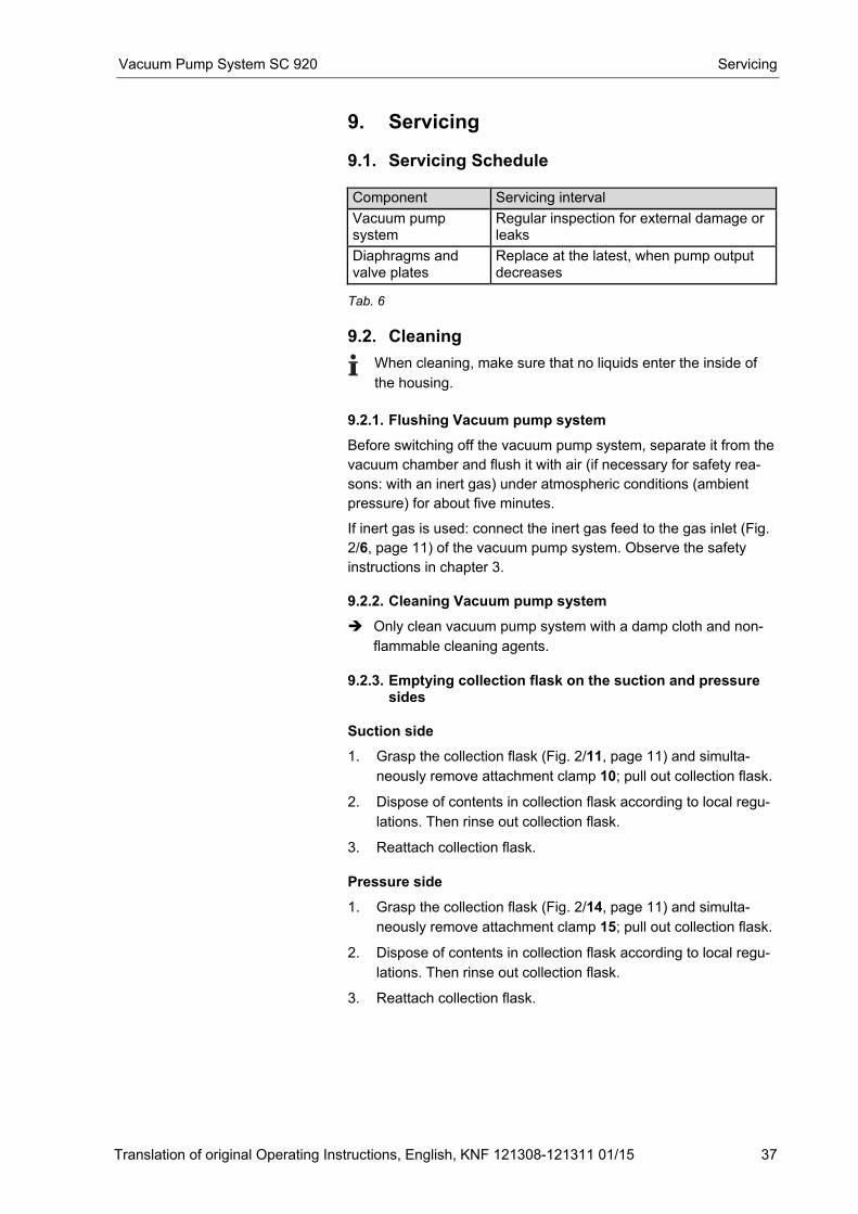
9.1. Servicing Schedule Component Servicing interval
Vacuum pump system
Regular inspection for external damage or leaks
Diaphragms and valve plates
Replace at the latest, when pump output decreases
Tab. 6
9.2. Cleaning
When cleaning, make sure that no liquids enter the inside of
the housing.
9.2.1. Flushing Vacuum pump system
Before switching off the vacuum pump system, separate it from the
vacuum chamber and flush it with air (if necessary for safety rea-
sons: with an inert gas) under atmospheric conditions (ambient
pressure) for about five minutes.
If inert gas is used: connect the inert gas feed to the gas inlet (Fig.
2/6, page 11) of the vacuum pump system. Observe the safety
instructions in chapter 3.
9.2.2. Cleaning Vacuum pump system
� Only clean vacuum pump system with a damp cloth and non-
flammable cleaning agents.
9.2.3. Emptying collection flask on the suction and pressure
sides
Suction side
1. Grasp the collection flask (Fig. 2/11, page 11) and simulta-
neously remove attachment clamp 10; pull out collection flask.
2. Dispose of contents in collection flask according to local regu-
lations. Then rinse out collection flask.
3. Reattach collection flask.
Pressure side
1. Grasp the collection flask (Fig. 2/14, page 11) and simulta-
neously remove attachment clamp 15; pull out collection flask.
2. Dispose of contents in collection flask according to local regu-
lations. Then rinse out collection flask.
3. Reattach collection flask.
Servicing Vacuum Pump System SC 920
38 Translation of original Operating Instructions, English, KNF 121308-121311 01/15
9.3. Changing Diaphragms and Valve Plates
� Vacuum pump system is switched off and mains plug is
removed from the socket
� Vacuum pump system is clean and free of hazardous materials
Qty Material
1 Phillips-head screwdriver No. 2
1 4-mm hexagon screwdriver
1 Service Set (see chapter 11, page 48)
1 Felt-tip pen
1 Stabilization diaphragm (if required) Tab. 7
� Always replace diaphragms and valve plates together to
maintain the pump performance.
WARNING
Health hazard due to dangerous substances
in the vacuum pump system and pump!
Depending on the substance transferred, caustic
burns or poisoning are possible.
� Wear protective clothing if necessary, e.g.
protective gloves.
� Flush vacuum pump system before replacing the
diaphragms and valve plates (see chapter 9.2.1,
page 37).
Remove pump head
1. Remove tubing from the inlet and outlet connectors of the
pump.
2. Undo the two screws (1) and nine screws (2) of the head cover
(3).
3. Undo two screws (6) each, and remove both covers (5) at head
cover (4).
4. Lift the head cover (3) off the pump housing (19).
5. Lift off head plate (9) with intermediate plates (11), (14) and
(15).
Conditions
Tools and material
Information on procedure
Vacuum Pump System SC 920 Servicing
Translation of original Operating Instructions, English, KNF 121308-121311 01/15 39
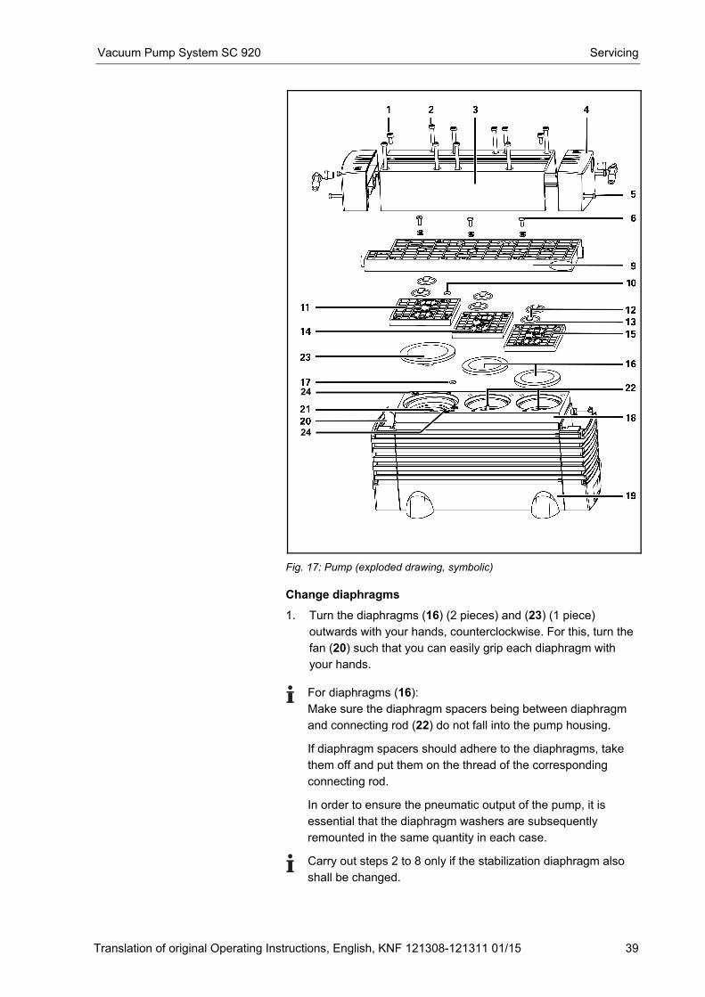
Fig. 17: Pump (exploded drawing, symbolic)
Change diaphragms
1. Turn the diaphragms (16) (2 pieces) and (23) (1 piece)
outwards with your hands, counterclockwise. For this, turn the
fan (20) such that you can easily grip each diaphragm with
your hands.
For diaphragms (16):
Make sure the diaphragm spacers being between diaphragm
and connecting rod (22) do not fall into the pump housing. If diaphragm spacers should adhere to the diaphragms, take
them off and put them on the thread of the corresponding
connecting rod. In order to ensure the pneumatic output of the pump, it is
essential that the diaphragm washers are subsequently
remounted in the same quantity in each case.
Carry out steps 2 to 8 only if the stabilization diaphragm also
shall be changed.
24
24
Servicing Vacuum Pump System SC 920
40 Translation of original Operating Instructions, English, KNF 121308-121311 01/15
2. Loosen the two screws (24) and remove the adapter (18) from
the pump housing (19).
The stabilization diaphragm (21) is now visible.
3. Remove the existing diaphragm spacers from the stabilization
diaphragm (21).
It is important to later re-install the same quantity of diaphragm
spacers in order to ensure the pump's pneumatic performance. 4. Use the assembly key to loosen the stabilization diaphragm
(21) and then manually screw it out (in the counterclockwise
direction).
5. Screw in the new stabilization diaphragm (21) and tighten it
hand-tight with the assembly key.
6. Put spacer(s) onto the thread of the new stabilization
diaphragm (21) (same number).
7. Place the adapter (18) onto the pump housing (19).
The adapter must be aligned flush with the pump housing (19).
This is important for later installation of the diaphragm (23). 8. Tighten the two screws (24) to hand-tightness.
Begin with the outermost screw and make sure that the
adapter (18) does not move while you are tightening the
screws. 9. Screw the new diaphragm (23) into the thread of the
stabilization diaphragm (21) and tighten it by hand.
To ensure proper pump performance, it is important to
maintain a uniform distance everywhere between the outer
edge of the diaphragm (23) and the adapter (18). If the
distance is not uniform, you must re-loosen the screws (24)
and re-align the adapter so the distance is the same
everywhere. 10. Screw the new diaphragms (16) onto the connecting rods (22)
and tighten it by hand.
Before you finally tighten the diaphragm, you are
recommended to move the diaphragm to the upper dead
center by rotating the fan (20).
11. Exchange the O-ring (17) for a new one in adapter (18).
12. Put head plate (9) with intermediate plates (11), (14) and (15)
on adapter (18).
Change valve plates
1. Mark the position of head plate (9) and intermediate plate (11)
relative to each other by a drawing line with a felt-tip pen. This
helps avoid incorrect assembly later.
2. Mark the position of head plate (9) and intermediate plate (14)
relative to each other by two drawing lines with a felt-tip pen.
Vacuum Pump System SC 920 Servicing
Translation of original Operating Instructions, English, KNF 121308-121311 01/15 41
3. Mark the position of head plate (9) and intermediate plate (15)
relative to each other by three drawing lines with a felt-tip pen.
4. Undo the three screws (6) in head plate (9) and remove head
plate from intermediate plates (11), (14) and (15).
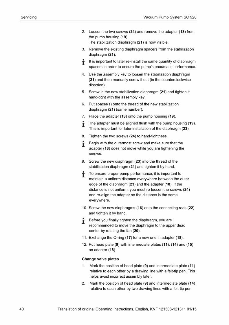
5. Remove valve plates (12) and O-rings (13) from intermediate
plates (11), (14) and (15).
Instead of lying on intermediate plate, O-rings could stick to
head plate (9).
6. Remove O-ring (10) from intermediate plate (11) and
exchange it for a new one.
7. Lay the new valve plates (12) and the new O-rings (13) on the
intermediate plates (11), (14) and (15).
Upper and lower sides of the valve plates are identical. For
correct position see fig. 18.
8. Dispose of the old diaphragms and valve plates/sealings
properly.
Mount pump head
1. Place head plate (9) on intermediate plates (11), (14) and (15)
in the position indicated by the drawing lines.
� At the front edge the three intermediate plates must lie in a line
on which head plate is placed flushly.
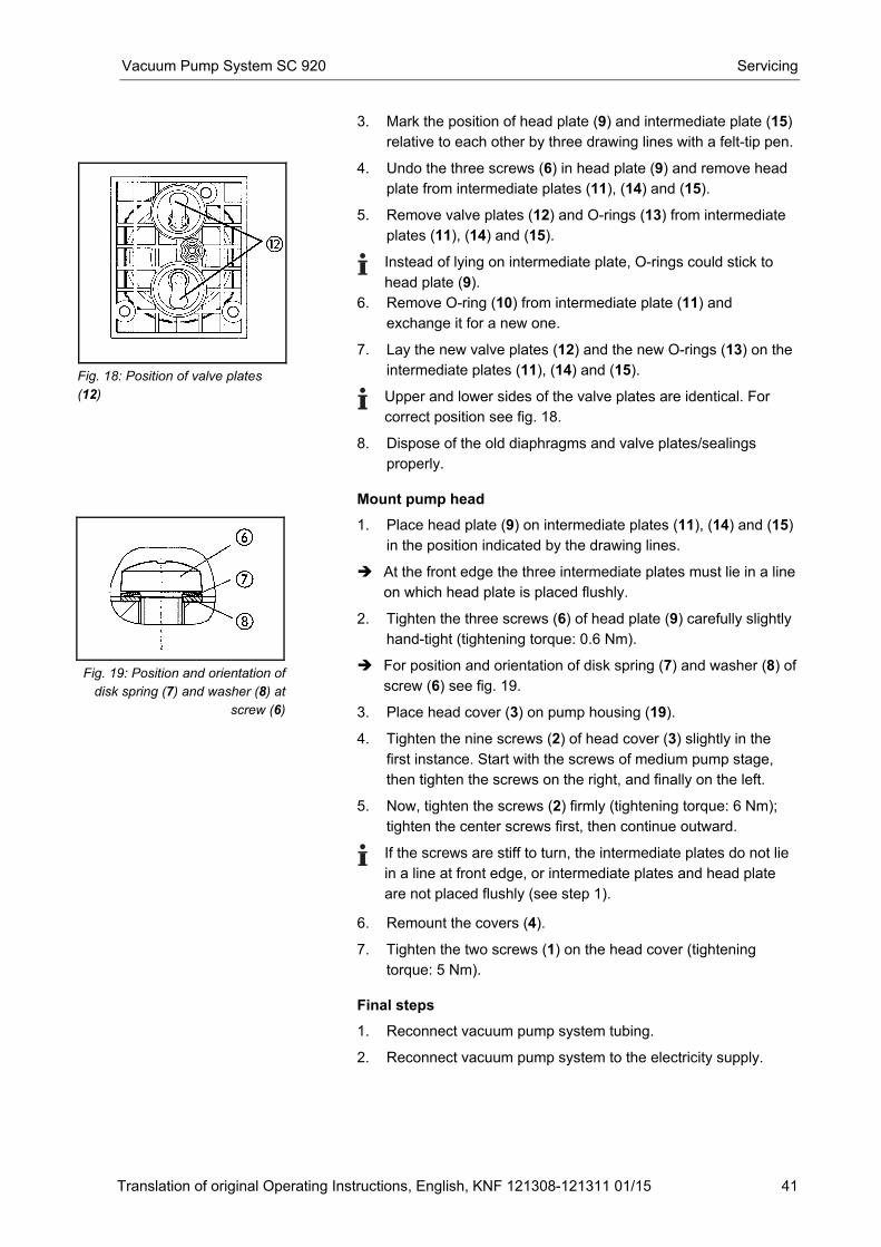
2. Tighten the three screws (6) of head plate (9) carefully slightly
hand-tight (tightening torque: 0.6 Nm).
� For position and orientation of disk spring (7) and washer (8) of
screw (6) see fig. 19.
3. Place head cover (3) on pump housing (19).
4. Tighten the nine screws (2) of head cover (3) slightly in the
first instance. Start with the screws of medium pump stage,
then tighten the screws on the right, and finally on the left.
5. Now, tighten the screws (2) firmly (tightening torque: 6 Nm);
tighten the center screws first, then continue outward.
If the screws are stiff to turn, the intermediate plates do not lie
in a line at front edge, or intermediate plates and head plate
are not placed flushly (see step 1). 6. Remount the covers (4).
7. Tighten the two screws (1) on the head cover (tightening
torque: 5 Nm).
Final steps
1. Reconnect vacuum pump system tubing.
2. Reconnect vacuum pump system to the electricity supply.
Fig. 18: Position of valve plates
(12)
Fig. 19: Position and orientation of
disk spring (7) and washer (8) at
screw (6)
Servicing Vacuum Pump System SC 920
42 Translation of original Operating Instructions, English, KNF 121308-121311 01/15
9.4. Replace overpressure valve on high performance condenser
� Vacuum pump system is switched off and mains plug is
removed from the socket
� Vacuum pump system is clean and free of hazardous materials
WARNING
Health hazard due to dangerous substances
in the vacuum pump system and pump!
Depending on the substance transferred, caustic
burns or poisoning are possible.
� Wear protective clothing if necessary, e.g.
protective gloves.
� Flush vacuum pump system before replacing
overpressure valve (see chapter 9.2.1, page 37).
1. Unscrew and remove hose nozzle which connects the high
performance condenser with the pressure side of the pump
from high performance condenser.
2. Detach the old overpressure valve from screw socket of high
performance condenser.
3. Slide on the new overpressure valve. Be aware that the
overpressure port is completely covered.
4. Reconnect high performance condenser with pump.
Conditions
Information on procedure
Vacuum Pump System SC 920 Troubleshooting
Translation of original Operating Instructions, English, KNF 121308-121311 01/15 43
10. Troubleshooting
DANGER
Extreme danger from electrical shock!
� Disconnect the pump power supply before working
on the pump.
� Make sure the pump is de-energized and secure.
� Vacuum pump system as a whole: see table 8.
� Hand terminal: see table 9.
� Software operation: see table 10.
Vacuum pump system as a whole
Problem Cause Solution
Vacuum pump system is switched on, but the mains switch does not light up.
Mains cable not plugged in. � Plug the mains cable for the vacuum pump system into a properly grounded power socket.
No current in electricity network.
� Check the electricity supply.
Vacuum pump system fuses blown.
1. Find and eliminate the cause of the overload.
2. Replace the mains fuse(s) of the vacuum pump system:
� Push the locking clip on the fuse drawer down (Fig. 3/4, p. 11) and pull the drawer out.
� Replace the defective fuse(s) (for fuse specifications see chapter 4.1, page 8; for fuse order numbers see chapter 11, p. 48).
� Push the fuse drawer back in until it clicks into position.
Required vacuum not generated even though pump is running.
Leaks in vacuum chamber. 1. Run a test by closing the gas inlet (Fig. 2/6,p. 11). If the pump reaches the required vacuum, this confirms the presence of leaks in the vacuum chamber.
2. Eliminate leaks in the vacuum chamber.
O-ring is not sitting correctly in the slot on the suction side of the collection flask.
� Adjust O-ring.
� Replace if defective (for order number for O-ring, see chapter 11, p. 48).
Leaks in hose connection. � Check hoses are sitting correctly on hose nipples.
� Replace any leaky hoses.
� Replace any damaged hose nipples.
� For ordering numbers see chapter 11, page 48.
Hexagonal gland (Fig. 2/6, p. 11) loose.
� Carefully tighten hexagonal gland with wrench.
Troubleshooting Vacuum Pump System SC 920
44 Translation of original Operating Instructions, English, KNF 121308-121311 01/15
Vacuum pump system as a whole
Problem Cause Solution
Leaks in venting valve. � Temporarily close the ventilation connection (Fig. 2/5, p. 11). If this stops the leak, leaks are present in the venting valve. In this case:
� Flush the venting valve:
1. Close the gas inlet (Fig. 2/6).
2. If necessary for safety reasons: Connect inert gas to ventilation connection. Observe the safety instructions in chapter 3.
3. Run the vacuum pump system at 100% pump capacity in evacuation mode.
4. Re-open the gas inlet.
� If problem persists, contact KNF Service.
Condensation in pump head.
� Dry system with fresh air or, if necessary for safety reasons, with an inert gas:
1. Using inert gas: Connect inert gas source with gas inlet (Fig. 2/6, p. 11) and start system up in evacuation mode (100% capacity). Observe the safety instructions in chapter 3.
2. Using air: Open gas line (Fig. 2/6, p. 11) to the surrounding environment and start system up in evacuation mode (100% capacity).
3. Close the gas inlet after 30 seconds, and leave the vacuum pump system running for 30 seconds under vacuum.
4. Repeat this process 3–5 times.
� If this problem occurs frequently, place the vacuum pump system at a higher level than the vacuum chamber.
Gas outlet blocked on high-performance condenser.
Risk of bursting of high-performance condenser!
� Eliminate blocking of gas outlet.
Worn diaphragms or valve plates.
� Replace diaphragms and valve plates (chapter 9.3).
Replaced diaphragms and valve plates.
� Check that the correct diaphragm spacers are placed under the diaphragms.
� If necessary, carefully tighten the pump head fixing screws (Fig. 17/2, p. 39) in diagonally opposite sequence.
Pump not activated on process start-up, in spite of pressure decrease command.
Hand terminal or software not connected to vacuum pump system.
� Make connection.
Vacuum Pump System SC 920 Troubleshooting
Translation of original Operating Instructions, English, KNF 121308-121311 01/15 45
Vacuum pump system as a whole
Problem Cause Solution
Overcurrent protection of vacuum pump system has been activated.
� Reset by switching the vacuum pump system off and back on.
� Check that there is no object blocking the pump fan (Fig. 17/20, p. 39) and make sure that adequate supply and removal of cool air is provided.
� Find and eliminate any other cause of pump overload.
Noisy pump. Leaking hose connection. � Check that hoses are sitting correctly on hose nipples.
� Replace any leaking hoses.
� Replace any damaged hose nipples.
Leaks at hose nipple on high-performance condenser.
� Tighten hose nipple at gas outlet (Fig. 2/16, p. 11).
Leaks in overpressure valve on high-performance condenser.
� Check overpressure valve is sitting correctly; replace if necessary. For ordering number see chapter 11, page 48.
Tab. 8
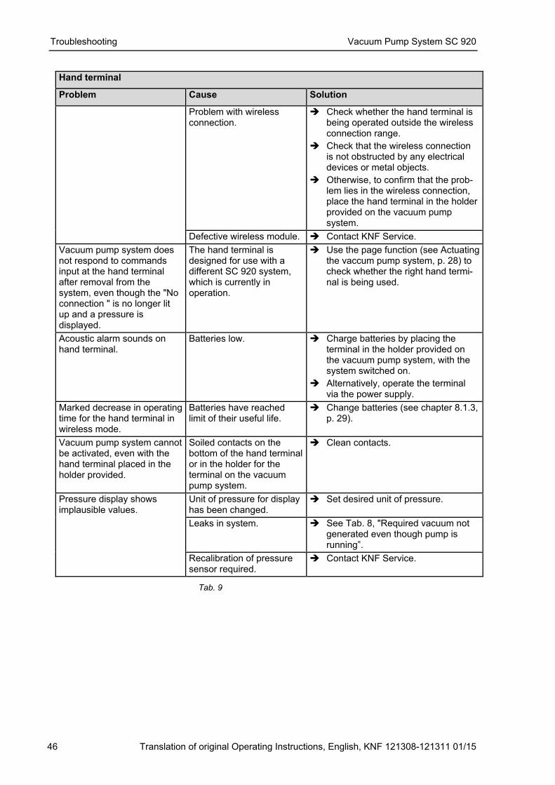
Hand terminal
Problem Cause Solution
Hand terminal cannot be removed from vacuum pump system.
Transport fastener has not been removed.
� Remove transport fastener (see chapter 6, p. 17).
Hand terminal display fails to light up.
Hand terminal not switched on.
� Switch hand terminal on.
Batteries of hand terminal have run down.
� Charge batteries by placing the terminal in the holder provided on the vacuum pump system, with the system switched on.
� Alternatively, operate the terminal via the power supply.
The hand terminal display keeps showing "No connec-tion"; if a button of the touch-screen is actuated a signal tone sounds.
Vacuum pump system is switched off.
� Switch the vacuum pump system on at the mains switch. The mains switch should light up.
The hand terminal is designed for use with a different SC 920 vacuum pump system.
� Use the page function (see Actuating the vaccum pump system, p. 28) to check whether the right hand termi-nal is being used.
Troubleshooting Vacuum Pump System SC 920
46 Translation of original Operating Instructions, English, KNF 121308-121311 01/15
Hand terminal
Problem Cause Solution
Problem with wireless connection.
� Check whether the hand terminal is being operated outside the wireless connection range.
� Check that the wireless connection is not obstructed by any electrical devices or metal objects.
� Otherwise, to confirm that the prob-lem lies in the wireless connection, place the hand terminal in the holder provided on the vacuum pump system.
Defective wireless module. � Contact KNF Service.
Vacuum pump system does not respond to commands input at the hand terminal after removal from the system, even though the "No connection " is no longer lit up and a pressure is displayed.
The hand terminal is designed for use with a different SC 920 system, which is currently in operation.
� Use the page function (see Actuating the vaccum pump system, p. 28) to check whether the right hand termi-nal is being used.
Acoustic alarm sounds on hand terminal.
Batteries low. � Charge batteries by placing the terminal in the holder provided on the vacuum pump system, with the system switched on.
� Alternatively, operate the terminal via the power supply.
Marked decrease in operating time for the hand terminal in wireless mode.
Batteries have reached limit of their useful life.
� Change batteries (see chapter 8.1.3, p. 29).
Vacuum pump system cannot be activated, even with the hand terminal placed in the holder provided.
Soiled contacts on the bottom of the hand terminal or in the holder for the terminal on the vacuum pump system.
� Clean contacts.
Pressure display shows implausible values.
Unit of pressure for display has been changed.
� Set desired unit of pressure.
Leaks in system. � See Tab. 8, "Required vacuum not generated even though pump is running”.
Recalibration of pressure sensor required.
� Contact KNF Service.
Tab. 9
Vacuum Pump System SC 920 Troubleshooting
Translation of original Operating Instructions, English, KNF 121308-121311 01/15 47
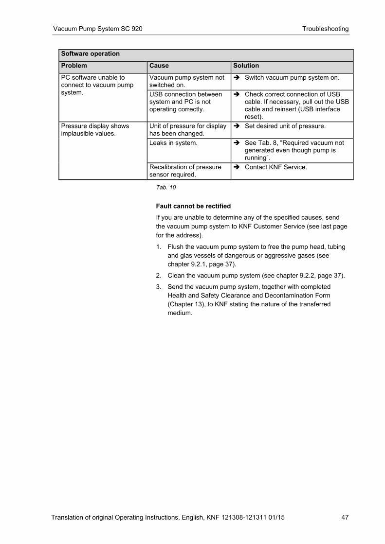
Software operation
Problem Cause Solution
PC software unable to connect to vacuum pump system.
Vacuum pump system not switched on.
� Switch vacuum pump system on.
USB connection between system and PC is not operating correctly.
� Check correct connection of USB cable. If necessary, pull out the USB cable and reinsert (USB interface reset).
Pressure display shows implausible values.
Unit of pressure for display has been changed.
� Set desired unit of pressure.
Leaks in system. � See Tab. 8, "Required vacuum not generated even though pump is running”.
Recalibration of pressure sensor required.
� Contact KNF Service.
Tab. 10
Fault cannot be rectified
If you are unable to determine any of the specified causes, send
the vacuum pump system to KNF Customer Service (see last page
for the address).
1. Flush the vacuum pump system to free the pump head, tubing
and glas vessels of dangerous or aggressive gases (see
chapter 9.2.1, page 37).
2. Clean the vacuum pump system (see chapter 9.2.2, page 37).
3. Send the vacuum pump system, together with completed
Health and Safety Clearance and Decontamination Form
(Chapter 13), to KNF stating the nature of the transferred
medium.
Ordering Information Vacuum Pump System SC 920
48 Translation of original Operating Instructions, English, KNF 121308-121311 01/15
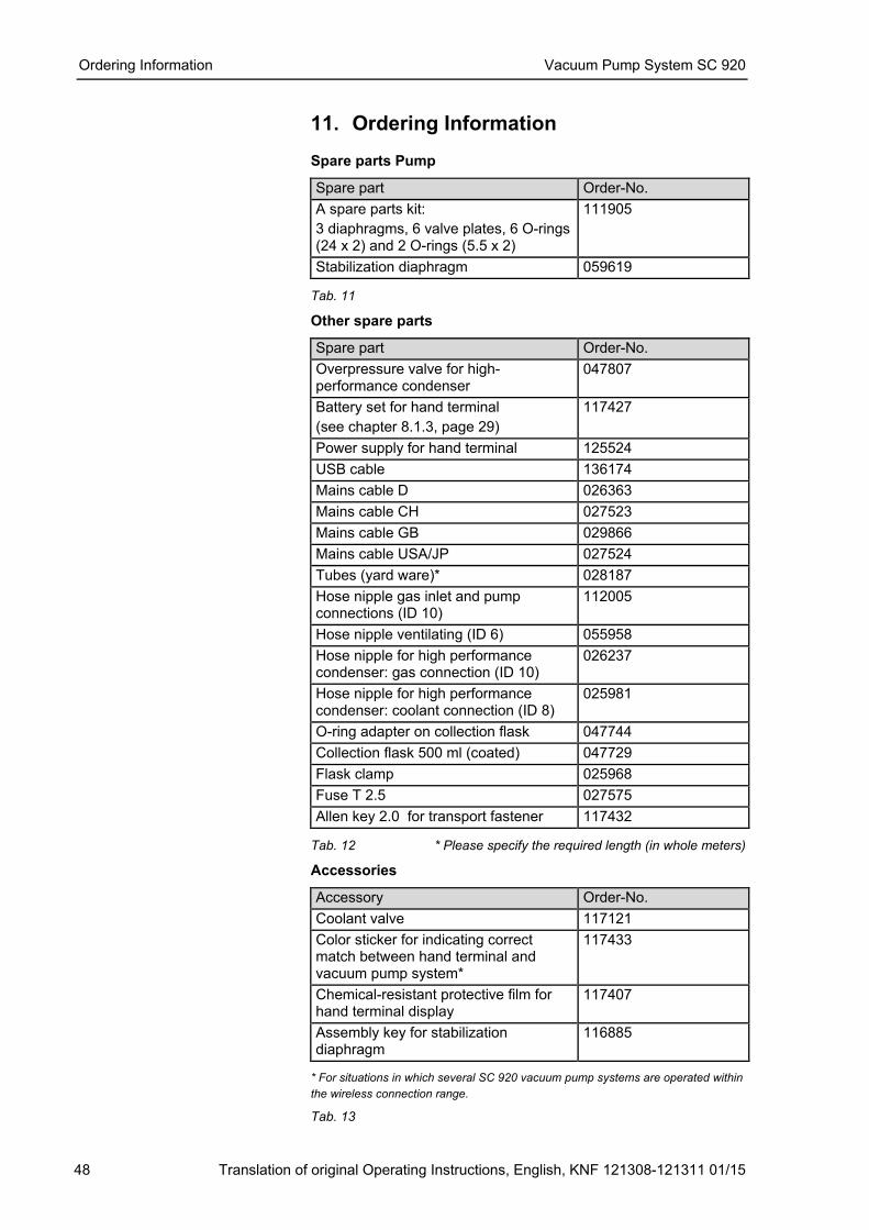
11. Ordering Information Spare parts Pump
Spare part Order-No.
A spare parts kit:
3 diaphragms, 6 valve plates, 6 O-rings (24 x 2) and 2 O-rings (5.5 x 2)
111905
Stabilization diaphragm 059619 Tab. 11
Other spare parts
Spare part Order-No.
Overpressure valve for high-performance condenser
047807
Battery set for hand terminal
(see chapter 8.1.3, page 29)
117427
Power supply for hand terminal 125524
USB cable 136174
Mains cable D 026363
Mains cable CH 027523
Mains cable GB 029866
Mains cable USA/JP 027524
Tubes (yard ware)* 028187
Hose nipple gas inlet and pump connections (ID 10)
112005
Hose nipple ventilating (ID 6) 055958
Hose nipple for high performance condenser: gas connection (ID 10)
026237
Hose nipple for high performance condenser: coolant connection (ID 8)
025981
O-ring adapter on collection flask 047744
Collection flask 500 ml (coated) 047729
Flask clamp 025968
Fuse T 2.5 027575
Allen key 2.0 for transport fastener 117432 Tab. 12 * Please specify the required length (in whole meters)
Accessories
Accessory Order-No.
Coolant valve 117121
Color sticker for indicating correct match between hand terminal and vacuum pump system*
117433
Chemical-resistant protective film for hand terminal display
117407
Assembly key for stabilization diaphragm
116885
* For situations in which several SC 920 vacuum pump systems are operated within
the wireless connection range.
Tab. 13
Vacuum Pump System SC 920 Returns
Translation of original Operating Instructions, English, KNF 121308-121311 01/15 49
12. Returns
Pumps and systems used in laboratories and process-based
industries are exposed to a wide variety of conditions. This means
that the components contacting pumped media could become
contaminated by toxic, radioactive, or otherwise hazardous
substances.
For this reason, customers who send any pumps or systems back
to KNF must submit a Health and safety clearance and
decontamination form in order to avoid a hazardous situation for
KNF employees. This Health and safety clearance and
decontamination form provides the following information, among
other things:
� physiological safety
� whether medium-contacting parts have been cleaned
� whether the equipment has been decontaminated
� media that have been pumped or used
and must declare physiological safety. To ensure worker safety,
work may not be started on pumps or systems without a signed
Health and safety clearance and decontamination form.
For optimal processing of a return, a copy of this declaration
should be sent in advance via e-mail, regular mail, or fax to KNF
Customer Service (refer to final page for address). In order to avoid
endangering employees who open the shipment's packaging,
despite any residual hazards, the original version of the Health and
safety clearance and decontamination form must accompany the
delivery receipt on the outside of the packing.
The template for the Health and safety clearance and
decontamination form is included with these Operating Instructions
and may also be downloaded from the KNF website.
The customer must specify the device type(s) and serial number(s)
in the Health and safety clearance and decontamination form in
order to provide for the unambiguous assignment of the
Declaration to the device that is sent to KNF.
In addition to the customer's declaration of physiological safety,
information about operating conditions and the customer's
application are also of importance to ensure that the return
shipment is handled appropriately. Therefore, the Health and
safety clearance and decontamination form requests this
information as well.
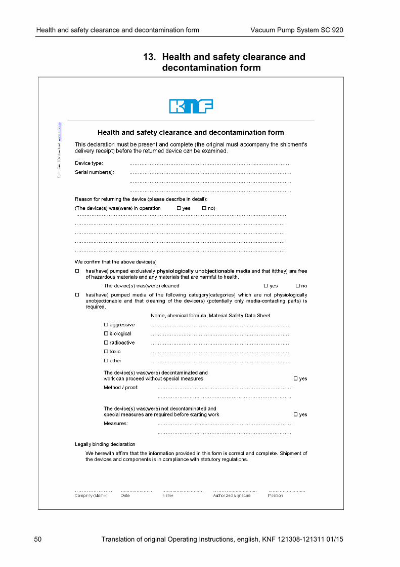
Health and safety clearance and decontamination form Vacuum Pump System SC 920
50 Translation of original Operating Instructions, english, KNF 121308-121311 01/15
13. Health and safety clearance and decontamination form
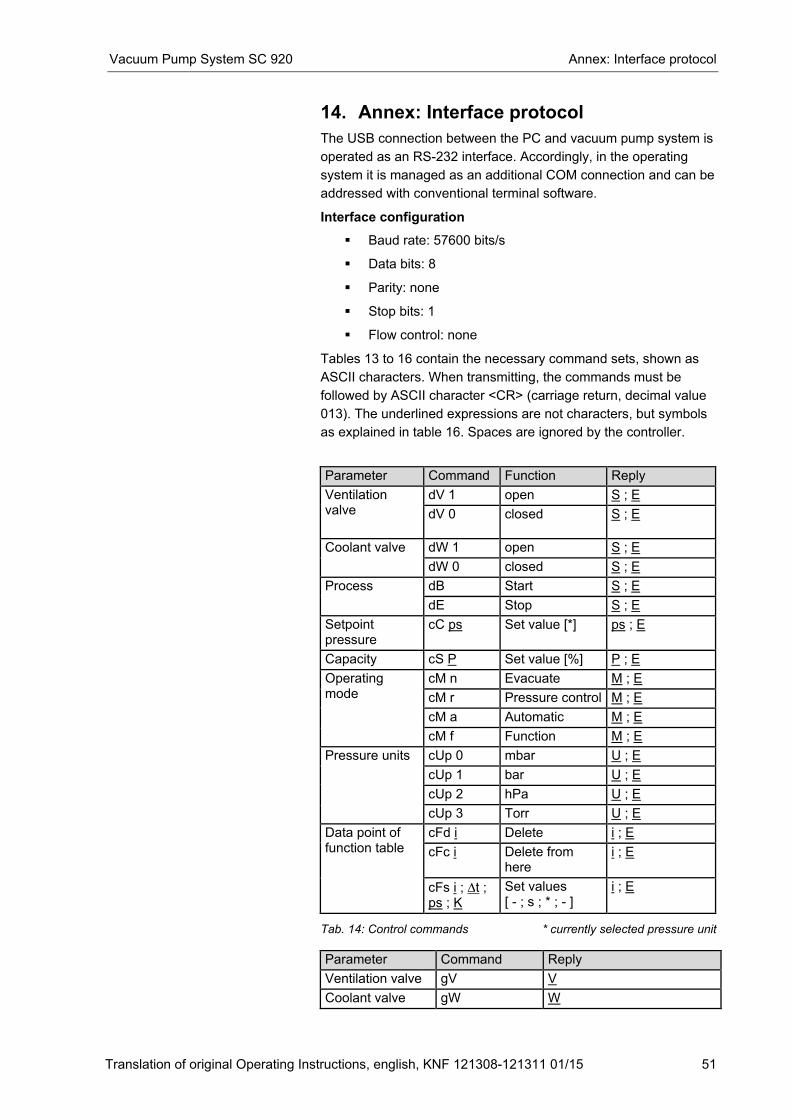
Vacuum Pump System SC 920 Annex: Interface protocol
Translation of original Operating Instructions, english, KNF 121308-121311 01/15 51
14. Annex: Interface protocol
The USB connection between the PC and vacuum pump system is
operated as an RS-232 interface. Accordingly, in the operating
system it is managed as an additional COM connection and can be
addressed with conventional terminal software.
Interface configuration
� Baud rate: 57600 bits/s
� Data bits: 8
� Parity: none
� Stop bits: 1
� Flow control: none
Tables 13 to 16 contain the necessary command sets, shown as
ASCII characters. When transmitting, the commands must be
followed by ASCII character <CR> (carriage return, decimal value
013). The underlined expressions are not characters, but symbols
as explained in table 16. Spaces are ignored by the controller.
Parameter Command Function Reply
Ventilation valve
dV 1 open S ; E
dV 0 closed S ; E
Coolant valve
dW 1 open S ; E
dW 0 closed S ; E
Process
dB Start S ; E
dE Stop S ; E
Setpoint pressure
cC ps Set value [*] ps ; E
Capacity cS P Set value [%] P ; E
Operating mode
cM n Evacuate M ; E
cM r Pressure control M ; E
cM a Automatic M ; E
cM f Function M ; E
Pressure units
cUp 0 mbar U ; E
cUp 1 bar U ; E
cUp 2 hPa U ; E
cUp 3 Torr U ; E
Data point of function table
cFd i Delete i ; E
cFc i Delete from here
i ; E
cFs i ; ∆t ; ps ; K
Set values [ - ; s ; * ; - ]
i ; E
Tab. 14: Control commands * currently selected pressure unit
Parameter Command Reply
Ventilation valve gV V
Coolant valve gW W
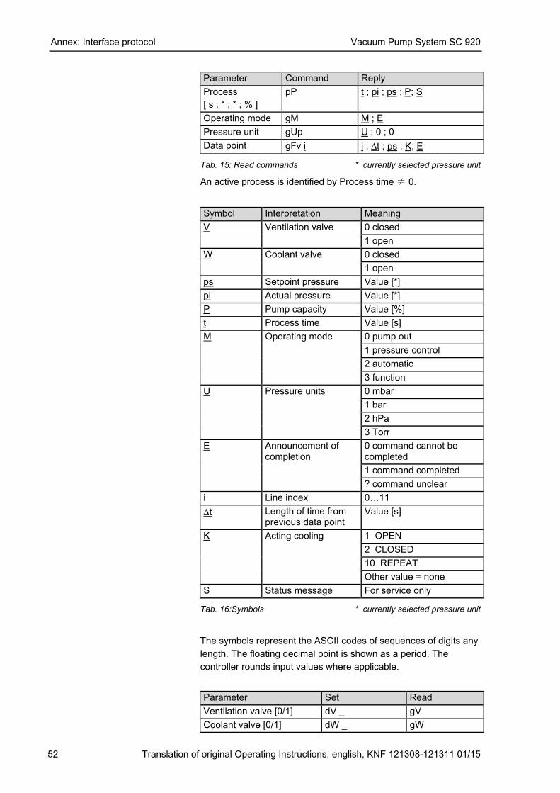
Annex: Interface protocol Vacuum Pump System SC 920
52 Translation of original Operating Instructions, english, KNF 121308-121311 01/15
Parameter Command Reply
Process
[ s ; * ; * ; % ]
pP t ; pi ; ps ; P; S
Operating mode gM M ; E
Pressure unit gUp U ; 0 ; 0
Data point gFv i i ; ∆t ; ps ; K; E Tab. 15: Read commands * currently selected pressure unit
An active process is identified by Process time ≠ 0.
Symbol Interpretation Meaning
V Ventilation valve 0 closed
1 open
W Coolant valve 0 closed
1 open
ps Setpoint pressure Value [*]
pi Actual pressure Value [*]
P Pump capacity Value [%]
t Process time Value [s]
M Operating mode
0 pump out
1 pressure control
2 automatic
3 function
U Pressure units
0 mbar
1 bar
2 hPa
3 Torr
E Announcement of completion
0 command cannot be completed
1 command completed
? command unclear
i Line index 0W11
∆t Length of time from previous data point
Value [s]
K Acting cooling 1 OPEN
2 CLOSED
10 REPEAT
Other value = none
S Status message For service only Tab. 16:Symbols * currently selected pressure unit
The symbols represent the ASCII codes of sequences of digits any
length. The floating decimal point is shown as a period. The
controller rounds input values where applicable.
Parameter Set Read
Ventilation valve [0/1] dV _ gV
Coolant valve [0/1] dW _ gW
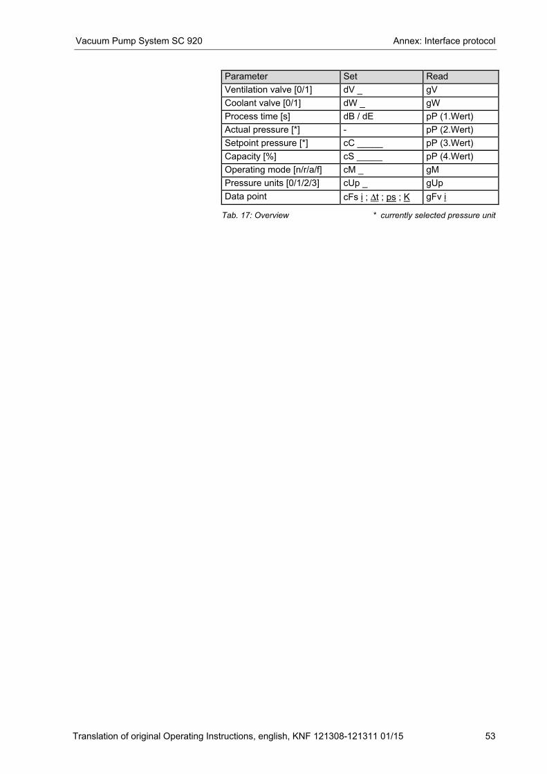
Vacuum Pump System SC 920 Annex: Interface protocol
Translation of original Operating Instructions, english, KNF 121308-121311 01/15 53
Parameter Set Read
Ventilation valve [0/1] dV _ gV
Coolant valve [0/1] dW _ gW
Process time [s] dB / dE pP (1.Wert)
Actual pressure [*] - pP (2.Wert)
Setpoint pressure [*] cC _____ pP (3.Wert)
Capacity [%] cS _____ pP (4.Wert)
Operating mode [n/r/a/f] cM _ gM
Pressure units [0/1/2/3] cUp _ gUp
Data point cFs i ; ∆t ; ps ; K gFv i Tab. 17: Overview * currently selected pressure unit


KNF worldwide Find your local KNF partner on www.knf.com


![PLACAS DE MATRICULA [Modo de compatibilidad]...6,90 € HIDAUTO MOTOR S LHIDAUTO MOTOR S.L. – RECAMBIOS- TELEFONOS: 920 252971 Y 920 352014TELEFONOS: 920 252971 Y 920 352014 PLACA](https://img.pdfslide.net/doc/110x75/6038adc052267f7f546d5464/placas-de-matricula-modo-de-compatibilidad-690-a-hidauto-motor-s-lhidauto.jpg)