Embed Size (px)
Citation preview
Pertanika J. Sci. & Technol. 26 (3): 1465 - 1480 (2018)
SCIENCE & TECHNOLOGYJournal homepage: http://www.pertanika.upm.edu.my/
ISSN: 0128-7680 © 2018 Universiti Putra Malaysia Press.
ARTICLE INFO
Article history:Received: 20 November 2017Accepted: 28 June 2018
E-mail addresses: [email protected] (Arifa Bhutto)[email protected] (Dil Muhammad Akbar Hussain)*Corresponding Author
Validate UML Model and OCL Expressions Using USE Tool
Arifa Bhutto* and Dil Muhammad Akbar HussainDepartment of Energy and Technology, Aalborg University, Esbjerg, Denmark
ABSTRACT
Verification and validation of system models at design level has a huge impact on the quality of the system software engineering process. In general, system modeling and designing Unified Modelling Language (UML) is a standard for the design models of the systems. However, verification and validation of UML models at early design level is not available, but somehow Object Constraint Language (OCL) constraints are defined at the class level to ensure that the model is correctly designed. As for the static–dynamic structure, there is no such mechanism defined in UML/OCL that has a huge impact on the development of the software. Our research is focused on providing verifiable UML/OCL models. Our approach using UML-based Specification Environment (USE) for UML class model is integrated with the OCL constraints to check if the model is correctly designed as well as constraints for verification and validation. In USE, the output is shown as the verifiable UML/OCL models by visual graphical models.
Keywords: OCL constraints, static and dynamic, Unified Modelling Language (UML) and Object Constraints Language (OCL), verification and validation
INTRODUCTION
Unified Modelling Language (UML) is the co-stander for development of the software engineering system. UML is based on different models which are described at
different levels of abstraction of the system. However, in UML models for verification, various types of languages are integrated to make sure the model is correctly designed and developed; among them Object Constraint Language (OCL) is used for the verification and validation of static and dynamic properties of the design models defined by Richters and Gogolla(2002), for further model-driven approaches discussed by Dang and Gogolla (2009).
However, there are various tools designed for the verification and validation of the UML/OCL, like OCL constraints solver for UML/OCL that defines the Java API for the class
Arifa Bhutto and Dil Muhammad Akbar Hussain
1466 Pertanika J. Sci. & Technol. 26 (3): 1465 - 1480 (2018)
model using java programming for verification of OCL expression and satisfying the model condition defined by Ali, Iqbal, Arcuri and Briand (2011). UML2Alloy, another project started in 2005, is a scientific approach to use two critical functionalities of the Alloy Analyser to simulate and verification of the UML class diagram contained OCL constraints to ensure that the properties of the model are satisfied by Anastasakis, Bordbar, Georg and Ray (2007), and Cabot, Clarisó and Riera (2014).
UMLtoCSP (Cabot, Clarisó, & Riera, 2007) is a tool for automatic verification of UML models with OCL constraints. The model checks correctness for properties of the models. UMLtoCSP tool checks for satisfiability and contradictory constraints. It supports only UML class diagrams and shows a graphical view of the system (Cabot et al., 2007).
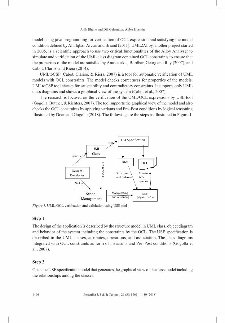
The research is focused on the verification of the UML/OCL expressions by USE tool (Gogolla, Büttner, & Richters, 2007). The tool supports the graphical view of the model and also checks the OCL constraints by applying variants and Pre–Post conditions by logical reasoning illustrated by Doan and Gogolla (2018). The following are the steps as illustrated in Figure 1.
Figure 1. UML/OCL verification and validation using USE tool
Step1
The design of the application is described by the structure model in UML class, object
diagram and behavior of the system including the constraints by the OCL. The USE
specification is described in the UML classes, attributes, operations, and association. The
class diagrams integrated with OCL constraints as form of invariants and Pre–Post conditions
(Gogolla et al.,2007).
Step2
Open the USE specification model that generates the graphical view of the class model
including the relationships among the classes.
Step3
Check if the model structure is correct, then USE will verify behavioral properties of the
system model by analyzing the object diagram, which generates the sequence diagram in
connection.
Step4
Figure 1. UML/OCL verification and validation using USE tool
Step 1
The design of the application is described by the structure model in UML class, object diagram and behavior of the system including the constraints by the OCL. The USE specification is described in the UML classes, attributes, operations, and association. The class diagrams integrated with OCL constraints as form of invariants and Pre–Post conditions (Gogolla et al., 2007).
Step 2
Open the USE specification model that generates the graphical view of the class model including the relationships among the classes.
Validate UML Model and OCL Expressions using USE Tool
1467Pertanika J. Sci. & Technol. 26 (3): 1465 - 1480 (2018)
Step 3
Check if the model structure is correct, then USE will verify behavioral properties of the system model by analyzing the object diagram, which generates the sequence diagram in connection.
Step 4
The USE model checks the UML class diagram relations, OCL constraints, invariants, and Pre–Post condition to make sure that all OCL constraints are applied correctly and respond to the violation of the constraints as form of the error detected.
In section II, we will further discuss the aforementioned steps in a detailed case study.
CASE STUDY
This section describes the small application model to check and verify the designed approach by using the UML 2.2 and USE tool. The School Management System (SMS) is a complete framework for the management of the school. The main functions of the application are the following models:
• Student admission module
• Class distribution and timetable module
• Employee management module
• Payroll management module
• Accounts management module
• Generating reports
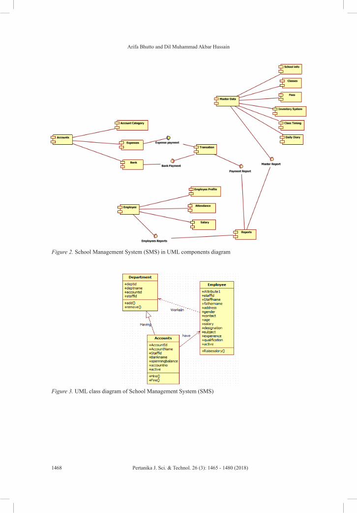
However, the detailed design of all model components of SMS is shown in Figure 2.
VERIFYING METHODOLOGY
Consider the aforementioned study first; we design the component diagram of the case study using UML in Figure 2 and it represents the SMS requirement models of the case study in detail. The internal structure of the components model is based on the object class structure, therefore we design the class structure of the SMS case study using UML, shown in Figure 3. According to the real requirements, class diagrams represent the entities, data types, functionalities, and relationships of various entities. In UML, class structure shows the data types, operations, and relationships. Using the example of our case study, we developed the models describing employees, departments, accounts, with attributes, operations, and relationships of the classes as shown in Figure 3. Furthermore, we integrated the class diagram with OCL constraints, which we described in the natural language. Using OCL language, these constraints are integrated with the UML class diagrams.
Arifa Bhutto and Dil Muhammad Akbar Hussain
1468 Pertanika J. Sci. & Technol. 26 (3): 1465 - 1480 (2018)
Figure 2. School Management System (SMS) in UML components diagram
Figure 2. School Management System (SMS) in UML
components diagram
Figure 3. UML class diagram of School Management System (SMS) Figure 3. UML class diagram of School Management System (SMS)
Validate UML Model and OCL Expressions using USE Tool
1469Pertanika J. Sci. & Technol. 26 (3): 1465 - 1480 (2018)
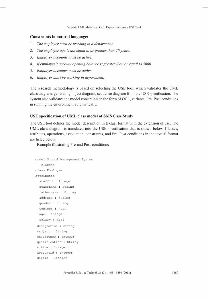
Constraints in natural language:
1. The employer must be working in a department.
2. The employer age is not equal to or greater than 20 years.
3. Employer accounts must be active.
4. If employee’s account opening balance is greater than or equal to 5000.
5. Employer accounts must be active.
6. Employer must be working in department.
The research methodology is based on selecting the USE tool, which validates the UML class diagram, generating object diagram, sequence diagram from the USE specification. The system also validates the model constraints in the form of OCL, variants, Pre–Post conditions in running the environment automatically.
USE specification of UML class model of SMS Case Study
The USE tool defines the model description in textual format with the extension of use. The UML class diagram is translated into the USE specification that is shown below. Classes, attributes, operations, association, constraints, and Pre–Post conditions in the textual format are listed below:-- Example illustrating Pre-and Post-conditions
Constraints in natural language:
1. The employer must be working in a department.
2. The employer age is not equal to or greater than 20 years.
3. Employer accounts must be active.
4. If employee’s account opening balance is greater than or equal to 5000.
5. Employer accounts must be active.
6. Employer must be working in department.
The research methodology is based on selecting the USE tool, which validates the UML
class diagram, generating object diagram, sequence diagram from the USE specification. The
system also validates the model constraints in the form of OCL, variants, Pre–Post conditions
in running the environment automatically.
USE specification of UML class model of SMS Case Study
The USE tool defines the model description in textual format with the extension of use. The
UML class diagram is translated into the USE specification that is shown below. Classes,
attributes, operations, association, constraints, and Pre–Post conditions in the textual format
are listed below:
-- Example illustrating Pre-and Post-conditions
model School_Management_System
-- classes
class Employee
attributes
staffid : Integer
staffname : String
fathername : String
address : String
gender : String
contect : Real
age : Integer
salary : Real
designation : String
subject : String
experience : Integer
qualification : String
active : Integer
accountid : Integer
deptid : Integer
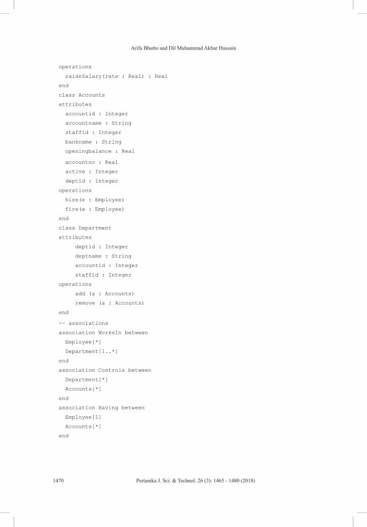
operations
raiseSalary(rate : Real) : Real
end
class Accounts
attributes
accountid : Integer
accountname : String
staffid : Integer
bankname : String
openingbalance : Real
accountno : Real
active : Integer
deptid : Integer
operations
hire(e : Employee)
fire(e : Employee)
end
class Department
attributes
deptid : Integer
deptname : String
accountid : Integer
staffid : Integer
operations
add (a : Accounts)
remove (a : Accounts)
end
Arifa Bhutto and Dil Muhammad Akbar Hussain
1470 Pertanika J. Sci. & Technol. 26 (3): 1465 - 1480 (2018)
designation : String
subject : String
experience : Integer
qualification : String
active : Integer
accountid : Integer
deptid : Integer
operations
raiseSalary(rate : Real) : Real
end
class Accounts
attributes
accountid : Integer
accountname : String
staffid : Integer
bankname : String
openingbalance : Real
accountno : Real
active : Integer
deptid : Integer
operations
hire(e : Employee)
fire(e : Employee)
end
class Department
attributes
deptid : Integer
deptname : String
accountid : Integer
staffid : Integer
operations
add (a : Accounts)
remove (a : Accounts)
end
-- associations
association WorksIn between
Employee[*]
Department[1..*]
end
association Controls between
Department[*]
Accounts[*]
end
association Having between
Employee[1]
Accounts[*]
end
-- constraints
constraints
context Employee inv:
age >= 20
context Department inv:
staffid = 1
context Accounts inv:
accountid=active
context Accounts inv:
openingbalance >= 5000
context Employee inv:
staffid = deptid
context Accounts inv:
staffid= accountid
context Employee::raiseSalary(rate : Real) : Real
post raiseSalaryPost:
designation : String
subject : String
experience : Integer
qualification : String
active : Integer
accountid : Integer
deptid : Integer
operations
raiseSalary(rate : Real) : Real
end
class Accounts
attributes
accountid : Integer
accountname : String
staffid : Integer
bankname : String
openingbalance : Real
accountno : Real
active : Integer
deptid : Integer
operations
hire(e : Employee)
fire(e : Employee)
end
class Department
attributes
deptid : Integer
deptname : String
accountid : Integer
staffid : Integer
operations
add (a : Accounts)
remove (a : Accounts)
end
Validate UML Model and OCL Expressions using USE Tool
1471Pertanika J. Sci. & Technol. 26 (3): 1465 - 1480 (2018)
-- associations
association WorksIn between
Employee[*]
Department[1..*]
end
association Controls between
Department[*]
Accounts[*]
end
association Having between
Employee[1]
Accounts[*]
end
-- constraints
constraints
context Employee inv:
age >= 20
context Department inv:
staffid = 1
context Accounts inv:
accountid=active
context Accounts inv:
openingbalance >= 5000
context Employee inv:
staffid = deptid
context Accounts inv:
staffid= accountid
context Employee::raiseSalary(rate : Real) : Real
post raiseSalaryPost:
salary = salary@pre * (1.0 + rate)
post resultPost:
result = salary
context Accounts::hire(e : Employee)
pre hirePre1: e.isDefined()
pre hirePre2: employee->excludes(e)
post hirePost: employee->includes(e)
context Accounts::fire(e : Employee)
pre firePre: employee->includes(e)
post firePost: employee->excludes(e)
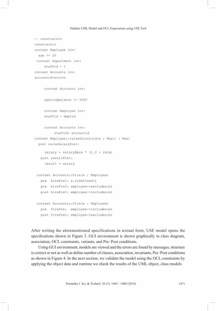
After writing the aforementioned specifications in textual form, USE model opens the
specifications shown in Figure 3. GUI environment is shown graphically in class diagram,
association, OCL constraints, variants, and Pre–Post conditions.
Using GUI environment, models are viewed and the errors are found by messages, structure
is correct or not as well as define number of classes, association, invariants, Pre–Post
conditions as shown in Figure 3. In the next section, we validate the model using the OCL
constraints by applying the object data and runtime we check the results of the UML object,
class models
After writing the aforementioned specifications in textual form, USE model opens the specifications shown in Figure 3. GUI environment is shown graphically in class diagram, association, OCL constraints, variants, and Pre–Post conditions.
Using GUI environment, models are viewed and the errors are found by messages, structure is correct or not as well as define number of classes, association, invariants, Pre–Post conditions as shown in Figure 4. In the next section, we validate the model using the OCL constraints by applying the object data and runtime we check the results of the UML object, class models
-- associations
association WorksIn between
Employee[*]
Department[1..*]
end
association Controls between
Department[*]
Accounts[*]
end
association Having between
Employee[1]
Accounts[*]
end
-- constraints
constraints
context Employee inv:
age >= 20
context Department inv:
staffid = 1
context Accounts inv:
accountid=active
context Accounts inv:
openingbalance >= 5000
context Employee inv:
staffid = deptid
context Accounts inv:
staffid= accountid
context Employee::raiseSalary(rate : Real) : Real
post raiseSalaryPost:
Arifa Bhutto and Dil Muhammad Akbar Hussain
1472 Pertanika J. Sci. & Technol. 26 (3): 1465 - 1480 (2018)
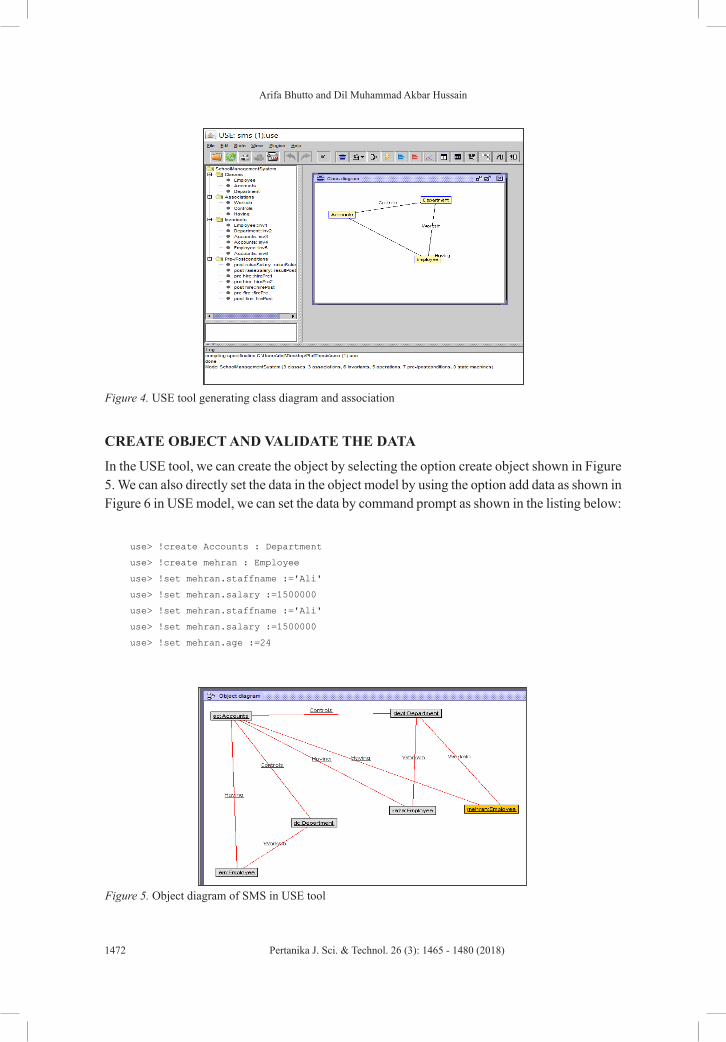
CREATE OBJECT AND VALIDATE THE DATA
In the USE tool, we can create the object by selecting the option create object shown in Figure 5. We can also directly set the data in the object model by using the option add data as shown in Figure 6 in USE model, we can set the data by command prompt as shown in the listing below:
Figure 3. USE tool generating class diagram and association
CREATE OBJECT AND VALIDATE THE DATA
In the USE tool, we can create the object by selecting the option create object shown in
Figure 4. We can also directly set the data in the object model by using the option add data as
shown in Figure 5 in USE model, we can set the data by command prompt as shown in the
listing below: use> !create Accounts : Department
use> !create mehran : Employee
use> !set mehran.staffname :='Ali'
use> !set mehran.salary :=1500000
use> !set mehran.staffname :='Ali'
use> !set mehran.salary :=1500000
use> !set mehran.age :=24
Figure 4. USE tool generating class diagram and association
Figure 3. USE tool generating class diagram and association
CREATE OBJECT AND VALIDATE THE DATA
In the USE tool, we can create the object by selecting the option create object shown in
Figure 4. We can also directly set the data in the object model by using the option add data as
shown in Figure 5 in USE model, we can set the data by command prompt as shown in the
listing below: use> !create Accounts : Department
use> !create mehran : Employee
use> !set mehran.staffname :='Ali'
use> !set mehran.salary :=1500000
use> !set mehran.staffname :='Ali'
use> !set mehran.salary :=1500000
use> !set mehran.age :=24
Figure 4. Object diagram of SMS in USE tool
Figure 5. Class, object diagram with data, and properties of the objects
Figure 5. Object diagram of SMS in USE tool
Validate UML Model and OCL Expressions using USE Tool
1473Pertanika J. Sci. & Technol. 26 (3): 1465 - 1480 (2018)
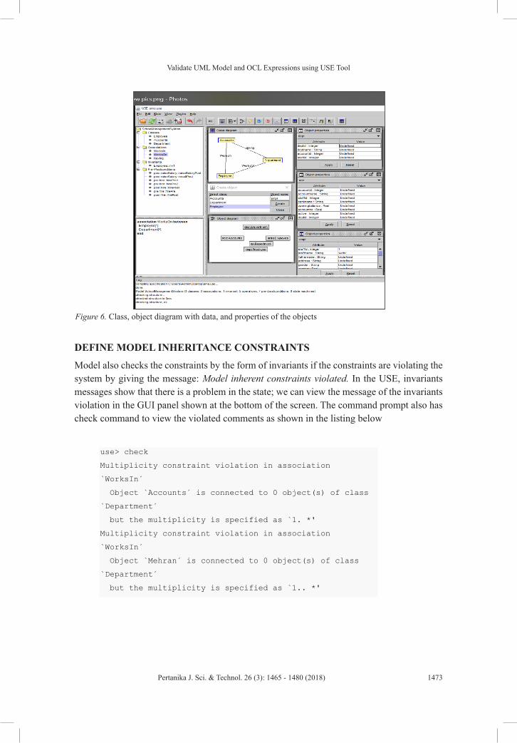
DEFINE MODEL INHERITANCE CONSTRAINTS
Model also checks the constraints by the form of invariants if the constraints are violating the system by giving the message: Model inherent constraints violated. In the USE, invariants messages show that there is a problem in the state; we can view the message of the invariants violation in the GUI panel shown at the bottom of the screen. The command prompt also has check command to view the violated comments as shown in the listing below
Figure 4. Object diagram of SMS in USE tool
Figure 5. Class, object diagram with data, and properties of the objects Figure 6. Class, object diagram with data, and properties of the objects
DEFINE MODEL INHERITANCE CONSTRAINTS
Model also checks the constraints by the form of invariants if the constraints are violating the
system by giving the message: Model inherent constraints violated. In the USE, invariants
messages show that there is a problem in the state; we can view the message of the invariants
violation in the GUI panel shown at the bottom of the screen. The command prompt also has
check command to view the violated comments as shown in the listing below use> check
Multiplicity constraint violation in association
`WorksIn´
Object `Accounts´ is connected to 0 object(s) of class
`Department´
but the multiplicity is specified as `1. *'
Multiplicity constraint violation in association
`WorksIn´
Object `Mehran´ is connected to 0 object(s) of class
`Department´
but the multiplicity is specified as `1.. *'
According to the above class diagram in UML, it is specified that each employee works in the
department. USE GUI model shows the object diagram; there is no employee who works in
the department in association link. We can fix this in GUI model as well as by command
prompt by just typing the insert command for inserting the missing association listed below:
use>!insert (mehran, Accounts) into worksIn
The USE GUI environment connected the link directly by inserting the object using the
object diagram option or inserting the command directly from the command prompt.
The USE diagram, Figure 6, shows the red link in the object diagram between department
and employee object, which is the violation of invariants; we can fix it by applying the
correct rules for invariants, which is shown in Figure 7 of the model diagrams using USE
GUI.
Arifa Bhutto and Dil Muhammad Akbar Hussain
1474 Pertanika J. Sci. & Technol. 26 (3): 1465 - 1480 (2018)
According to the above class diagram in UML, it is specified that each employee works in the department. USE GUI model shows the object diagram; there is no employee who works in the department in association link. We can fix this in GUI model as well as by command prompt by just typing the insert command for inserting the missing association listed below:
DEFINE MODEL INHERITANCE CONSTRAINTS
Model also checks the constraints by the form of invariants if the constraints are violating the
system by giving the message: Model inherent constraints violated. In the USE, invariants
messages show that there is a problem in the state; we can view the message of the invariants
violation in the GUI panel shown at the bottom of the screen. The command prompt also has
check command to view the violated comments as shown in the listing below use> check
Multiplicity constraint violation in association
`WorksIn´
Object `Accounts´ is connected to 0 object(s) of class
`Department´
but the multiplicity is specified as `1. *'
Multiplicity constraint violation in association
`WorksIn´
Object `Mehran´ is connected to 0 object(s) of class
`Department´
but the multiplicity is specified as `1.. *'
According to the above class diagram in UML, it is specified that each employee works in the
department. USE GUI model shows the object diagram; there is no employee who works in
the department in association link. We can fix this in GUI model as well as by command
prompt by just typing the insert command for inserting the missing association listed below:
use>!insert (mehran, Accounts) into worksIn
The USE GUI environment connected the link directly by inserting the object using the
object diagram option or inserting the command directly from the command prompt.
The USE diagram, Figure 6, shows the red link in the object diagram between department
and employee object, which is the violation of invariants; we can fix it by applying the
correct rules for invariants, which is shown in Figure 7 of the model diagrams using USE
GUI.
The USE GUI environment connected the link directly by inserting the object using the object diagram option or inserting the command directly from the command prompt.
The USE diagram, Figure 7, shows the red link in the object diagram between department and employee object, which is the violation of invariants; we can fix it by applying the correct rules for invariants, which is shown in Figure 8 of the model diagrams using USE GUI.
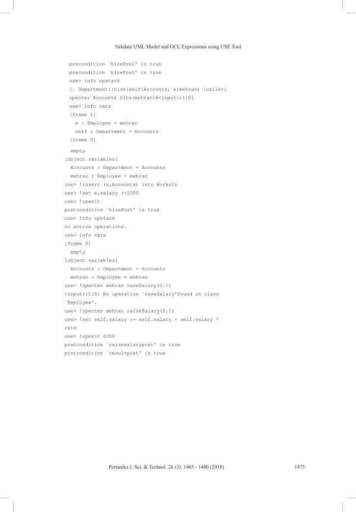
METHOD FOR CHECKING INVARIANTS
Checking class invariants automatically, the USE graphical interface has a capability to view the changes directly. We can change the status and the GUI shows the results. OCL invariants can be analyzed by applying the commands listed below:
METHOD FOR CHECKING INVARIANTS
Checking class invariants automatically, the USE graphical interface has a capability to view
the changes directly. We can change the status and the GUI shows the results. OCL invariants
can be analyzed by applying the commands listed below: Department::hire(self:Accounts, e:mehran) [caller:
openter Accounts hire(mehran)@<input>:1:0]
use> info vars
[frame 1]
e : Employee = mehran
self : Department = Accounts
[frame 0]
empty
[object variables]
Accounts : Department = Accounts
mehran : Employee = mehran
use> !insert (e,Accounts) into WorksIn
use> !openter mehran raiseSalary(0.1)
use> !set self.salary := self.salary+ self.salary * rate
use> !create Accounts : Department
use> !create mehran : Employee
use> !set mehran.staffname :='Ali'
use> !set mehran.age :=24
use> !openter Accounts hire(mehran)
precondition `hirePre1' is true
precondition `hirePre2' is true
use> info opstack
1. Department::hire(self:Accounts, e:mehran) [caller:
openter Accounts hire(mehran)@<input>:1:0]
use> info vars
[frame 1]
e : Employee = mehran
self : Department = Accounts
[frame 0]
Validate UML Model and OCL Expressions using USE Tool
1475Pertanika J. Sci. & Technol. 26 (3): 1465 - 1480 (2018)
METHOD FOR CHECKING INVARIANTS
Checking class invariants automatically, the USE graphical interface has a capability to view
the changes directly. We can change the status and the GUI shows the results. OCL invariants
can be analyzed by applying the commands listed below: Department::hire(self:Accounts, e:mehran) [caller:
openter Accounts hire(mehran)@<input>:1:0]
use> info vars
[frame 1]
e : Employee = mehran
self : Department = Accounts
[frame 0]
empty
[object variables]
Accounts : Department = Accounts
mehran : Employee = mehran
use> !insert (e,Accounts) into WorksIn
use> !openter mehran raiseSalary(0.1)
use> !set self.salary := self.salary+ self.salary * rate
use> !create Accounts : Department
use> !create mehran : Employee
use> !set mehran.staffname :='Ali'
use> !set mehran.age :=24
use> !openter Accounts hire(mehran)
precondition `hirePre1' is true
precondition `hirePre2' is true
use> info opstack
1. Department::hire(self:Accounts, e:mehran) [caller:
openter Accounts hire(mehran)@<input>:1:0]
use> info vars
[frame 1]
e : Employee = mehran
self : Department = Accounts
[frame 0]
empty
[object variables]
Accounts : Department = Accounts
mehran : Employee = mehran
use> !insert (e,Accounts) into WorksIn
use> !set e.salary :=2000
use> !opexit
postcondition `hirePost' is true
use> info opstack
no active operations.
use> info vars
[frame 0]
empty
[object variables]
Accounts : Department = Accounts
mehran : Employee = mehran
use> !openter mehran raseSalary(0.1)
<input>:1:0: No operation `raseSalary'found in class
`Employee'.
use> !openter mehran raiseSalary(0.1)
use> !set self.salary := self.salary + self.salary *
rate
use> !opexit 2200
postcondition `raisesalarypost' is true
postcondition `resultpost' is true
DISCUSSION
The results of the design model shown by the USE GUI generate the sequence diagram to
visualize the variants, Pre–Post conditions by directly applying an object to validate the
model according to the data. In Figures 8 and 9, communication model represents the object
data including the actual data and relationships of the objects. Figure 10 shows the object,
class variants, and counts how many objects are defined as well as class invariants checked-
the invariants view of the class by green check that all invariants are correct. Figure 11 shows
Arifa Bhutto and Dil Muhammad Akbar Hussain
1476 Pertanika J. Sci. & Technol. 26 (3): 1465 - 1480 (2018)
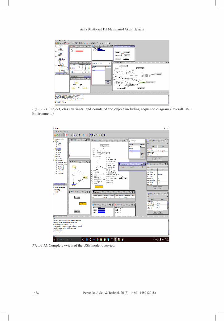
DISCUSSION
The results of the design model shown by the USE GUI generate the sequence diagram to visualize the variants, Pre–Post conditions by directly applying an object to validate the model according to the data. In Figures 9 and 10, communication model represents the object data including the actual data and relationships of the objects. Figure 11 shows the object, class variants, and counts how many objects are defined as well as class invariants checked- the invariants view of the class by green check that all invariants are correct. Figure 12 shows the complete model behavior and all sub-models like state shows the model status, communication, object, class, class invariants, and sequence. The model output shows that the verification and validation process of the school management system design is done correctly by UML/OCL constraints applied on object class models.
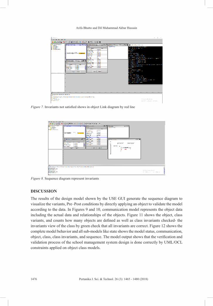
Figure 6. Invariants not satisfied shows in object Link diagram by red line
Figure 7. Sequence diagram represent invariants
Figure 7. Invariants not satisfied shows in object Link diagram by red lineFigure 6. Invariants not satisfied shows in object Link diagram by red line
Figure 7. Sequence diagram represent invariants Figure 8. Sequence diagram represent invariants
Validate UML Model and OCL Expressions using USE Tool
1477Pertanika J. Sci. & Technol. 26 (3): 1465 - 1480 (2018)
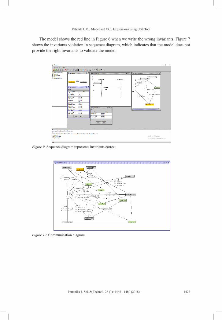
Figure 8. Sequence diagram represents invariants correct
Figure 9. Sequence diagram represents invariants correct
Figure 10. Object, class variants, and counts of the object including sequence diagram( Overall USE Environment )
Figure 9. Communication diagram
Figure 10. Communication diagram
The model shows the red line in Figure 6 when we write the wrong invariants. Figure 7 shows the invariants violation in sequence diagram, which indicates that the model does not provide the right invariants to validate the model.
Arifa Bhutto and Dil Muhammad Akbar Hussain
1478 Pertanika J. Sci. & Technol. 26 (3): 1465 - 1480 (2018)
Figure 10. Object, class variants, and counts of the object including sequence diagram( Overall USE Environment )
Figure 9. Communication diagram
Figure 11. Object, class variants, and counts of the object including sequence diagram (Overall USE Environment )
Figure 11. Complete vview of the USE model overview
Figure 12. Complete vview of the USE model overview
Validate UML Model and OCL Expressions using USE Tool
1479Pertanika J. Sci. & Technol. 26 (3): 1465 - 1480 (2018)
CONCLUSION
This paper is an approach for verification and validation of structural and behavioral properties of UML model integrated with the OCL constraints. The input we select is USE application that describes the class structure and applies the OCL constraints as a form of invariants. As an output, we found the verifiable UML class, object, and sequence model. We apply this methodology on the small case, which shows very impressive results for the verification and validation of UML models.
Our future work will continue in different directions, like all the models are generated automatically and adding the frame conditions to UML and OCL models.
ACKNOWLEDGEMENT
This research work was conducted and supported by the Department of Energy and Technology, Aalborg University, Denmark. Authors greatly acknowledge and appreciate their excellent unconditional support for using laboratories and other facilities. Special thanks to Jens Bo, Head of the Section at Esbjerg Campus for his constant involvement in keeping the status updated with short seminar/presentations.
REFERENCESAli, S., Iqbal, M. Z., Arcuri, A., & Briand, L. (2011, July). A search-based OCL constraint solver for
model-based test data generation. In 11th International Conference on Quality Software (QSIC), 2011 (pp. 41–50). IEEE.
Anastasakis, K., Bordbar, B., Georg, G., & Ray, I. (2007, September). UML2Alloy: A challenging model transformation. In International Conference on Model Driven Engineering Languages and Systems (pp. 436–450). Springer, Berlin, Heidelberg.
Cabot, J., Clarisó, R., & Riera, D. (2007, November). UMLtoCSP: A tool for the formal verification of UML/OCL models using constraint programming. In Proceedings of the Twenty-Second IEEE/ACM International Conference on Automated Software Engineering (pp. 547–548). ACM.
Cabot, J., Clarisó, R., & Riera, D. (2014). On the verification of UML/OCL class diagrams using constraint programming. Journal of Systems and Software, 93, 1–23.
Dang, D., & Gogolla M., (2009). Precise model-driven transformations based on graphs and met models. In 7th IEEE International Conference on Software Engineering and Formal Methods (pp. 23–27). IEEE.
Doan, K. H., & Gogolla, M. (2018). Logical reasoning with object diagrams in a UML and OCL tool. In P. Chapman, A. Moktefi, & G. Stapleton, (Eds.), Proceedings of the 10th International Conference on Diagrams (DIAGRAMS 2018). Springer, LNCS, Berlin, Heidelberg.
Gogolla, M., Büttner, F., & Richters, M. (2007). USE: A UML-based specification environment for validating UML and OCL. Science of Computer Programming, 69(1–3), 27–34.
Richters, M., & Gogolla, M. (2002). OCL: Syntax, semantics, and tools. In Object Modelling with the OCL (pp. 42–68). Springer, Berlin, Heidelberg.