Embed Size (px)
Citation preview

Validation of a vibration and electric modelof honeycomb panels equiped withpiezoelectric patch actuators
Etienne Balmes* — Corine Florens**
* Arts et Metiers ParisTech (LMSP)151 Bld de l’Hopital, 75013 Paris
** ONERA DADS, 92322 Chatillon CedexEcole Centrale Paris, MSSMat, 92295 Chatenay Malabry
ABSTRACT.Active control has often been considered for low frequency noise control of aircraft orhelicopter trim panels. The present study proposes a methodology for numerical homogeneiza-tion of honeycombs and shell models of piezoelectric patches. These models are validatedexperimentally. The considered honeycomb is shown to be significantly viscoelastic and localbending effects are shown to limit achievable active control performance. Finally modelingstrategies for the integration of the model in a numerical design process are discussed.
RÉSUMÉ.Le contrôle actif à souvent été considéré pour la maitrise du bruit basse fréquence despanneaux d’habillage des avions et hélicoptères. Dans le cas de panneaux en nid d’abeille, lesrésultats n’ont pas toujours été à la hauteur des attentes. L’étude présentée introduit un modèledétaillé de panneau en nid d’abeille équipé de patchs piézoélectriques et valide ce modèle expé-rimentalement. L’utilisation de modes périodiques permet une analyse détaillée de l’influencedes constituants dans le comportement vibratoire du nid d’abeille. Les effets viscoélastiquesprésents pour le Nomex sont par ailleurs mis en évidence. Du point de vue électrique, on montreque la flexibilité résiduelle induit une cloque, flexion très localisée des peaux. La performanceatteignable par le contrôle actif est donc limitée. Finalement, des stratégies pour l’intégrationdu modèle proposé dans un processus de conception sont discutées.
KEYWORDS:active control/ honeycomb/ test-analysis correlation
MOTS-CLÉS :contrôle actif/ nid d’abeille/ corrélation calcul-essai
RCMA. Volume 00 – n˚0/2009, pages 1 à 15

2 RCMA. Volume 00 – n˚0/2009
1. Introduction
Reduction of noise transmission inside cabins, for improved passenger comfort, isan important concern for the aircraft industry. Usually trim panels are made of hon-eycomb sandwich composite. Those panels have a high strength to weight ratio, butacoustical properties have to be improved by complementary treatments. Passive treat-ments are efficient for high frequencies. Active sound and vibration control is oftenconsidered as a solution to reduce residual noise for low and medium frequencies.
While active control of honeycomb panels has been the object of various stud-ies (Bihanet al., Avril 2005), detailed modeling of the panels equipped with piezo-electric patches was not performed. In general, such modeling seems necessary toachieve a consistent design methodology and was thus the general objective of thisstudy.
Section 2 discusses honeycomb modeling using the classical assembly of threemodels : two skins, modeled as composite plates, and a core, modeled as an equiv-alent orthotropic volume. A numerical homogeneization methodology based on thecorrelation of periodic bending mode frequencies is introduced to evaluate the effec-tive parameters of the orthotropic material. This methodology is then used to analyzefactors influencing the effective parameters.
Section 3 introduces a piezoelectric shell element and discusses methodologies fornumerical resolution of the coupled mechanical/electrical problem.
Experimental validations of the proposed models are discussed in section 4. TheNomex honeycomb considered in the test is shown to be significantly viscoelastic.The identified frequency dependent constitutive law is sufficient to accurately predicttransfers of the active panel. Local bending effects in the honeycomb skins are thenstudied in detail since they are a factor limiting the performance that can be achievedin active control.
Finally section 5 discusses practical constraints linked to the use of the proposedmodel in a design phase.
2. Models of honeycomb panels
2.1. Equivalent models
When modeling honeycomb panels, the use of detailed 3D models where each ofthe walls of the honeycomb is modeled can rapidly become inaccessible. The classicalapproach is thus to build an equivalent representation with skins modeled as shellsand the honeycomb modeled using an orthotropic volume. A wide range of equivalentformulas giving the effective properties of the orthotropic material as function of thecell properties can be found in the literature (Gibsonet al., 1997; Grédiac, 1993; Nooret al., 1997; Hoheet al., 2001).

Honeycomb and piezo actuator model 3
The first objective of the present work is to propose a systematic approach to eval-uate the effective (or equivalent) properties based on a detailed FE model of the hon-eycomb.
To demonstrate the approach, one considers the mesh shown left in figure 1. Thismodel is meant to represent physical reality (geometry, thickness of various walls,material...) as closely as possible, with the intention of minimizing the modelingerrors. It will be used as reference to estimate honeycomb properties starting frommaterial and geometric considerations.
�W �L
�F�a�c�e� �s�h�e�e�t
�H�o�n�e�y�c�o�m�b�
�A�d�h�e�s�i�v�e�Shell elements
�Double thickness wall�Simple thickness wall
�Shell elements
�Shell elements
Figure 1. Honeycomb representative volume. Left : Detailed 3D model (3D). Right :shell volume shell model (SVS)
The geometry of the glue is shown in figure 2. Rather than introducing a detailedgeometry, the 3D model, considered here, privileges a functionally equivalent repre-sentation as a small plate extending from the skin neutral fiber to its surface. Theexplicit representation of glue elements thus allows a meshing of the honeycomb cellwalls and face-sheets that is compatible and strictly respects the geometry. Functionalvalues of shear and bending stiffness can then be easily related to the glue modulusEg and shell element thicknesstg.
Figure 2. Modeling of adhesive fillet.
The classical equivalent model for large panels uses the shell/volume/shell (SVS)layout shown right in figure 1. The sandwich face sheets are modeled by isotropic

4 RCMA. Volume 00 – n˚0/2009
shell, for metallic skin such as aluminum, or multilayered composite laminate, forcomposite skin such as carbon fiber reinforced composites. As in most of the litera-ture, Mindlin formulations and Classical Laminated Plate Theory (Jones, 1975; Berth-elot, 1992) is assumed to be sufficient. For the simulations shown, the SDT (Balmeset al., 2007) implementation of MITC4 composite plate/shell elements with shear cor-rection is used. To simplify handling, the face sheets are normally meshed to becompatible with the underlying core models. In the case of detailed 3D models, onethus uses hexagonal shapes composed of two quadrangular elements, while in the SVSmodel regular rectangles are used.
2.2. Determination of effective parameters using periodic modes
Homogeneization techniques determine effective properties of the homogenizedmodel by comparing various properties (static deflections, strain energies for partic-ular deformations, ...). The approach retained here is to compare the frequencies ofbending modes obtained with periodicity conditions that are equivalent for both mod-els shown in figure 1 and to update the effective parameters of the SVS model tomatch the frequencies of the detailed 3D model. This is a numerical homogeneizationprocedure since one uses a detailed 3D FEM model as reference and a SVS model todetermine the effective parameters. The update can be performed for all wavelengthsand the range of stability of the parameter is a useful result of the study.
While periodic modes can be computed using a long beam sample and simple con-ditions of equal displacement at the wavelength (Florenset al., 2006), this approachis costly. These modes can however be computed much more efficiently using Fouriertheory as detailed in (Clouteauet al., 2005) for the periodic structures and (Sternchüss,A. and Balmes, E. and Jean, P. and Lombard, JP., 2008) for cyclic symmetry.
This section summarizes the theory underlying periodic mode computations. Oneconsiders a model whose properties are spatially periodic. For a physical response,known at regularly spaced positionsn∆x, one can compute its Fourier transform
U(κ) =+∞∑
n=−∞u(n∆x)e−jκn∆x [1]
U(κ) is a complex shape defined on the mesh of the repeated cell. One actually usestwo cells to represent the real and imaginary parts ofU . The wave numberκ varies inthe [0, 2π
∆x ] interval (or any interval of the same length, sinceU(κ) is periodic in thewavelength domain).
Periodic modes can be shown to be mono-harmonic (to involve a singleU(κ)). Asa result one has
u(n∆x) = Re(U(κ)ejn(κ∆x)
)[2]

Honeycomb and piezo actuator model 5
This property can be used to recover motion on any cell based on known valueson the first one. Using the continuity condition linked to the fact thatuleft(n∆x) =uright((n − 1)∆x) and observation matricescL, cR to extract the edge motion, onecan write[cL]{U(κ)} = [cR]{U(κ)}e−j(κ∆x). Hence in the real/imaginary format,one has the constraint equation on nodes of the cell edge[
[cl]− cos(κ∆x)[cr] − sin(κ∆x)[cr]sin(κ∆x)[cr] [cl]− cos(κ∆x)[cr]
]2Nr×2N
{Re(U)Im(U)
}= 0 [3]
Since periodic modes are mono-harmonic solutions of wavelengthπ/κ, one thussolves for [
K − ω2j M 0
0 K − ω2j M
]{Re(U)Im(U)
}= 0 [4]
with [3] verified. Figure 3 illustrates the basic cell and restitution on multiple cellsusing [2] of modes computed for1/κ equal to 3 and 17.
Figure 3. Periodic modes of the SVS model
2.3. Analysis of properties
For the detailed 3D model of the nominal honeycomb in this study, figure 4 dis-plays the evolution of the periodic mode frequency as a function of wavelength andthe associated energy contributions.A terms refer to membrane/shear effects andDto bending (see (Jones, 1975) and section 3.1)
The plot clearly indicates very different regimes. Above 1000 cell lengths (atlow frequencies), the energy is essentially due membrane effects in the skin. This isunderlying principle of honeycombs; the core only serves to separate the skins whichcarry all the load. Between 3 and 100 cell lengths, the core contains a major part ofthe energy. Its properties are thus critical to properly represent motion with relativelyshort wavelengths.
For very short wavelengths and very high frequencies, one starts seeing localmodes of the skin or local bending of the cell walls. Such modes would be describedas surface waves and are not really of interest to the present study.

6 RCMA. Volume 00 – n˚0/2009
101
102
103
0
0.2
0.4
0.6
0.8
Wavelength/LL
EK F
ract
ion
CoreGlue
A
GlueD
SkinA
SkinD
101
102
103
0
1
2
3
4
5
Wavelength/LL
Fre
q [k
Hz]
Figure 4. Energy contribution of constituents and frequency of longitudinal periodicmodes as a function of wavelength divided by cell lengthLL. Detailed 3D model.
For the parameters of figure 4, the shear energy in the glue is above 8 % in the 10to 50 cell lengths range. Figure 5 illustrates the evolution of energy fractions in theglue layer for varying glue moduli. Since 0.2 GPa is a very realistic value for epoxy itclearly appears that the glue can indeed have a major impact on the short wavelengthdynamics.
Figure 5. Energy fraction of constituents. Detailed 3D model with 0.2 to 20 GPa gluemodulus.
Figure 6 shows the same plot for the SVS model. Similar regimes are found andone verifies the classical results that almost all the energy in the core is associated withtheGxz shear.

Honeycomb and piezo actuator model 7
101
102
103
0.2
0.4
0.6
0.8
Wavelength/LL
EK F
ract
ion
SkinCore−otherCore−GxzCore−Gyz
Figure 6. Energy contribution of constituents for first longitudinal periodic mode asa function of wavelength. SVS model.
Figure 7 illustrates the proposed homogeneization procedure. One computes, andshows in the top graph, the frequency error on the corresponding first bending modefor multiple values ofGxz. In the present case, one sees a divergence below5∆x. Thisis associated with the fact that cell wall bending occurs near 10 kHz and becomes thefirst periodic mode for very short wavelengths.
The bottom graph shows the evolution of theGxz value for which the frequencyerror is null. The mean value is 26.94 MPa. The nominal model (top curve) showedan increase of the estimated modulus for large wavelength. Several studies were per-formed to analyze the source of this discrepancy. The skin models clearly have noimpact: a SVS model that has skin elements identical to the 3D model also shows thesame decrease. Eventually, it was found that the density of the core is an extremelyinfluent parameter in this range. This is not unexpected since the core has very lim-ited strain energy and thus significant modulus changes are needed to compensate forsmall frequency errors associated with the mass. The nominal model overestimatesthe mass by1%. The five curves are evenly spaced in the1% to 0% interval. A nearlyconstant modulus is thus found for a0.5% overestimation of the mass.
In practice, honeycomb bonding procedure clearly induces uncertainties in themass much larger than0.5%. The proposed analysis thus motivates the need for ex-periments evaluating the transverse shear for waves in the 30 to 200 cell length range(1500 Hz to 100 Hz).

8 RCMA. Volume 00 – n˚0/2009
101
102
103
−2
0
2
4
6
Wavelength/Lcell
∆f/f
3D%
24 MPa26 MPa28 MPa30 MPa
101
102
103
23
24
25
26
27
28
29
Wavelength/Lcell
G1z
(M
Pa)
26.94 MPa
+1% mass
+0% mass
Figure 7. Top: error on frequency of the first periodic bending mode for various val-ues ofGxz. Bottom: Estimation ofGxz associated with no error. Detailed 3D modelwith 4 by 4 refinement (curves correspond to+1% to 0% mass).
3. Model of piezoelectric patch actuators
3.1. Laminated piezoelectric plates
The piezoelectric plate element, implemented in (Balmeset al., 2007) and consid-ered in this work, is based on Classical Laminated Plate Theory (CLPT (Jones, 1975;Berthelot, 1992)) for the mechanical part and the work of Piefort (Piefort, 2001) forthe piezoelectric coupling.
Figure 8. Left Geometry of an N-layered laminate.Right Particularization for a skinwith a piezoelectric patch

Honeycomb and piezo actuator model 9
The global constitutive equations of piezoelectric Mindlin shell are obtained byintegration over thickness and are expressed in the global coordination system. Thepiezoelectric medium has orthotropic mechanic and electric properties; hence the con-stitutive equations for each layer are related to their orthotropic axes.[RS ]k is thetransformation matrix linking the strain in the global coordinate system to the localone, and[RT ]−1
k = [RS ]Tk is the one linking the stresses in the local coordinate sys-tem to the global one. The coupled plate/piezoelectric equations are thus given by
NMQ...
Dk
...
=
A B 0 · · · ([e]k[Rk
s
])T
B D 0 · · · (zmk[e]k[Rk
s
])T
0 0 H · · · 0 · · ·
...[e]k
[Rk
s
]...
...zmk [e]k
[Rk
s
]...
...0...
. . . 0− εk
hk
0. . .
Sm
κγ...
φk
...
[5]
where the constitutive matrices[A] (membrane) ,[B] (membrane/bending coupling)[D] (bending),[F ] (shear) are those found in classical laminated plate theory (see(Jones, 1975)).
It is assumed that the electric field needs only to be known between electrodes andcan be described by the difference of potentialφk, leading to an assumed electric field~E = − ~gradφ. When this field is applied in the direction~e3, the piezoelectric actuatorPZT extends in the plane (~e1, ~e2). It produces load on the piezoelectric layer (or plyin the CLPT terminology) in the direction~e1 which depends one31 andφ. Because ofthe offset between the mid-plane of the actuator and the mid-plane of the multilayerlaminate, the force induces both membrane and bending loads as will be illustrated insection 4.
In the software implementation, the composite plate is modeled using a classicalMITC4 element (Batheet al., 2003). The piezoelectric coupling part of [5] is numeri-cally integrated using the nominal four point rule on the patch. For the electric part, asingle electric DOF is considered for each patch. This DOF is thus common to all el-ements covered by the electrode. In the present configuration two patches are stackedtogether thus leading to a model with two electric DOFs. In practice, the wiring issuch that these potential are equal or opposite. The elimination of this constraint isdone in the model resolution phase.

10 RCMA. Volume 00 – n˚0/2009
3.2. Resolution of system equations
Once assembled the model takes the form
[Zuu Kuφ
Kφu Kφφ
]{qmech
φk
}=
{Fmech
Qk
}[6]
with the classical dynamic stiffnessZ = Ms2 + K. When simulating the response,one needs to consider sensor and actuator configurations.
Piezoelectric patches used as sensors have a charge that remains zero (open circuitmode). One can thus condense the electric DOF. Indeed, one considers an electrostaticbehavior (noMφφ or Mφu) and assumesQk = 0, one thus has
{{qmech}
φk
}=
[I
−[Kφφ]−1[Kφu]
]{q}mech = [T ]{qmech} [7]
This relation can be used to eliminate the electric contribution from the systemequations which become
[T ]T [Z][T ]{qmech} = [T ]T {F} [8]
From this condensation it clearly appears that a patch used as sensor induces a shiftof frequencies form a configuration without piezoelectric coupling.
Piezoelectric patches used as actuators have a difference of potentialφk that isenforced. One can thus use the electric part of [6] to determine the charge
Qk = [Kφu Kφφ]{
qmech
φk
}[9]
and consider the system equations with no piezoelectric coupling and an electric load
Zuuqmech = Fmech −Kuφφk [10]
It clearly appears that the dynamic stiffness of this configuration is that of thepurely mechanical model with no piezoelectric coupling. The modes ofZuu corre-spond to the case withφk set to zero. In other words, the actuator configuration leadsto closed circuit modes.
In the resolution process implemented in (Balmeset al., 2007), electrodes aredeclared to be either open or closed circuit which allows a condensation or elimi-nation of electrical DOFs before computation of modes and static correction for in-puts (Balmes, 1997-2007), which are used to build the state-space model. The inclu-sion of the static correction is shown to be critical in the next section.

Honeycomb and piezo actuator model 11
4. Experimental validation
4.1. Test setup
Multiple modal tests were performed at Ecole Centrale Paris (MSSMat) and KTHStockholm University (MWL). The test beams external dimensions are900 × 45 ×21mm (approximately109 × 5 cells). Configurations with aluminimum and carbonlaminates were tested. The core is a 19 mm thick Nomex paper honeycomb. Thecarbon skin beam was equiped with 3 QuickPack piezoelectric patches detailed infigure 9. Excitation was performed using a shaker or the piezoelectric patches.
Measurements over the full length of the beam were performed to obtain globalmodeshapes correlation. When local effects were shown, a second test was performedusing a dense mesh of measurement points located over the patch.
Figure 9. Experimental Setup. Left : full beam measurements. Top right, piezo patchconfiguration. Bottom right : sensor location of zoom on patch
4.2. Viscoelastic properties of Nomex
As shown in figure 10 the Nomex honeycomb and/or glue considered in this studyshow significant viscoelastic behavior. One indeed clearly sees a evolution of stiffnessand loss factor with temperature.

12 RCMA. Volume 00 – n˚0/2009
Figure 10. Frequency Response for various temperatures. Aluminum Nomex honey-comb (Florenset al., 2006).
Using the SVS model of the tested beam, an updating of the G1z modulus wasperformed for each mode in order to find the value minimizing the error on modalfrequencies. In figure 11, the resulting modulus shows the increase with frequencyand decreasing slope classically found for viscoelastic materials.
200 400 600 800 1000 1200 1400 1600 1800 2000
15
20
25
30
App
aren
t She
ar M
odul
us G
1z M
Pa
Estimation of Shear Modulus Honeycomb + Glue by correlation with Experiment
T = 5°CT = 25°CT = 45°C
G1zrefAshby
= 30.785 MPa
Frequency (Hz) Bending modes
1 2 3 4 5 6 7 80
500
1000
1500
2000
2500Evolution of bending eigenfrequencies for different temperatures
Order of Bending Mode
Eig
enfr
eque
ncy
Hz
T=5°CT=25°CT=45°C
Figure 11. Evolution of bending eigenfrequencies for different temperatures. Equiv-alent shear modulus G1z of honeycomb + glue core as a function of frequency andtemperature.
The experimental conditions are clearly not sufficient for a complete validation ofthe G1z frequency/temperature dependence, but the trend is clearly shown and wasfound to be sufficient for the purposes of this study. Figure 12 indeed demonstratesthat excellent test/analysis correlation is achieved, provided that the frequency depen-dence of the honeycomb properties is taken into account.

Honeycomb and piezo actuator model 13
200 400 600 800 1000 1200 1400 1600 1800 200010-6
10-5
10-4
10-3
10-2
Frequency [Hz]
abs
Model SVS G (f) - sensor 6xz
Test - sensor 6Model SVS - sensor 6
Figure 12. Piezo voltage to translation transfer on a carbon/Nomex honeycomb beam(Piezo 1 actuator - Laser sensor 6).
4.3. Piezoelectric patch effectiveness
Another series of experiments was focused on obtaining a clear understanding ofthe limitations of the actuation mechanism obtained by placing patches on the skin.
The problematic shape is illustrated by simulation results shown in figure 13. It iswell known that patches generate loads that correspond to a combination of in planemembrane traction and moments applied on the edges, as shown in the figure. The useof a two layer patch in the QuickPack is meant to allow users select a preferred ac-tuation mechanism depending on whether the two applied voltagesφ1, φ2 have equalor opposite polarity. In the considered setup, the polarity favoring membrane loadingis used. The objective is thus to generate an elongation of the skin and thus a globalbending of the beam.
The shape, shown in figure 13, clearly indicates a poor actuation mechanism.While bending of the overall beam is achieved, the dominant effect at this frequencyis a very local bending of the skin. The effect is even large enough to generate a localbending of the opposite skin. With such behavior, the patch is more effective as alocal loudspeaker than as a actuator on global bending modes. The result being farfrom obvious and not documented in the literature, detailed tests were performed.

14 RCMA. Volume 00 – n˚0/2009
Figure 13. Left : Patch configuration. Center : equivalent applied loads. Right :simulated blister of piezoelectric actuator
First, it is important to understand that the localized bending effect cannot be seenin the shape of the low frequency modes. To illustrate the point, figures 14 and 15compare forced responses, computed and simulated at and around the second moderesonance. The test/analysis correlation is very good and clearly demonstrates thatthe modeshape does not show the blister shape, while off-resonance responses show itclearly.
Figure 14. Test of second mode. Carbon/Nomex honeycomb core beam actuated bypatch 1. Left : response in the middle of the patch. Right : shape before, at, and afterresonance.
Honeycomb and piezo actuator model 15
0.2 0.3 0.4 0.5 0.6 0.7 0.8−1
−0.5
0
0.5
1Frequency : 402 Hz
0.2 0.3 0.4 0.5 0.6 0.7 0.8−1
−0.5
0
0.5
1Mode 2 − model : 439 Hz − test : 440 Hz
0.2 0.3 0.4 0.5 0.6 0.7 0.8−1
−0.5
0
0.5
1
x (m)
Frequency : 472 Hz
modeltest
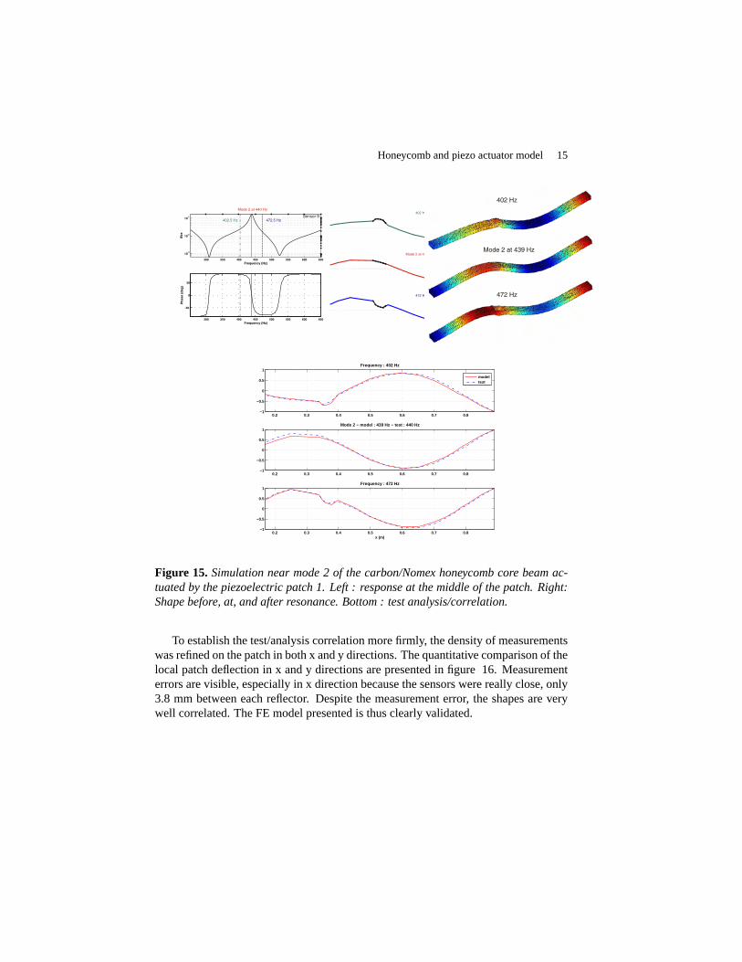
Figure 15. Simulation near mode 2 of the carbon/Nomex honeycomb core beam ac-tuated by the piezoelectric patch 1. Left : response at the middle of the patch. Right:Shape before, at, and after resonance. Bottom : test analysis/correlation.
To establish the test/analysis correlation more firmly, the density of measurementswas refined on the patch in both x and y directions. The quantitative comparison of thelocal patch deflection in x and y directions are presented in figure 16. Measurementerrors are visible, especially in x direction because the sensors were really close, only3.8 mm between each reflector. Despite the measurement error, the shapes are verywell correlated. The FE model presented is thus clearly validated.

16 RCMA. Volume 00 – n˚0/2009
400 Hz
xz
y
Mode 2 at 436.2 Hz 458.7 Hz
400 Hz
xz
y
Mode 2 at 439.2 Hz 458 Hz
Figure 16. Test (top) and simulation (bottom): before resonance at 400Hz, at reso-nance, and after resonance at 458Hz.
For vibration applications, the response is a linear combination of the modal con-tributions and a quasi-static effect, often called residual flexibility (Craig, 1987). Theblister shape is the deformation generated by the application of a static voltage on thepatch. The test detailed in this section illustrated the fact that the residual flexibilitycannot be neglected outside resonances. This effect has an obvious limiting effecton the ability to control noise radiated by the panel since control of the modes willgenerate a local noise source even on the skin opposite to the patch.
5. Strategies for integrating piezos into FE models
Having validated a FE model, this section focuses on the practical implementationof the modeling strategy. The model considered in previous sections implies signifi-cant adaptations. As shown in figure 17/a, the mesh is adapted in the vicinity of thepatch and two composite properties are considered. One for the standard honeycombskin (shown in blue in the figure) and one for the patch which includes multiple layersfor the skin plus two layers for the patch, as shown in figure 8.
This approach is fine for a small beam model and if only few configurations ofpatch locations are considered. Indeed, the adaptation of the mesh under the patcheswould be quite time consuming for a large panel where multiple patch configurationswould need to be tested. Furthermore, the use of viscoelastic materials in the glue,considered by many in the literature, implies the use of a multi-layered model withthe glue represented as a volume element.
The idea tested in this work is thus to use separate elements to model the skin andthe piezoelectric patch, with linear constraints used to account for the offset betweenthe two. The shear stiffness of the glue layer (G/h) is deemed sufficiently high tosuppose perfect bonding and thus omit glue modeling.

Honeycomb and piezo actuator model 17
An automated procedure was introduced to mesh the patch. Based on a givenrectangular shape, skin elements strictly under the patch are projected to the patchmid-surface. The boundary between the projected elements and the edge of the refer-ence rectangle is then meshed automatically. The resulting model is shown in figure17/c. This approach is deemed more acceptable than an adaptation of the honeycombmesh because it only affects a small part of the model and would be adapted for thereuse of modes of the nominal panel.
As an intermediate validation, a model with two layers (skin and piezo) but anadapted underlying mesh is also considered and shown in 17/b.
Figure 17. Piezoelectric patch model strategy: a/ adapted meshing and integratedpatch, b/ adapted meshing and 2 layers (patch and face sheet), c/ non-adapted mesh-ing and 2 layers.
To compare these models, electric transfers are shown in figure 18 and piezo tolaser transfers in figure 19. For a cross transfer from voltage input on piezo 2 tovoltage output on piezo 1, the responses are almost perfectly superposed. For theimpedanceQP iezo2
VP iezo2however, there is a significant offset of about 30% on the static
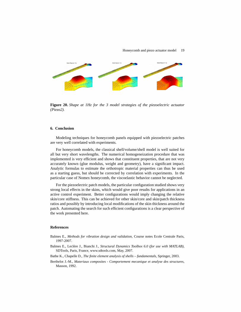
response. This error can reasonably be attributed to the lack of adaptation of themesh on the patch edges. This is illustrated in figure 20 which shows the quasi-static shaped generated by the actuation (since the structure is free floating, one showsthe deformation at 1 Hz which avoids problems linked to rigid body modes). The

18 RCMA. Volume 00 – n˚0/2009
deformations clearly show that the blister shape under the patch cannot be perfectlyreproduced due to the lack of mesh adaptation.
The proposed strategy using multiple-elements through the thickness is thus lim-ited by the ability to reproduce local effects under the patch. The local nature of thiseffect is clearly considered a design flaw of the considered configuration. With betterdesigns, the patch would induce bending with much greater wave length and the meshadaptation would probably be not as necessary.
Figure 18. Electric transfers for the 3 model strategies. Input is piezo 2 used asvoltage driven actuator.Left piezo 1 used as voltage sensor.Right Charge generatedon piezo 2.
Figure 19. Piezo to laser sensor transfer .
Honeycomb and piezo actuator model 19
Figure 20. Shape at 1Hz for the 3 model strategies of the piezoelectric actuator(Piezo2).
6. Conclusion
Modeling techniques for honeycomb panels equipped with piezoelectric patchesare very well correlated with experiments.
For honeycomb models, the classical shell/volume/shell model is well suited forall but very short wavelengths. The numerical homogeneization procedure that wasimplemented is very efficient and shows that constituent properties, that are not veryaccurately known (glue modulus, weight and geometry), have a significant impact.Analytic formulas to estimate the orthotropic material properties can thus be usedas a starting guess, but should be corrected by correlation with experiments. In theparticular case of Nomex honeycomb, the viscoelastic behavior cannot be neglected.
For the piezoelectric patch models, the particular configuration studied shows verystrong local effects in the skins, which would give poor results for applications in anactive control experiment. Better configurations would imply changing the relativeskin/core stiffness. This can be achieved for other skin/core and skin/patch thicknessratios and possibly by introducing local modifications of the skin thickness around thepatch. Automating the search for such efficient configurations is a clear perspective ofthe work presented here.
References
Balmes E.,Methods for vibration design and validation, Course notes Ecole Centrale Paris,1997-2007.
Balmes E., Leclère J., Bianchi J.,Structural Dynamics Toolbox 6.0 (for use with MATLAB),SDTools, Paris, France, www.sdtools.com, May, 2007.
Bathe K., Chapelle D.,The finite element analysis of shells – fundamentals, Springer, 2003.
Berthelot J.-M.,Materiaux composites - Comportement mecanique et analyse des structures,Masson, 1992.

20 RCMA. Volume 00 – n˚0/2009
Bihan D. L., Lepage A., Florens C., Roudolff F., “ Contrôle Actif de panneaux composites”,Technical Report RT 1/08836 DDSS, Avril 2005.
Clouteau D., Arnst M., Al-Hussaini T., G. D., “ Free field vibrations due to dynamic loadingon a tunnel embedded in a stratified medium”,Journal of Sound and Vibration, vol. 238,p. 173-199, 2005.
Craig R. J., “ A Review of Time-Domain and Frequency Domain Component Mode SynthesisMethods”,Int. J. Anal. and Exp. Modal Analysis, vol. 2, n˚ 2, p. 59-72, 1987.
Florens C., Balmes E., Clero F., Corus M., “ Accounting for glue and temperature effects inNomex based honeycomb models”,ISMA, September, 2006.
Gibson L. J., Ashby M. F.,Cellular Solids Structure and Properties, Second Edition, CambridgeUniversity Press, 1997.
Grédiac M., “ A finite element study of the transverse shear in honeycomb cores”,InternationalJournal of Solids and Structures, vol. 30(13), p. 1777-1788, 1993.
Hohe J., Becker W., “ A refined analysis of the effective elasticity tensor for general cellularsandwich cores”,International Journal of Solids and Structures, vol. 38, p. 3689-3717,2001.
Jones R. M.,Mechanics of Composite Materials, Hemisphere Publishing Corp., 1975.
Noor A., Burton W., “ Assessment of continuum models for sandwich panel honeycomb cores”,Computer methods in applied mechanics and engineering, vol. 145, p. 341-360, 1997.
Piefort V., Finite Element Modelling of Piezoelectric Active Structures, PhD thesis, ActiveStructures Laboratory Department of Mechanical Engineering and Robotics, Université Li-bre de Bruxelles, Belgium., 2001.
Sternchüss, A. and Balmes, E. and Jean, P. and Lombard, JP., “ Reduction of Multistage diskmodels : application to an industrial rotor”,012502, 2008. Paper Number GT2008-012502.

ANNEXE POUR LE SERVICE FABRICATIONA FOURNIR PAR LES AUTEURS AVEC UN EXEMPLAIRE PAPIERDE LEUR ARTICLE ET LE COPYRIGHT SIGNE PAR COURRIER
LE FICHIER PDF CORRESPONDANT SERA ENVOYE PAR E-MAIL
1. ARTICLE POUR LA REVUE:
RCMA. Volume 00 – n˚0/2009
2. AUTEURS :
Etienne Balmes* — Corine Florens**
3. TITRE DE L’ ARTICLE :
Validation of a vibration and electric model of honeycomb panels equipedwith piezoelectric patch actuators
4. TITRE ABRÉGÉ POUR LE HAUT DE PAGE MOINS DE40 SIGNES:
Honeycomb and piezo actuator model
5. DATE DE CETTE VERSION:
17th April 2009
6. COORDONNÉES DES AUTEURS:
– adresse postale :* Arts et Metiers ParisTech (LMSP)151 Bld de l’Hopital, 75013 Paris
** ONERA DADS, 92322 Chatillon CedexEcole Centrale Paris, MSSMat, 92295 Chatenay Malabry
– téléphone : 01 44 24 63 71
– télécopie : 00 00 00 00 00
– e-mail : [email protected]
7. LOGICIEL UTILISÉ POUR LA PRÉPARATION DE CET ARTICLE:
LATEX, avec le fichier de stylearticle-hermes.cls,version 1.23 du 17/11/2005.
8. FORMULAIRE DE COPYRIGHT:
Retourner le formulaire de copyright signé par les auteurs, téléchargé sur :http://www.revuesonline.com
SERVICE ÉDITORIAL – HERMES-LAVOISIER
14 rue de Provigny, F-94236 Cachan cedexTél. : 01-47-40-67-67
E-mail : [email protected] web : http://www.revuesonline.com