Embed Size (px)
Citation preview
June 23, 2004 NASA Goddard Space Flight Center
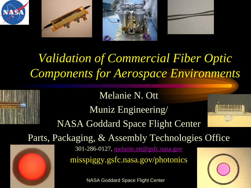
Validation of Commercial Fiber Optic Components for Aerospace Environments
Melanie N. OttMuniz Engineering/
NASA Goddard Space Flight CenterParts, Packaging, & Assembly Technologies Office
301-286-0127, [email protected]
misspiggy.gsfc.nasa.gov/photonics
March 9, 2005 NASA Goddard Space Flight Center
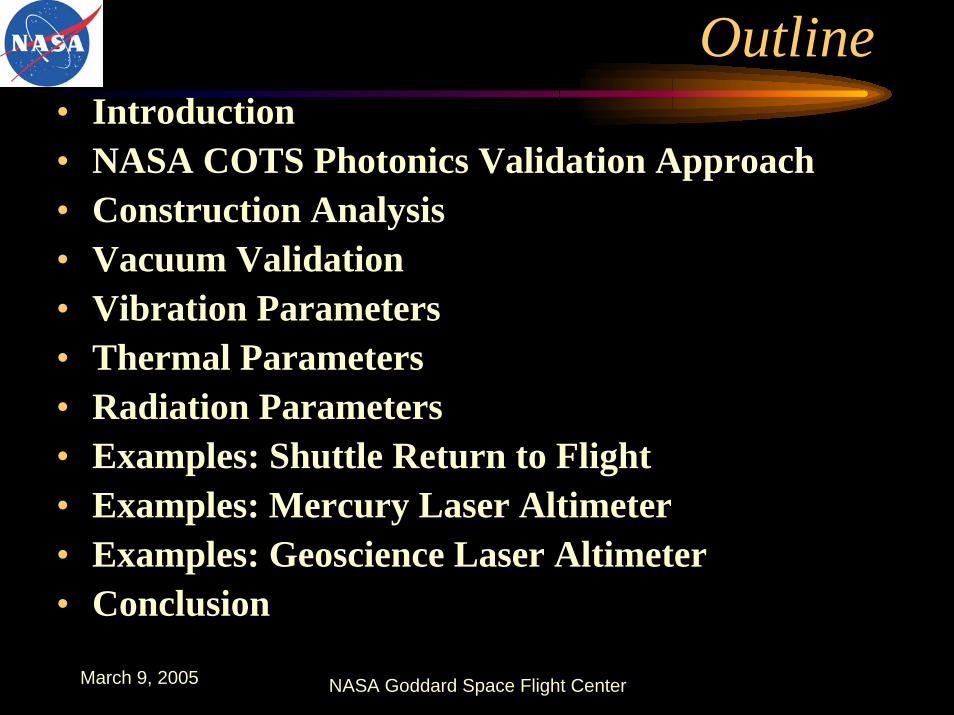
Outline• Introduction• NASA COTS Photonics Validation Approach• Construction Analysis• Vacuum Validation• Vibration Parameters• Thermal Parameters• Radiation Parameters• Examples: Shuttle Return to Flight• Examples: Mercury Laser Altimeter• Examples: Geoscience Laser Altimeter• Conclusion
March 9, 2005 NASA Goddard Space Flight Center
IntroductionChanges in Our GSFC Environment
Short term projects, low budgetsInstruments like GLAS, MLA, VCL
Changes to the Mil-Spec system, NASA relied heavily.Telecommunications products available, state-of-the-art.Vendors and parts rapidly changing.Most photonics now COTS.Qualification not only impossible but far too expensive.Characterization of COTS for risk mitigation.Quality by similarity where possible.
March 9, 2005 NASA Goddard Space Flight Center
COTS Technology Assurance Approach For Space Flight
System Requirements: Define critical component parameters and the quantity by how each can deviate from optimal performance as a result and during testing.
Environmental RequirementsContamination and materials requirements.Box level random vibration, double for componentThermal environment, 10 C higher at extremesRadiation, worst case conditions.
Failure Modes Study• Conditions and Parameters
Test Methods• Tailored to capturing the largest amount of failure modes while testing for space
environment.
Test Plan• Contains necessary testing for mission while monitoring for failure modes.
March 9, 2005 NASA Goddard Space Flight Center
Qualification PlanDefine critical parameters that must be stable during testing.Define acceptable changes in performance parameters as a final result of testing and during testing (dynamic and permanent). Define part or system to be tested. How many samples can you afford to test (considering time, equipment, materials)
Materials Analysis,Outgas testing for anything unknown, take configuration into account.Packaging!
Vibration Survival and “Shock” Test Use component levels as defined by system requirementsDefine parameters to monitor during testing
Thermal Cycling/Aging TestDefine which parameters will indicate which failure modeMonitor those parameters during testing.
Radiation TestingAccelerated dose rate, extrapolation model use if possible, worst conditions
Addition test based on specific mission requirements?
March 9, 2005 NASA Goddard Space Flight Center
Construction/Materials Analysis
Destructive Physical AnalysisIdentify packaging issues
Gases Analysis, hermetic?Materials identification,
Packaging: wirebonds, die attach materialsIdentify non metallic materials for vacuum exposure
Potential contamination issues.
Construction Analysis is crucial!Long Term Reliability Will it survive harsh environments?
March 9, 2005 NASA Goddard Space Flight Center
Environmental Parameters
• Vacuum requirements• Vibration requirements• Thermal requirements• Radiation requirements
March 9, 2005 NASA Goddard Space Flight Center
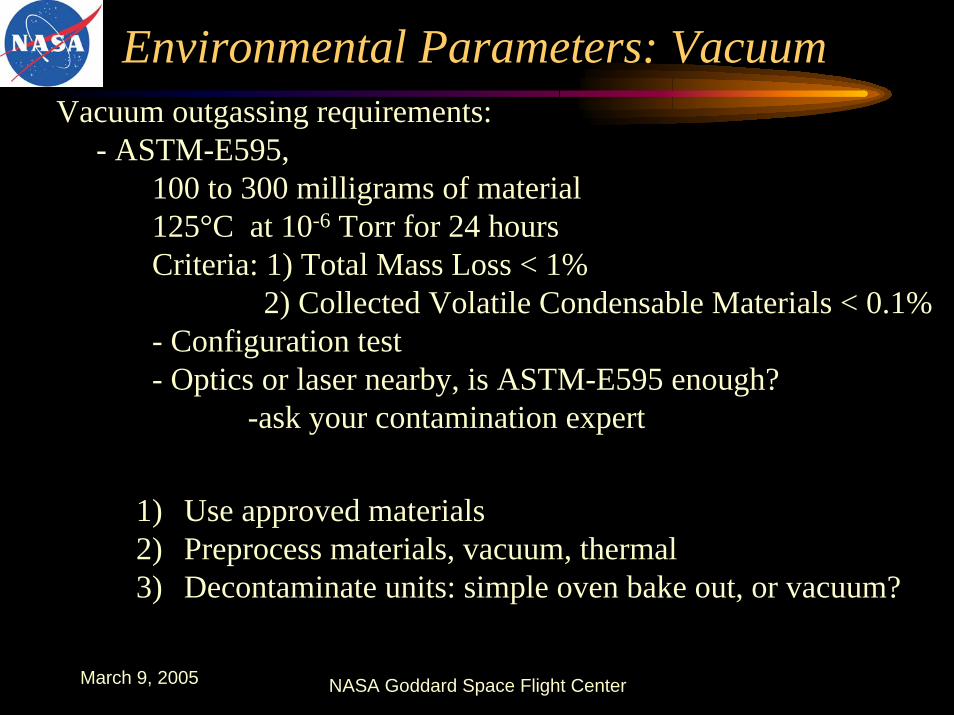
Environmental Parameters: VacuumVacuum outgassing requirements:
- ASTM-E595, 100 to 300 milligrams of material125°C at 10-6 Torr for 24 hoursCriteria: 1) Total Mass Loss < 1%
2) Collected Volatile Condensable Materials < 0.1% - Configuration test- Optics or laser nearby, is ASTM-E595 enough?
-ask your contamination expert
1) Use approved materials2) Preprocess materials, vacuum, thermal 3) Decontaminate units: simple oven bake out, or vacuum?
March 9, 2005 NASA Goddard Space Flight Center
Environmental Parameters: Vibration
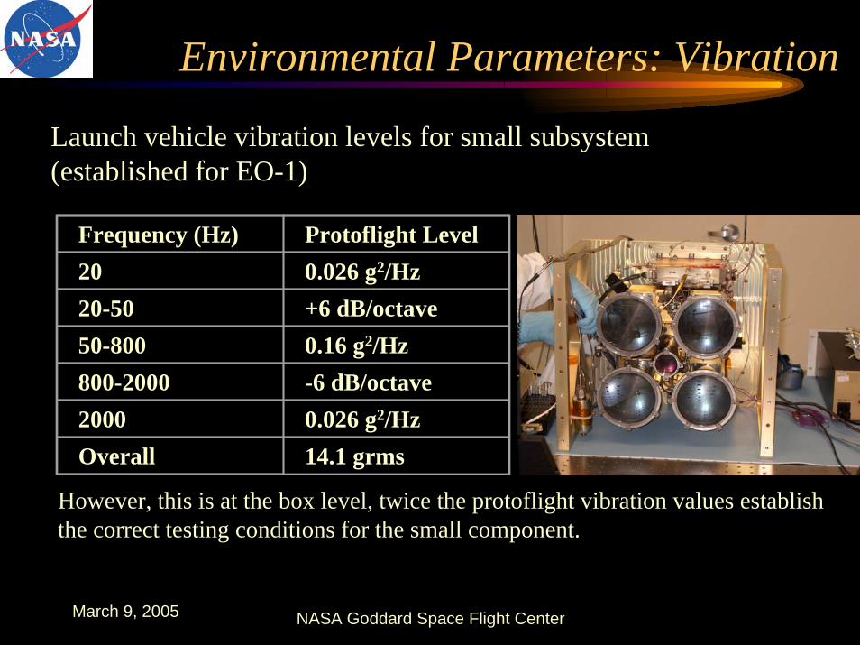
Launch vehicle vibration levels for small subsystem (established for EO-1)
Frequency (Hz) Protoflight Level20 0.026 g2/Hz20-50 +6 dB/octave50-800 0.16 g2/Hz800-2000 -6 dB/octave2000 0.026 g2/HzOverall 14.1 grms
However, this is at the box level, twice the protoflight vibration values establish the correct testing conditions for the small component.

March 9, 2005 NASA Goddard Space Flight Center
Environmental Parameters: Vibration
Launch vehicle vibration levels for small component(based on box level established for EO-1) on the “high” side.
Frequency (Hz) Protoflight Level20 0.052 g2/Hz20-50 +6 dB/octave50-800 0.32 g2/Hz800-2000 -6 dB/octave2000 0.052 g2/HzOverall 20.0 grms
3 minutes per axis, tested in x, y and z
March 9, 2005 NASA Goddard Space Flight Center
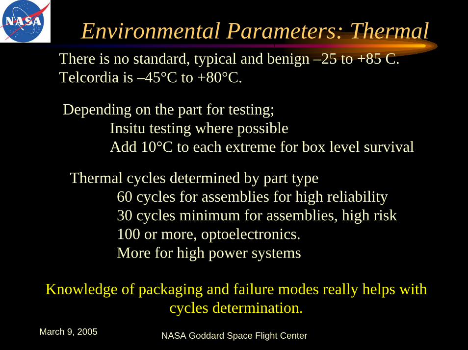
Environmental Parameters: ThermalThere is no standard, typical and benign –25 to +85 C.Telcordia is –45°C to +80°C.
Depending on the part for testing;Insitu testing where possible Add 10°C to each extreme for box level survival
Thermal cycles determined by part type60 cycles for assemblies for high reliability 30 cycles minimum for assemblies, high risk100 or more, optoelectronics. More for high power systems
Knowledge of packaging and failure modes really helps with cycles determination.
March 9, 2005 NASA Goddard Space Flight Center
Environmental Parameters: Radiation
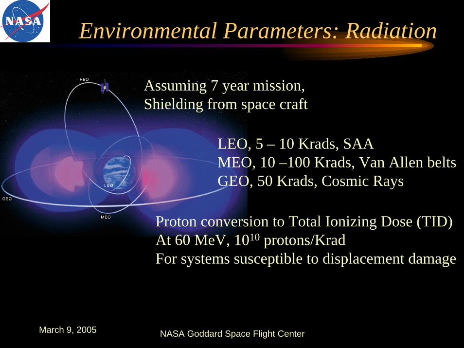
LEO, 5 – 10 Krads, SAAMEO, 10 –100 Krads, Van Allen beltsGEO, 50 Krads, Cosmic Rays
Assuming 7 year mission,Shielding from space craft
Proton conversion to Total Ionizing Dose (TID)At 60 MeV, 1010 protons/KradFor systems susceptible to displacement damage
March 9, 2005 NASA Goddard Space Flight Center
Environmental Parameters: RadiationTypical space flight background radiation total dose30 Krads – 100 Krads over 5 to 10 year mission.
Dose rates for fiber components:• GLAS, 100 Krads, 5 yr, .04 rads/min• MLA, 30 Krads, 8 yr, .011 rads/min (five year ave)• EO-1, 15Krads, 10 yr, .04 rads/min
Any other environmental parameters that need to be considered?For example, radiation exposure at very cold temp, or prolonged
extreme temperature exposure based on mission demands.
March 9, 2005 NASA Goddard Space Flight Center
Shuttle Return to Flight: Construction Analysis
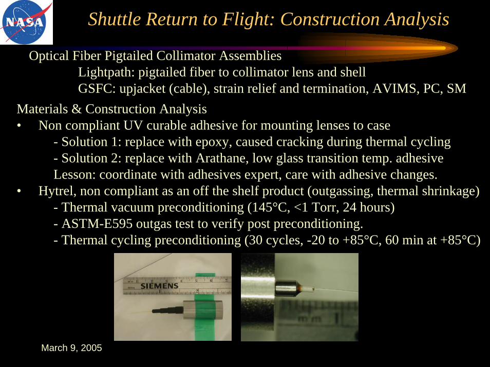
Optical Fiber Pigtailed Collimator AssembliesLightpath: pigtailed fiber to collimator lens and shellGSFC: upjacket (cable), strain relief and termination, AVIMS, PC, SM
Materials & Construction Analysis• Non compliant UV curable adhesive for mounting lenses to case
- Solution 1: replace with epoxy, caused cracking during thermal cycling- Solution 2: replace with Arathane, low glass transition temp. adhesiveLesson: coordinate with adhesives expert, care with adhesive changes.
• Hytrel, non compliant as an off the shelf product (outgassing, thermal shrinkage)- Thermal vacuum preconditioning (145°C, <1 Torr, 24 hours)- ASTM-E595 outgas test to verify post preconditioning.- Thermal cycling preconditioning (30 cycles, -20 to +85°C, 60 min at +85°C)

March 9, 2005 NASA Goddard Space Flight Center
Shuttle Return to Flight Laser Diode Assemblies
Fitel: laser diode pigtailsGSFC: Upjacket (cable), strain relief, termination, AVIMS APC SMFitel uses silicone boot, non-compliant!Too late in fabrication process, schedule considerations to preprocess.
Cable: Thermal preconditioning, 30 cyclesHytrel boots: Vacuum preconditioning, 24 hoursKynar heat shrink tubing, epoxy: approved for space use.
Post manufacturing decontamination of entire
assembly requiredLaser diode rated for 85°C
processing performed at 70°C
March 9, 2005 NASA Goddard Space Flight Center
Mercury Laser Altimeter (MLA): Construction Analysis
Optical Fiber AssembliesDiamond AVIMS connector / W.L. Gore FlexlitePolymicro Technologies FIA 200/220Performance: <.04 dB loss
Preconditioning of non metallic materials and failure modes knowledge of construction
Hytrel boots: Thermal vacuum precondition: 140°C, 24 hrs, 1 TorrFlexlite cable: Thermal preconditioning, 8 cycles, -20 to +60°C, 60 min at 60°C Epotek 353ND: approved for space.
Post processing decontamination of assemblies @ 50°C (To bake out but not to age)Cure schedule on outgassing database is very high temp.Best to use close to usage temp cure, with a post cure bake out

March 9, 2005 NASA Goddard Space Flight Center
MLA Assembly Environmental Validation
Requirements/Testing: Performance < .4 dB for all, 850 nmVibration 14.1 grms, 3 min/axis
Because box level @ 10 grmsThermal: -30°C to +50 °C, 90 cycles, last 42 monitored
25 minute soak, 2 °C/min ramp rates.Radiation: two dose rate model, -20°C,
11.2 and 22.7 rads/min to 30 Krads(Actual dose rate .011 rads/min)
SPIE Vol. 5104
March 9, 2005 NASA Goddard Space Flight Center
MLA Assembly Environmental Validation
0 0.5 1 1.5 2 2.5 3 3.5
x 104
0
0.1
0.2
0.3
0.4
0.5
0.6
0.7
0.8
0.9High Dos e Ra te Ra d-Induc e d Atte nua tion for 200 (re d) & 300 (blue ) Fle xlite Ca ble
Rad
iatio
n In
duce
d A
ttenu
atio
n (d
B)
Tota l Dos e (ra ds )
300 mic ron
0.818 dB
0.892 dB 200 m ic ron
0 0.5 1 1.5 2 2.5 3 3.5
x 104
0
0.2
0.4
0.6
0.8
1
1.2
1.4Low Dos e Ra te Rad-Induc e d Attenua tion for 200 (red) & 300 (blue ) Fle xlite Ca ble
Rad
iatio
n In
duce
d A
ttenu
atio
n (d
B)
Tota l Dos e (ra ds )
300 m ic ron
200 m ic ron
1.024 dB
0.917 dB
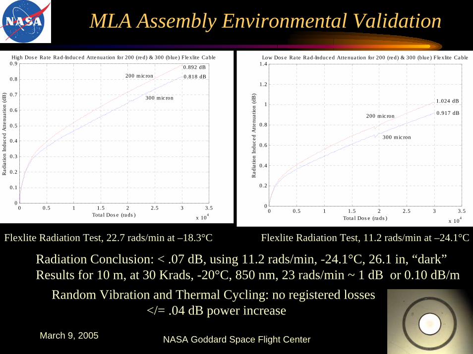
Flexlite Radiation Test, 22.7 rads/min at –18.3°C Flexlite Radiation Test, 11.2 rads/min at –24.1°C
Radiation Conclusion: < .07 dB, using 11.2 rads/min, -24.1°C, 26.1 in, “dark”Results for 10 m, at 30 Krads, -20°C, 850 nm, 23 rads/min ~ 1 dB or 0.10 dB/m
Random Vibration and Thermal Cycling: no registered losses</= .04 dB power increase
March 9, 2005 NASA Goddard Space Flight Center
Geoscience Laser Altimeter (GLAS):Fiber, Assemblies, Diodes
• Fiber– Variety of candidates, radiation analysis based on
previously published data, quality by similarity.– Database funded by NEPP,
• IEEE NSREC Data Workshop 2002(misspiggy.gsfc.nasa.gov/photonics)
– Electron testing for scintillation effects. • Cable Assemblies (AVIMS, Flexlite)
– Quality by similarity, tested by Lockheed-Martin.• Laser Diodes
– Never performed a construction analysis and devices failed in space flight.
March 9, 2005 NASA Goddard Space Flight Center
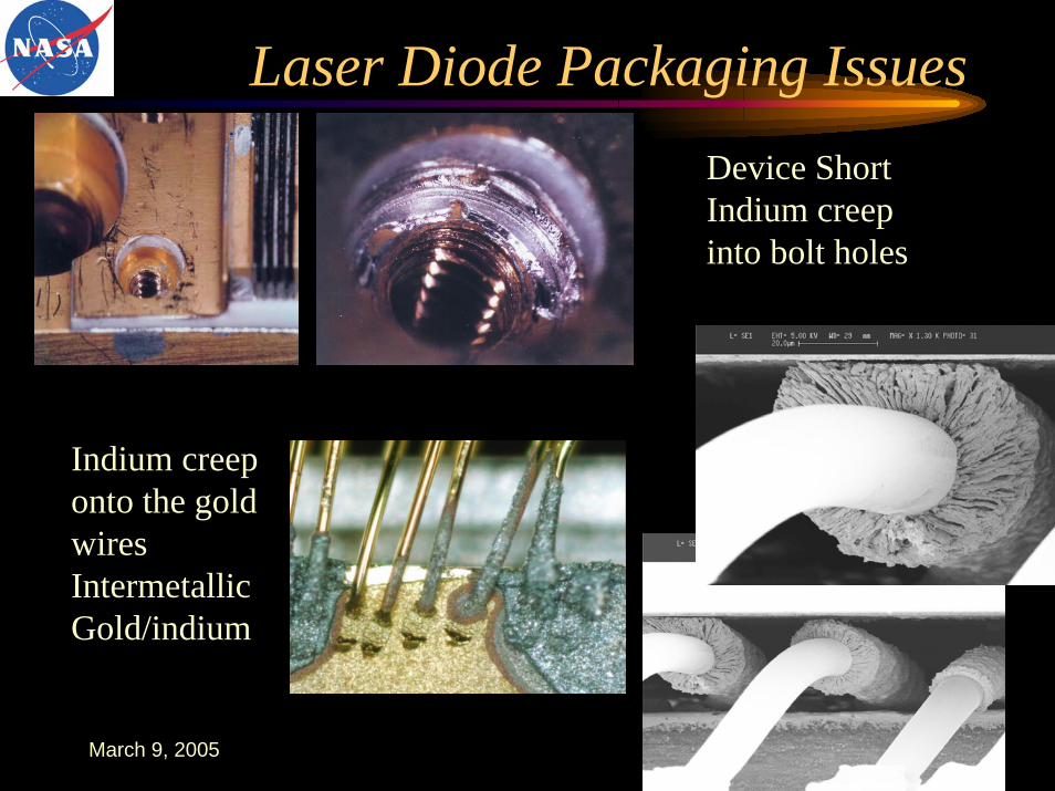
Laser Diode Packaging IssuesDevice ShortIndium creep into bolt holes
Indium creep onto the gold wiresIntermetallicGold/indium
March 9, 2005 NASA Goddard Space Flight Center
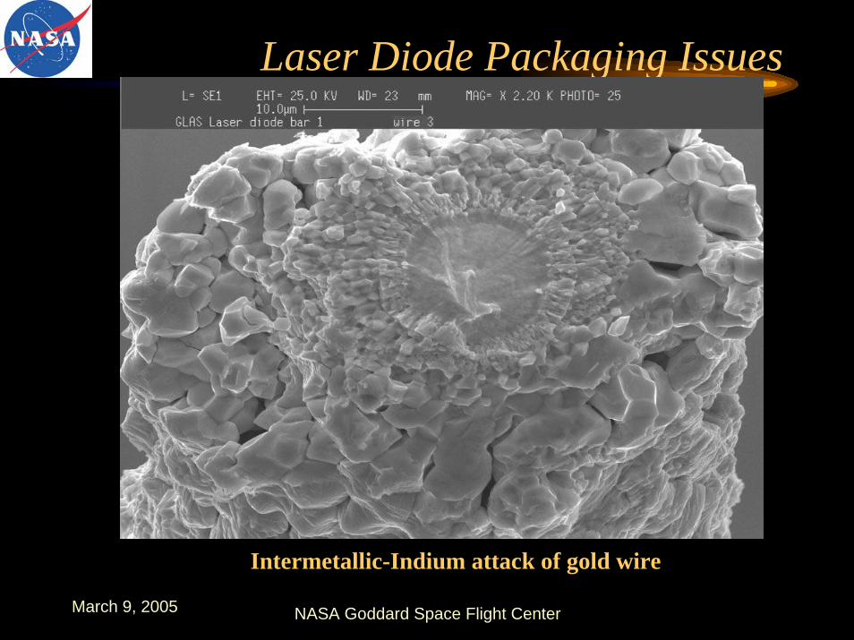
Laser Diode Packaging Issues
Intermetallic-Indium attack of gold wire
March 9, 2005 NASA Goddard Space Flight Center
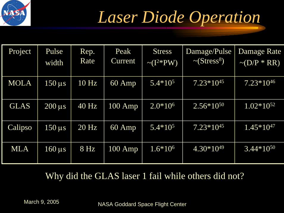
Laser Diode Operation
Project Pulsewidth
Rep. Rate
Peak Current
Stress~(I2*PW)
Damage/Pulse~(Stress8)
Damage Rate~(D/P * RR)
MOLA 150 µs 10 Hz 60 Amp 5.4*105 7.23*1045 7.23*1046
GLAS 200 µs 40 Hz 100 Amp 2.0*106 2.56*1050 1.02*1052
Calipso 150 µs 20 Hz 60 Amp 5.4*105 7.23*1045 1.45*1047
MLA 160 µs 8 Hz 100 Amp 1.6*106 4.30*1049 3.44*1050
Why did the GLAS laser 1 fail while others did not?
March 9, 2005 NASA Goddard Space Flight Center
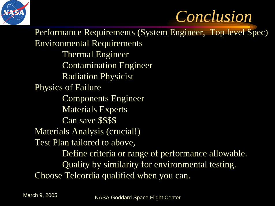
ConclusionPerformance Requirements (System Engineer, Top level Spec)Environmental Requirements
Thermal EngineerContamination EngineerRadiation Physicist
Physics of FailureComponents EngineerMaterials ExpertsCan save $$$$
Materials Analysis (crucial!)Test Plan tailored to above,
Define criteria or range of performance allowable.Quality by similarity for environmental testing.
Choose Telcordia qualified when you can.
March 9, 2005 NASA Goddard Space Flight Center
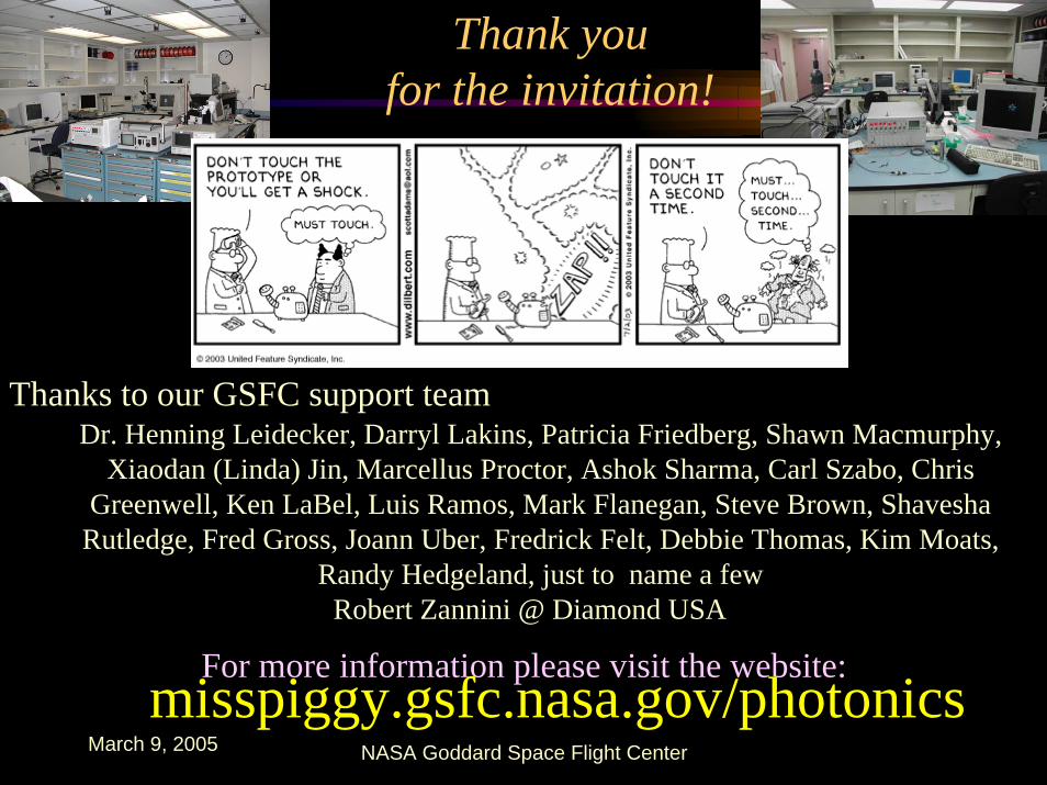
Thank you for the invitation!
For more information please visit the website:misspiggy.gsfc.nasa.gov/photonics
Dr. Henning Leidecker, Darryl Lakins, Patricia Friedberg, Shawn Macmurphy, Xiaodan (Linda) Jin, Marcellus Proctor, Ashok Sharma, Carl Szabo, Chris
Greenwell, Ken LaBel, Luis Ramos, Mark Flanegan, Steve Brown, Shavesha Rutledge, Fred Gross, Joann Uber, Fredrick Felt, Debbie Thomas, Kim Moats,
Randy Hedgeland, just to name a few
Thanks to our GSFC support team
Robert Zannini @ Diamond USA
March 9, 2005 NASA Goddard Space Flight Center
Back up slides start here

March 9, 2005 NASA Goddard Space Flight Center
Laser Diode Packaging IssuesGLAS, MOLA, MLA, Calipso use high power laser diode bar arrays for pumping of solid state lasers.
Indium creep (shorting, intermetallics)
Cracking of semiconductor from wedgebonds
Diffusion layer pinholes
Dendrite growth of tin/lead solder
Contamination related failure (hermetic packaging)
Workmanship Issues (application of indium solder)

March 9, 2005 NASA Goddard Space Flight Center
Laser Diode Packaging Issues
Copper
BeO
Indium solder
Wedgebond related cracking
Pictures from Dr. Henning Leidecker’s presentation “Failure Analysis of GLAS Laser Diode Arrays,” Community Forum on Laser Diode Arrays in Space-Based Applications, 2004
Indium solder bond broke
Crack resulted in low res. Path to wires
Workmanship:application of Indium solder
March 9, 2005 NASA Goddard Space Flight Center
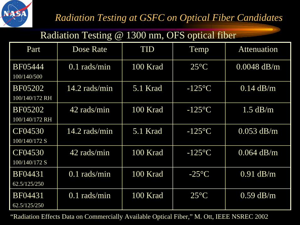
Radiation Testing at GSFC on Optical Fiber Candidates
Radiation Testing @ 1300 nm, OFS optical fiberPart Dose Rate TID Temp Attenuation
BF05444100/140/500
0.1 rads/min 100 Krad 25°C 0.0048 dB/m
BF05202100/140/172 RH
14.2 rads/min 5.1 Krad -125°C 0.14 dB/m
BF05202100/140/172 RH
42 rads/min 100 Krad -125°C 1.5 dB/m
CF04530100/140/172 S
14.2 rads/min 5.1 Krad -125°C 0.053 dB/m
CF04530100/140/172 S
42 rads/min 100 Krad -125°C 0.064 dB/m
BF0443162.5/125/250
0.1 rads/min 100 Krad -25°C 0.91 dB/m
BF0443162.5/125/250
0.1 rads/min 100 Krad 25°C 0.59 dB/m
“Radiation Effects Data on Commercially Available Optical Fiber,” M. Ott, IEEE NSREC 2002
March 9, 2005 NASA Goddard Space Flight Center
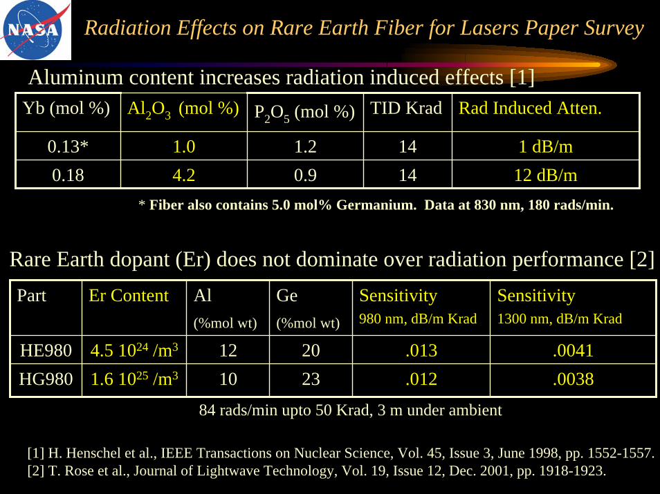
Radiation Effects on Rare Earth Fiber for Lasers Paper Survey
Aluminum content increases radiation induced effects [1]Yb (mol %) Al2O3 (mol %) P2O5 (mol %) TID Krad Rad Induced Atten.
0.13* 1.0 1.2 14 1 dB/m0.18 4.2 0.9 14 12 dB/m
* Fiber also contains 5.0 mol% Germanium. Data at 830 nm, 180 rads/min.
Rare Earth dopant (Er) does not dominate over radiation performance [2]Part Er Content Al
(%mol wt)
Ge (%mol wt)
Sensitivity980 nm, dB/m Krad
Sensitivity1300 nm, dB/m Krad
HE980 4.5 1024 /m3 12 20 .013 .0041HG980 1.6 1025 /m3 10 23 .012 .0038
84 rads/min upto 50 Krad, 3 m under ambient
[1] H. Henschel et al., IEEE Transactions on Nuclear Science, Vol. 45, Issue 3, June 1998, pp. 1552-1557.[2] T. Rose et al., Journal of Lightwave Technology, Vol. 19, Issue 12, Dec. 2001, pp. 1918-1923.
March 9, 2005 NASA Goddard Space Flight Center
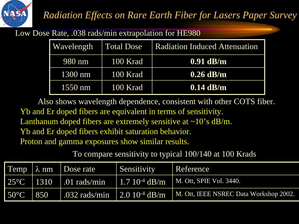
Radiation Effects on Rare Earth Fiber for Lasers Paper Survey
Low Dose Rate, .038 rads/min extrapolation for HE980Wavelength Total Dose Radiation Induced Attenuation
980 nm 100 Krad 0.91 dB/m1300 nm 100 Krad 0.26 dB/m1550 nm 100 Krad 0.14 dB/m
Also shows wavelength dependence, consistent with other COTS fiber.Yb and Er doped fibers are equivalent in terms of sensitivity.Lanthanum doped fibers are extremely sensitive at ~10’s dB/m.Yb and Er doped fibers exhibit saturation behavior.Proton and gamma exposures show similar results.
To compare sensitivity to typical 100/140 at 100 Krads
Temp λ nm Dose rate Sensitivity Reference25°C 1310 .01 rads/min 1.7 10-4 dB/m M. Ott, SPIE Vol. 3440.
50°C 850 .032 rads/min 2.0 10-4 dB/m M. Ott, IEEE NSREC Data Workshop 2002.