Embed Size (px)
Citation preview
© all rights reserved Page 1 of 85 January 2011
Joint Office of Gas Transporters T/PR/ME/2 Part 3 _____________________________________________________________________
WORK PROCEDURE FOR VALIDATION OF EQUIPMENT ASSOCIATED WITH MEASUREMENT SYSTEMS FOR THE CALCULATION OF MASS, VOLUME AND ENERGY FLOW RATE OF GAS PART 3: FLOW WEIGHTED AVERAGE CALORIFIC VALUE OFFTAKES _____________________________________________________________________
© all rights reserved Page 2 of 85 January 2011
CONTENTS FORWARD 3
BRIEF HISTORY 3 DISCLAIMER 3
MANDATORY AND NON-MANDATORY REQUIREMENTS 4 INTRODUCTION 4
1. SCOPE 4 2. REFERENCES 5
3. DEFINITIONS 5 4. GENERAL PREPARATIONS AND PRECAUTIONS 5
5. STATUTORY COMPLIANCE DURING MAINTENANCE 6 6. TESTING 8
7. COMPLETING THE VALIDATION FORM 9 8. GENERAL REQUIREMENTS 9
9. HEALTH SAFETY AND ENVIRONMENT 11 10. REINSTATEMENT 12
11. SUMMARY OF TEST PROCEDURES 13 12. INDEX OF TEST PROCEDURES: FOR FLOW METERING VALIDATION AT
OFFTAKES 14 TEST PROCEDURES 14

© all rights reserved Page 3 of 85 January 2011
FORWARD This Work Procedure was approved by the Uniform Network Code (UNC) Offtake Committee on 07/09/09 for use by managers, engineers and supervisors throughout the National Transmission System and the Distribution Networks. This is an Offtake Subsidiary Document as defined in Section N1.2 of the Offtake Arrangements Document (OAD) of the UNC. These documents are revised, when necessary, by the Offtake Committee in accordance with OAD N8.5. Users shall ensure that they are in possession of the latest edition by referring to the Joint Office of Gas Transporters website. Compliance with this document does not confer immunity from prosecution for breach of statutory or other legal obligations.
BRIEF HISTORY
First published as T/PR/ME2 Part 3. March 2001 EPSG/T02/658
Editorial update to reflect demerger November 2000.
June 2001
Revised and re-issued. April 2004
Editorial update to reflect Safety Case version 3 taking into account issues as detailed in the comments below. Additionally, compliance with mandatory terms along with the removal of no specific normative phrases.
July 2004
Editorial update to comply with GRM. October 2004 EPSG/A04/10129
Re-branded, updated and approved by the Offtake Committee. Minor changes approved by the Offtake Committee
November 2009 June 2010
Minor change approved by the Offtake Committee
January 2011
DISCLAIMER This Offtake Subsidiary Document is provided for use by the Transporters and such of their contractors as are obliged by the terms and conditions of their contracts to comply with this document. Where this document is used by any other party it is the responsibility of that party to ensure that this document is correctly applied.
© all rights reserved Page 4 of 85 January 2011
MANDATORY AND NON-MANDATORY REQUIREMENTS In this document:
shall: indicates a mandatory requirement. should: indicates best practice and is the preferred option. If an alternative
method is used then a suitable and sufficient risk assessment shall be completed to show that the alternative method delivers the same, or better, level of protection.
INTRODUCTION This Work Procedure has been produced to ensure that validation of gas flow metering systems is performed consistently by the Transporters.
1. SCOPE This Work Procedure shall be used to demonstrate that instrumentation and equipment associated with measurement systems for the calculation of mass, volume or energy flow rate of gas are functioning correctly, thus ensuring that the complete metering system continues to perform within the uncertainty requirements as defined in the Transporter’s Gas Requirements Manual (GRM) or equivalent. This Work Procedure forms a suite to cover the validation of differing types of metering systems installed at connections to the Transporters’ above 7 bar networks: Part 1: General Requirements Part 2: Generic Procedures Part 3: Flow Weighted Average Calorific Value Offtakes Parts 4 and 5 relating to power stations and Very Large Daily Metered Consumers (VLDMCs) are not Offtake Subsidiary Documents and are therefore governed by the relevant Transporters outside UNC governance. This Work Procedure is to be used by the Transporters for the following types of connection: a) NTS to LDZ transfer b) Inter-LDZ transfer c) Entry points to LDZ (ie storage, landfill sites or onshore fields). This Work Procedure may also be used to validate third party measurement systems for the calculation of mass, volume and energy flow rate of gas connected to the national balancing point (NBP) in the absence of any other procedures. Part 3 applies to Offtakes where the measurements for volume and energy are associated with the calculation of flow weighted average calorific value and
© all rights reserved Page 5 of 85 January 2011
applies to Ofgem directed and non-directed Offtakes. It typically applies to the following: a) NTS to LDZ transfer b) Inter-LDZ transfer c) Entry points to LDZ (ie storage, landfill sites or onshore fields).
2. REFERENCES This document makes reference to documents listed in Appendix A of T/PR/ME/2 Part 1. Unless otherwise specified, the relevant editions of the documents apply, including addenda and revisions.
3. DEFINITIONS For the purpose of this Work Procedure the definitions given in T/PR/ME/2 Part 1 apply.
4. GENERAL PREPARATIONS AND PRECAUTIONS The following list is intended as a guide to the preparations/precautions that are required prior to the commencement of validation/calibration work. It is not a substitute for the local safe working practices or controls. A number of the procedures include additional advice on the preparations and precautions that are appropriate to the activities defined within the procedure: a) Ensure the appropriate permitry to work has been granted. b) Check the calibration records of the equipment to be checked/calibrated.
Assess the calibration stability and investigate any operating problems that occurred since its last check/calibration.
c) Ensure that the values of all entered data required by the flow computer are consistent with the latest revision of the approved master configuration.
d) Ensure that all calibration/test equipment conforms to the necessary specification requirement for T/PM/ME/2 use, is fully charged where appropriate, is ready for use and calibrated by a suitably accredited test facility. An in-date calibration certificate shall be available during these activities.
e) Where main process lines are broken/opened, ensure that a gas detector is available and suitable protective clothing is worn. Leak detection fluid should be available to determine the integrity of the re-connected system.
f) Ensure that suitable power supplies are available as necessary. g) Observe work permit conditions.
© all rights reserved Page 6 of 85 January 2011
5. STATUTORY COMPLIANCE DURING MAINTENANCE During maintenance, the measured flow will not necessarily be the actual flow through the Offtake, and an estimate of the volume flowing through the Offtake shall be made by the affected system operators (for the purposes of system balancing and the calculation of flow weighted average calorific value (CV)). In order to comply with regulatory requirements during meter maintenance, the following shall be performed: a) Communication with the Affected System Operators
i) The affected system operators shall be advised of the intention to undertake work four (4) weeks before commencement.
ii) If the maintenance period is estimated to exceed eight (8) hours, or if the CV sample point is by-passed, then the affected system operators shall be informed.
b) Procedures before and after Maintenance
i) The affected system operators shall be informed that maintenance is to be carried out at an Offtake, and be given details of the effects on any values or processes.
ii) Prior to maintenance, the affected system operator should ensure that gas is made to flow between 20% and 100% of maximum meter tube design capacity are possible in order to establish a footprint to compare the pre and post work profile of the Offtake.
iii) The following shall be recorded by the affected system operator on the booking on/off form, and the site operatives shall also record this in the Meter Logbook:
• Date;
• Time;
• Calorific Value (CV);
• Specific Gravity (SG) (also referred to as Relative Density (RD));
• Inlet, outlet and meter pressure;
• Flow control valve (FCV)/position/pressure set-point (PSP), where applicable;
• Standby differential pressure (mbar), where present;
• Standard volume flow rate;
• Volume flow integrator reading (Omni flow computer);
• Volume flow integrator reading (telemetry).

© all rights reserved Page 7 of 85 January 2011
NB All meter values should be obtained from the Omni flow computer, apart from the FCV/PSP, which should be obtained from the Offtake telemetry unit.
iv) To minimise the potential for errors occurring when estimating hourly flows, the control valves should be fixed in Direct Valve Control (DVC) and the signal from the affected system operator isolated. If this is not possible, the Offtake shall be shut down and the appropriate loops isolated.
v) At the end of the maintenance, the affected system operator shall attempt to replicate conditions at the start of the maintenance.
vi) Check and agree with the affected system operator that the start and finish volume flow rates are comparable, considering the maintenance activities undertaken and the similarity of the flow conditions. For a Pressure Control Offtake, the affected system operator shall use a comparable demand Day to assess whether the flows are as expected. If the values are not as expected, the site operative shall re-check that all instrumentation has been correctly reinstated. Maintenance should only be completed when reasons for any unexpected discrepancy have been determined and corrected.
vii) Providing that the checks are acceptable, the valve(s) shall be reinstated and the controlling signal(s) from the affected system operator re-established.
c) Flow Rate Modification
If the volume flow calculated by the flow computer is being affected by the maintenance, the following shall be undertaken: i) Omni Flow Computer Maintenance Mode
The maintenance mode in the flow computer shall be enabled as follows: NB This will result in a fixed LGT injection flow rate. • Press front panel keys PROG INPUT ENTER;
• Enter "1.0" (without the inverted commas) to put the Omni into Maintenance mode;
• Press PROG to return to DISPLAY mode;
• Enable the DANINT maintenance mode (second set, F12).
• At the end of the maintenance period, repeat the above, but enter "-1.0" (again without the inverted commas) into the Omni to disable the maintenance mode. "Maintenance" is written into the alarm data file when it is activated. At the end of the maintenance period, ensure that Danint and the Danalyzer are returned to their normal operating state as detailed within T/PR/GQ/3.
© all rights reserved Page 8 of 85 January 2011
ii) Local Gas Treatment (LGT) The LGT system injects odorant in proportion to the flow rate calculated within the Omni flow computer. Any modifications that influence the injection rate of the LGT system shall be undertaken in accordance with T/PM/MAINT/8, as defined within procedure CP6c ‘DAC Check / Manual over-ride (LGT)’. At the end of the maintenance period, ensure that the Omni and LGT systems are returned to their normal operating conditions by confirming that (with gas flowing) the LGT injection flow rate corresponds to the instantaneous flow measured by the flow computer.
d) Records i) Meter Maintenance
Details of work undertaken on meter systems shall be recorded in the Meter Logbook/HPMIS Ofgem log as appropriate.
ii) Validation Results On completion of any of the check/calibration procedures, the Offtake Validation Record sheet within the High Pressure Metering Information System, or alternative record, shall be completed with:
• Date;
• Check procedure number;
• Stream number;
• Status of the check, ie AF/AL, AF, AL or AF2 (see 7, below);
• Any relevant comment;
• Who made the entry. iii) Meter Faults
Meter faults shall be recorded within the Meter Logbook/HPMIS Ofgem log. All faults found with the metering equipment shall be reported to the affected system operator who shall record the details within its database logging system. Details shall also be reported to the responsible engineering manager without delay. NB The Danalyzer Record sheets shall be completed if the CV,
RD, or gas composition data are affected.
6. TESTING The applicable procedures detailed in Section 11 shall be undertaken at the stated frequency.
© all rights reserved Page 9 of 85 January 2011
All results shall be recorded on the appropriate test Results form and signed by the tester and, where appropriate, by a witness. Subsequent authorisation will also be required by a nominated approver. All records shall be retained for future inspection and audit.
7. COMPLETING THE VALIDATION FORM The maintenance forms within High Pressure Metering Information System (HPMIS), or alternative, shall be completed. The following guidance is provided for Offtakes where access to HPMIS has not been provided or is unavailable. Under these circumstances, a spreadsheet is to be used to record the validation results. Where access to HPMIS is normally available at the Offtake, but the system is discovered to be unavailable at the time of validation, the site operative shall contact the responsible engineering manager to report the fault and agree to default to using a spreadsheet to record results. Where a spreadsheet is used as the alternative to HPMIS, the following notes are applicable, apart from the reference to the use of two sheets for twin stream sites where a single sheet shall be used if provision is made and agreed. As much detail as possible has been included in the relevant check procedure to assist completion of the validation form, however, the following general advice is given:
• A yellow box requires an entry - data cannot be entered into any other cell.
• In the Status section, the following entries are automatically made:
“AF/AL” As Found/As Left: check acceptable without recalibration
“AF” As Found: check unacceptable without recalibration
“AL” As Left: check acceptable after recalibration
“AF2” As Found no. 2: check unacceptable after recalibration
• Any recalibration shall be described in the Comments section of the form containing the data after any action was taken. The final results shall be recorded on the second form on the same sheet.
• The completed spreadsheet shall be returned to the responsible engineering manager without delay. Completion of CP17 and/or provision of an orifice plate calibration certificate shall not delay this process.
• Results for two stream Offtakes shall be recorded on separate spreadsheets.
8. GENERAL REQUIREMENTS All Offtakes shall be validated no less frequently than once every twelve (12) months.
© all rights reserved Page 10 of 85 January 2011
The validation of an Offtake is considered complete when all the relevant tests for that Offtake meet the acceptance criteria defined within each of the test procedures. When validating an Offtake, if any test fails to meet the acceptance criteria defined within the test procedures, the affected equipment shall, where reasonably practicable be repaired/replaced and revalidated within fourteen (14) Business Days. The validation of an Offtake shall be completed within one (1) month of commencement. When the validation of a meter is completed, the site operative shall complete a Validation Completion Certificate within HPMIS or alternative. There are many ways the process of performing the validation can be made more efficient. This section outlines a few suggestions: a) Whilst undertaking the maintenance procedure, it is necessary to edit the live
Omni configuration.. This introduces the potential for errors to be introduced to the system once the maintenance is completed. The integrity of the system shall therefore be protected by making a backup of the Omni configuration. This Omni configuration file shall be saved to the supervisory system prior to making changes to the live configuration. Once the maintenance procedure is completed the configuration shall then be transferred back to the Omni along with only the necessary updates to ensure the integrity of the Omni configuration post-validation is retained. The configuration file shall be saved using a naming convention that clearly identifies the Offtake name, and the date, eg:
SSSYMMDD.OMI format for file name Where:- SSS = Offtake abbreviation, eg STF = St Fergus Y = year as letter 2008 = N, 2009 = O, 2010 = P, 2011 = Q MM = Month (eg March = 03) DD = Day (eg 4th = 04).
b) Several tests can be performed in a more efficient manner if they are carried out during the same day and in a particular order:
• CP1, CP2, CP3 - similar data values are required to be fixed in the flow computer for each of these checks;
• CP4, CP10, CP11 - as the dead-weight tester is arranged to provide pressures which correspond to nominal current outputs (0%, 25%, 50%, 75%, 100%), the analogue to digital converter (ADC) of the flow computer can be checked at the same time;
© all rights reserved Page 11 of 85 January 2011
• CP6a, CP6b - same process taking readings from different parts of the system.
NB Care must be taken to preserve the “As Found” operating condition of the equipment prior to intervention, in order that an appropriate and valid assessment can be made to quantify any meter mis-measurement. For instance, for an orifice plate system any offset determined in CP11 Hook up Procedure should be established prior to disturbance of the system prior to calibration activities.
9. HEALTH, SAFETY AND ENVIRONMENT It shall be noted that when undertaking work based upon this Work Procedure, activities shall be assessed in order to mitigate the risk of harm or injury, in accordance with any current HSE or company guidance. Risk assessments shall be undertaken to ensure that safe working procedures are established and applied. For example the following risks should be considered as a minimum: a) Working on high pressure systems; b) Lifting operations, including lifting orifice plates and turbine meters in and out
of pipes and during transit to and from the Offtake; c) Configuration of LGT injection flow rates; d) Isolation of electrical/instrumentation systems; e) Exposure to contaminated instrumentation systems; f) Working within potentially hazardous areas; g) Forcing the output of the Omni computer can result in changes to the values
displayed by the affected system operator. The operation of Offtakes shall be managed to avoid valves operating in response to forced calibration signals;
h) Debris may be ejected from high pressure pipes during venting operations; i) Waste oil and grease drained or cleaned from instrumentation systems shall
be contained and disposed of in a controlled manner; j) Turbine and/or ultrasonic meters removed for calibration and/or repair shall
be purged prior to transportation; k) Following the completion of the validation work, gas should be made to flow
through the metering system and comparison made with previous installation behaviour to determine suitable equipment reinstatement;
l) All Offtake work (including any remote maintenance) shall be coordinated with the affected system operator to address the risk of inadvertent operations;
m) Potential damage to plant caused by rapid changes in the flow rate and/or pressure shall be avoided.
© all rights reserved Page 12 of 85 January 2011
10. REINSTATEMENT Whilst applying the validation procedures, a number of modifications may have to be made to the metering system in order to force and record values. Such modifications involve both disconnecting physical instruments (or wires) and software edits. Upon completion of the validation, the system shall be reinstated to correctly record energy and volume flows. Checks shall be undertaken to ensure all circuits are properly reinstated and any forced values are removed. All default failure modes shall be reinstated. All software edits shall reflect the “As Left” status of the meter system and a copy of the Omni configuration shall be suitably named and backed up onto the supervisory system.
© all rights reserved Page 13 of 85 January 2011
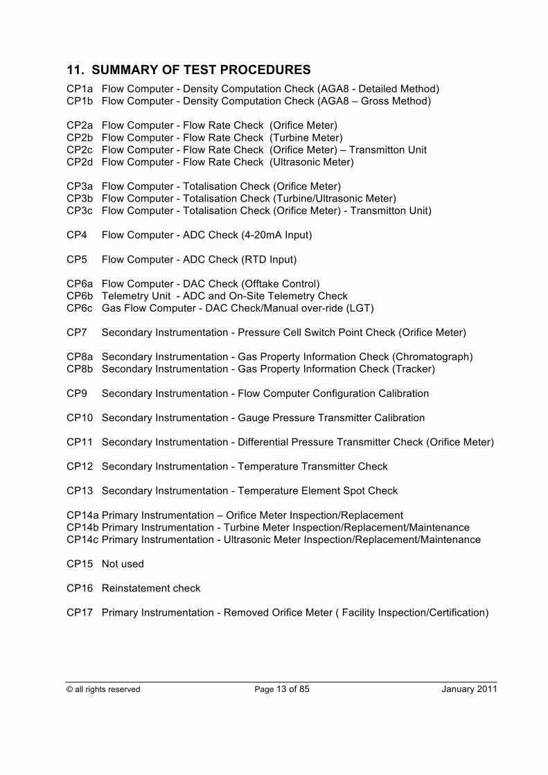
11. SUMMARY OF TEST PROCEDURES CP1a Flow Computer - Density Computation Check (AGA8 - Detailed Method) CP1b Flow Computer - Density Computation Check (AGA8 – Gross Method) CP2a Flow Computer - Flow Rate Check (Orifice Meter) CP2b Flow Computer - Flow Rate Check (Turbine Meter) CP2c Flow Computer - Flow Rate Check (Orifice Meter) – Transmitton Unit CP2d Flow Computer - Flow Rate Check (Ultrasonic Meter) CP3a Flow Computer - Totalisation Check (Orifice Meter) CP3b Flow Computer - Totalisation Check (Turbine/Ultrasonic Meter) CP3c Flow Computer - Totalisation Check (Orifice Meter) - Transmitton Unit) CP4 Flow Computer - ADC Check (4-20mA Input) CP5 Flow Computer - ADC Check (RTD Input) CP6a Flow Computer - DAC Check (Offtake Control) CP6b Telemetry Unit - ADC and On-Site Telemetry Check CP6c Gas Flow Computer - DAC Check/Manual over-ride (LGT) CP7 Secondary Instrumentation - Pressure Cell Switch Point Check (Orifice Meter) CP8a Secondary Instrumentation - Gas Property Information Check (Chromatograph) CP8b Secondary Instrumentation - Gas Property Information Check (Tracker) CP9 Secondary Instrumentation - Flow Computer Configuration Calibration CP10 Secondary Instrumentation - Gauge Pressure Transmitter Calibration CP11 Secondary Instrumentation - Differential Pressure Transmitter Check (Orifice Meter) CP12 Secondary Instrumentation - Temperature Transmitter Check CP13 Secondary Instrumentation - Temperature Element Spot Check CP14a Primary Instrumentation – Orifice Meter Inspection/Replacement CP14b Primary Instrumentation - Turbine Meter Inspection/Replacement/Maintenance CP14c Primary Instrumentation - Ultrasonic Meter Inspection/Replacement/Maintenance CP15 Not used CP16 Reinstatement check CP17 Primary Instrumentation - Removed Orifice Meter ( Facility Inspection/Certification)
© all rights reserved Page 14 of 85 January 2011
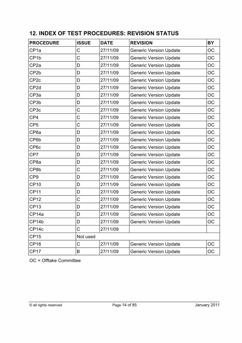
12. INDEX OF TEST PROCEDURES: REVISION STATUS PROCEDURE ISSUE DATE REVISION BY CP1a C 27/11/09 Generic Version Update OC CP1b C 27/11/09 Generic Version Update OC CP2a D 27/11/09 Generic Version Update OC CP2b D 27/11/09 Generic Version Update OC CP2c D 27/11/09 Generic Version Update OC CP2d D 27/11/09 Generic Version Update OC CP3a D 27/11/09 Generic Version Update OC CP3b D 27/11/09 Generic Version Update OC CP3c C 27/11/09 Generic Version Update OC CP4 C 27/11/09 Generic Version Update OC CP5 C 27/11/09 Generic Version Update OC CP6a D 27/11/09 Generic Version Update OC CP6b D 27/11/09 Generic Version Update OC CP6c D 27/11/09 Generic Version Update OC CP7 D 27/11/09 Generic Version Update OC CP8a D 27/11/09 Generic Version Update OC CP8b C 27/11/09 Generic Version Update OC CP9 D 27/11/09 Generic Version Update OC CP10 D 27/11/09 Generic Version Update OC CP11 D 27/11/09 Generic Version Update OC CP12 C 27/11/09 Generic Version Update OC CP13 D 27/11/09 Generic Version Update OC CP14a D 27/11/09 Generic Version Update OC CP14b D 27/11/09 Generic Version Update OC CP14c C 27/11/09 CP15 Not used CP16 C 27/11/09 Generic Version Update OC CP17 B 27/11/09 Generic Version Update OC
OC = Offtake Committee
© all rights reserved Page 15 of 85 January 2011
TEST PROCEDURES In relation to all procedures, this document provides guidance for site operatives regarding key stroke sequences on the Omni Flow Computer. These sequences predominantly relate to Omni firmware v27.71.xx. These sequences may be different for other firmware types. It is the responsibility of the site operative to apply the alternative as appropriate
© all rights reserved Page 16 of 85 January 2011
FLOW COMPUTER DENSITY COMPUTATION CHECK (AGA8 – DETAILED METHOD)
Proc No CP1a
ISSUE C
This check shall be carried out to verify that the flow computer is calculating upstream density correctly to the relevant density computation routine (AGA8 - Detailed Method), by comparing the displayed value with an expected value of calculated upstream density.
FREQUENCY OF TEST: Twelve (12) months
ACCEPT/REJECT CRITERIA:
± 0.002% of reading
FALLBACK PROCEDURE: Check all the data values used. Ensure the gas chromatograph derived composition has not changed. Repeat the check. If still out of specification, log the fault with the responsible engineering manager without delay.
PREPARATIONS/PRECAUTIONS a) The affected system operator shall be advised, prior to undertaking this
procedure, in order that it may manage the operation of the Offtake and account for errors introduced to the declared on-site telemetry flow rate.
b) It shall be noted that, when setting default values, the calculated flow within the Omni will be affected, resulting in a change in analogue outputs. The following shall be considered: i) The on-site telemetry will display a corresponding instantaneous
volumetric flow rate, which could result in unexpected valve movements if either the Offtake is not set in DVC and/or the signal to the valve has not been isolated.
ii) The LGT system shall be configured, as defined within CP6c, to prevent the injection of odorant in proportion to the simulated flow.
TEST PROCEDURE
a) Stop communication to the supervisory system [ONLINE>OMNI CONFIG>CONFIG SERIAL I/O> SERIAL I/O#3: change MODBUS ID from 1 to 22].
b) Where appropriate, depending upon meter system type and using the override facility, enter suitable data into the flow computer for the following:
© all rights reserved Page 17 of 85 January 2011
c) Temperature [ONLINE> TEMP/PRESS SETUP> TEMPERATURE #meter no: change OVERRIDE CODE from 3 to 1, set i) OVERRIDE VALUE to a suitable value]; ii) Pressure [ONLINE> TEMP/PRESS SETUP> PRESSURE #meter no:
change OVERRIDE CODE from 3 to 1, set OVERRIDE VALUE to a suitable value];
iii) Differential Pressure [ONLINE> DIFF. PRESSURE SETUP>DIFF. PRESSURE #meter no: change OVERRIDE CODE from 3 to 1, set OVERRIDE VALUE to a suitable value].
d) Enter the following data onto the calibration form: i) Temperature value entered; ii) Upstream Temperature [Front panel key press METER 1 TEMP, then
DISPLAY and scroll down]; iii) Pressure value entered; iv) Gas Composition [ONLINE> FLUID DATA & ANALYSIS]; v) Flow Computer calculated Compressibility [Front panel key press TEMP
FACTOR DISPLAY] and Density [Front panel key press I,O (stream 1) or P (stream 2), then DISPLAY];
vi) Calculate the Compressibility and Density using “AGA8 (1994) - Detailed Method”, using the upstream conditions and enter the values onto the Results form.
REINSTATEMENT a) Reinstate in accordance with CP16; b) After completion, enter YES in the "Reinstate Equipment?" box.
© all rights reserved Page 18 of 85 January 2011
FLOW COMPUTER DENSITY COMPUTATION CHECK (AGA8 – GROSS METHOD)
Proc No CP1b
ISSUE C
This check shall be carried out to verify that the flow computer is calculating upstream density correctly to the relevant density computation routine (AGA8 - Gross Method) by comparing the displayed value with an expected value of calculated upstream density.
FREQUENCY OF TEST: Twelve (12) months
ACCEPT/REJECT CRITERIA:
± 0.02% of reading
FALLBACK PROCEDURE: Check all the data values used. Ensure the gas tracker values (RD, CV) have not changed. Repeat the check. If still out of specification, log the fault with the responsible engineering manager without delay.
PREPARATIONS/PRECAUTIONS a) The affected system operator shall be advised prior to undertaking this
procedure, in order that it may manage the operation of the Offtake and account for errors introduced to the declared flow rate.
b) It shall be noted that, when setting default values, the calculated flow within the Omni will be affected, resulting in a change in analogue outputs. The following shall be considered: i) The on-site telemetry will display a corresponding instantaneous
volumetric flow rate, which could result in unexpected valve movements, if either the Offtake is not set in DVC and/or the signal to the valve has not been isolated.
ii) The LGT system shall be configured, as defined within CP6c, to prevent the injection of odorant in proportion to the simulated flow.
TEST PROCEDURE
a) Stop communication to the supervisory system [ONLINE>OMNI CONFIG>CONFIG SERIAL I/O> SERIAL I/O#3: change MODBUS ID from 1 to 22].
b) Where appropriate, depending upon meter system type and using the override facility, enter suitable data into the flow computer for the following:
© all rights reserved Page 19 of 85 January 2011
i) Temperature [ONLINE> TEMP/PRESS SETUP> TEMPERATURE #meter no: change OVERRIDE CODE from 3 to 1, set OVERRIDE VALUE to a suitable value];
ii) Pressure [ONLINE> TEMP/PRESS SETUP> PRESSURE #meter no: change OVERRIDE CODE from 3 to 1, set OVERRIDE VALUE to a suitable value];
iii) Differential Pressure [ONLINE> DIFF. PRESSURE SETUP>DIFF. PRESSURE #meter no: change OVERRIDE CODE from 3 to 1, set OVERRIDE VALUE to a suitable value].
c) Enter the following data onto the calibration form: i) Temperature value entered; ii) Upstream Temperature [Front panel key press METER 1 TEMP, then
DISPLAY and scroll down]. iii) Pressure value entered; iv) Relative Density and Calorific Value [Front panel key press I,O (stream 1)
or P (stream 2), then DISPLAY]; v) Mole percent Carbon Dioxide [ONLINE> FLUID DATA & ANALYSIS]; vi) Flow Computer calculated Compressibility [Front panel key press TEMP
FACTOR DISPLAY] and Density [Front panel key press I,O (stream 1) or P (stream 2), then DISPLAY].
d) Calculate the Compressibility and Density using “AGA8 (1994) - Gross Method”, using the upstream conditions and enter the values onto the Results form.
REINSTATEMENT
a) Reinstate in accordance with CP16; b) After completion, enter YES in the "Reinstate Equipment?" box.
© all rights reserved Page 20 of 85 January 2011
FLOW COMPUTER FLOW RATE CHECK (ORIFICE METER)
Proc No CP2a
ISSUE D
This check shall be carried out to verify that the computer is calculating stream flow rates correctly by "setting" flow conditions and comparing displayed flow rates with expected values.
FREQUENCY OF TEST: Twelve (12) months
ACCEPT/REJECT CRITERIA:
± 0.001% of reading
FALLBACK PROCEDURE: Check all the data values used and repeat the check. If still out of specification, log the fault with the responsible engineering manager without delay.
PREPARATIONS/PRECAUTIONS a) The affected system operator shall be advised prior to undertaking this
procedure, in order that it may manage the operation of the Offtake and account for errors introduced to the declared the on-site telemetry flow rate.
b) It shall be noted that, when setting default values, the calculated flow within the Omni will be affected, resulting in a change in analogue outputs. The following shall be considered: i) The on-site telemetry will display a corresponding instantaneous
volumetric flow rate, which could result in unexpected valve movements, if either the Offtake is not set in DVC and/or the signal to the valve has not been isolated.
ii) The LGT system shall be configured, as defined within CP6c, to prevent the injection of odorant in proportion to the simulated flow.
TEST PROCEDURE a) Stop communication to the supervisory system [ONLINE>OMNI CONFIG>
CONFIG SERIAL I/O> SERIAL I/O#3: change MODBUS ID from 1 to 22]. b) Using the override facility, enter suitable data into the flow computer for the
following: i) Temperature [ONLINE> TEMP/PRESS SETUP> TEMPERATURE
#meter no: change OVERRIDE CODE from 3 to 1, set OVERRIDE VALUE to a suitable value];
© all rights reserved Page 21 of 85 January 2011
ii) Pressure [ONLINE> TEMP/PRESS SETUP> PRESSURE #meter no: change OVERRIDE CODE from 3 to 1, set OVERRIDE VALUE to a suitable value];
iii) Differential Pressure [ONLINE> DIFF. PRESSURE SETUP>DIFF. PRESSURE #meter no: change OVERRIDE CODE from 3 to 1, set OVERRIDE VALUE to a suitable value].
NB This test shall be repeated three (3) times, using varying data for Pressure and Differential Pressure, to cover the flow range of the stream.
c) Enter the following data onto the calibration form Input Data section:
i) Pipe Diameter at Calibration Temperature [ONLINE> METER RUN SETUP];
ii) Pipe Diameter Calibration Temperature [ONLINE> METER RUN SETUP];
iii) Pipe Expansion Factor [ONLINE> METER RUN SETUP]; iv) Orifice Diameter at Calibration Temperature [ONLINE> METER RUN
SETUP]; v) Orifice Plate Calibration Temperature [ONLINE> METER RUN SETUP]; vi) Orifice Plate Expansion Factor [ONLINE> METER RUN SETUP]; vii) (Dynamic) Viscosity [ONLINE> FLUID DATA & ANALYSIS]; viii) Isentropic Exponent [ONLINE> FLUID DATA & ANALYSIS]; ix) Relative Density [Front panel key press I,O (stream 1) or P (stream 2),
then DISPLAY] (see note below); x) Calorific Value [Front panel key press I,O (stream 1) or P (stream 2), then
DISPLAY]; xi) Density of Air at Metric Standard Conditions [ONLINE>FACTOR
SETUP+SYS CONSTANTS]; xii) Atmospheric Pressure [ONLINE>FACTOR SETUP+SYS CONSTANTS]; xiii) Entered Temperature value.
REINSTATEMENT a) Reinstate in accordance with CP16; b) After completion, enter YES in the "Reinstate Equipment?" box.
© all rights reserved Page 22 of 85 January 2011
FLOW COMPUTER FLOW RATE CHECK (TURBINE METER)
Proc No CP2b
ISSUE D
This check shall be carried out to verify that the computer is calculating stream flow rates correctly by “setting” flow conditions and comparing displayed flow rates with expected values.
FREQUENCY OF TEST: Twelve (12) months
ACCEPT/REJECT CRITERIA:
± 0.001% of reading
FALLBACK PROCEDURE: Check all the data values used and repeat the check. If still out of specification, log the fault with the responsible engineering manager without delay.
PREPARATIONS/PRECAUTIONS a) The affected system operator shall be advised prior to undertaking this
procedure, in order that it may manage the operation of the site and account for errors introduced to the declared the on-site telemetry flow rate.
b) It shall be noted that, when setting default values, (the calculated flow within the Omni will be affected, resulting in a change in analogue outputs. The following shall be considered: i) The on-site telemetry will display a corresponding instantaneous
volumetric flow rate, which could result in unexpected valve movements, if either the Offtake is not set in DVC and/or the signal to the valve has not been isolated.
ii) The LGT system shall be configured, as defined within CP6c, to prevent the injection of odorant in proportion to the simulated flow.
HOOK UP PROCEDURE Substitute the turbine meter input with a calibrated pulse generator with a switching voltage greater than 3.6V but less than 12V. The terminal connections are dependent upon the Offtake configuration and are defined within the Offtake specific instrument loop drawings.
© all rights reserved Page 23 of 85 January 2011
TEST PROCEDURE a) Stop communication to the supervisory system [ONLINE>OMNI CONFIG>
CONFIG SERIAL I/O> SERIAL I/O#3: change MODBUS ID from 1 to 22]. b) Using the override facility, enter suitable data into the flow computer for the
following: i) Temperature [ONLINE> TEMP/PRESS SETUP> TEMPERATURE
#meter no: change OVERRIDE CODE from 3 to 1, set OVERRIDE VALUE to a suitable value];
ii) Pressure [ONLINE> TEMP/PRESS SETUP> PRESSURE #meter no: change OVERRIDE CODE from 3 to 1, set OVERRIDE VALUE to a suitable value] and set using the pulse generator:
iii) Pulse frequency. NB This test shall be repeated three (3) times, using varying data for pressure
and pulse frequency, to cover the flow range of the metering stream.
c) Enter the following data onto the calibration form Input Data section: i) Relative Density [Front panel key press I,O (stream 1) or P (stream 2),
then DISPLAY]; ii) Density of Air at Metric Standard Conditions [ONLINE>FACTOR SET-
UP]; iii) Calorific Value [Front panel key press I,O (stream 1) or P (stream 2), then
DISPLAY]; iv) Entered Temperature value.
REINSTATEMENT a) Reinstate in accordance with CP16; b) After completion, enter YES in the "Reinstate Equipment?" box.
© all rights reserved Page 24 of 85 January 2011
FLOW COMPUTER FLOW RATE CHECK (ORIFICE METER) TRANSMITTON UNIT
Proc No CP2c
ISSUE D
This check shall be carried out to verify the accuracy of the Transmitton unit flow rate calculation and the overall flow metering accuracy by using test equipment to input required values into the Transmitton unit and comparing the flow rate displayed with the calculated value. NB The secondary instrumentation checks should be performed prior to this check.
FREQUENCY OF TEST: Twelve (12) months
ACCEPT/REJECT CRITERIA:
± 0.8% of reading
FALLBACK PROCEDURE: Check all the data values used and repeat the check. If still out of specification:
a) Check the Transmitton displayed input readings are appropriate for the actual inputs;
b) Check the ADC precision reference voltage levels across the following test points on the MT48 card:
TP12 -TP14 0.1221V TP13 -TP14 4.8840V
and if incorrect, adjust the relevant pots on the MT48 card;
c) Then check the Transmitton values: E1 BD24 2.44% E1 BD25 97.68%
and if incorrect, adjust the relevant pots on the MT4(A) card for a MKI or MKII, or MT70 card for a MKIII Transmitton unit.
If the test is still out of tolerance, log the fault with the responsible engineering manager without delay.
© all rights reserved Page 25 of 85 January 2011
PREPARATIONS/PRECAUTIONS a) The affected system operator shall be advised prior to undertaking this
procedure, in order that it may manage the operation of the Offtake and account for errors introduced to the declared the on-site telemetry flow rate.
b) It shall be noted that, when injecting values, the calculated flow within the Transmitton will be affected, resulting in a change in analogue outputs. The following shall be considered: i) The on-site telemetry will display a corresponding instantaneous
volumetric flow rate, which could result in unexpected valve movements, if either the Offtake is not set in DVC and/or the signal to the valve has not been isolated.
ii) The LGT system shall be configured, in accordance with CP6c, to prevent the injection of odorant in proportion to the simulated flow.
HOOK UP PROCEDURE a) Pressure and differential pressure transmitters
i) Isolate the pressure and differential pressure transmitters being tested and vent to atmosphere. Leave to stabilise for a minimum period of two (2) hours;
ii) Connect the dead-weight tester to the differential pressure transmitter and vent in accordance with manufacturer’s instructions. Check that the dead-weight tester is level and free from vibration during the calibration activity;
iii) Site a digital thermometer as close as possible to the dead-weight tester to determine the ambient temperature during the validation.
b) Temperature Connect a certified decade resistance box to the temperature transmitter in accordance with the manufacturer’s instructions.
TEST PROCEDURE a) Record the input values, in engineering units, from the Transmitton
configuration onto the spreadsheet for: i) Design density; ii) Design RD; iii) Design DP; iv) Low DP span; v) RD manual.

© all rights reserved Page 26 of 85 January 2011
b) Set and maintain the test equipment to the required pressure, differential pressure and temperature input values. NB This test shall be repeated three (3) times, using varying data for pressure
and differential pressure (DP), to cover the flow range of the stream. For the first run, chose a DP value which is inside the range of the low range DP transmitter.
c) Enter the following data onto the calibration form Results section:
i) The input values for pressure, differential pressure and temperature in engineering units;
ii) The readings for each input displayed by the Transmitton unit: § density [CA01-loop 1, CA02-loop 2, CA60 - loop 3, CA61 - loop 4]; § meter pressure [CA29-loop 1, CA30-loop 2, CA44 - loop 3, CA45 -
loop 4]; § low or high differential pressure [CA11, CA13-loop 1, CA12, CA14-
loop 2, CA - loop 3, CA61 - loop 4]; § meter temperature [CA26-loop 1, CA27-loop 2, CA28 - loop 3,
CA29 - loop 4]; iii) The displayed flow rate by the Transmitton unit [CA07-loop 1, CA08-loop
2, CA58 - loop 3, CA59 - loop 4]; iv) Contact the affected system operator and record its value in % as
displayed on the on-site telemetry.
d) Repeat the test twice for different values of differential pressure and pressure to cover the range of operating conditions.
REINSTATEMENT a) Reinstate in accordance with CP16; b) After completion, enter YES in the "Reinstate Equipment?" box.
© all rights reserved Page 27 of 85 January 2011
FLOW COMPUTER FLOW RATE CHECK (ULTRASONIC METER)
Proc No CP2d
ISSUE C
This check shall be carried out to verify that the computer is calculating stream flow rates correctly by "setting" flow conditions and comparing displayed flow rates with expected values.
FREQUENCY OF TEST: Twelve (12) months
ACCEPT/REJECT CRITERIA:
± 0.001% of reading
FALLBACK PROCEDURE: Check all the data values used and repeat the check. If still out of specification, log the fault with the responsible engineering manager without delay.
PREPARATIONS/PRECAUTIONS a) The affected system operator shall be advised prior to undertaking this
procedure, in order that it may manage the operation of the Offtake and account for errors introduced to the declared the on-site telemetry flow rate.
b) It shall be noted that when setting default values, (for pressure, temperature, and differential pressure), the calculated flow within the Omni will be affected, resulting in a change in analogue outputs. The following shall be considered: i) The on-site telemetry will display a corresponding instantaneous
volumetric flow rate, which could result in unexpected valve movements, if the Offtake is not set in DVC and/or the signal to the valve has not been isolated.
ii) The LGT system shall be configured, as defined within CP6c, to prevent the injection of odorant in proportion to the simulated flow.
HOOK UP PROCEDURE Substitute the ultrasonic meter pulse output with a calibrated pulse generator and disconnect the serial link from the meter.
TEST PROCEDURE a) Stop communication to the supervisory system [ONLINE>OMNI CONFIG>
CONFIG SERIAL I/O> SERIAL I/O#3: change MODBUS ID from 1 to 22].
© all rights reserved Page 28 of 85 January 2011
b) Using the override facility, enter suitable data into the flow computer for the following: i) Temperature [ONLINE> TEMP/PRESS SETUP> TEMPERATURE
#meter no: change OVERRIDE CODE from 3 to 1, set OVERRIDE VALUE to a suitable value];
ii) Pressure [ONLINE> TEMP/PRESS SETUP> PRESSURE #meter no: change OVERRIDE CODE from 3 to 1, set OVERRIDE VALUE to a suitable value]; and set using the pulse generator;
iii) Pulse frequency. NB This test shall be repeated three (3) times, using varying data for
Pressure and Pulse Frequency, to cover the flow range of the stream. c) Enter the following data onto the calibration form Input Data section:
i) Relative Density [Front panel key press I,O (stream 1) or P (stream 2), then DISPLAY]. (See note below);
ii) Density of Air at Metric Standard Conditions [ONLINE>FACTOR SET-UP];
iii) Calorific Value [Front panel key press I,O (stream 1) or P (stream 2), then DISPLAY];
iv) Entered Temperature value.
d) Enter the following data onto the calibration form Results section: i) Input Pulse Frequency; ii) K-Factor of the USM [Front panel key press K, O (stream 1) or P (stream
2), then DISPLAY]; iii) Entered Pressure value; iv) Density [Front panel key press I,O (stream 1) or P (stream 2), then
DISPLAY]; v) Displayed Actual Volume, Standard Volume and Energy Flow rate [Front panel key press F, O (stream 1) or P (stream 2), then DISPLAY].
e) Repeat the test twice with different values of Pulse Frequency and Pressure. f) Disconnect the pulse generator and connect the appropriate ultrasonic meter simulator to the ultrasonic meter serial input of the flow computer. g) Repeat (b) to – (e) above, substituting “serial flow rate” for “Pulse Frequency”.
REINSTATEMENT a) Reinstate in accordance with CP16; b) After completion, enter YES in the "Reinstate Equipment?" box.
© all rights reserved Page 29 of 85 January 2011
FLOW COMPUTER TOTALISATION CHECK (ORIFICE METER)
Proc No CP3a
ISSUE D
This check shall be carried out to verify that the stream totalisers are functioning correctly by simulating flow over an accurately measured period of time and comparing the displayed total increments with expected values. NB This test shall be run over a sufficient period of time to pass the required tolerance
level. If gas is passing through the Offtake, then do not run the test for more than six (6) hours.
FREQUENCY OF TEST: Twelve (12) months
ACCEPT/REJECT CRITERIA:
± 0.01% of reading
FALLBACK PROCEDURE: Check all the data values used and repeat the check. If still out of specification, log the fault with the responsible engineering manager without delay.
PREPARATIONS/PRECAUTIONS a) The affected system operator shall be advised prior to undertaking this
procedure, in order that it may manage the operation of the Offtake and account for errors introduced to the declared the on-site telemetry flow rate.
b) It shall be noted that, when setting default values the calculated flow within the Omni will be affected, resulting in a change in the analogue outputs. The following shall be considered: i) The on-site telemetry will display a corresponding instantaneous
volumetric flow rate, which could result in unexpected valve movements, if either the Offtake is not set in DVC and/or the signal to the valve has not been isolated.
ii) The LGT system shall be configured, as defined within CP6c, to prevent the injection of odorant in proportion to the simulated flow.
TEST PROCEDURE a) Stop communication to the supervisory system [ONLINE>OMNI CONFIG>
CONFIG SERIAL I/O> SERIAL I/O#3: change MODBUS ID from 1 to 22]. b) Using the override facility set Differential Pressure to zero [ONLINE> DIFF
PRESSURE SETUP> DIFF. PRESSURE #meter no: change OVERRIDE CODE from 3 to 1, set OVERRIDE VALUE = 0].
© all rights reserved Page 30 of 85 January 2011
c) Using the override facility, enter suitable data into the flow computer for the following: i) Temperature [ONLINE> TEMP/PRESS SETUP> TEMPERATURE
#meter no: change OVERRIDE CODE from 3 to 1, set OVERRIDE VALUE to a suitable value];
ii) Pressure [ONLINE> TEMP/PRESS SETUP> PRESSURE #meter no: change OVERRIDE CODE from 3 to 1, set OVERRIDE VALUE to a suitable value].
d) Record the flow computer’s mass, standard volume and energy totaliser values [Front panel key press MASS then DISPLAY; NET, then DISPLAY; ENERGY, then DISPLAY. Use the downward arrow key to view the cumulative values].
e) Record the telemetry unit standard volume. f) Record the on-site telemetry standard volume [contact the affected system
operator]. g) Start the test by inputting a suitable differential pressure into the flow computer
and at the same moment noting the test start time. NB Use an accurate chronometer, for instance the "speaking clock" (tel no
123), to record hh.mm.ss. Using the override facility set Differential Pressure [ONLINE> DIFF. PRESSURE SETUP> DIFF. PRESSURE #meter no: set OVERRIDE VALUE = suitable value].
h) Enter the following input data onto the calibration form: i) Entered Temperature value; ii) Entered Pressure value; iii) Entered Differential Pressure value; iv) Relative Density [Front panel key press I,O (stream 1) or P (stream 2),
then DISPLAY]. (See note below); v) Upstream Density [Front panel key press I,O (stream 1) or P (stream 2),
then DISPLAY]; vi) Calorific Value [Front panel key press I,O (stream 1) or P (stream 2), then
DISPLAY]; vii) The flow computer pulse/unit [ONLINE>OMNI CONFIGURATION
>CONFIG DIGITAL I/O>DIGITAL POINT #1>PULSES/UNIT]; viii) Start Time; ix) Displayed Mass, Standard Volume and Energy Flow rate [Front panel key
press F, O (stream 1) or P (stream 2), then DISPLAY]. i) End the test by setting differential pressure to zero simultaneously recording
the stop time on the accurate chronometer. Note: For best resolution stop the test just after the on-site telemetry totaliser increments.
j) Enter onto the calibration form:
© all rights reserved Page 31 of 85 January 2011
i) The stop time; ii) The final totaliser values for mass, standard volume and energy for the
flow computer; iii) The final totaliser values for standard volume from the telemetry unit and
GTMS.
REINSTATEMENT a) Reinstate in accordance with CP16; b) After completion, enter YES in the "Reinstate Equipment?" box.
© all rights reserved Page 32 of 85 January 2011
FLOW COMPUTER TOTALISATION CHECK (TURBINE METER/ ULTRASONIC METER)
Proc No CP3b
ISSUE D
This check shall be carried out to verify that the stream totalisers are functioning correctly by simulating flow over an accurately measured period of time and comparing the displayed total increments with expected values. NB This test shall be run over a sufficient period of time to pass the required
tolerance level. If gas is passing through the Offtake, then do not run the test for more than six (6) hours.
FREQUENCY OF TEST: Twelve (12) months
ACCEPT/REJECT CRITERIA:
± 0.01% of reading
FALLBACK PROCEDURE: Check all the data values used and repeat the check. If still out of specification, log the fault with the responsible engineering manager without delay.
PREPARATIONS/PRECAUTIONS a) The affected system operator shall be advised prior to undertaking this
procedure, in order that it may manage the operation of the Offtake and account for errors introduced to the declared on-site telemetry flow rate.
b) It shall be noted that, when setting default values, the calculated flow within the Omni will be affected, resulting in a change in analogue outputs. The following shall be considered: i) The on-site telemetry will display a corresponding instantaneous
volumetric flow rate, which could result in unexpected valve movements if either the Offtake is not set in DVC and/or the signal to the valve has not been isolated.
ii) The LGT system shall be configured, as defined within CP6c, to prevent the injection of odorant in proportion to the simulated flow.
TEST PROCEDURE a) Stop communication to the supervisory system [ONLINE>OMNI
CONFIG>CONFIG SERIAL I/O> SERIAL I/O#3: change MODBUS ID from 1 to 22].
© all rights reserved Page 33 of 85 January 2011
b) Using the pulse generator, set the pulse frequency to zero. Check the input frequency is zero [Front panel key press K followed by O, or P, for a 2 stream site, then DISPLAY].
c) Using the override facility, enter suitable data into the flow computer for the following: i) Temperature [ONLINE> TEMP/PRESS SETUP> TEMPERATURE
#meter no: change OVERRIDE CODE from 3 to 1, set OVERRIDE VALUE to a suitable value]
ii) Pressure [ONLINE> TEMP/PRESS SETUP> PRESSURE #meter no: change OVERRIDE CODE from 3 to 1, set OVERRIDE VALUE to a suitable value].
d) Record the flow computer’s standard volume and energy totaliser values [Front panel key press; NET, then DISPLAY; ENERGY, then DISPLAY. Use the downward arrow key to view the cumulative values].
e) Record the telemetry unit standard volume. f) Start the test by inputting a pulse frequency using the pulse generator into the
flow computer and at the same moment noting the test start time. NB Use an accurate chronometer, for instance the "speaking clock" (tel no
123). g) Enter the following input data onto the calibration form:
i) K-Factor of the turbine [Front panel key press K, O (stream 1) or P (stream 2), then DISPLAY];
ii) Pulse Frequency [Front panel key press K, O (stream 1) or P (stream 2), then DISPLAY];
iii) Relative Density [Front panel key press I,O (stream 1) or P (stream 2), then DISPLAY];
iv) Density of Air at Metric Standard Conditions [ONLINE>FACTOR SET-UP];
v) Density [Front panel key press I,O (stream 1) or P (stream 2), then DISPLAY]; vi) Entered Temperature value; vii) Entered Pressure value; viii) Calorific Value [Front panel key press I,O (stream 1) or P (stream 2), then
DISPLAY]; ix) Start Time; x) Standard Volume and Energy Totals.
h) End the test by setting the pulse frequency to zero simultaneously recording the stop time on the accurate chronometer.
i) Enter onto the calibration form: i) The stop time;
© all rights reserved Page 34 of 85 January 2011
ii) The final totaliser values for standard volume and energy for the flow computer;
iii) The final totaliser values for standard volume from the telemetry unit and the on-site telemetry.
REINSTATEMENT a) Reinstate in accordance with CP16; b) After completion, enter YES in the "Reinstate Equipment?" box.
© all rights reserved Page 35 of 85 January 2011
FLOW COMPUTER TOTALISATION CHECK (ORIFICE METER) TRANSMITTON UNIT
Proc No CP3c
ISSUE C
This check shall be carried out on site when the flow calculation is undertaken within the Transmitton system to verify that the stream totalisers are functioning correctly by simulating flow over an accurately measured period of time and comparing the displayed total increments with expected values. NB This test shall be run for a sufficient period of time to pass the required tolerance
level. If gas is passing through the Offtake, then do not run the test for more than six (6) hours.
FREQUENCY OF TEST: Twelve (12) months
ACCEPT/REJECT CRITERIA:
± 0.01% of reading
FALLBACK PROCEDURE: Check all the data values used and repeat the check. If still out of specification, log the fault with the responsible engineering manager without delay.
PREPARATIONS/PRECAUTIONS a) The affected system operator shall be advised prior to undertaking this
procedure, in order that it may manage the operation of the site and account for errors introduced to the declared the on-site telemetry flow rate.
b) It shall be noted that, when injecting values, the calculated flow within the Transmitton will be affected, resulting in a change in analogue outputs. The following shall be considered: i) The on-site telemetry will display a corresponding instantaneous
volumetric flow rate, which could result in unexpected valve movements, if either the Offtake is not set in DVC and/or the signal to the valve has not been isolated.
ii) The LGT system shall be configured, as defined within CP6c, to prevent the injection of odorant in proportion to the simulated flow.
HOOK UP PROCEDURE a) Pressure and differential pressure transmitters
i) Replace the applied differential pressure transmitter with a calibrated mA source;
© all rights reserved Page 36 of 85 January 2011
ii) Replace the pressure transmitter with a calibrated mA source. b) Temperature
Connect a certified decade resistance box to the temperature transmitter, in accordance with the manufacturer’s instructions.
TEST PROCEDURE a) Set the temperature and pressure inputs to the required values. b) Start the test by setting the differential pressure to the required value; call the
affected system operator and be prepared to note the on-site telemetry integrator reading. Establish a steady flow and at a suitable integrator value [E1 DC01-loop1, DC02-loop 2, DC03-loop 3, DC04-loop 4]. Note: i) The test start time; ii) The on-site telemetry volume integrator value; iii) The Transmitton unit volume integrator value.
NB Use an accurate chronometer, for instance the "speaking clock" (tel no 123). Maintain the inputs steady while the test is carried out.
c) Enter the following input data onto the calibration form: i) Design DP; ii) RD manual; iii) Density; iv) Pressure value; v) Differential Pressure value; vi) Temperature value; vii) The pulse significance; viii) Maximum volume flow; ix) Displayed Standard Volume Flow rate.
d) End the test at a suitable integrator value and simultaneously record the stop time and the on-site telemetry integrator value.
e) Enter onto the calibration form : i) The stop time; ii) The final totaliser values for standard volume from the Transmitton unit
and the on-site telemetry.
REINSTATEMENT a) Reinstate in accordance with CP16; b) After completion, enter YES in the "Reinstate Equipment?" box.
© all rights reserved Page 37 of 85 January 2011
FLOW COMPUTER ADC Check (4-20mA INPUT)
Proc No CP4
ISSUE C
This check shall be carried out to verify the accuracy of the analogue to digital conversion by simulating an input signal across the operating range and comparing each displayed input value with expected values. NB For a 4-wire RTD input, use CP5 to validate the ADC.
FREQUENCY OF TEST/CALIBRATION: Twelve (12) months
ACCEPT/REJECT CRITERIA:
± 0.03% of input span
FALLBACK PROCEDURE: Check the flow computer settings. If still out of specification, recalibrate the flow computer and retest. If still out of specification, log the fault with the responsible engineering manager without delay.
PREPARATIONS/PRECAUTIONS a) The affected system operator shall be advised prior to undertaking this
procedure, in order that it may manage the operation of the Offtake and account for errors introduced to the declared the on-site telemetry flow rate.
b) It shall be noted that, when setting default values, the calculated flow within the Omni will be affected, resulting in a change in analogue outputs. The following shall be considered: i) The on-site telemetry will display a corresponding instantaneous
volumetric flow rate, which could result in unexpected valve movements if either the Offtake is not set in DVC and/or the signal to the valve has not been isolated.
ii) The LGT system shall be configured, as defined within CP6c, to prevent the injection of odorant in proportion to the simulated flow.
HOOK UP PROCEDURE Connect a current source and a certified current meter, referring to the appropriate Offtake specific instrument loop diagrams.
© all rights reserved Page 38 of 85 January 2011
TEST PROCEDURE a) Record the lower and upper range value of the pressure, differential pressure
or temperature, as appropriate, on the Results form. b) Inject currents of 4, 8, 12, 16 and 20 mA. c) Record the measured current and the computer displayed pressure [front
panel key press PRESS, then DISPLAY], differential pressure [front panel key press D, P then DISPLAY] or temperature [front panel key press TEMP, then DISPLAY], as appropriate, onto the Results form.
REINSTATEMENT a) Reinstate in accordance with CP16; b) After completion, enter YES in the "Reinstate Equipment?" box.
© all rights reserved Page 39 of 85 January 2011
FLOW COMPUTER ADC CHECK (RTD INPUT)
Proc No CP5
ISSUE C
This check shall be carried out to verify the accuracy of the resistance to temperature conversion for the flow computer by simulating temperature resistance inputs to the computer and comparing the display values with expected values.
FREQUENCY OF TEST/CALIBRATION: Twelve (12) months
ACCEPT/REJECT CRITERIA:
± 0.2 C
FALLBACK PROCEDURE: Check the flow computer settings. If still out of specification, recalibrate the flow computer and retest. If still out of specification, log the fault with the responsible engineering manager without delay.
PREPARATIONS/PRECAUTIONS a) The affected system operator shall be advised prior to undertaking this
procedure, in order that it may manage the operation of the Offtake and account for errors introduced to the declared the on-site telemetry flow rate.
b) It shall be noted that, when setting default values, the calculated flow within the Omni will be affected, resulting in a change in analogue outputs. The following shall be considered: i) The on-site telemetry will display a corresponding instantaneous
volumetric flow rate, which could result in unexpected valve movements if the Offtake is not set in DVC and/or the signal to the valve has not been isolated.
ii) The LGT system shall be configured, as defined within CP6c, to prevent the injection of odorant in proportion to the simulated flow.
HOOK UP PROCEDURE Connect a certified decade resistance box, referring to the appropriate Offtake specific instrument loop diagrams.
© all rights reserved Page 40 of 85 January 2011
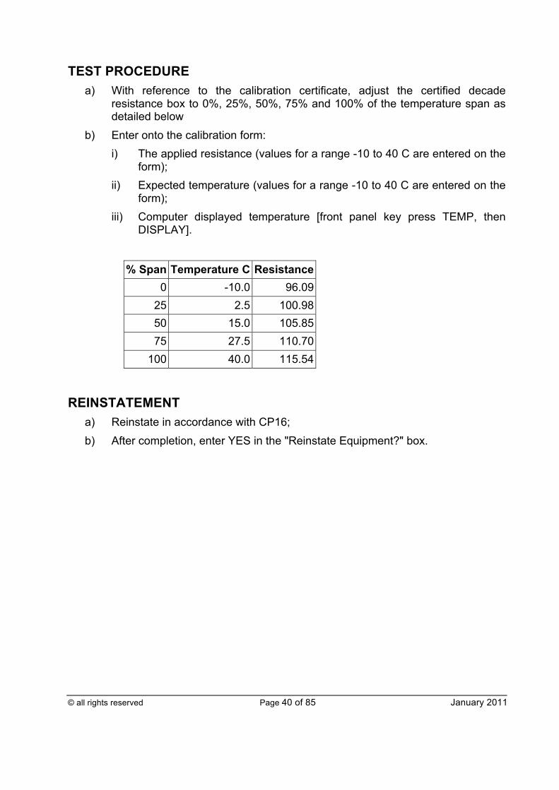
TEST PROCEDURE a) With reference to the calibration certificate, adjust the certified decade
resistance box to 0%, 25%, 50%, 75% and 100% of the temperature span as detailed below
b) Enter onto the calibration form: i) The applied resistance (values for a range -10 to 40 C are entered on the
form); ii) Expected temperature (values for a range -10 to 40 C are entered on the
form); iii) Computer displayed temperature [front panel key press TEMP, then
DISPLAY].
% Span Temperature C Resistance 0 -10.0 96.09
25 2.5 100.98 50 15.0 105.85 75 27.5 110.70
100 40.0 115.54
REINSTATEMENT
a) Reinstate in accordance with CP16; b) After completion, enter YES in the "Reinstate Equipment?" box.
© all rights reserved Page 41 of 85 January 2011
FLOW COMPUTER DAC CHECK (SITE CONTROL)
Proc No CP6a
ISSUE D
This check shall be carried out to verify the computer digital to analogue conversion accuracy by varying the output value over its operating range and comparing the measured output values with expected values generated by the computer for the volume flow signal used for Offtake control.
FREQUENCY OF TEST/CALIBRATION: Twelve (12) months
ACCEPT/REJECT: CRITERIA
± 0.1% of span
FALLBACK PROCEDURE: Check the flow computer settings. If still out of specification, recalibrate the flow computer and retest. If still out of specification, log the fault with the responsible engineering manager without delay.
PREPARATIONS/PRECAUTIONS a) The affected system operator shall be advised prior to undertaking this
procedure, in order that it may manage the operation of the Offtake and account for errors introduced to the declared the on-site telemetry flow rate.
b) It shall be noted that, when setting default values, the calculated flow within the Omni will be affected, resulting in a change in analogue outputs. The following shall be considered: i) The on-site telemetry will display a corresponding instantaneous
volumetric flow rate, which could result in unexpected valve movements if either the Offtake is not set in DVC and/or the signal to the valve has not been isolated.
ii) The LGT system shall be configured, as defined within CP6c, to prevent the injection of odorant in proportion to the simulated flow.
HOOK UP PROCEDURE Connect the Digital Multimeter (DMM) referring to the appropriate Offtake specific instrument loop diagrams.
© all rights reserved Page 42 of 85 January 2011
TEST PROCEDURE a) Put the Omni into DIAGNOSTIC mode by pressing the keys Alpha Shift,
Diag; b) Press the following keys, Output, ‘1’, Enter (please note that ‘1’ designates
the location of the analogue output); c) Scroll down to the Calibrate option then press Y, Enter; d) Determine the desired fixed value of the analogue output as a percentage of
range (note the output may be varied over the range 0 to 100%). The following example will set the output at 25%.
Enter the value by pressing keys 25, Enter; e) To validate the D/A output, set the output at 0%, 25%, 50%, 75% and 100%,
and enter the measured DMM values onto the check form; f) Reinstate the analogue loop by taking the Omni out of diagnostic mode by
pressing keys Diag, Enter.
REINSTATEMENT a) Put the flow computer back into normal operation (DISPLAY mode); b) Reinstate in accordance with CP16; c) After completion, enter YES in the "Reinstate Equipment?" box.
© all rights reserved Page 43 of 85 January 2011
TELEMETRY UNIT ADC AND ON-SITE TELEMETRY CHECK
Proc No CP6b
ISSUE D
This check shall be carried out to verify the telemetry analogue to digital conversion accuracy, by varying the output value over its operating range and comparing the displayed output values with expected values generated by the computer for the volume flow signal. The values received by the affected system operator from the on-site telemetry are also checked. NB CP6a should be performed before completing this test.
FREQUENCY OF TEST: Twelve (12) months
ACCEPT/REJECT: CRITERIA
± 0.5% of reading
FALLBACK PROCEDURE: Check all values entered and the on-site telemetry database. If still out of specification, log the fault with the responsible engineering manager without delay.
PREPARATIONS/PRECAUTIONS a) The affected system operator shall be advised prior to undertaking this
procedure, in order that it may manage the operation of the Offtake and account for errors introduced to the declared on-site telemetry instantaneous flow rate.
b) It shall be noted that, when setting default values, the calculated flow within the Omni will be affected, resulting in a change in analogue outputs. The following shall be considered: i) The on-site telemetry will display a corresponding instantaneous
volumetric flow rate, which could result in unexpected valve movements if either the Offtake is not set in DVC and/or the signal to the valve has not been isolated.
ii) The LGT system shall be configured, as defined within CP6c, to prevent the injection of odorant in proportion to the simulated flow.
TEST PROCEDURE a) Enter onto the calibration form the maximum volume flow from the flow
computer [ONLINE>OMNI CONFIGURATION>CONFIG D/A OUT>D/A OUTPUT @20mA];
© all rights reserved Page 44 of 85 January 2011
b) Put the Omni into DIAGNOSTIC mode by pressing the keys Alpha Shift, Diag;
c) Press the following keys, Output, ‘1’, Enter (Please note that ‘1’ designates the location of the analogue output);
d) Scroll down to the Calibrate option then press Y, Enter; e) Determine the desired fixed value of the analogue output as a percentage of
range (note the output may be varied over the range 0 to 100%). The following example will set the output at 25%:
Enter the value by pressing keys 25, Enter; f) To validate the D/A output, set the output at 0%, 25%, 50%, 75% and 100%,
and for each enter onto the check form: i) Telemetry Unit Volume flow (%) ii) Volume flow from the on-site telemetry (mscm/d) (contact the affected
system operator); Reinstate the analogue loop by taking the Omni out of diagnostic mode by pressing keys Diag, Enter.
REINSTATEMENT a) Put the flow computer back into normal operation (DISPLAY mode); b) Reinstate in accordance with CP16; c) After completion, enter YES in the "Reinstate Equipment?" box.
© all rights reserved Page 45 of 85 January 2011
FLOW COMPUTER DAC CHECK/MANUAL OVER-RIDE (LGT)
Proc No CP6c
ISSUE D
This procedure has been developed to: a) Verify the flow computer digital to analogue conversion accuracy by varying
the output value over its operating range and comparing the measured output values with expected values generated by the computer for the volume flow signal used for LGT. This provides a functional check on the signal to the SCIM panel; for full calibration of the NJEX controller flow input and current splitter refer to T/PM/MAINT/8;
b) Maintain the LGT system whilst working upon the meter system; c) Operate the LGT system when the meter system fails; d) Maintain the LGT system during a planned power outage.
FREQUENCY OF TEST/CALIBRATION:
Annually during meter system validation and when a manually derived odorant injection rate is required.
ACCEPT/REJECT CRITERIA:
± 0.5% of reading and gas shall be odorised in accordance with GS(M)R.
FALLBACK PROCEDURE: If the test fails check the flow computer configuration settings. If the DAC is out of specification, recalibrate the flow computer and retest. If still out of specification, log fault with the responsible engineering manager without delay. See also document T/PM/MAINT/8.
PREPARATIONS/PRECAUTIONS a) Odorant is injected into the gas in direct proportion to the instantaneous
standard volume flow rate signal derived from the flow computer. It shall be noted that the application of this procedure will result in a change in the odorant injection rate.
b) All activities that result in a change to the Omni instantaneous flow signal (analogue #2), shall be managed such that the impact upon the injection rate is limited to fifteen (15) minutes.
c) For longer periods of interruption, the injection rate shall be set via the NJEX controller as defined within T/PM/MAINT/8.
d) The following activities will determine the Omni instantaneous flow signal (analogue #2) that is input into the LGT controller.

© all rights reserved Page 46 of 85 January 2011
i) Normal operation - analogue output = F1; ii) Meter suspect - analogue output = fixed at last good value; iii) Low flow (if set) - analogue output fixed at default value (Offtake specific); iv) Omni in Maintenance mode - analogue output fixed at default value
(typical 30%); v) Forced analogue output - analogue defaults to fixed % output; vi) Loss of Omni signal – analogue fails to zero and NJEX applies failure
mode injection rate (typically 30%); vii) NJEX not set proportional to flow - analogue not applied to injection rate; viii) Loss of power – analogue fails to zero and NJEX applies failure mode
injection rate (typically 30%).
TEST PROCEDURES This procedure assumes that the LGT is connected to the Omni flow computer analogue output number 2, and may need to be modified accordingly if this is not the case.
a) To fix the odour injection rate for up to fifteen (15) minutes. Manually set the analogue value of the (4-20mA) signal to the LGT to a fixed value. Confirm that the LGT is connected to analogue output #2 and proceed as follows: i) Put the Omni into DIAGNOSTIC mode by pressing the keys Alpha Shift,
Diag; ii) Press the following keys, Output, ‘2’, Enter (Please note ‘2’ designates
the location of the analogue output); iii) Scroll down to the Calibrate option then press Y, Enter; iv) Determine the desired fixed value of the analogue output as a percentage
of range (note the output may be varied over the range 0 to 100%). The following example will set the output at 10%.
Enter the value by pressing keys 10, Enter; v) To validate the D/A output, set the output at 0%, 25%, 50%, 75% and
100%, and enter onto the results form for each increment in the volume flow reading from the LGT Standard Control Interface Module (SCIM); TB1, Terminals 21+ve & 20 -ve;
vi) Reinstate the analogue loop by taking the Omni out of diagnostic mode by pressing keys Diag, Enter.
b) To fix the injection rate for periods longer than fifteen (15) minutes:
© all rights reserved Page 47 of 85 January 2011
To manually set the LGT to a fixed value for prolonged periods and for Offtakes where the flow is calculated within the Transmitton system, the procedure detailed within T/PM/MAINT/8 ‘Maintenance of local gas treatment’ should be adhered to. In the event of a planned power outage, local operating procedures should be referred to (as appropriate) and/or a specific risk assessment should be made in order to ensure that any necessary odorant injection requirements are appropriately managed for the duration.
REINSTATEMENT a) Reinstate in accordance with CP16; b) Ensure that the Offtake is configured such that the odorant injection system
applies the instantaneous volume flow to operate the pump and that the NJEX controller is set with both controllers in proportional to flow mode;
c) With the Offtake flowing ensure that: i) The SCIM % flow reading corresponds to the Omni/Transmitton % flow
reading; ii) The affected system operator confirms that the on-site telemetry
displayed concentration is within acceptable limits; iii) All LGT alarms are clear. NB If, following the above operations, a flow cannot be applied, the Offtake
shall not be returned to operational duty until the above checks are completed.
d) Put the flow computer back into normal operation (DISPLAY mode); e) After completion, enter YES in the "Reinstate Equipment?" box; f) Make a note in the Offtake log of the work undertaken, and record details of
the fixed values applied and the duration.
© all rights reserved Page 48 of 85 January 2011
SECONDARY INSTRUMENTATION DIFFERENTIAL PRESSURE CELL SWITCH POINT CHECK (ORIFICE METER)
Proc No CP7
ISSUE D
This check shall be carried out to ensure that the switch between differential pressure cells occurs at the correct differential pressure.
FREQUENCY OF TEST: Twelve (12) months
ACCEPT/REJECT CRITERIA:
Low Range: ± 0.25% of calibrated span High Range: ± 0.25% of calibrated span.
FALLBACK PROCEDURE: Check all the data values used. Repeat the check. If still out of specification, log the fault with the responsible engineering manager without delay.
PREPARATION/PRECAUTIONS
a) The affected system operator shall be advised prior to undertaking this procedure, in order that it may manage the operation of the Offtake.
b) It shall be noted that, when setting default values, the calculated flow within the Omni will be affected, resulting in a change in the analogue outputs. The following shall be considered: i) The on-site telemetry will display a corresponding instantaneous
volumetric flow rate, which could result in unexpected valve movements, if the Offtake is not set in DVC and/or the signal to the valve has not been isolated.
ii) The LGT system shall be configured, as defined within CP6c, to prevent the injection of odorant in proportion to the simulated flow.
HOOK UP PROCEDURE a) Connect a current source and a certified current meter, referring to the
appropriate Offtake specific instrument loop diagrams. For the differential pressure cell switch up: i) Switch on current source for low DP cell and set to 4mA; ii) Switch on current source for high DP cell and set to 20mA;
© all rights reserved Page 49 of 85 January 2011
iii) Check the rising switch-over % setting (High DP select) within the Diff Pressure Set-up menu of the Omni configuration. Then calculate the corresponding current required to switch to the high cell.
b) For the differential pressure cell switch down: i) Switch on current source for low DP cell and set to 20mA; ii) Switch on current source for high DP cell and set to 20mA; iii) Check the switch-over % setting (Low DP select %) within the Diff
Pressure Set-up menu of the Omni configuration. Then calculate the corresponding current required to switch to the low cell.
TEST PROCEDURE a) Note the “in use” differential cell from the computer display [Front panel key
press DP, then DISPLAY: DPLR- low range, DPHR - high range]. b) Slowly apply a rising/falling simulated differential pressure using the relevant
current source keeping the other fixed. c) Note the applied current at the point that the “in use” differential pressure cell
changes. d) Enter the following information onto the calibration form:
i) Desired switch point (rising and falling); This is Offtake specific and should be determined by referring to the Omni flow computer configuration file ‘Diff Pressure Setup’;
ii) Measured switch point (rising and falling); iii) The low DP cell span.
REINSTATEMENT
a) Remove the test equipment and reinstate all connections; b) Reinstate in accordance with CP16; c) After completion, enter YES in the "Reinstate Equipment?" box.

© all rights reserved Page 50 of 85 January 2011
SECONDARY INSTRUMENTATION GAS PROPERTY INFORMATION CHECK (GAS CHROMATOGRAPH)
Proc No CP8a
ISSUE D
This check shall be carried out to verify that the gas composition from a chromatograph controller is transferred correctly to the flow computer.
FREQUENCY OF TEST: Twelve (12) months
ACCEPT/REJECT CRITERIA:
± 0.001% of reading.
FALLBACK PROCEDURE: Check all the data values used. Repeat the check. If still out of specification, log the fault with the responsible engineering manager without delay.
PREPARATION/PRECAUTIONS a) The affected system operator shall be advised prior to undertaking this
procedure, in order that it may manage the operation of the Offtake and account for errors introduced to the declared the on-site telemetry flow rate.
b) It shall be noted that, when setting default values, the calculated flow within the Omni will be affected, resulting in a change in the analogue outputs. The following shall be considered: i) The on-site telemetry will display a corresponding instantaneous
volumetric flow rate, which could result in unexpected valve movements, if the Offtake is not set in DVC and/or the signal to the valve has not been isolated;
ii) The LGT system shall be configured, as defined within CP6c, to prevent the injection of odorant in proportion to the simulated flow.
TEST PROCEDURE a) Obtain an analysis report from the chromatograph controller. b) Within the cycle time of the chromatograph, obtain a Product File Report from
the flow computer [ONLINE>REPORTS>PRODUCT FILE REPORT]. c) Record the following values from the analyser (Danint screen) and flow
computer onto the Results form: i) Calorific Value (dry); ii) Relative Density; iii) Gas Composition to four (4) decimal places.

© all rights reserved Page 51 of 85 January 2011
d) Note that neo-pentane and i(so)-pentane components are summed within the Danint software prior to posting to the Omni flow computer as i(so)-pentane. Data entered into the Results form under the Analyser column shall be processed in the same manner.
REINSTATEMENT a) Put the flow computer back into normal operation (DISPLAY mode); b) Reinstate in accordance with CP16; c) After completion, enter YES in the "Reinstate Equipment?" box.
© all rights reserved Page 52 of 85 January 2011
SECONDARY INSTRUMENTATION GAS PROPERTY INFORMATION CHECK (TRACKER)
Proc No CP8b
ISSUE C
This check shall be carried out to verify that the calorific value and relative density from a Tracker is transferred correctly to the flow computer.
FREQUENCY OF TEST: Twelve (12) months
ACCEPT/REJECT CRITERIA:
± 0.001% of reading.
FALLBACK PROCEDURE: Check all the data values used. Repeat the check. If still out of specification, log the fault with the responsible engineering manager without delay.
TEST PROCEDURE Verify live values provided to the Omni flow computer from the Tracker.
a) Record the following values from TRINT onto the calibration form: i) Calorific Value; ii) Relative Density.
b) Before the Tracker values are updated, record the same quantities onto the Results form from the flow computer [Front panel key press I, O (stream 1) or P (stream 2), then DISPLAY].
REINSTATEMENT a) Put the flow computer back into normal operation (DISPLAY mode); b) Reinstate in accordance with CP16.
© all rights reserved Page 53 of 85 January 2011
FLOW COMPUTER CONFIGURATION CHECK
Proc No CP9
ISSUE D
This check shall be carried out to ensure that the Omni flow computer locations contain the data required to perform all computer functions correctly by:
a) Checking each location against an “As Left” backed-up copy of the previous validated configuration file; and
b) Checking the changes to the configuration made during this validation to produce an updated version of the “As Left” configuration file.
FREQUENCY OF TEST: Twelve (12) months
ACCEPT/REJECT CRITERIA:
a) “As Found” computer configuration report to match approved previous “As Left” configuration
b) “As Left” computer configuration to include the certified and approved fixed factors.
FALLBACK PROCEDURE: Advise the responsible engineering manager of any discrepancies without delay. On instruction alter computer configuration data or approved list as required.
PREPARATION/PRECAUTIONS: a) The affected system operator shall be advised prior to undertaking this
procedure, in order that it may manage the operation of the Offtake and account for errors introduced to the declared the on-site telemetry flow rate.
b) It shall be noted that, when setting default values, the calculated flow within the Omni will be affected, resulting in a change in the analogue outputs. The following shall be considered: i) The on-site telemetry will display a corresponding instantaneous
volumetric flow rate, which could result in unexpected valve movements, if the Offtake is not set in DVC and/or the signal to the valve has not been isolated;
ii) The LGT system shall be configured, as defined within CP6c, to prevent the injection of odorant in proportion to the simulated flow.
TEST PROCEDURE a) Obtain the approved flow computer configuration data. b) Obtain calibration certificates for the meter system.
© all rights reserved Page 54 of 85 January 2011
i) For orifice meters the tube and plate certificates are required. ii) For turbine and ultrasonic meters a high pressure calibration certificate is
required. c) Obtain a list of approved fixed factors from the responsible engineering
manager for the Offtake: i) For all “Tracker only” Offtakes obtain the approved CO2 value; ii) For “Tracker only” Offtakes with orifice plate meters, obtain fixed factors
for isentropic exponent and viscosity values; iii) For Offtakes with full chromatography and orifice plate meters, obtain the
approved isentropic exponent and viscosity values; iv) For Offtakes with full chromatography and either turbine meters or
ultrasonic meters, none of these fixed factors are required. d) Where suitable and traceable dynamic, live calculations can be used at the
Offtake, the configuration, the raw data used and the calculation methods deployed shall be documented by the responsible engineering manager. Where system limitations do not allow the direct capture and logging of the actual on-site calculated values, the responsible engineering manager shall, where necessary, be able to reconstitute the values in question from the captured (and logged) raw data and flow computer configuration information.
e) Check all locations for the flow computer against the approved configuration data.
f) Enter “YES” onto the calibration form if all is correct. g) Save the resulting configuration file to the supervisory system in accordance
with Section 8 above.
“TRACKER ONLY” OFFTAKES: The responsible engineering manager shall provide (and maintain a log of) the approved fixed CO2 value to be set within the Omni flow computer at Tracker Offtakes. The value should be determined as the average value that passed through the Offtake used for the attribution of CV for the previous twelve (12) months. The fixed CO2 value shall not be entered manually into the Omni flow computer, as it will be over written on the next update cycle from the Tracker. It shall be entered into the supervisory system file by following the appropriate procedure detailed below. NB Prior to editing the CO2 values, establish the existing value in order to identify the
appropriate fields for editing. a) To edit fixed CO2 values > Tracker build 10.2+ Offtakes
i) Stop TR_VIEW, F8, F10, OK to exit; ii) Stop TR_GO, click on TR_GO on bottom task bar, Click on top right ‘x’,
OK to exit;
© all rights reserved Page 55 of 85 January 2011
iii) Start Windows Explorer from start menu bottom left; iv) Enter the DANINT folder; v) Double click on TR_GO.DAT (associate with notepad if it does not load); vi) All Tracker Offtakes are stream 3 only, so scroll along to the existing CO2
value on the 3rd line of values (this is the stream 3 line); vii) Edit the existing CO2 value to the new Offtake-specific value from the
data provided; viii) Save the file (click on the file pull down menu, then save); ix) Close the TR_GO.DAT Notepad window by clicking on the top right ‘x’; x) Restart TR_VIEW by double clicking on the TR_VIEW icon; xi) Restart TR_GO by pressing F7 on TR_VIEW; xii) Allow eight minutes and then check that the new value for CO2 has
appeared on the TR_VIEW results window; xiii) If OK start OMNICOM, from the start applications menu; xiv) Establish communications with the Omni flow computer and ‘Receive the
on line configuration’; xv) When up-loaded check the CO2 value in the Fluid Data Analysis screen; xvi) If this is in agreement with the new edited CO2 value, save the
configuration with the current date, and make a backup copy to floppy disc;
xvii) Exit OMNICOM, the update is now complete; xviii) Return the backup disc to the responsible engineering manager.
b) To edit fixed CO2 values > Tracker DOS build Offtakes i) Stop TR_INT F8, F10, F7; ii) This should take you to the DOS prompt; iii) At prompt ‘>’ type CD\DANINT and enter, to ensure you are in the
DANINT directory; iv) Now type EDIT COMPS.ST3 and enter; v) This will put up a blue edit screen with a list of numbers; vi) The CO2 value should be the 18th value in the list and is set to the
existing CO2 value; vii) Change this value to the CO2 value provided for the site; viii) Save the file – ALT F, scroll down to SAVE, return; ix) Exit the file – ALT F, scroll down to EXIT, return; now repeat the above
steps iv) to ix), but at step iv), type EDIT COMPS.GAS; x) When this second file has been edited and saved Press Ctrl Alt, Del to
reboot the computer;
© all rights reserved Page 56 of 85 January 2011
xi) TR_INT will be started with the reboot; xii) The new CO2 value should appear on the screen after one analysis (240
sec); xiii) If OK use OMNICOM on the laptop and establish communications with
the Omni flow computer; xiv) Computer then ‘Receive the on line configuration’; xv) When up-loaded check the CO2 value in the Fluid Data Analysis screen; xvi) If this is in agreement with the new edited CO2 value, save the
configuration with the current date, and make a backup copy to floppy disc;
xvii) Exit OMNICOM, the update is now complete; xviii) Return the backup disc to the responsible engineering manager.
c) All Offtakes – Isentropic exponent and viscosity
The responsible engineering manager shall provide (and maintain a log of) the approved fixed isentropic exponent and viscosity values to be set within the Omni flow computer at all Offtakes. The value should be determined as the average value that passed through the Offtake for the previous twelve (12) months. Where suitable and traceable dynamic, live calculations can be used at the Offtake, the configuration, the raw data used and the calculation methods deployed shall be documented by the responsible engineering manager. Where system limitations do not allow the direct capture and logging of the actual on-site calculated values, the responsible engineering manager shall, where necessary, be able to reconstitute the values in question from the captured (and logged) raw data and flow computer configuration information.
REINSTATEMENT a) Put the flow computer back into normal operation (DISPLAY mode); b) Make a back-up copy of the “As Left” configuration (as detailed within General
Requirements); c) Reinstate in accordance with CP16.
© all rights reserved Page 57 of 85 January 2011
SECONDARY INSTRUMENTATION GAUGE PRESSURE TRANSMITTER CALIBRATION
Proc No CP10
ISSUE D
This check shall be carried out to ensure that the pressure measurement is maintained to the required level of accuracy by applying a known pressure across the calibrated range of the transmitter and comparing the displayed output with the expected output
FREQUENCY OF TEST/CALIBRATION: Twelve (12) months
ACCEPT/REJECT CRITERIA:
± 0.2% of the calibrated span, the impulse pipes shall be intact with no leaks, self-draining and clear of any contamination. Equalisation valve is closed.
FALLBACK PROCEDURE: Check the measurements and associated data. Adjust the transmitter zero and span to bring the output within tolerance and recheck. If the test still fails, replace the transmitter. Inform the responsible engineering manager without delay
PREPARATION/PRECAUTIONS:
a) The affected system operator shall be advised prior to undertaking this procedure, in order that it may manage the operation of the Offtake and account for errors introduced to the declared the on-site telemetry flow rate.
b) It shall be noted that, when setting default values, the calculated flow within the Omni will be affected, resulting in a change in the analogue outputs. The following shall be considered: i) The on-site telemetry will display a corresponding instantaneous
volumetric flow rate, which could result in unexpected valve movements, if the Offtake is not set in DVC and the signal to the valve has not been isolated.
ii) The LGT system shall be configured, as defined within CP6c, to prevent the injection of odorant in proportion to the simulated flow.
c) Whilst depressurising the impulse pipework, debris may be projected under high pressure. Local operating procedures should be referred to (as appropriate) and/or a specific risk assessment should be made.
© all rights reserved Page 58 of 85 January 2011
HOOK UP PROCEDURE a) In the absence of dedicated test points, it may be necessary to disconnect the
impulse lines to connect the dead-weight tester. The integrity of the impulse pipes shall be established by inspection (with the system pressurised) before the calibration of the transmitter and again after reinstatement of the pipework.
b) The pressure transmitter may be connected via a block and bleed valve arrangement. Prior to operating the valve, check its porting arrangement and establish the isolation and venting arrangements.
c) Isolate the pressure transmitter being tested and vent to atmosphere. d) If isolation valves are fitted at the orifice carrier, the impulse pipeline should
then be checked for contamination. Close the isolation valves at the carrier then use the trapped pressure within the impulse pipe to blow down the lines via the drain leg. If a drain leg is not fitted, advise the responsible engineering manager that the procedure cannot be implemented and log the details in the comments field of the Results form. If evidence of contamination is found, record the details within the comments field of the record sheet and advise the responsible engineering manager. Ensure the impulse lines are clean before reconnecting the pipework.
e) Connect the dead-weight tester to the pressure transmitter and vent in accordance with the manufacturer’s instructions. Check that the dead-weight tester is level and free from vibration during the calibration activity.
f) Site a digital thermometer as close as possible to the dead-weight tester to determine the ambient temperature during the validation.
g) Connect a certified current meter in the test loop by referring to the appropriate Offtake specific instrument loop diagrams.
TEST PROCEDURE a) When the transmitter has stabilised, exercise it through three (3) full-range
traverses prior to calibration. b) Apply pressure at nominal points equivalent to 0%, 25%, 50%, 75% and 100%,
plus an over range of 125% of the calibrated transmitter span (rising and falling) and measure the current output. Record the measured values onto the calibration form. NB If the weights corresponding to the points above are not available then
other suitable points may be chosen so long as they include 0%, 100% and 125% (or above to achieve process saturation without transmitter damage). The number of points used for rising/falling shall be the same in each case. When the descending tests are carried out, the output of the dead-weight tester shall be isolated before the weights are removed.
c) Enter the following input data onto the calibration form:
© all rights reserved Page 59 of 85 January 2011
i) Local gravity correction factor (gravitational acceleration at Offtake/9.80665);
ii) Ambient temperature of the dead-weight tester during the test; iii) Calibration temperature of the dead-weight tester; iv) The temperature coefficient of the dead-weight tester (see the
manufacturer’s manual); v) Calibrated lower and upper range value of the pressure cell.
NB The local gravity correction factor as defined in (c)(i) assumes that the
dead-weight tester is certified by the manufacturer for use at 9.80665
m/s2. Where this is not the case, the local gravity correction factor is required to be modified accordingly. Further guidance is to be sought from the responsible engineering manager as necessary.
REINSTATEMENT
a) Reinstate all wiring and the pressure transmitter installation; b) Reinstate in accordance with CP16; c) After completion, enter YES in the "Reinstate Equipment?" box.
© all rights reserved Page 60 of 85 January 2011
SECONDARY INSTRUMENTATION DIFFERENTIAL PRESSURE TRANSMITTER CALIBRATION (ORIFICE METER)
Proc No CP11
ISSUE D
This check shall be carried out to ensure that differential pressure measurement is maintained to the required level of accuracy by applying known pressure across the calibrated range of the transmitter and comparing the displayed output with the expected output.
FREQUENCY OF TEST/CALIBRATION: Twelve (12) months
ACCEPT/REJECT CRITERIA:
± 0.2% of the calibrated span, the impulse pipes shall be intact with no leaks, self-draining and clear of any contamination. Equalisation valve is closed.
FALLBACK PROCEDURE: Check all data values used and repeat the check. If still out of specification, recalibrate the zero and span as described by the manufacturer. Retest. If the test still fails, contact the responsible engineering manager without delay.
PREPARATIONS/PRECAUTIONS:
a) The affected system operator shall be advised prior to undertaking this procedure, in order that it may manage the operation of the Offtake and account for errors introduced to the declared the on-site telemetry flow rate.
b) It shall be noted that, when setting default values, the calculated flow within the Omni will be affected, resulting in a change in the analogue outputs. The following shall be considered: i) The on-site telemetry will display a corresponding instantaneous
volumetric flow rate, which could result in unexpected valve movements, if the Offtake is not set in DVC and the signal to the valve has not been isolated.
ii) The LGT system shall be configured, as defined within CP6c, to prevent the injection of odorant in proportion to the simulated flow.
c) Whilst depressurising the impulse pipework, debris may be projected under high pressure. Local operating procedures should be referred to (as appropriate) and/or a specific risk assessment should be made.
© all rights reserved Page 61 of 85 January 2011
HOOK UP PROCEDURE a) The integrity of the impulse pipes shall be established by inspection (with the
system pressurised) before the calibration of the transmitter and again after reinstatement of the pipework.
b) The differential pressure transmitter may be connected via a five-way equalisation valve. Prior to operating the valve check its porting arrangement and establish the isolation, equalisation and venting arrangements. NB Some differential pressure transmitters may be damaged if full line
pressure is applied across the transmitter. c) Prior to undertaking work on the DP system check for contamination within the
impulse lines or the transmitters as follows. i) If possible arrange for the affected system operator to reduce the flow
through the meter to zero. Then confirm that the measured DP reduces to zero for all three (3) cells. If an offset is noted record the values within the HPMIS validation form, or alternative, and advise the responsible engineering manager without delay;
ii) If with zero flow through the meter, an offset is recorded, the functionality of the DP cells shall be proven, by opening the equalising valve. Any remaining offset shall be noted as above and the responsible engineering manager informed without delay;
iii) If contamination is discovered within the transmitter or the impulse pipes, it shall be removed by blowing down the impulse pipes via the drain legs. If drain legs are not fitted inform the responsible engineering manager. The suitability of the installation is proved by repeating the above procedure until the offset is reduced to zero.
d) Once the system is proven to be clear of contamination proceed with the calibration. Isolate the differential pressure transmitter being tested. Then vent the transmitters to atmosphere.
e) Connect the dead-weight tester to the differential pressure transmitter and vent in accordance with the manufacturer’s instructions. Check that the dead-weight tester is level and free from vibration during the calibration activity.
f) Site a digital thermometer as close as possible to the dead-weight tester to determine the ambient temperature during the validation.
g) Connect a certified current meter in the test loop by referring to the appropriate Offtake specific instrument loop diagrams.
TEST PROCEDURE a) When the transmitter has stabilised, exercise it through three (3) full-range
traverses prior to calibration. b) Apply a differential pressure at nominal points equivalent to 0%, 25%, 50%,
75% and 100%, plus an over range of 125% of the calibrated transmitter span
© all rights reserved Page 62 of 85 January 2011
(rising and falling) and measure the current output. Record the measured values onto the calibration form. NB If the weights corresponding to the points above are not available then
other suitable points may be chosen so long as they include 0%, 100% and 125% (or above to achieve process saturation without transmitter damage). The number of points used for rising/falling shall be the same in each case. When the descending tests are carried out, the output of the dead-weight tester shall be isolated before the weights are removed.
c) Whilst calibrating the standby transmitter the on-site telemetry end-to-end check shall be undertaken. The pass/fail criterion for this test is 0.5% as defined within CP6b. The values reported by the affected system operator shall be recorded within the comments field on the Result form. The affected system operator shall also be requested to log the results.
d) Enter the following input data onto the calibration form:
i) Local gravity correction factor (gravitational acceleration at Offtake/9.80665);
ii) Ambient temperature of the dead-weight tester during the test; iii) Calibration temperature of the dead-weight tester; iv) The temperature coefficient of the dead-weight tester (see the
manufacturer’s manual); v) Calibrated lower and upper range value of the differential pressure
transmitter. NB The local gravity correction factor as defined in (d)(i) assumes that
the dead-weight tester is certified by the manufacturer for use at 9.80665 m/s2. Where this is not the case, the local gravity correction factor is required to be modified accordingly. Further guidance is to be sought from the responsible engineering manager as necessary.
e) Then check the zero differential pressure output of the transmitter at the operating static pressure and record the current value onto the calibration sheet.
REINSTATEMENT a) Reinstate in accordance with CP16; b) After completion, enter YES in the "Reinstate Equipment?" box.
© all rights reserved Page 63 of 85 January 2011
SECONDARY INSTRUMENTATION TEMPERATURE TRANSMITTER CALIBRATION
Proc No CP12
ISSUE C
This check shall be carried out to ensure that the temperature transmitter is maintained to the required level of accuracy by applying a known resistance across the calibrated range of the transmitter and comparing the displayed output with the expected output.
FREQUENCY OF TEST/CALIBRATION: Twelve (12) months
ACCEPT/REJECT CRITERIA:
± 0.2% of the calibrated span
FALLBACK PROCEDURE: Check the measurements and associated data. Adjust transmitter zero and span to bring the output within tolerance and recheck. If the test still fails, replace the transmitter and inform the responsible engineering manager without delay.
PREPARATION/PRECAUTIONS
a) The affected system operator shall be advised prior to undertaking this procedure, in order that it may manage the operation of the Offtake and account for errors introduced to the declared the on-site telemetry flow rate.
b) It shall be noted that, when setting default values, the calculated flow within the Omni will be affected, resulting in a change in the analogue outputs. The following shall be considered: i) The on-site telemetry will display a corresponding instantaneous
volumetric flow rate, which could result in unexpected valve movements, if the Offtake is not set in DVC and/or the signal to the valve has not been isolated;
ii) The LGT system shall be configured, as defined within CP6c, to prevent the injection of odorant in proportion to the simulated flow.
HOOK UP PROCEDURE a) Connect a certified decade resistance box to the temperature transmitter in
accordance with the manufacturer’s instructions. b) Connect a certified current meter in the test loop by referring to the appropriate
Offtake specific instrument loop diagrams.
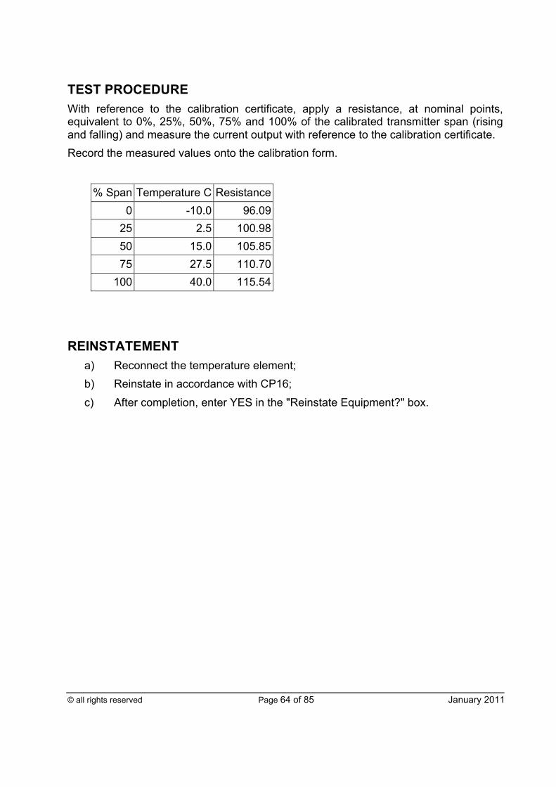
© all rights reserved Page 64 of 85 January 2011
TEST PROCEDURE With reference to the calibration certificate, apply a resistance, at nominal points, equivalent to 0%, 25%, 50%, 75% and 100% of the calibrated transmitter span (rising and falling) and measure the current output with reference to the calibration certificate. Record the measured values onto the calibration form.
% Span Temperature C Resistance 0 -10.0 96.09
25 2.5 100.98 50 15.0 105.85 75 27.5 110.70
100 40.0 115.54
REINSTATEMENT
a) Reconnect the temperature element; b) Reinstate in accordance with CP16; c) After completion, enter YES in the "Reinstate Equipment?" box.
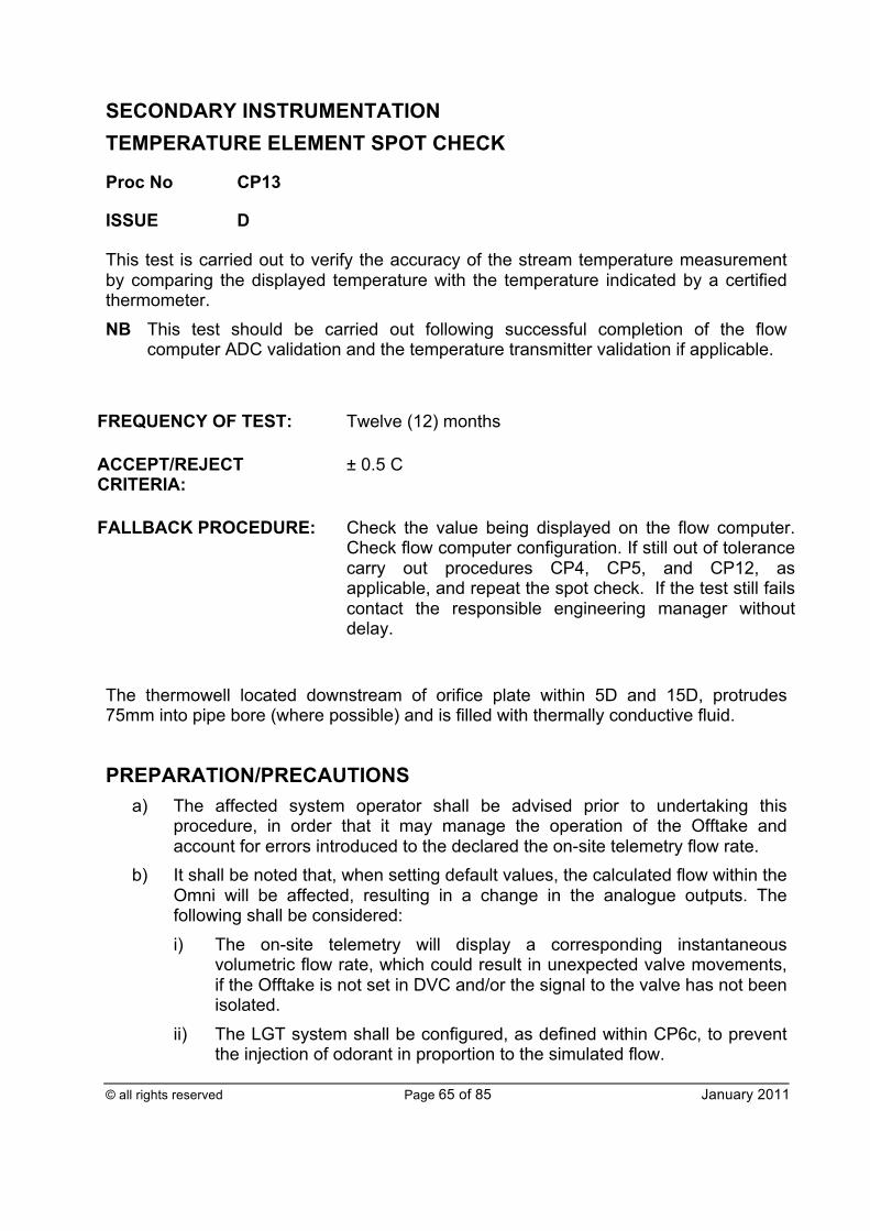
© all rights reserved Page 65 of 85 January 2011
SECONDARY INSTRUMENTATION TEMPERATURE ELEMENT SPOT CHECK
Proc No CP13
ISSUE D
This test is carried out to verify the accuracy of the stream temperature measurement by comparing the displayed temperature with the temperature indicated by a certified thermometer. NB This test should be carried out following successful completion of the flow
computer ADC validation and the temperature transmitter validation if applicable.
FREQUENCY OF TEST: Twelve (12) months
ACCEPT/REJECT CRITERIA:
± 0.5 C
FALLBACK PROCEDURE: Check the value being displayed on the flow computer. Check flow computer configuration. If still out of tolerance carry out procedures CP4, CP5, and CP12, as applicable, and repeat the spot check. If the test still fails contact the responsible engineering manager without delay.
The thermowell located downstream of orifice plate within 5D and 15D, protrudes 75mm into pipe bore (where possible) and is filled with thermally conductive fluid.
PREPARATION/PRECAUTIONS a) The affected system operator shall be advised prior to undertaking this
procedure, in order that it may manage the operation of the Offtake and account for errors introduced to the declared the on-site telemetry flow rate.
b) It shall be noted that, when setting default values, the calculated flow within the Omni will be affected, resulting in a change in the analogue outputs. The following shall be considered: i) The on-site telemetry will display a corresponding instantaneous
volumetric flow rate, which could result in unexpected valve movements, if the Offtake is not set in DVC and/or the signal to the valve has not been isolated.
ii) The LGT system shall be configured, as defined within CP6c, to prevent the injection of odorant in proportion to the simulated flow.
© all rights reserved Page 66 of 85 January 2011
TEST PROCEDURE a) Place the digital thermometer probe in the test thermowell that has previously
been filled to an appropriate level with the recommended thermally conductive fluid adjacent to the resistance thermometer device (RTD) under test. If a test thermowell is not available, place the RTD under test in a suitable water filled container together with the digital thermometer probe. The temperature element and digital thermometer probe shall be left to stabilise for a minimum of ten (10) minutes.
b) Simultaneously read then enter the following data onto the calibration form: i) Digital thermometer probe reading ii) Computer displayed temperature [Front panel key press TEMP, then
DISPLAY].
REINSTATEMENT a) Reinstate the temperature element into the thermowell and top up the thermal
conductive fluid to the approved level as necessary ; b) Reinstate in accordance with CP16; c) After completion, enter YES in the "Reinstate Equipment?" box.
© all rights reserved Page 67 of 85 January 2011
PRIMARY INSTRUMENTATION ORIFICE METER INSPECTION/REPLACEMENT
Proc No CP14a
ISSUE D
This check shall be carried out to verify that the orifice plate and carrier are maintained in good condition and are in compliance with the calibration certificate.
FREQUENCY OF TEST: All plates shall be replaced no less frequently than once every twelve (12) months. If the plate fails the calibration procedure, it shall be replaced every quarter until it passes. Thereafter replace annually. Inspections should be performed as part of ad-hoc Offtake audits.
ACCEPT/REJECT CRITERIA:
All relevant details within the flow computer shall match the tube and plate certificates. The orifice carrier shall be clean and the orifice plate shall be clean, flat, undamaged and comply with its current calibration certificate. If the meter system fails the ‘accept’ criteria, it may result in the mis-measurement of gas. In addition to recording the details (as defined within this procedure) the responsible engineering manager shall be informed without delay in order that the extent of meter errors may be assessed. All plates shall be calibrated prior to installation. Plates should be calibrated shortly after removal from service, before being placed in storage for application next year. If a plate (that has been removed from service) fails calibration, the following actions shall be implemented.
a) The plate shall be removed from further service if remedial work cannot be undertaken;
b) The responsible engineering manager shall be informed without delay;
c) The meter error shall be assessed and a meter error report produced if necessary;
d) The suitability of the meter system shall be assessed and, if appropriate, a new plate manufactured.
FALLBACK PROCEDURE: Replace the orifice plate, repair or clean the meter system and inform the responsible engineering manager without delay.
© all rights reserved Page 68 of 85 January 2011
PREPARATION/PRECAUTIONS In addition to the general preparations/precautions the following also apply:
a) A complete set of spares shall be available for the orifice plate and carrier prior to starting the checks.
b) A copy of the calibration certificate for the replacement orifice plate/plates shall be available at the Offtake. The orifice plate calibration certificate shall have a separate summary sheet detailing in bold: i) The Offtake; ii) Plate serial number; iii) Calibration date; iv) Data that is to be entered into the flow computer (certified bore and
calibration temperature). c) Lifting operations associated with lifting orifice plates in and out of pipes and
during transit to and from the Offtake shall be assessed. d) Waste oil and grease drained or cleaned from instrumentation systems shall
be contained and disposed of in a controlled manner. Whilst depressurising the impulse pipework, debris may be projected under high pressure. Local operating procedures should be referred to (as appropriate) and/or a specific risk assessment should be made. e) Prior to commencing work ensure that:
i) The direction of gas flow is identified so as to ensure the downstream side of the orifice plate is installed facing downstream;
ii) The certified bore diameter and calibrated temperature that shall be applied within the flow computer should be determined from the plate calibration certificate;
iii) The replacement orifice plate downstream face is clearly marked; iv) The replacement orifice plate is engraved with its serial number, which
matches the details on the certificate; v) On multi-stream Offtakes the meter stream identity shall be established,
to ensure that any modifications to the flow computer configuration correspond to the appropriate changes in the field.
TEST PROCEDURE a) Enter the following data into the HPMIS calibration form, or alternative, for both
the plate which is removed from service and the plate which is installed if appropriate:
© all rights reserved Page 69 of 85 January 2011
NB Where the Transporter’s agreed routine validation tool is HPMIS and access to it cannot be established on the day of work, a fall-back position using suitable spreadsheets shall be authorised by the responsible engineering manager. Upon completion of the validation work, the data held within these spreadsheets, along with the actual dates of tests, shall be transferred promptly into HPMIS to provide further data parsing and to form the official record. Where the Transporter’s agreed normal validation tool takes the form of a series of approved standalone spreadsheets, access difficulties and any necessary associated fall-back should not be a concern. To safeguard against possible corruption during use however, clean copies of the approved sheets shall be retained for standby use. Such sheet should be suitably locked down to prevent unauthorised interference and inappropriate alteration.
i) Manufacturer; ii) Serial number; iii) Certified bore; iv) Calibration temperature; v) Orifice plate certifying authority; vi) Certificate number; vii) Certificate date.
b) The removed orifice plate shall be visually inspected and checked. The plate’s
orientation and condition shall be noted on the Results form (as detailed below). Take digital photographs and forward them to the responsible engineering manager. A note detailing the Offtake/meter reference/plate serial number and date and flow direction shall be placed next to the plate when taking the picture. An object such as a ruler should be included to provide scaling.
c) Note whether the orifice plate has sustained any damage on the upstream edge of the orifice bore. This shall be square edged, and without any wire edges, burrs or visible defects.
d) Note whether the upstream face of the orifice plate appears flat and that it was correctly installed with the engraved downstream face pointing downstream
e) Visually inspect the orifice fitting noting whether areas of corrosion are present. f) Visually inspect the orifice carrier, seal ring, and top cover-plate and gasket.
Any damage shall be repaired and the details recorded within the comments filed in the Results form.
g) When single chamber orifice carriers are depressurised to remove the orifice plate, the chamber shall be inspected to determine if any contamination is
© all rights reserved Page 70 of 85 January 2011
present. Note that the action of removing the plate will result in such liquids settling within the bottom of the pipe and carrier.
h) Once depressurised, orifice carriers that are contaminated shall be cleaned and the details recorded within the comments field of the Results form. All contamination shall be disposed in accordance with the relevant COSHH handling procedure(s).
i) The following data shall be recorded within the comments field of the Results form: i) Orientation of orifice plate within the carrier; ii) Whether the orifice plate carrier operation is satisfactory; iii) Visually inspected conditions of the orifice plate; iv) Comments pertinent to the conditions of the orifice plate and carrier; v) If the plate is contaminated (coatings of grease, oil or deposits): Record
the details in the comments field - of the area covered, depth and texture of the deposits. The plate shall be cleaned as necessary using a soft cloth and a suitable solvent taking care not to damage the upstream face and square edge of the plate.
j) If a new plate is installed, the following details shall be entered onto the Data Modification section of the Results form: i) If the maximum flow rate needs to be modified, enter YES in the “Station
Flow Max Change?” field and enter the value in the “New Station Maximum Flow field”;
ii) If the pulse significance needs to be modified, enter YES in the “Pulse Significance Change?” field and enter the value in the “New Pulse Significance” field.
k) The flow computer configuration shall be checked to ensure that it has the correct data for: i) New station maximum flow rate (scm/hr) for the on-site telemetry and
LGT; ii) New pulse significance (pulses/unit); iii) New certified orifice bore to four (4) decimal places (mm). For multi-
stream Offtakes it is important to ensure that the appropriate meter configuration data field is edited to match the hardware changes;
iv) New certified temperature; v) New low and high differential pressure span (mbar); vi) If the configuration has been changed, enter YES in the appropriate field
when the flow computer has been updated. NB Whilst editing the flow configuration file via OmniCom, the Danint window
may become active. This occurs when the chromatograph data is read from its controller. The site operative shall take care whilst editing the
© all rights reserved Page 71 of 85 January 2011
Omni configuration file to ensure that the details are logged within the flow computer. If the Danint window becomes active whilst entering data into OmniCom, the site operative shall click the mouse onto the OmniCom window in order to make it the active window.
l) The affected system operator shall be informed of the changes and YES shall be entered in the “ACC Informed?” field: i) If the maximum station flow rate has changed, the NJEX controller for
Local Gas Treatment shall be updated. Enter the new maximum flow rate in the controller in scm/s. Enter YES in the “NJEX controller updated?” field when completed;
ii) The telemetry unit labels, records and configuration may need to be updated with the new max flow, new standby DP span, new high alarm limits and new flow set point range. Enter YES in the “Telemetry Unit Updated?” field when completed;
iii) Other associated equipment may need updating. Enter YES in the “Other Signals Updated?” field when completed.
NB This generic field is to remind the on-site engineer to think about other affected systems specific to the Offtake.
NB The removed orifice plate shall be returned to an appropriate facility within
fourteen (14) days for annual re-certification. If a plate fails the re-certification process, the appropriate facility shall advise the responsible engineering manager.
REINSTATEMENT a) Reinstate all the equipment; b) Reinstate in accordance with CP16; c) After completion, enter YES in the "Reinstate Equipment?" box.
© all rights reserved Page 72 of 85 January 2011
PRIMARY INSTRUMENTATION TURBINE METER INSPECTION/REPLACEMENT/MAINTENANCE
Proc No CP14b
ISSUE D
This check shall be carried out to verify that the turbine meter is maintained in good condition and is in compliance with the calibration certificate.
FREQUENCY OF TEST/CALIBRATION: Twelve (12) months
FREQUENCY OF LUBRICATION:
Suitable oil shall be applied to the bearings of lubricated meters in accordance with manufacturers’ guidance. Where such guidance is not available, suitable oil shall be applied to the bearings of lubricated meters every four (4) months
ACCEPT/REJECT CRITERIA:
The turbine meter shall be undamaged and comply with its current calibration certificate. The k-factors and corresponding frequency points applied within the flow computer shall be traceable back to its high-pressure natual gas calibration certificate. If the meter system fails the accept criteria, it may result in the mis-measurement of gas. In addition to recording the details (as defined within this procedure) the appropriate responsible engineering manager shall be informed in order that the extent of meter errors may be assessed. All pulses generated by the turbine meter shall be recorded within the Omni flow computer.
FALLBACK PROCEDURE: Repair/replace the turbine meter and inform the responsible engineering manager without delay.
PREPARATION/PRECAUTIONS
a) The affected system operator shall be advised prior to undertaking this procedure, in order that it may manage the operation of the Offtake and account for errors introduced to the declared the on-site telemetry flow rate.
© all rights reserved Page 73 of 85 January 2011
b) It shall be noted that, when setting default values, the calculated flow within the Omni will be affected, resulting in a change in the analogue outputs. The following shall be considered: i) The on-site telemetry will display a corresponding instantaneous
volumetric flow rate, which could result in unexpected valve movements, if the Offtake is not set in DVC and/or the signal to the valve has not been isolated.
ii) The LGT system shall be configured, as defined within CP6c, to prevent the injection of odorant in proportion to the simulated flow.
In addition to these general preparations/precautions, the following also apply:
a) Obtain (and check) a copy of the calibration certificate for the meter; b) Lifting operations associated with lifting meters in and out of pipes and during
transit to and from the Offtake shall be assessed; c) Waste oil and grease drained or cleaned from instrumentation systems shall
be contained and disposed of in a controlled manner; d) Whilst depressurising the impulse pipework, debris may be projected under
high pressure. Local operating procedures should be referred to (as appropriate) and/or a specific risk assessment should be made.
e) Suitable new gaskets shall be available in the event of immediate replacement being necessary.
TEST PROCEDURE a) Obtain a current high-pressure calibration certificate for the turbine meter:
i) Lubricated meters shall be recalibrated every twelve (12) years; ii) Non-lubricated meters shall be recalibrated every eight (8) years.
b) If a meter has been calibrated with air at low pressure or if the certificate is no longer current the meter shall be removed and recalibrated in accordance with ISO 9951 at a suitably accredited facility. The following exception applies:- For Offtakes with a single stream, where the Offtake cannot be isolated the responsible engineering manager if necessary, shall provide a calibrated replacement meter. This is so that the meter may be removed, recalibrated and made available for another single stream Offtake.
c) Enter the following data onto the calibration form for both the turbine meter, which is removed from service, and the new turbine meter if appropriate: i) Manufacturer; ii) Serial number; iii) K-factors and corresponding frequency points; iv) Maximum flow rate;
© all rights reserved Page 74 of 85 January 2011
v) Minimum flow rate; vi) Maximum pressure; vii) Certifying authority; viii) Certificate number; ix) Certificate date.
d) The turbine meter shall be inspected by applying the following procedure: i) Check the direction of flow through the turbine meter is correct; ii) Using an oscilloscope or frequency counter confirm (with gas flowing)
that the number of pulses (frequency) generated by the meter pickup corresponds with that recorded by the Omni flow computer. Record the results in the comments section within HPMIS, or alternative. Check that all the impellors are detected on the turbine wheel by checking the profile of the pulse train;
Remove the turbine meter from the pipeline following detailed instructions where appropriate (in accordance with T/PM/MAINT8). NB Whilst depressurising the line, restrict the rate of venting such that the
meter speed does not exceed Qmax; iii) Visually inspect the turbine meter casing and rotors for evidence of
damage or contamination and enter the required data onto the validation form;
iv) Visually inspect the pipe (from which the meter was removed) for evidence of contamination. If liquid or solid deposits are found record the details of the nature of and extent of the contamination within the comments section of the Record form and notify the asset owner;
v) Spin test the meter as follows :
• Where possible, transfer the meter to a draught free room and support the meter in the same plane as that for its normal operation (for lubricated meters do not apply oil prior to the test);
• Where this is not possible due to lifting difficulties or obstruction/lack of space, all reasonable precautions shall be taken to conduct the test during calm weather conditions. Consideration to the erection of temporarily wind breaks should otherwise be given.
• Accelerate the meter just above 10% of Qmax by, for instance, applying compressed nitrogen;
• Switch off the nitrogen jet, or equivalent, and record the time within HPMIS, or alternative, taken for the meter to reduce to 1Hz by, for example, recording the output of the meter on a suitable frequency meter;
• Repeat the test two (2) more times;
• Fit the meter back into the pipe and re-commission in accordance with T/PM/MAINT/8.

© all rights reserved Page 75 of 85 January 2011
NB Whilst pressurising the line the rate of gas flow shall be restricted such that the meter speed does not exceed Qmax.
NB Whilst inspecting and testing the turbine meter, if any damage is observed, the fault shall be logged with the responsible engineering manager
e) If a new meter is installed, enter the following details onto the ‘Data Modification’ section of the Results form: i) If the maximum flow rate needs to be modified, enter YES in the “Station
Flow Max Change?” field and enter the value in the “New Station Maximum Flow” field;
ii) If the pulse significance needs to be modified, enter YES in the “Pulse Significance Change?” field and enter the value in the “New Pulse Significance” field;
iii) The flow computer may need updating with:
• New station maximum flow rate (scm/hr) for the on-site telemetry and LGT;
• New pulse significance (pulses/unit);
• New K-Factors (pulses/m3) and corresponding frequency points (Hz);
• Enter YES in the appropriate field when the flow computer has been updated (see GMR5);
iv) The on-site telemetry may need updating with:
• Maximum flow rate (mscm/d);
• Pulse significance (pulses/scm);
• New high alarm limits (mscm/d);
• New flow set point range (mscm/d);
• Ensure that the affected system operator has been informed of the changes and then enter YES in the “ACC Informed?” field;
v) If the maximum station flow rate has changed, the NJEX controller for Local Gas Treatment shall be updated. Enter the new maximum flow rate in the controller in scm/s. Enter YES in the “NJEX Controller Updated?” field when completed;
vi) The telemetry unit labels, records and configuration may need to be updated. Enter YES in the “Telemetry Unit Updated?” field when completed;
vii) Other associated equipment may need updating. Enter YES in the “Other Signals Updated?” field when completed.
NB This generic field is aimed at reminding the on-site engineer to think about other affected systems specific to the Offtake.
© all rights reserved Page 76 of 85 January 2011
REINSTATEMENT
a) Reinstate the turbine meter and apply oil to the bearings of lubricated meters; b) Manufacturer’s recommended installation procedures shall be adhered to; this
is likely to include mounting bolt tightening sequence and associated torque settings.
b) Reinstate in accordance with CP16; c) After completion, enter YES in the "Reinstate Equipment?" box.
© all rights reserved Page 77 of 85 January 2011
PRIMARY INSTRUMENTATION ULTRASONIC METER INSPECTION/REPLACEMENT/MAINTENANCE
Proc No CP14c
ISSUE C
This check shall be carried out to verify that the ultrasonic meter is maintained in good condition and is traceable to its calibration certificate.
FREQUENCY OF TEST: Twelve (12) months
ACCEPT/REJECT CRITERIA:
The ultrasonic meter shall be undamaged and comply with its current calibration certificate, with all transducers operating within defined limits and the measured velocity of sound (VOS) matching the calculated value. If the meter is damaged or does not perform satisfactorily, the responsible engineering manager shall be informed without delay
FALLBACK PROCEDURE: Repair/replace the ultrasonic meter and inform the responsible engineering manager without delay.
PREPARATION/PRECAUTIONS
a) The affected system operator shall be advised prior to undertaking this procedure, in order that it may manage the operation of the Offtake and account for errors introduced to the declared the on-site telemetry flow rate.
b) It shall be noted that, when setting default values, the calculated flow within the Omni will be affected, resulting in a change in the analogue outputs. The following shall be considered: i) The on-site telemetry will display a corresponding instantaneous
volumetric flow rate, which could result in unexpected valve movements, if the Offtake is not set in DVC and/or the signal to the valve has not been isolated.
ii) The LGT system shall be configured, as defined within CP6c, to prevent the injection of odorant in proportion to the simulated flow.
In addition to these general preparations/precautions, the following will also apply:
a) Obtain (and check) a copy of the calibration certificate for the meter;
© all rights reserved Page 78 of 85 January 2011
b) Lifting operations associated with lifting meters in and out of pipes and during transit to and from the Offtake shall be assessed;
c) Waste oil and grease drained or cleaned from instrumentation systems shall be contained and disposed of in a controlled manner;
d) Whilst depressurising the impulse pipework, debris bay be projected under high pressure. Local operating procedures should be referred to (as appropriate) and/or a specific risk assessment should be made.
e) Suitable new gaskets shall be available in the event of immediate replacement being necessary.
If the meter fails to meet the test criteria, it may be necessary to remove one or more probes for inspection or replacement. Note that the probes are under pressure. If the meter is designed such that it is possible to extract the probes whilst under pressure the site operators shall ensure that:
a) The required tools are available; b) A procedure is available; c) They are trained.
Once removed, the probes should be inspected to ensure that they are undamaged and free from contamination or corrosion. In order to preserve meter integrity, it is important that each probe/cable shall be replaced in its original port. NB At this point it is advisable to carry out the appropriate steps of the procedures
below, again to ensure the action of removing and returning probes has not affected the meter performance.
TEST PROCEDURES The meter shall have a valid calibration certificate. If the meter does not have a current certificate then the meter shall be removed and calibrated. Additional testing should be carried out. There is a choice of two (2) test procedures, which increase in complexity and cost. If the Basic Test cannot be implemented, the responsible engineering manager shall be advised who will provide instruction whether to proceed to the Full Test. The Basic Test can be carried out with the meter in situ and will indicate if the meter is operating satisfactorily at an operational level. This will not indicate if the bore is contaminated or damaged. A more thorough test involves removing the meter from the line. This is required if zero flow across the meter cannot be guaranteed. In this case, it is also possible to check for damage or contamination of the meter that may affect performance that would not be detected in the Basic Test.
© all rights reserved Page 79 of 85 January 2011
a) Basic Test i) Communicate with the USM from the Omni by PRESSING [Meter] [N]
[Display] and [Setup] [N] [Display]; ii) Note the test conditions, ie gas composition, temperature, pressure; iii) Record the following data for each transducer (for entry into HPMIS, or
equivalent) which will calculate the pass/fail status of the meter: § Transducer ID and corresponding serial number; § Transducer performance; § No of valid samples; § AGC; § AGC limit; § VOS.
iv) Record the overall performance of the USM; v) Obtain a measurement of the velocity of sound (using Danint) for the gas
composition used in the test by an independent means. Ensure the velocities of sound for the chords agree with each other and the independent value and are within the parameters recommended as acceptable by the meter manufacturer;
vi) Check that the cables from the probes are in good condition; vii) Ensure the correct probes (by serial number) are in the correct ports (as
designated by the most recent installation data sheet); viii) Using the manufacturer’s software make a backup copy of the USM
configuration.
b) Full Test i) Remove the meter from the line; ii) Check that the meter bore is undamaged and free from contamination or
corrosion; iii) Place the meter in a temperature controlled environment or thoroughly
lag the meter; iv) Seal both ends of the meter using blocking flanges; v) Fill the meter with nitrogen, to a pressure of 20 bar; vi) Allow the meter to thermally stabilise; vii) Note the test conditions, ie temperature, pressure; viii) Check the meter diagnostics and note down for each chord: the gain,
flow rate and velocity of sound;

© all rights reserved Page 80 of 85 January 2011
ix) Check that for each chord, the gain and the flow measurements are within the parameters recommended as acceptable by the meter manufacturer. This is for zero flow at the given gas composition, temperature and pressure;
x) Obtain a measurement of the velocity of sound for the gas composition used in the test by an independent means. Ensure the velocities of sound for the chords agree with each other and the independent value is within that recommended as being acceptable by the meter manufacturer;
xi) Check that the cables from the probes are in good condition; xii) Ensure the correct probes (by serial number) are in the correct ports (as
designated by the most recent data installation sheet); xiii) If satisfactory return the meter to the line. Ensure the orientation is as
before.
REINSTATEMENT a) Manufacturer’s recommended installation procedures shall be adhered to;
this is likely to include mounting bolt tightening sequence and associated torque settings.
b) Reinstate in accordance with CP16; c) After completion, enter YES in the "Reinstate Equipment?" box.
© all rights reserved Page 81 of 85 January 2011
REINSTATEMENT CHECK
Proc No CP16
ISSUE C
This procedure has been developed to support the reinstatement of the metering system following modifications introduced during maintenance activities. NB In order to validate the meter system, a number of modifications will have to be
made. These comprise both disconnecting physical instruments (or wires) and software edits. Upon completion of the validation, the system shall be reinstated.
This procedure identifies the modifications introduced during each procedure. It is intended as a guide to ensure that the modifications are removed and the system is reinstated. Following the site works associated with the validation, the appropriate reinstatement checks CP1 to CP14 shall be recorded within this procedure. The application of procedure CP17 shall be undertaken and recorded by the appropriate facility.
FREQUENCY OF TEST:
Following the application of one (1) or more validation procedures.
ACCEPT/REJECT CRITERIA:
A metering or LGT error has not been introduced. The Offtake activities associated with the meter validation have been completed. The responsible engineering manager shall be informed if one or more of the reinstatement checks fail.
FALLBACK PROCEDURE: None.
Procedure Reinstatement check to be undertaken Name/date CP1a Modbus address
reset to 1 TE, PT and DPT over-ride = 3
Confirm live composition is transferred into Omni
CP1b Modbus address reset to 1
TE, PT and DPT over-ride = 3
Confirm live composition is transferred into Omni
CP2a Modbus address reset to 1
TE, PT and DPT over-ride = 3
CP2b Modbus address reset to 1
TE and PT over-ride = 3
Confirm the live frequency is applied within the Omni
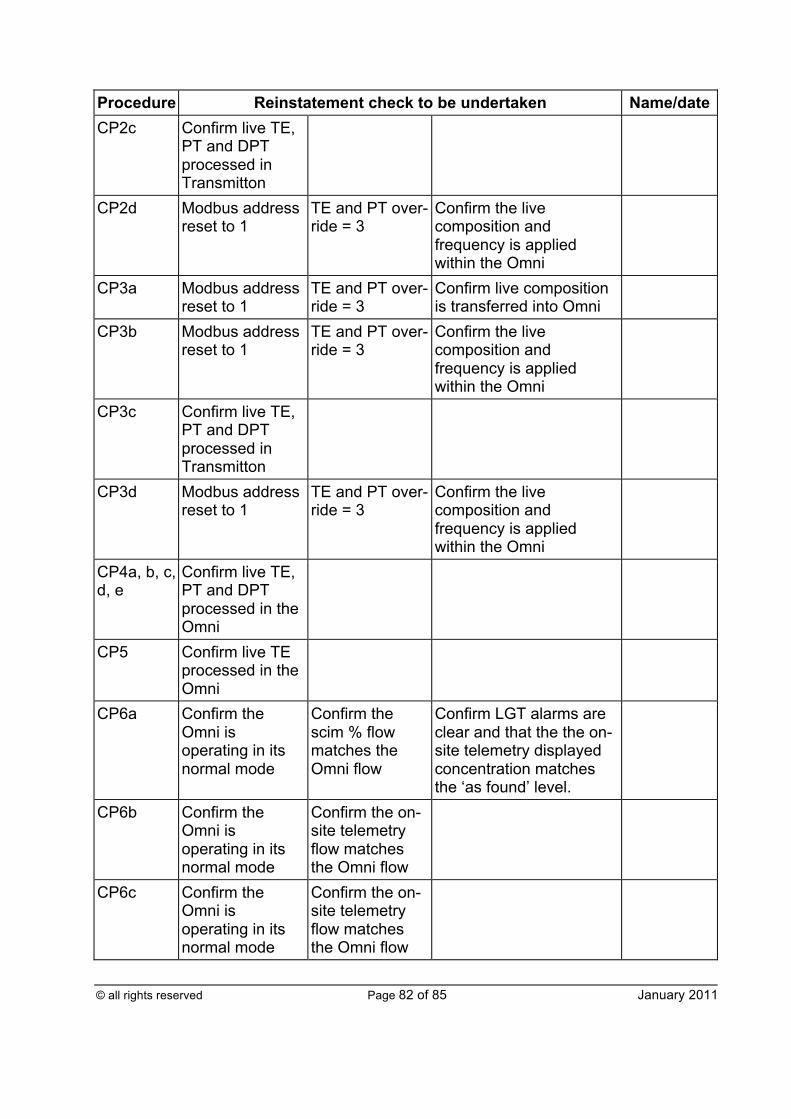
© all rights reserved Page 82 of 85 January 2011
Procedure Reinstatement check to be undertaken Name/date CP2c Confirm live TE,
PT and DPT processed in Transmitton
CP2d Modbus address reset to 1
TE and PT over-ride = 3
Confirm the live composition and frequency is applied within the Omni
CP3a Modbus address reset to 1
TE and PT over-ride = 3
Confirm live composition is transferred into Omni
CP3b Modbus address reset to 1
TE and PT over-ride = 3
Confirm the live composition and frequency is applied within the Omni
CP3c Confirm live TE, PT and DPT processed in Transmitton
CP3d Modbus address reset to 1
TE and PT over-ride = 3
Confirm the live composition and frequency is applied within the Omni
CP4a, b, c, d, e
Confirm live TE, PT and DPT processed in the Omni
CP5 Confirm live TE processed in the Omni
CP6a Confirm the Omni is operating in its normal mode
Confirm the scim % flow matches the Omni flow
Confirm LGT alarms are clear and that the the on-site telemetry displayed concentration matches the ‘as found’ level.
CP6b Confirm the Omni is operating in its normal mode
Confirm the on-site telemetry flow matches the Omni flow
CP6c Confirm the Omni is operating in its normal mode
Confirm the on-site telemetry flow matches the Omni flow
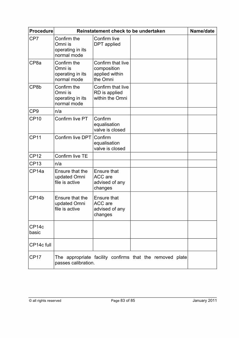
© all rights reserved Page 83 of 85 January 2011
Procedure Reinstatement check to be undertaken Name/date CP7 Confirm the
Omni is operating in its normal mode
Confirm live DPT applied
CP8a Confirm the Omni is operating in its normal mode
Confirm that live composition applied within the Omni
CP8b Confirm the Omni is operating in its normal mode
Confirm that live RD is applied within the Omni
CP9 n/a CP10 Confirm live PT Confirm
equalisation valve is closed
CP11 Confirm live DPT Confirm equalisation valve is closed
CP12 Confirm live TE CP13 n/a CP14a Ensure that the
updated Omni file is active
Ensure that ACC are advised of any changes
CP14b Ensure that the updated Omni file is active
Ensure that ACC are advised of any changes
CP14c basic
CP14c full
CP17 The appropriate facility confirms that the removed plate passes calibration.
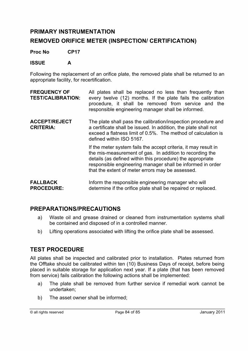
© all rights reserved Page 84 of 85 January 2011
PRIMARY INSTRUMENTATION REMOVED ORIFICE METER (INSPECTION/ CERTIFICATION)
Proc No CP17
ISSUE A
Following the replacement of an orifice plate, the removed plate shall be returned to an appropriate facility, for recertification.
FREQUENCY OF TEST/CALIBRATION:
All plates shall be replaced no less than frequently than every twelve (12) months. If the plate fails the calibration procedure, it shall be removed from service and the responsible engineering manager shall be informed.
ACCEPT/REJECT CRITERIA:
The plate shall pass the calibration/inspection procedure and a certificate shall be issued. In addition, the plate shall not exceed a flatness limit of 0.5%. The method of calculation is defined within ISO 5167. If the meter system fails the accept criteria, it may result in the mis-measurement of gas. In addition to recording the details (as defined within this procedure) the appropriate responsible engineering manager shall be informed in order that the extent of meter errors may be assessed.
FALLBACK PROCEDURE:
Inform the responsible engineering manager who will determine if the orifice plate shall be repaired or replaced.
PREPARATIONS/PRECAUTIONS
a) Waste oil and grease drained or cleaned from instrumentation systems shall be contained and disposed of in a controlled manner.
b) Lifting operations associated with lifting the orifice plate shall be assessed.
TEST PROCEDURE All plates shall be inspected and calibrated prior to installation. Plates returned from the Offtake should be calibrated within ten (10) Business Days of receipt, before being placed in suitable storage for application next year. If a plate (that has been removed from service) fails calibration the following actions shall be implemented:
a) The plate shall be removed from further service if remedial work cannot be undertaken;
b) The asset owner shall be informed;
© all rights reserved Page 85 of 85 January 2011
c) The meter error shall be assessed and a meter error report produced if necessary;
d) The suitability of the meter system shall be assessed and if appropriate a new plate manufactured.
Each plate shall be engraved with its serial number and have its downstream face clearly marked. Following calibration, a copy of the calibration certificate shall be sent to the responsible engineering manager and the appropriate site operative(s). The facility representative shall enter the following details into HPMIS, or alternative:
a) The plate serial number; b) The certified bore; c) The calibration temperature; d) The certified plate thickness; e) Drain hole details (if any).
REINSTATEMENT
a) The certified data associated with the orifice plate shall be entered into HPMIS, or equivalent;
b) Record the calibration pass status of the plate within CP16; c) The calibrated plate shall be stored in a suitable environment until it is
dispatched to the appropriate site operative for use at the appropriate Offtake meter.