Embed Size (px)
Citation preview
Redis
Validity of the sonar equation and Babinet’s principlefor scattering in a stratified medium
Purnima Ratilal, Yisan Lai, and Nicholas C. Makrisa)
Massachusetts Institute of Technology, Cambridge, Massachusetts 02139
~Received 27 July 2001; revised 8 April 2002; accepted 12 June 2002!
The sonar equation rests on the assumption that received sound pressure level after scattering can bewritten in decibels as a sum of four terms: source level, transmission loss from the source to thetarget, target strength, and transmission loss from the target to the receiver. This assumption isgenerally not valid for scattering in a shallow water waveguide and can lead to large errors andinconsistencies in estimating a target’s scattering properties as well as its limiting range of detection.By application of coherent waveguide scattering theory, the sonar equation is found to becomeapproximately valid in a shallow water waveguide when the object’s complex scatter function isroughly constant over the equivalent horizontal grazing angles6Dc spanned by the dominantwaveguide modes. This is approximately true~1! for all objects of spatial extentL and wavelengthl when 2Dc,l/2L and ~2! for spheres and certain other rounded objects in nonforward scatterazimuths, even when~1! does not hold. The sonar equation may be made valid by lowering theactive frequency of operation in a waveguide. This is often desirable because it greatly simplifies theanalysis necessary for target classification and localization. Similarly, conditions are given for whenBabinet’s principle becomes approximately valid in a shallow water waveguide. ©2002Acoustical Society of America.@DOI: 10.1121/1.1499136#
PACS numbers: 43.30.Ft, 43.30.Gv, 43.30.Vh@DLB#
ica
i
thasthlorts
ete
anccrgar
aa
de
einoaan
tpli-
owrterat-er-tity,from
,
pa-ceare
d ofave
as a
ac-of-and
owons
uepli-in-
int
I. INTRODUCTION
The sonar equation is the most widely used analyttool in applications of active sonar.1–5 It is typically em-ployed to estimate a target’s scattering properties and liming range of detection.1 The sonar equation, in its active formfor an omnidirectional source, rests on the assumptionreceived sound pressure level in decibels can be writtensum of four terms: source level, transmission loss fromsource to the target, target strength, and transmissionfrom the target to the receiver. This assumption has twolated implications:~1! that propagation and scattering effecare completely factorable from each other, and~2! that alinear combination of the incoherent quantities, targstrength, transmission loss, and source level complespecifies the sound pressure level at the receiver.
When this assumption is axiomatically adopted inocean waveguide, fundamental inconsistencies can owhen experimental data is examined. For example, the tastrength of an object, which should be invariant, can vsignificantly with range when experimentally estimated inrange-independent environment where the direct returnrives together with multiple returns from the waveguiboundaries. This has been noted in the classic text,Physics ofSound in the Sea.2 Regardless of this inconsistency, targstrength is still used in that text to describe the scatterproperties of an object because a more fundamental apprhad not presented itself, just as it is still used today by mpractitioners of ocean acoustics.
a!Electronic mail: [email protected]
J. Acoust. Soc. Am. 112 (5), Pt. 1, Nov. 2002 0001-4966/2002/112(5)/1
tribution subject to ASA license or copyright; see http://acousticalsociety.or
l
t-
ata
ess
e-
tly
urety
r-
tgchy
Our goal in the present paper is to~1! demonstrate thathe assumption that the sonar equation rests on and its imcations are not generally valid for scattering in a shallwater waveguide, and~2! provide conditions necessary fothe sonar equation to become valid in a shallow wawaveguide.6 In the process we show that the invariant sctering properties of an object in a waveguide cannot genally be described by target strength, an incoherent quanbut rather require a coherent representation that arisesthe fundamental waveguide scattering theory7,8 upon whichour analysis is based.
First developed in World War II,1,2 the sonar equationanalogous to the radar equation,is only valid when propaga-tion and scattering dependencies are approximately serable. For example, given an omnidirectional point sourand receiver in free space, propagation and scatteringseparable when the source and receiver are in the farfielthe target, where the incident as well as the scattered wmay be approximated as planar. The sonar equation hlong history of legitimate usage in deep water,1,2 where thesefree-space conditions are effectively achieved in many prtical scenarios due to the significant time separation thatten occurs between direct and surface reflected arrivalsthe adiabatic nature of refraction in the ocean.
In continental shelf environments, referred to as shallwater waveguides in ocean acoustics, multiple reflectifrom the surface and bottom typically overlap andcoherentlyinterfere with each other and the direct arrival. No uniqincident and scattered angle exists. To understand the imcations for scattering, it is convenient to decompose thecident field at a target in a waveguide from a farfield po
1797797/20/$19.00 © 2002 Acoustical Society of America
g/content/terms. Download to IP: 18.38.0.166 On: Mon, 12 Jan 2015 17:32:25
avo
haee-
Ju
e-ui
ta
ineerri
paoritegotti
aneera.tiotiov
peshvepy
elegly
noronrtlamrmnth
g
tionar-ng
ch
alin
uni-ionths.or,ec-
ep-ave-uslyionup-
-
lidfield
orays
nt
azi-n-
ngle
ges
atant
ce-re-be-
ir-ngleper-
pli-of
hal-chnaret
rties
Redis
source, into modal plane waves. Each incident plane warrives with a specific elevation angle from the azimuththe farfield source and then scatterscoherentlyfrom the tar-get into outgoing plane waves in all elevation and azimutangles. The target affects both the amplitude and phaseach scattered plane wave.This phase change cannot be dscribed by an incoherent quantity such as target strength. Ata farfield receiver, the scattered field is thecoherentsum ofall scattered plane waves from all incident plane waves.as waveguide propagation models must account for theco-herent interference of multiple arrivals from a source to rceiver to accurately determine transmission loss, wavegscattering models must account for thecoherentinterferenceof all scattered waves from every wave incident on theget. Propagation and scattering are in this waycoherentlyconvolved for objects submerged in a waveguide.
To establish when the sonar equation can be appliedshallow water waveguide, we calculate the scattered fifrom a variety of target types in various shallow watwaveguides using a physics-based waveguide scattemodel7,8 that takes into account the coupling between progation and scattering. We then compare the results to thpredicted by the sonar equation. The waveguide scattemodel, based on Green’s Theorem, expresses the scatfield in terms of normal modes, convenient for long-ranpropagation, and the plane wave scatter function of theject. The only assumptions needed for the waveguide scaing model to be valid are that the propagation mediumhorizontally stratified and range independent, multiple sctering between the object and waveguide boundaries isligible, the object lies within a constant sound speed layand the range from the object to the source or receivelarge enough that the scattered field can be expressedlinear function of the object’s plane wave scatter function
Under these conditions, the plane wave scatter funcof the object, which depends on absolute object orientaand direction of both the incident and scattered plane wais the invariant quantity that describes the scattering proties of an object in a waveguide. The scatter function icoherent quantity. The object’s incoherent target strengtsimply 20 log of the scatter-function-magnitude-to-wanumber ratio. Target strength then only contains the amtude but not the essential phase information necessardescribe the scattering process in a waveguide.
We show analytically that if the scatter function of thobject is approximately constant over the equivalent angspanned by the waveguide modes for the given bistaticometry, the scatter function of the object, which effectivecouples the modes of the incident and scattered field, cafactored with little error. This leads to an approximation fthe sound pressure level of the scattered field that is the sequation. Many rounded objects, such as spheres and cespheroids, exhibit this behavior in nonforward scatter. Fhomogeneous objects, such as plates and disks, are thehighly directional convex targets. These have nonunifoscatter functions with strong main lobes in the forward abackscatter directions of diffraction-limited angular widl/L, for l/L!1, whereL is the object’s length andl thewavelength. Other targets that are nonconvex or inhomo
1798 J. Acoust. Soc. Am., Vol. 112, No. 5, Pt. 1, Nov. 2002 Ratil
tribution subject to ASA license or copyright; see http://acousticalsociety.or
ef
lof
st
de
r-
ald
ng-sengredeb-er-st-g-r,iss a
nne,r-ais
li-to
se-
be
araintost
d
e-
neous, for example, may have a narrower scatter funcmain lobe due to interference from distinct parts of the tget. In the limit, the scatter function of an object consistisolely of two point scatterers separated byL has the narrow-est main lobe of angular widthl/2L. When the angularwidth of the object’s scatter function main lobe is musmaller than that spanned by the propagating modes6Dcabout the horizontal, which is often limited by the criticanglecc of the seabed beyond a few water column depthsrange, the modes of the waveguide are scattered nonformly. This leads to strong coupling between propagatand scattering in both the forward and backscatter azimuThe sonar-equation approximation is found to be in erroften by tens of decibels, when applied to such highly dirtional targets in shallow water waveguides.
These findings explain the physical basis for the discrancy noted in Ref. 9 between the sonar equation and a wguide scattering model. Some special cases were previonoted. For example, Ingenito pointed out that propagatand scattering become factorable in a waveguide that sports only a single mode.7 Makris noted that this factorization is possible for compact objects, i.e., those withka5pL/l!1.9 We note that the sonar equation is always vafor compact pressure-release objects since the scatteredis effectively omnidirectional, but is more approximate frigid compact objects since their scattered fields alwmaintain some directionality aska decreases.
As a general conclusion, we find thatthe sonar equationis valid when the target’s scatter function is roughly constaover the equivalent horizontal grazing angles6Dc spannedby the dominant waveguide modes. This is approximatelytrue ~1! for all objects when 2Dc,l/2L and~2! for spheresand certain other rounded objects in nonforward scattermuths even when~1! does not hold. For homogeneous covex objects condition~1! is the less stringent 2Dc,l/L. Aquantitative definition ofDc is provided in Sec. III B. Itshould be noted thatDc is range dependent in realistic oceawaveguides and is not necessarily equal to the critical ancc. This is true even in Pekeris waveguides at small ranwhere the leaky modes with elevation angles larger thancc
make substantial contribution to the scattered field andlong ranges where modal stripping reduces the dominmodes to elevation angles much smaller thancc.
This conclusion is significant because, in an active snario, the sonar operator has the ability to lower the fquency of transmission until the target’s scatter functioncomes approximately constant over6Dc. The sonarequation then becomes a valid approximation whenf,c/(4L Dc). Operating in this frequency regime is desable because when the sonar equation is valid, only a siparameter is necessary to characterize the scattering proties of the target for that measurement. This greatly simfies target classification by making the classic approachestimating a single-parameter target strength valid in a slow water waveguide. It also simplifies other problems suas estimating target depth in a waveguide. When the soequation is not valid, the problem of classifying the targbecomes much more complicated. Up to 2(2N)2 parameterswould be necessary to characterize the scattering prope
al et al.: Sonar equation and Babinet’s principle in a stratified medium
g/content/terms. Download to IP: 18.38.0.166 On: Mon, 12 Jan 2015 17:32:25

tiorn
etere
aanfratb
seBthje
io
tiofo
deavaemtvba
ona-th
eca
ee
tior-
of
i-
ef.e 2ber
the
ave
ce,,ndun-
ofin
de-rd
ing
edberforInve-
Redis
of the target, for a waveguide that supportsN modes, becausethe amplitude and phase of the object’s scatter funcwould have to be determined for each incident and scattepairing of each mode’s equivalent up- and downgoing plawave elevation angles.
Babinet’s principle maintains that the forward scatterfields of impenetrable objects that have identical projecareas with respect to a given incident plane wave in fspace are asymptotically equal for largeka.10,12,13This alsoholds true for some penetrable objects.10 For an object sub-merged in a waveguide, the incident and scattered fieldsoften characterized by a wide angular spectrum of plwaves. Despite this difference between waveguide andspace scattering, simulations in several typical shallow wwaveguides with a variety of targets types show that Banet’s principle can hold approximately in a waveguidein theforward-scatter azimuthif the equivalent propagation angleof the modes are sufficiently close to horizontal, as if oftthe case after long-range propagation in lossy media.Babinet’s principle, objects that are large compared towavelength cast the same free space shadow as flat obwith the same projected area. Since flat objects of highka arethe most directional, the sonar equation approximatbreaks down rapidly in a shallow water waveguide askaincreases beyond unity for scattering in theforward azimuthfor all object shapes, including spheres. Extreme caushould then be used in applying the sonar equation inward scatter.
In Sec. II, we describe the waveguide scattering mothat takes into account the coupling between propagationscattering in a shallow water waveguide. A detailed derition of the sonar equation from Green’s Theorem is providin Sec. III to show when propagation and scattering becodecoupled and when incoherent target strength is sufficiendescribe the scattering properties of an object in a waguide. Illustrative examples are presented in Sec. IV. Banet’s principle and issues involved with applying it inwaveguide are discussed in Sec. V.
II. WAVE-THEORETIC MODEL FOR 3-D SCATTERINGFROM AN OBJECT OF ARBITRARY SHAPE IN ASTRATIFIED MEDIUM
We adopt a wave-theoretic normal mode model basedGreen’s Theorem for the field scattered by an object istratified medium, following Refs. 7 and 8. In the formultion, the origin of the coordinate system is placed atobject centroid. The source coordinates are defined byr0
5(x0 ,y0 ,z0) and the receiver coordinates byr5(x,y,z),where the positivez axis points downward and normal to thinterface between horizontal strata. Spatial cylindri(r,f,z) and spherical systems (r ,u,f) are defined byx5r sin u cosf, y5r sin u sin f, z5r cosu, and r5x2
1y2. The horizontal grazing angle isc5p/22u. The hori-zontal and vertical wave number components for thenthmode are, respectively,jn5k sinan andgn5k cosan, wherean is the elevation angle of the mode measured from thzaxis. Here 0<an<p/2 so that the down- and upgoing planwave components of each mode will then have elevaanglesan andp2an , respectively. The corresponding ve
J. Acoust. Soc. Am., Vol. 112, No. 5, Pt. 1, Nov. 2002 Ratilal et al.
tribution subject to ASA license or copyright; see http://acousticalsociety.or
nede
dde
ree
eeeri-
nyects
n
nr-
lnd-detoe-i-
na
e
l
n
tical wave number of the down and upgoing componentsthe nth mode aregn and 2gn, respectively, where Re$gn%>0. Moreover,k25jn
21gn2, and the wave number magn
tudek equals the angular frequencyv divided by the soundspeedc in the object layer. For economy, the notation of R11 is used here and in the remainder of this article. Figurof Ref. 11 shows the geometry of spatial and wave numcoordinates.
The spectral component of the scattered field fromobject at the origin for a source atr0 and a receiver atr is
Fs~r ur0!5A (m51
Mmax
(n51
Mmax ~4p!2
k
3@Am~r !An~r0!S~p2am ,b;an ,b i !
2Bm~r !An~r0!S~am ,b;an ,b i !
2Am~r !Bn~r0!S~p2am ,b;p2an ,b i !
1Bm~r !Bn~r0!S~am ,b;p2an ,b i !#, ~1!where
Am~r !5i
d~0!~8pjmr!21/2um~z!Nm
~1!ei ~jmr1gmD2p/4!,
Bm~r !5i
d~0!~8pjmr!21/2um~z!Nm
~2!ei ~jmr2gmD2p/4!,
~2!
An~r0!5i
d~z0!~8pjnr0!21/2un~z0!Nn
~1!ei ~jnr01gnD2p/4!,
Bn~r0!5i
d~z0!~8pjnr0!21/2un~z0!Nn
~2!ei ~jnr02gnD2p/4!,
are the incident and scattered down- and upgoing plane wamplitudes in the layer of the object,A is the source ampli-tude,D is the depth of the object center from the sea surfad(z) is the density at depthz, un(z) are the mode functionsS(a,b,a i ,b i) is the object’s plane wave scatter function, aMmax is the mode number at which the series can be trcated and still accurately represent the field. The definitionthe plane wave scatter function here follows that definedRef. 8, where the incident plane wave on the object isscribed in terms of the direction it goes to so that for forwascatter in free spacea5a i , b5b i . The product ofe2 i2p f t
and the right hand side of Eq.~1! yields the time-harmonicscattered field. The mode functions are normalized accordto
dnm5E2D
` um~z!un* ~z!
d~z!dz, ~3!
and can be expressed in the layer of the object as
un~z!5Nn~1!eign~z1D !2Nn
~2!e2 ign~z1D !, ~4!
whereNn(1) andNn
(2) are normalization constants.A more general expression than Eqs.~1!–~4!, for the
scattered field from an arbitrarily shaped object in a stratifimedium, is given in Refs. 9 and 11 in terms of wave numintegrals. A number of assumptions have to be satisfiedthe above formulation to be valid, as noted in Ref. 8.particular, multiple scattering between the object and wa
1799: Sonar equation and Babinet’s principle in a stratified medium
g/content/terms. Download to IP: 18.38.0.166 On: Mon, 12 Jan 2015 17:32:25
eterct
inin
e
ir
ntsiseva-ves.othThentlyver.ationub-am
s.
lesofi-
e of
!
ion
oints
eions
iin
. Ted.a
Redis
guide boundaries is negligible, the object lies within a layof constant sound speed, and the range from the objecsource or receiver must be large enough that the scattfield can be approximated as a linear function of the objeplane wave scatter function and by modal summations.
In Eq. ~1!, the field radiated by the source is decomposed into modes incident on the object. Each incommode is composed of a pair of plane waves: one downgowith amplitude An(r0) and one up-going with amplitudBn(r0) with incident elevation angles,an and p2an , re-spectively. Each scattered mode is also composed of a paplane waves with amplitudeBm(r ) and elevation angleam
for the downgoing plane wave and amplitudeAm(r ) and el-evation anglep2am for the upgoing plane wave.15 Each ofthe four terms in Eq.~1! represents thecoherentscattering ofone of the two incoming plane wave components of thenth
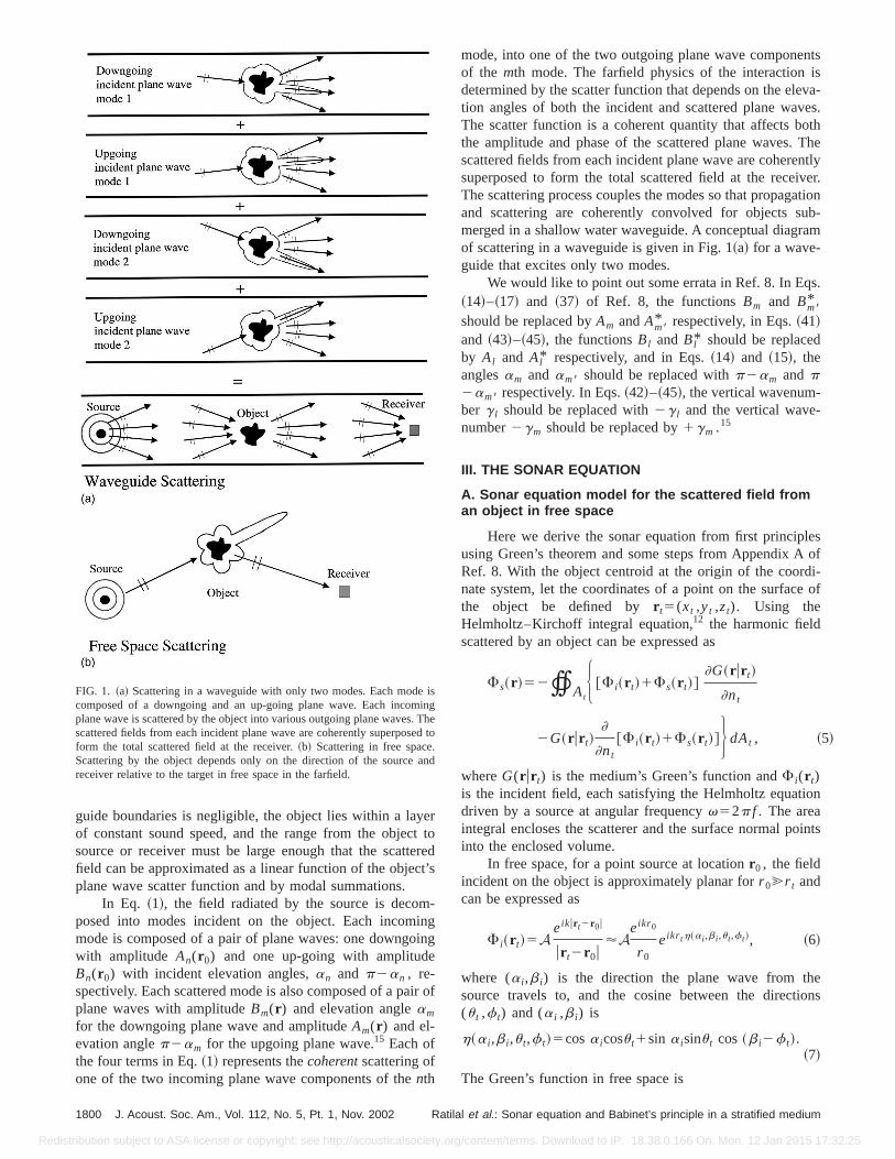
FIG. 1. ~a! Scattering in a waveguide with only two modes. Each modecomposed of a downgoing and an up-going plane wave. Each incomplane wave is scattered by the object into various outgoing plane wavesscattered fields from each incident plane wave are coherently superposform the total scattered field at the receiver.~b! Scattering in free spaceScattering by the object depends only on the direction of the sourcereceiver relative to the target in free space in the farfield.
1800 J. Acoust. Soc. Am., Vol. 112, No. 5, Pt. 1, Nov. 2002 Ratil
tribution subject to ASA license or copyright; see http://acousticalsociety.or
rtoed’s
-gg
of
mode, into one of the two outgoing plane wave componeof the mth mode. The farfield physics of the interactiondetermined by the scatter function that depends on the eltion angles of both the incident and scattered plane waThe scatter function is a coherent quantity that affects bthe amplitude and phase of the scattered plane waves.scattered fields from each incident plane wave are coheresuperposed to form the total scattered field at the receiThe scattering process couples the modes so that propagand scattering are coherently convolved for objects smerged in a shallow water waveguide. A conceptual diagrof scattering in a waveguide is given in Fig. 1~a! for a wave-guide that excites only two modes.
We would like to point out some errata in Ref. 8. In Eq~14!–~17! and ~37! of Ref. 8, the functionsBm and Bm8
*
should be replaced byAm andAm8* respectively, in Eqs.~41!
and ~43!–~45!, the functionsBl and Bl* should be replacedby Al and Al* respectively, and in Eqs.~14! and ~15!, theanglesam and am8 should be replaced withp2am and p2am8 respectively. In Eqs.~42!–~45!, the vertical wavenum-ber g l should be replaced with2g l and the vertical wave-number2gm should be replaced by1gm .15
III. THE SONAR EQUATION
A. Sonar equation model for the scattered field froman object in free space
Here we derive the sonar equation from first principusing Green’s theorem and some steps from Appendix ARef. 8. With the object centroid at the origin of the coordnate system, let the coordinates of a point on the surfacthe object be defined byr t5(xt ,yt ,zt). Using theHelmholtz–Kirchoff integral equation,12 the harmonic fieldscattered by an object can be expressed as
Fs~r !52tAtH @F i~r t!1Fs~r t!#
]G~r ur t!
]nt
2G~r ur t!]
]nt
@F i~r t!1Fs~r t!#J dAt , ~5
whereG(r ur t) is the medium’s Green’s function andF i(r t)is the incident field, each satisfying the Helmholtz equatdriven by a source at angular frequencyv52p f . The areaintegral encloses the scatterer and the surface normal pinto the enclosed volume.
In free space, for a point source at locationr0 , the fieldincident on the object is approximately planar forr 0@r t andcan be expressed as
F i~r t!5A eikur t2r0u
ur t2r0u'Aeikr 0
r 0
eikr th~a i ,b i ,u t,f t!, ~6!
where (a i ,b i) is the direction the plane wave from thsource travels to, and the cosine between the direct(u t ,f t) and (a i ,b i) is
h~a i ,b i ,u t,f t!5cosa icosu t1sin a isinu t cos~b i2f t!.~7!
The Green’s function in free space is
sgheto
nd
al et al.: Sonar equation and Babinet’s principle in a stratified medium
g/content/terms. Download to IP: 18.38.0.166 On: Mon, 12 Jan 2015 17:32:25

theeas
Redis
G~r ur t!51
4p
eikur2r tu
ur2r tu'
1
4p
eikr
re2 ikr th~a,b,u t,f t!, ~8!
eec
thfoca
es
tint t
tnere
ae
itn
J. Acoust. Soc. Am., Vol. 112, No. 5, Pt. 1, Nov. 2002 Ratilal et al.
tribution subject to ASA license or copyright; see http://acousticalsociety.or
where the last approximation is for a receiver so far fromobject thatr @r t . By application of Green’s theorem, thscattered field at this distant receiver then can be written
Fs~r !52A eikr 0
r 0
eikr
4prtAt
H S eikr th~a i ,b i ,u t,f t!1r 0
A e2 ikr 0Fs~r t!D ]
]nt
e2 ikr th~a,b,u t,f t!
2e2 ikr th~a,b,u t,f t!]
]ntS eikr th~a i ,b i ,u t,f t!1
r 0
A e2 ikr 0Fs~r t!D J dAt . ~9!
By definition of the plane wave scatter functionS(a,b,a i ,b i), however, Eq.~9! can also be written as
Fs~r !5A eikr 0
r 0
eikr
krS~a,b,a i ,b i !, ~10!
in an object-centered coordinate system, which leads to the equality
S~a,b,a i ,b i !52k
4p tAtH S eikr th~a i ,b i ,u t,f t!1
r 0
A e2 ikr 0Fs~r t!D ]
]nt
e2 ikr th~a,b,u t,f t!
2e2 ikr th~a,b,u t,f t!]
]ntS eikr th~a i ,b i ,u t,f t!1
r 0
A e2 ikr 0Fs~r t! D J dAt , ~11!
ak-
s aea-s-
eher
q.es.ni-
ofrec-
that relates Eq.~9! directly to the Green’s theorem whenr@r t .
Using the free space Green’s function, Eq.~8!, we canwrite Eq. ~10! as
Fs~r !5A~4p!2G~0ur 0!G~r u0!S~a,b,a i ,b i !
k. ~12!
From Eq. ~12!, we see that the Green’s functions that dscribe the propagation of waves from source to objG(0ur0) and from object to receiverG(r u0) are decoupledfrom the scattering functionS(a,b,a i ,b i) of the object thatgoverns the scattering process. Only the directions ofsource and the receiver relative to the object matterfarfield scattering in free space where propagation and stering effects become factorable from each other. Theproximation given in Eq.~12! is always valid in the farfield,wherer , r 0.L2/l, and may be valid at much closer rangfor certain targets, such as spheres.9 The incident wave ef-fectively arrives at the target as a plane wave propagafrom the direction of the source and the scattered wave apoint receiver behaves as a plane wave propagating fromtarget centroid. The scatter function of the target determihow a plane wave from the source is scattered in the dition of the receiver.
It is important to notice that Eq.~12! is in the frequencydomain for a time harmonic source. If the source was broband with spectrumQ( f ), the received field would be thinverse Fourier transform of the product ofQ( f ) and theright-hand side of Eq.~12!. For a broadband source signal,is impossible to separate scattering from propagation evefree space. For a narrow band source,A'Q( f )d f .
-t
er
at-p-
ghehes
c-
d-
in
Equation~10! can be recast as a sonar equation by ting 10 log of the squared magnitude of both sides,
10 logS uFs~r !u2
Pref2 D 5SL2TL~0ur0!1TS2TL~r u0!, ~13!
wherePref51 mPa,r ref51 m, and
SL520 logU APrefr ref
U dB re 1 mPa at 1 m, ~14!
TL~0ur0!520 logr 0
r ref
dB re 1 m, ~15!
TS520 logUS~a,b,a i ,b i !
kr refU dB re 1 m, ~16!
TL~0ur !520 logr
r ref
dB re 1 m. ~17!
Following the sonar equation, the radiated sound hasource level of SL, which is the sound pressure level msured at 1 m from the source. This is reduced by the tranmission loss TL(r0u0), from source to target centroid. Thlevel is augmented by the target strength TS, and furtdiminished by transmission loss TL(0ur ) from target centroidto receiver. The level of the scattered field in decibels, E~13!, is a linear combination of these incoherent quantitiThe incoherent target strength is obtained from the magtude of the free space scatter function following Eq.~16!. Itcontains only the amplitude but not the phase informationthe coherent scatter function and depends only on the di
1801: Sonar equation and Babinet’s principle in a stratified medium
g/content/terms. Download to IP: 18.38.0.166 On: Mon, 12 Jan 2015 17:32:25
on
ia
yid
tho
n
a:
a-l,in
avtharn
incsanth
al
teg
-d
be-
ren
l inpan
ticwith
inip-xi-
narn-nednar
ned
forithdel.mon-y at
gund
ich
at-tar-eennge
eraz-
Redis
tion of the source and receiver, relative to the target. A cceptual diagram of free space scattering is given in Fig. 1~b!.
B. Application of the sonar equation in a waveguide
It is common practice when using the sonar equationa waveguide to replace the transmission loss in free spwith that in the waveguide.2 This can be done analytically breplacing the free-space Green’s function with the waveguGreen’s function in Eq.~12!. Using a modal formulation, theGreen’s function in the waveguide between a point atorigin 0 and a field point atr can be expressed as a sumnormal modes,
G~r u0!5i
d~0!~8p!21/2e2 ip/4 (
m
Mmax
um~z!um~0!ei jmr
Ajmr.
~18!
Using Eqs.~2! and~4!, we can express the Green’s functioin the waveguide, Eq.~18!, as
G~r u0!5 (m
Mmax
@Am~r !2Bm~r !#. ~19!
By reciprocity,
G~0ur0!5G~r0u0!5 (n
Mmax
@An~r0!2Bn~r0!#. ~20!
Substituting the waveguide Green’s functions, Eqs.~19! and~20! into Eq. ~12!, we obtain the sonar equation approximtion for the scattered field from an object in a waveguide
Fs~r ur0!5A~4p!2S (n
Mmax
@An~r0!2Bn~r0!# D3S (
m
Mmax
@Am~r !2Bm~r !# DS~a,b,a i ,b i !
k. ~21!
The wave-theoretic model for object scattering inwaveguide, Eq.~1!, differs significantly from the sonar equation model in Eq.~21!. In the waveguide scattering modethe scattered field depends on the direction of each incomand outgoing modal plane wave. Each incoming plane wis coherentlyscattered to each outgoing plane wave byobject depending on the scatter function, which can vwith the azimuth and elevation angles of the incoming aoutgoing plane waves. In the sonar equation model, spropagation and scattering are assumed to decouple, thetered field depends only on the direction of the sourcereceiver relative to the object and not the direction ofindividual modal plane waves.
The sonar equation~21! is a special case of the genercoherent scattering formulation for a waveguide of Eq.~1!,and so is only valid under restrictive conditions. If the scatfunction remains constant over the horizontal grazing anspan of the waveguide modes6Dc for the given measurement scenario, the scatter function factors from the mosums of the waveguide scattering model, Eq.~1!, that thenreduces to the sonar equation, Eq.~21!. Propagation and
1802 J. Acoust. Soc. Am., Vol. 112, No. 5, Pt. 1, Nov. 2002 Ratil
tribution subject to ASA license or copyright; see http://acousticalsociety.or
-
nce
e
ef
-
ge
eyde
cat-d
e
rle
al
scattering are then separable, and the sonar equationcomes valid in a waveguide wherea and a i are approxi-matelyp/2 in Eq. ~21!. Target strength, along with the otheincoherent terms of the sonar equation, SL and TL, thbecome sufficient to determine the scattered field levedecibels. We approximate the horizontal grazing angle sof the waveguide modes by
6Dc56S p
22aMmaxD , ~22!
where
aMmax5tan21
jMmax
gMmax
. ~23!
Here Mmax and Dc are range-dependent, even in realisrange-independent waveguides, and tend to decreaserange due to attenuation from absorption and scatteringthe ocean, following the process known as ‘‘mode strping.’’ This is significant because the sonar equation appromation improves asDc decreases for fixedl/L.
IV. ILLUSTRATIVE EXAMPLES IN SHALLOW WATER
We now use examples to illustrate the fact that the soequation is valid when the scatter function is roughly costant over the equivalent horizontal grazing angles spanby the dominant waveguide modes. We show that the soequation is generally a good approximation~1! for all objectswhen 2Dc,l/2L, for homogeneous convex objects whe2 Dc,l/L, and ~2! for spheres and certain other roundobjects in nonforward scatter azimuths, even when~1! doesnot hold. We proceed by analyzing active sonar examplesa variety of target types and shallow water waveguides wboth the sonar equation and the waveguide scattering mo
In all the illustrative examples, a water column of 100depth is used to simulate a typical continental shelf envirment. The sound speed in the water column is isovelocit1500 m/s with a constant density of 1 g/cm3 and attenuationof 6.031025 dB/l. The seabed is either perfectly reflectinor comprised of sand or silt half-spaces. The density, sospeed, and attenuation are taken to be 1.9 g/cm3, 1700 m/s,and 0.8 dB/l for sand, 1.4 g/cm3, 1520 m/s, and 0.3 dB/l forsilt. The receiver is either colocated with the source, in whcase we calculate the backscattered field whereb i50, b5p, or in the forward azimuth of the object whereb i5b50 and we calculate the forward scattered field. The sctered fields from a disk, sphere, spheroid, and compositeget are computed as a function of increasing range betwsource–receiver and object. In all the examples, the raincreases along thex axis and depth along thez axis.
A. Effect of bottom type on the validity of the sonarequation
We use examples to illustrate how the validity of thsonar equation depends on the bottom type through the ging angle span of the waveguide modesDc. In a Pekeris
al et al.: Sonar equation and Babinet’s principle in a stratified medium
g/content/terms. Download to IP: 18.38.0.166 On: Mon, 12 Jan 2015 17:32:25
n
eld in
Redis
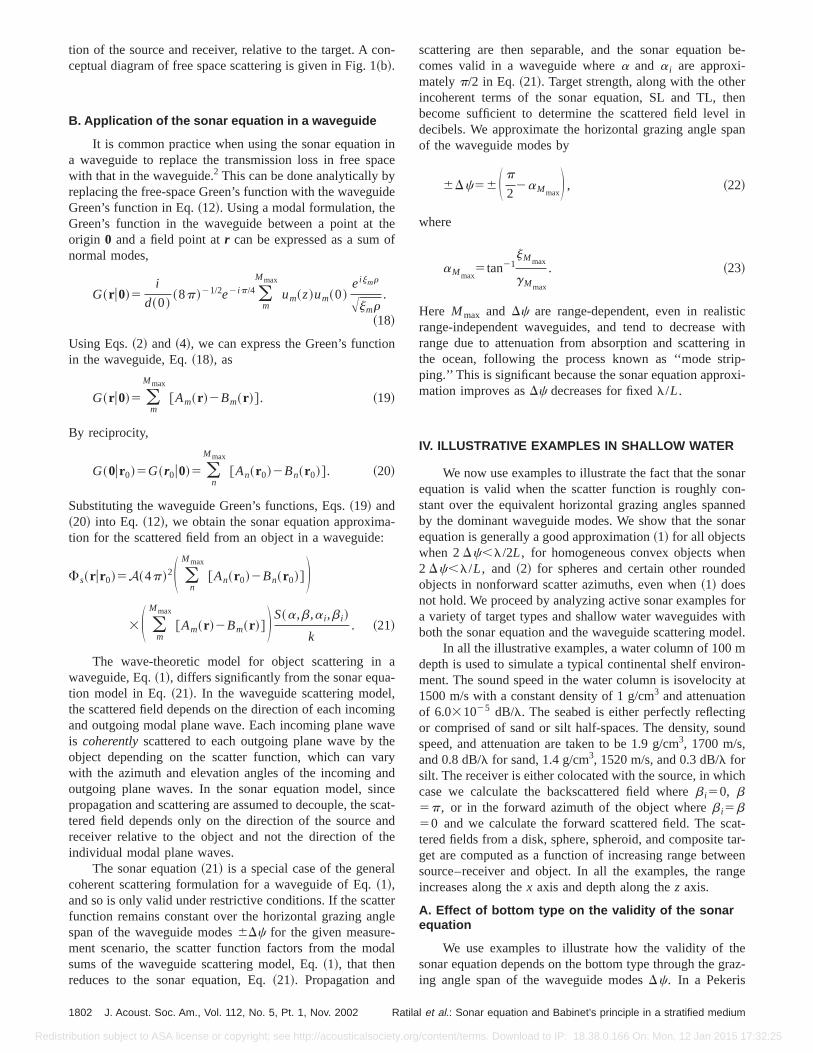
FIG. 2. The backscattered field from an upright 10 m radius rigid circular disk at 300 Hz in Pekeris waveguides with~a! silt, ~b! sand, and~c! perfectlyreflecting bottoms, respectively, calculated using the waveguide scattering model, Eq.~1!, and compared to the sonar equation, Eq.~21!. The water depth is100 m with the source–receiver and object at 50 m depth in the middle of the water column. The range increases along thex axis and depth along thez axis.The circular disk is aligned with its plane normal to thex axis. The results are plotted in decibels, i.e., 20 loguFsu, as a function of increasing range betweethe object and monostatic source–receiver. The source level is 0 dBre 1 mPa at 1 m.ka is 12.6 for this example.~d! The ratio 2Dc/(l/L) for the examplesgiven in ~a! and ~b!. For the perfectly reflecting waveguide 2Dc/(l/L) is 12.6. The sonar equation provides a good approximation to the scattered fithe waveguide when 2Dc/(l/L),1.
ofge. Aat
tieeemo
oiss
-the
is
waveguide,Dc is bounded by the critical grazing anglethe bottomcc beyond a few waveguide depths in ranwhere the leaky modes no longer contribute significantlybottom with a large sound speed contrast relative to the wcolumn has a correspondingly largecc , Mmax and Dc. Sofor fixed source frequency and object size, the sonar equaapproximation is expected to improve as this sound spcontrast decreases. We show this by examining Pekwaveguides with silt, sand, and perfectly reflecting bottothat, respectively, exhibit an increase in sound speed ctrast.
The backscattered field from a homogeneous convexject, an upright 10 m radius rigid circular disk at 300 Hz,plotted in Figs. 2~a!–~c! for the three bottom types. For thiexample, the productka5pL/l is 12.6, wherea is the ra-dius of the disk, andka is the ratio of the object circumference to the wavelength. By applying Green’s theorem,scatter function for the rigid circular disk is found to b
J. Acoust. Soc. Am., Vol. 112, No. 5, Pt. 1, Nov. 2002 Ratilal et al.
tribution subject to ASA license or copyright; see http://acousticalsociety.or
er
ond
rissn-
b-
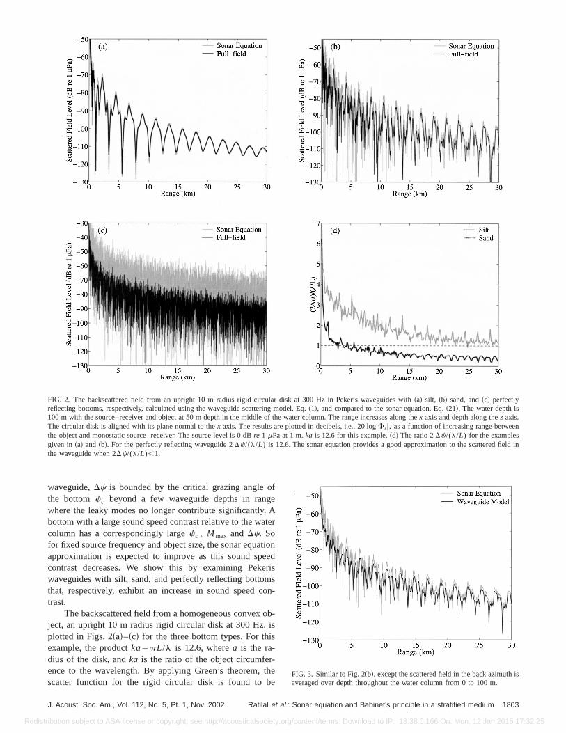
eFIG. 3. Similar to Fig. 2~b!, except the scattered field in the back azimuthaveraged over depth throughout the water column from 0 to 100 m.
1803: Sonar equation and Babinet’s principle in a stratified medium
g/content/terms. Download to IP: 18.38.0.166 On: Mon, 12 Jan 2015 17:32:25
Redis
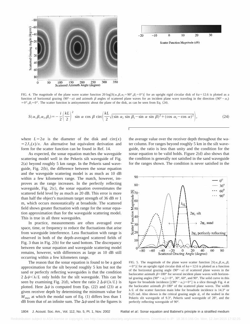
S~a,b,a i ,b i !52i
2 S kL
2 D 2
sin a cosb circS kL
2A~sin a i sin b i2sin a sin b!21~cosa i2cosa!2D , ~24!
FIG. 4. The magnitude of the plane wave scatter function 20 loguS(a,b,a i590°,b i50°)u for an upright rigid circular disk ofka512.6 is plotted as afunction of horizontal grazing~90°2a! and azimuthb angles of scattered plane waves for an incident plane wave traveling in the direction (90°2a i)50°,b i50°. The scatter function is antisymmetric about the plane of the disk, as can be seen from Eq.~24!.
d
uiigveio
dmtinheo
reue
vrii
syost
oheioe
fo
wa-e-he
idethe
en-s
thor
the
where L52a is the diameter of the disk and circ(x)52J1(x)/x. An alternative but equivalent derivation anform for the scatter function can be found in Ref. 14.
As expected, the sonar equation matches the wavegscattering model well in the Pekeris silt waveguide of F2~a! beyond roughly 5 km range. In the Pekeris sand waguide, Fig. 2~b!, the difference between the sonar equatand the waveguide scattering model is as much as 10within a few kilometers range. The match, however, iproves as the range increases. In the perfectly reflecwaveguide, Fig. 2~c!, the sonar equation overestimates tscattered field level by as much as 20 dB. This error is mthan half the object’s maximum target strength of 36 dBre 1m, which occurs monostatically at broadside. The scattefield shows greater fluctuation with range for the sonar eqtion approximation than for the waveguide scattering modThis is true in all three waveguides.
In practice, measurements are often averaged ospace, time, or frequency to reduce the fluctuations that afrom waveguide interference. Less fluctuation with rangeobserved in both of the depth-averaged scattered fieldFig. 3 than in Fig. 2~b! for the sand bottom. The discrepancbetween the sonar equation and waveguide scattering mremains, however, with differences as large as 10 dBoccurring within a few kilometers range.
The reason that the sonar equation is found to be a gapproximation for the silt beyond roughly 5 km but not tsand or perfectly reflecting waveguides is that the condit2 Dc,l/L only holds for the silt waveguide. This can bseen by examining Fig. 2~d!, where the ratio 2Dc/(l/L) isplotted. HereDc is computed from Eqs.~22! and ~23! at agiven receiver depth by determining the minimum valueMmax at which the modal sum of Eq.~1! differs less than 1dB from that of an infinite sum. TheDc used in the figures is
1804 J. Acoust. Soc. Am., Vol. 112, No. 5, Pt. 1, Nov. 2002 Ratil
tribution subject to ASA license or copyright; see http://acousticalsociety.or
de.-
nB
-g
re
da-l.
ersesof
delill
od
n
r
the average value over the receiver depth throughout theter column. For ranges beyond roughly 5 km in the silt wavguide, the ratio is less than unity and the condition for tsonar equation to be valid holds. Figure 2~d! also shows thatthe condition is generally not satisfied in the sand wavegufor the ranges shown. The condition is never satisfied in
FIG. 5. The magnitude of the plane wave scatter functionuS(a,b,a i ,b i
50°)u for an upright rigid circular disk ofka512.6 is plotted as a functionof the horizontal grazing angle~90°2a! of scattered plane waves in thbackscatter azimuthb5180° for several incident plane waves with horizotal grazing angles (90°2a i)50°, 30°, 60°, and 90°. The solid curve in thifigure for broadside incidence@(90°2a i)50°# is a slice through Fig. 4 atthe backscatter azimuthb5180° of the scattered plane waves. The widl/L of the scatter function main lobe for broadside incidence is 14.3°0.25 rad. Also shown is the critical grazing anglecc of the seabed in thePekeris slit waveguide of 9.3°, Pekeris sand waveguide of 28°, andperfectly reflecting waveguide of 90°.
al et al.: Sonar equation and Babinet’s principle in a stratified medium
g/content/terms. Download to IP: 18.38.0.166 On: Mon, 12 Jan 2015 17:32:25

ndeis
ngna-
en
mFith
esstriath
tw
there
bal, as
all
or-gid
der-ted
p-e,
Redis
perfectly reflecting waveguide because the ratio 2Dc/(l/L)is always 12.6. As expected, the performance of the soequation improves with range in realistic ocean waveguibecauseMmax andDc decrease due to modal stripping, asevident in Figs. 2~a!, ~b!, and ~d!. Note thatDc can be de-termined from Fig. 2~d! sincel/L50.25 rad or 14.3°, as cabe seen from Figs. 4 and 5. Here the scatter function matude is plotted for the upright disk, where the main lobe ha minimum width ofl/L for a plane wave incident at broadside, where (p/22a i)50.
To visualize why the sonar equation is not valid whthe condition 2Dc,(l/L) does not hold, it is instructive toplot the width of the bottom critical angle for each bottotype across the scatter function main lobe, as is done in5. When the condition does not hold, the object scattersdominant incident modes with widely varying amplitudand the scatter function cannot be approximated as a conover6Dc. In this case, both the magnitude and phase vations of the scatter function are important in describingscattering process. The sonar equationoverestimatesthelevel of the scattered field because it depends only on
J. Acoust. Soc. Am., Vol. 112, No. 5, Pt. 1, Nov. 2002 Ratilal et al.
tribution subject to ASA license or copyright; see http://acousticalsociety.or
ars
i-s
g.e
ant-
e
o
directions: those of the source and receiver relative toobject. The two relevant directions for the upright disk a(p/22a i)50 andb i50 for the incident and (p/22a)50andb5p for the scattered field. These correspond to glomaxima in both the scatter function and target strengthcan be seen in Fig. 5, which is inappropriately assigned toincoming and outgoing directions by the sonar equation.
B. Effect of object size and frequency on the validityof the sonar equation
In this section, we investigate sonar equation perfmance as a function of object size and frequency for a ricircular disk in various waveguides. At the highka of 62.8shown in Figs. 6~a!, ~c!, and~e!, the object is large compareto the wavelength and the sonar equation significantly ovestimates the scattered field level. This is to be expecfrom Fig. 6~g!, where the condition 2Dc,l/L is not satis-fied in any of the waveguides. At the lowerka of 1.3, Figs.6~b!, ~d!, and ~f!, the sonar equation provides a good aproximation in all except the perfectly reflecting waveguid
Hz
FIG. 6. Similar to Figs. 2~a!–~c!, but for an upright rigid circular disk of~a! high and~b! low ka in the Pekeris silt waveguide,~c! high and~d! low ka in thePekeris sand waveguide, and~e! high and~f! low ka in the perfectly reflecting waveguide. The highka case corresponds to a disk of 10 m radius at 1500with ka562.8 while the lowka case corresponds to a disk of 1 m radius at 300 Hz withka51.3. ~g! and~h! are similar to Fig. 2~d! but for ka of 62.8 and1.3, respectively for the cases shown in~a!–~d! in the Pekeris silt and sand waveguides. The ratio 2Dc/(l/L)562.8 for ~e! with ka of 62.8 and2 Dc/(l/L)51.3 for ~f! with ka of 1.3 in the perfectly reflecting waveguide.1805: Sonar equation and Babinet’s principle in a stratified medium
g/content/terms. Download to IP: 18.38.0.166 On: Mon, 12 Jan 2015 17:32:25

Redis
FIG. 6. ~Continued.!
any b
ns
-ly
which is consistent with the results of Fig. 6~h!, where thecondition is satisfied for the sand and silt waveguides forranges shown. This shows that the sonar equation camade valid for a given object and measurement geometr
1806 J. Acoust. Soc. Am., Vol. 112, No. 5, Pt. 1, Nov. 2002 Ratil
tribution subject to ASA license or copyright; see http://acousticalsociety.or
llbey
lowering the frequency of operation. The scatter functiofor the high and lowka cases are plotted in Figs. 7~a! and~b!, respectively. For the lowka case in the perfectly reflecting waveguide, the width of the scatter function lobe is on
e
FIG. 7. Similar to Fig. 5, but for an upright rigid circular disk of~a! ka562.8 and~b! ka51.3. The widthl/L of the scatter function main lobe for broadsidincidence@(90°2a i)50°# is 2.9° or 0.05 rad forka562.8 and 143° or 2.5 rad forka51.3.al et al.: Sonar equation and Babinet’s principle in a stratified medium
g/content/terms. Download to IP: 18.38.0.166 On: Mon, 12 Jan 2015 17:32:25
,
Redis
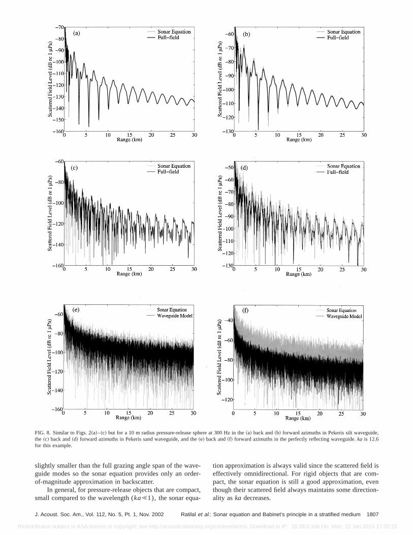
FIG. 8. Similar to Figs. 2~a!–~c! but for a 10 m radius pressure-release sphere at 300 Hz in the~a! back and~b! forward azimuths in Pekeris silt waveguidethe ~c! back and~d! forward azimuths in Pekeris sand waveguide, and the~e! back and~f! forward azimuths in the perfectly reflecting waveguide.ka is 12.6for this example.
vede
a-
is-
venion-
slightly smaller than the full grazing angle span of the waguide modes so the sonar equation provides only an orof-magnitude approximation in backscatter.
In general, for pressure-release objects that are compsmall compared to the wavelength (ka!1), the sonar equa
J. Acoust. Soc. Am., Vol. 112, No. 5, Pt. 1, Nov. 2002 Ratilal et al.
tribution subject to ASA license or copyright; see http://acousticalsociety.or
-r-
ct,
tion approximation is always valid since the scattered fieldeffectively omnidirectional. For rigid objects that are compact, the sonar equation is still a good approximation, ethough their scattered field always maintains some directality aska decreases.
1807: Sonar equation and Babinet’s principle in a stratified medium
g/content/terms. Download to IP: 18.38.0.166 On: Mon, 12 Jan 2015 17:32:25
ths,
Redis
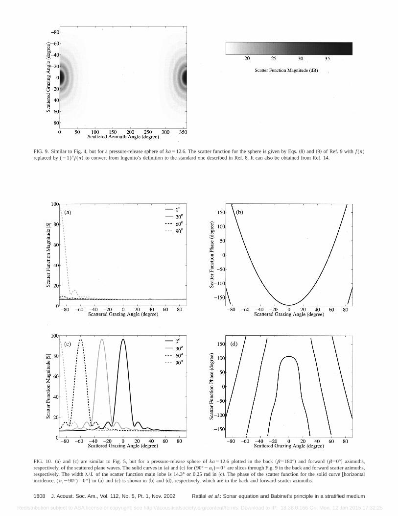
FIG. 9. Similar to Fig. 4, but for a pressure-release sphere ofka512.6. The scatter function for the sphere is given by Eqs.~8! and~9! of Ref. 9 with f (n)replaced by (21)nf (n) to convert from Ingenito’s definition to the standard one described in Ref. 8. It can also be obtained from Ref. 14.
FIG. 10. ~a! and ~c! are similar to Fig. 5, but for a pressure-release sphere ofka512.6 plotted in the back~b5180°! and forward~b50°! azimuths,respectively, of the scattered plane waves. The solid curves in~a! and~c! for (90°2a i)50° are slices through Fig. 9 in the back and forward scatter azimurespectively. The widthl/L of the scatter function main lobe is 14.3° or 0.25 rad in~c!. The phase of the scatter function for the solid curve@horizontalincidence, (a i290°)50°] in ~a! and ~c! is shown in~b! and ~d!, respectively, which are in the back and forward scatter azimuths.
1808 J. Acoust. Soc. Am., Vol. 112, No. 5, Pt. 1, Nov. 2002 Ratilal et al.: Sonar equation and Babinet’s principle in a stratified medium
tribution subject to ASA license or copyright; see http://acousticalsociety.org/content/terms. Download to IP: 18.38.0.166 On: Mon, 12 Jan 2015 17:32:25
Hz. The
Redis
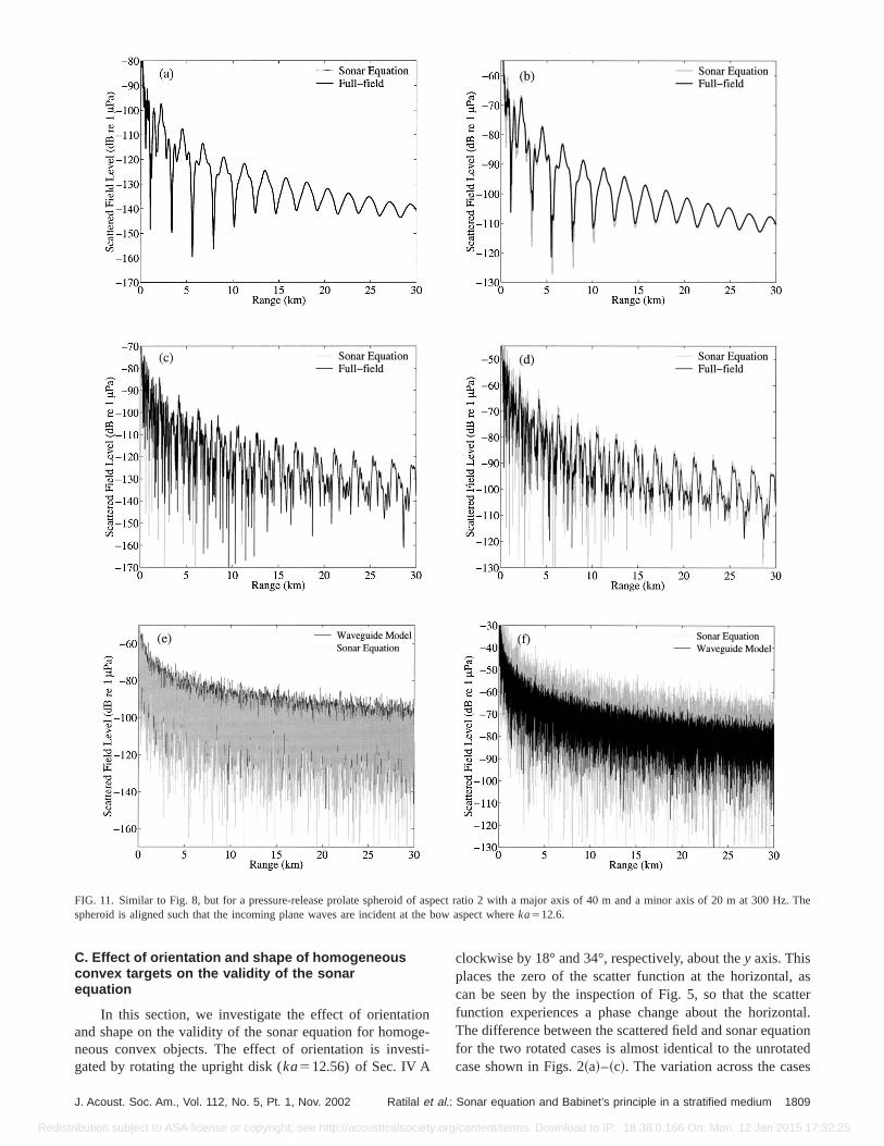
FIG. 11. Similar to Fig. 8, but for a pressure-release prolate spheroid of aspect ratio 2 with a major axis of 40 m and a minor axis of 20 m at 300spheroid is aligned such that the incoming plane waves are incident at the bow aspect whereka512.6.
ongst
, astter
ntal.tionteds
C. Effect of orientation and shape of homogeneousconvex targets on the validity of the sonarequation
In this section, we investigate the effect of orientatiand shape on the validity of the sonar equation for homoneous convex objects. The effect of orientation is invegated by rotating the upright disk (ka512.56) of Sec. IV A
J. Acoust. Soc. Am., Vol. 112, No. 5, Pt. 1, Nov. 2002 Ratilal et al.
tribution subject to ASA license or copyright; see http://acousticalsociety.or
e-i-
clockwise by 18° and 34°, respectively, about they axis. Thisplaces the zero of the scatter function at the horizontalcan be seen by the inspection of Fig. 5, so that the scafunction experiences a phase change about the horizoThe difference between the scattered field and sonar equafor the two rotated cases is almost identical to the unrotacase shown in Figs. 2~a!–~c!. The variation across the case
1809: Sonar equation and Babinet’s principle in a stratified medium
g/content/terms. Download to IP: 18.38.0.166 On: Mon, 12 Jan 2015 17:32:25
Hz. The
at 300
Redis
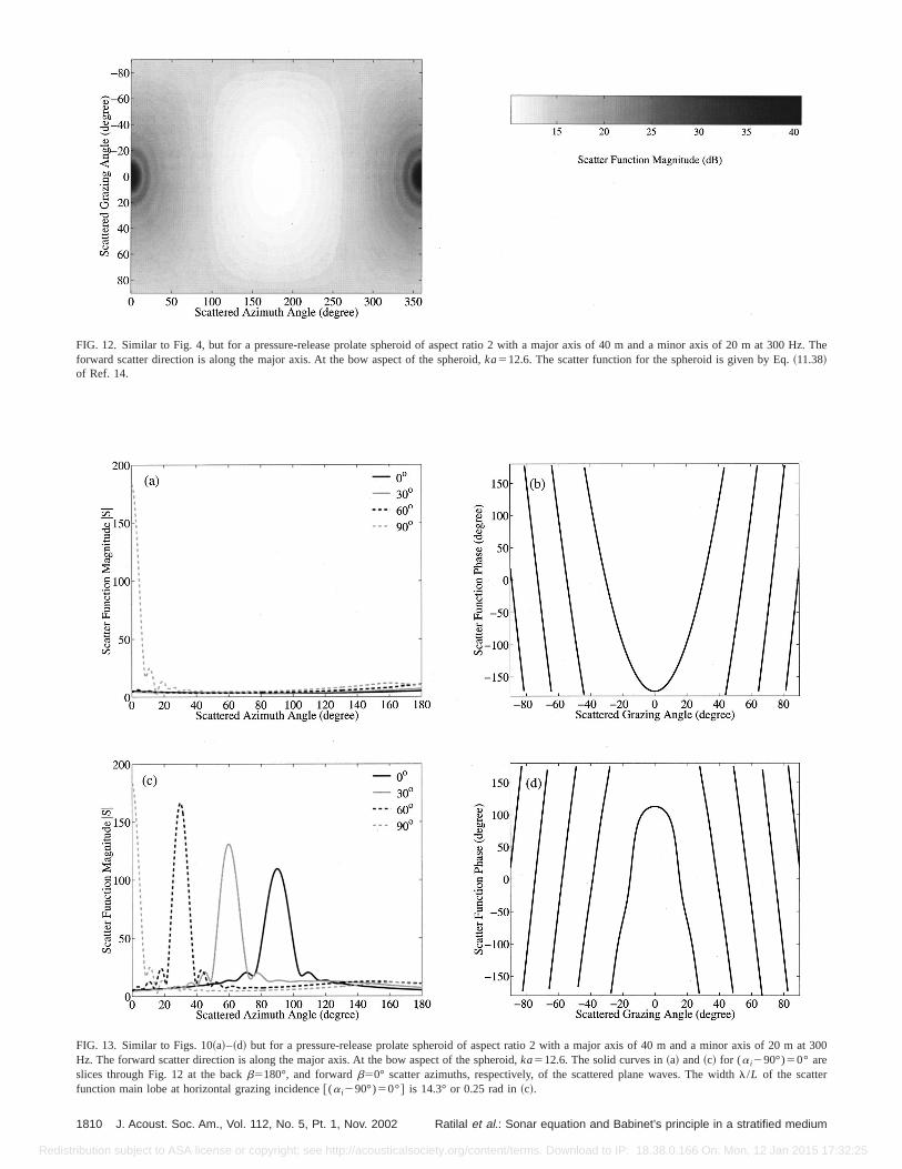
FIG. 12. Similar to Fig. 4, but for a pressure-release prolate spheroid of aspect ratio 2 with a major axis of 40 m and a minor axis of 20 m at 300forward scatter direction is along the major axis. At the bow aspect of the spheroid,ka512.6. The scatter function for the spheroid is given by Eq.~11.38!of Ref. 14.
FIG. 13. Similar to Figs. 10~a!–~d! but for a pressure-release prolate spheroid of aspect ratio 2 with a major axis of 40 m and a minor axis of 20 mHz. The forward scatter direction is along the major axis. At the bow aspect of the spheroid,ka512.6. The solid curves in~a! and~c! for (a i290°)50° areslices through Fig. 12 at the backb5180°, and forwardb50° scatter azimuths, respectively, of the scattered plane waves. The widthl/L of the scatterfunction main lobe at horizontal grazing incidence@(a i290°)50°# is 14.3° or 0.25 rad in~c!.
1810 J. Acoust. Soc. Am., Vol. 112, No. 5, Pt. 1, Nov. 2002 Ratilal et al.: Sonar equation and Babinet’s principle in a stratified medium
tribution subject to ASA license or copyright; see http://acousticalsociety.org/content/terms. Download to IP: 18.38.0.166 On: Mon, 12 Jan 2015 17:32:25
in
auooor
io
uhecerTdiecedrsknis
ctadat
rca
cac-thheonad
artethdur
cre
owefurthta
hth
mth
and
eepuchs ofig.orelypro-th,
xi-abi-larigs.
of
nt at
ofHzg
Redis
is less than roughly 1 dB for ranges beyond 1 km, showthat the condition 2Dc,l/L, as shown in Fig. 2~d!, holds,regardless of object orientation. This makes sense becthe condition states that the sonar equation will be a gapproximation if the scatter function undergoes no mthan one oscillation within6Dc. This minimizes thedestructive interference possible in multimodal propagatand scattering.
There are two limiting object shapes for homogeneoconvex objects, flat and rounded ones. Flat objects, sucthe disk examined in the previous section, are highly dirtional scatterers whenka is large. In free space, they scattthe strongest in specular and forward scatter directions.sonar equation is only valid for flat objects when the contion 2Dc,l/L holds, as demonstrated in the previous stion for an upright disk and in this section for the rotatdisk. We note that the scattered field level in the forwaazimuth is identical to that given in the back azimuth in Fig2, 3, and 6 because the scatter function for the upright disantisymmetric about the plane of the disk, as can be seeEq. ~24! and Fig. 4. The phase of the scatter functionconstant over the main lobe, as can be seen in Eq.~24!. Thisconstancy over the main lobe is characteristic of flat objewhere the narrowest lobe is always the main lobe for broside incidence. Rectangular plate examples are investigin Ref. 15.
When the condition 2Dc,l/L does not hold, the sonaequation can still be extremely accurate in nonforward ster azimuths for spheres and certain other roundedsmoothly varying convex objects. For these objects, the ster function is approximately uniform in nonforward diretions but has a main lobe in the forward direction of widl/L. This uniformity makes it possible to approximate tscatter function in nonforward azimuths as a factorable cstant over6Dc, making the sonar equation valid. The sonequation, however, will still only be valid in the forwarscatter azimuth for spheres and rounded objects when 2Dc,l/L holds because they behave like flat objects in forwscatter by Babinet’s principle. These issues will be illustrafor two smoothly varying convex objects, the sphere andprolate spheroid, in the same three waveguides examineprevious sections. Babinet’s principle will be discussed fther in Sec. V.
As expected, the sonar equation predicts the backstered field much more accurately than the forward scattefield for both the sphere and the prolate spheroid, as shin Figs. 8 and 11, respectively, for the various waveguidThis can be explained by examining the scatter function osphere, given in Ref. 14 and plotted in Figs. 9 and 10. Fig10~a! shows that the magnitude of the scatter function inbackscatter azimuth for the sphere is approximately consover6Dc in the Pekeris silt and sand waveguides, whereDccan be determined from Fig. 2~d!. Figure 10~b! shows thatthe phase of the scatter function varies by less thanp/4 over6Dc and so can be considered effectively constant. Tmeans that the scatter function can be factored frommodal sum in Eq.~1! so that propagation is decoupled froscattering. The sonar equation then becomes valid in
J. Acoust. Soc. Am., Vol. 112, No. 5, Pt. 1, Nov. 2002 Ratilal et al.
tribution subject to ASA license or copyright; see http://acousticalsociety.or
g
sede
n
sas-
he--
d.isin
s,-
ed
t-ort-
-r
ddein-
at-dn
s.aeent
ise
e
backscatter direction for the sphere in the Pekeris sandsilt waveguides.
In the perfectly reflecting waveguide,Dc is p/2 rad or90°. In this case, some higher-order modes at very stincident grazing angles near 90°, for example, scatter mstronger in the backscatter azimuth than the other modelower order that scatter more uniformly, as shown in F10~a!. The phase of the scatter function also varies by mthan 180° overDc. As a result, scattering is not completedecoupled from propagation and so the sonar equationvides only a crude approximation in the backscatter azimuas shown in Fig. 8~e!.
In the forward azimuth, the sphere scatters appromately as a flat object with the same projected area, by Bnet’s principle, and so behaves like the disk of Fig. 2. Simiconclusions can be drawn for the prolate spheroid from F
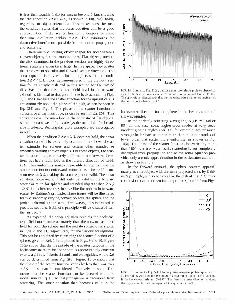
FIG. 14. Similar to Fig. 11~e!, but for a pressure-release prolate spheroidaspect ratio 5 with a major axis of 20 m and a minor axis of 4 m at 300 Hz.The spheroid is aligned such that the incoming plane waves are incidethe bow aspect whereka52.5.
FIG. 15. Similar to Fig. 5 but for a pressure-release prolate spheroidaspect ratio 5 with a major axis of 20 m and a minor axis of 4 m at 300in the backscatter azimuthb5180°. The forward scatter direction is alonthe major axis. At the bow aspect of the spheroid,ka52.5.
1811: Sonar equation and Babinet’s principle in a stratified medium
g/content/terms. Download to IP: 18.38.0.166 On: Mon, 12 Jan 2015 17:32:25
guide
Redis
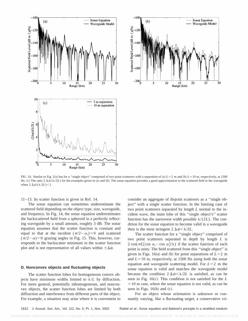
FIG. 16. Similar to Fig. 2~a! but for a ‘‘single object’’ comprised of two point scatterers with a separation of~a! L52 m and~b! L510 m, respectively, at 1500Hz. ~c! The ratio 2Dc/(l/2L) for the examples given in~a! and~b!. The sonar equation provides a good approximation to the scattered field in the wavewhen 2Dc/(l/2L),1.
tidatc
naa
r-tio
ob
ootctt
ob-f
er
ide
f
s
ar
del
n be
n-ri-
11–13. Its scatter function is given in Ref. 14.The sonar equation can sometimes underestimate
scattered field depending on the object type, size, waveguand frequency. In Fig. 14, the sonar equation underestimthe backscattered field from a spheroid in a perfectly refleing waveguide by a small amount, roughly 3 dB. The soequation assumes that the scatter function is constantequal to that at the incident (p/22a i)50 and scattered(p/22a)50 grazing angles in Fig. 15. This, however, coresponds to the backscatter minimum in the scatter funcplot and is not representative of all values within6Dc.
D. Nonconvex objects and fluctuating objects
The scatter function lobes for homogeneous convexjects have minimum widths limited tol/L by diffraction.For more general, potentially inhomogeneous, and noncvex objects, the scatter function lobes are limited by bdiffraction and interference from different parts of the objeFor example, a situation may arise where it is convenien
1812 J. Acoust. Soc. Am., Vol. 112, No. 5, Pt. 1, Nov. 2002 Ratil
tribution subject to ASA license or copyright; see http://acousticalsociety.or
hee,est-rnd
n
-
n-h.to
consider an aggregate of disjoint scatterers as a ‘‘singleject’’ with a single scatter function. In the limiting case otwo point scatterers separated by lengthL normal to the in-cident wave, the main lobe of this ‘‘single object’s’’ scattfunction has the narrowest width possiblel/(2L). The con-dition for the sonar equation to become valid in a waveguthen is the most stringent 2Dc,l/2L.
The scatter function for a ‘‘single object’’ comprised otwo point scatterers separated in depth by lengthL is2 cos(pL@cosa i2cosa#/l) if the scatter function of eachpoint is unity. The field scattered from this ‘‘single object’’ igiven in Figs. 16~a! and~b! for point separations ofL52 mandL510 m, respectively, at 1500 Hz using both the sonequation and waveguide scattering model. ForL52 m thesonar equation is valid and matches the waveguide mobecause the condition 2Dc,l/2L is satisfied, as can beseen in Fig. 16~c!. This condition is not satisfied for theL510 m case, where the sonar equation is not valid, as caseen in Figs. 16~b! and ~c!.
For an object whose orientation is unknown or costantly varying, like a fluctuating target, a conservative c
al et al.: Sonar equation and Babinet’s principle in a stratified medium
g/content/terms. Download to IP: 18.38.0.166 On: Mon, 12 Jan 2015 17:32:25
iseint
meheion0ci-
,e ofde-berea.
diuas.
Redis
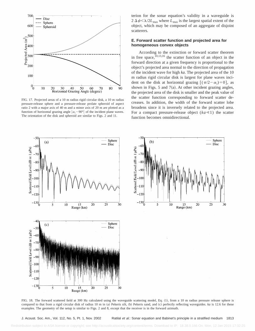
FIG. 17. Projected areas of a 10 m radius rigid circular disk, a 10 m rapressure-release sphere and a pressure-release prolate spheroid ofratio 2 with a major axis of 40 m and a minor axis of 20 m are plotted afunction of horizontal grazing angleua i290°u of the incident plane wavesThe orientation of the disk and spheroid are similar to Figs. 2 and 11.
J. Acoust. Soc. Am., Vol. 112, No. 5, Pt. 1, Nov. 2002 Ratilal et al.
tribution subject to ASA license or copyright; see http://acousticalsociety.or
terion for the sonar equation’s validity in a waveguide2 Dc,l/2Lmax whereLmax is the largest spatial extent of thobject, which may be composed of an aggregate of disjoscatterers.
E. Forward scatter function and projected area forhomogeneous convex objects
According to the extinction or forward scatter theorein free space,10,13,16 the scatter function of an object in thforward direction at a given frequency is proportional to tobject’s projected area normal to the direction of propagatof the incident wave for highka. The projected area of the 1m radius rigid circular disk is largest for plane waves indent on the disk at horizontal grazing@(p/22a i)50#, asshown in Figs. 5 and 7~a!. At other incident grazing anglesthe projected area of the disk is smaller and the peak valuthe scatter function corresponding to forward scattercreases. In addition, the width of the forward scatter lobroadens since it is inversely related to the projected aFor a compact pressure-release object (ka!1) the scatterfunction becomes omnidirectional.
sspecta
is
FIG. 18. The forward scattered field at 300 Hz calculated using the waveguide scattering model, Eq.~1!, from a 10 m radius pressure release spherecompared to that from a rigid circular disk of radius 10 m in~a! Pekeris silt,~b! Pekeris sand, and~c! perfectly reflecting waveguides.ka is 12.6 for theseexamples. The geometry of the setup is similar to Figs. 2 and 8, except that the receiver is in the forward azimuth.1813: Sonar equation and Babinet’s principle in a stratified medium
g/content/terms. Download to IP: 18.38.0.166 On: Mon, 12 Jan 2015 17:32:25
d a rigidto Figs.
Redis
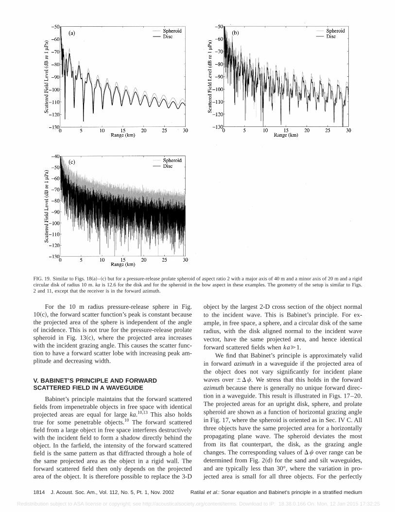
FIG. 19. Similar to Figs. 18~a!–~c! but for a pressure-release prolate spheroid of aspect ratio 2 with a major axis of 40 m and a minor axis of 20 m ancircular disk of radius 10 m.ka is 12.6 for the disk and for the spheroid in the bow aspect in these examples. The geometry of the setup is similar2 and 11, except that the receiver is in the forward azimuth.
Fiusnlaenm
eca
eheed
hte
3-
alx-amevetical
idf
nedec-0.lategleAlltallyost
gle
,ro-tly
For the 10 m radius pressure-release sphere in10~c!, the forward scatter function’s peak is constant becathe projected area of the sphere is independent of the aof incidence. This is not true for the pressure-release prospheroid in Fig. 13~c!, where the projected area increaswith the incident grazing angle. This causes the scatter fution to have a forward scatter lobe with increasing peak aplitude and decreasing width.
V. BABINET’S PRINCIPLE AND FORWARDSCATTERED FIELD IN A WAVEGUIDE
Babinet’s principle maintains that the forward scatterfields from impenetrable objects in free space with identiprojected areas are equal for largeka.10,13 This also holdstrue for some penetrable objects.10 The forward scatteredfield from a large object in free space interferes destructivwith the incident field to form a shadow directly behind tobject. In the farfield, the intensity of the forward scatterfield is the same pattern as that diffracted through a holethe same projected area as the object in a rigid wall. Tforward scattered field then only depends on the projecarea of the object. It is therefore possible to replace the
1814 J. Acoust. Soc. Am., Vol. 112, No. 5, Pt. 1, Nov. 2002 Ratil
tribution subject to ASA license or copyright; see http://acousticalsociety.or
g.e
gletesc--
dl
ly
ofedD
object by the largest 2-D cross section of the object normto the incident wave. This is Babinet’s principle. For eample, in free space, a sphere, and a circular disk of the sradius, with the disk aligned normal to the incident wavector, have the same projected area, and hence idenforward scattered fields whenka@1.
We find that Babinet’s principle is approximately valin forward azimuthin a waveguide if the projected area othe object does not vary significantly for incident plawaves over6Dc. We stress that this holds in the forwarazimuthbecause there is generally no unique forward dirtion in a waveguide. This result is illustrated in Figs. 17–2The projected areas for an upright disk, sphere, and prospheroid are shown as a function of horizontal grazing anin Fig. 17, where the spheroid is oriented as in Sec. IV C.three objects have the same projected area for a horizonpropagating plane wave. The spheroid deviates the mfrom its flat counterpart, the disk, as the grazing anchanges. The corresponding values ofDc over range can bedetermined from Fig. 2~d! for the sand and silt waveguidesand are typically less than 30°, where the variation in pjected area is small for all three objects. For the perfec
al et al.: Sonar equation and Babinet’s principle in a stratified medium
g/content/terms. Download to IP: 18.38.0.166 On: Mon, 12 Jan 2015 17:32:25
Redis
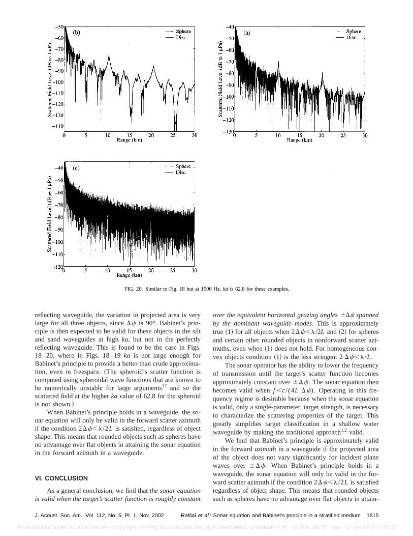
FIG. 20. Similar to Fig. 18 but at 1500 Hz.ka is 62.8 for these examples.
er
s
igs
asn
oth
cthti
n
azi-n-
cyes
n
ationsaryhis
ter
idane
r-
jectsttain-
reflecting waveguide, the variation in projected area is vlarge for all three objects, sinceDc is 90°. Babinet’s prin-ciple is then expected to be valid for these objects in theand sand waveguides at highka, but not in the perfectlyreflecting waveguide. This is found to be the case in F18–20, where in Figs. 18–19ka is not large enough forBabinet’s principle to provide a better than crude approximtion, even in freespace.~The spheroid’s scatter function icomputed using spheroidal wave functions that are knowbe numerically unstable for large arguments17 and so thescattered field at the higherka value of 62.8 for the spheroidis not shown.!
When Babinet’s principle holds in a waveguide, the snar equation will only be valid in the forward scatter azimuif the condition 2Dc,l/2L is satisfied, regardless of objeshape. This means that rounded objects such as spheresno advantage over flat objects in attaining the sonar equain the forward azimuth in a waveguide.
VI. CONCLUSION
As a general conclusion, we find thatthe sonar equationis valid when the target’s scatter function is roughly consta
J. Acoust. Soc. Am., Vol. 112, No. 5, Pt. 1, Nov. 2002 Ratilal et al.
tribution subject to ASA license or copyright; see http://acousticalsociety.or
y
ilt
.
-
to
-
aveon
t
over the equivalent horizontal grazing angles6Dc spannedby the dominant waveguide modes. This is approximatelytrue ~1! for all objects when 2Dc,l/2L and~2! for spheresand certain other rounded objects in nonforward scattermuths, even when~1! does not hold. For homogeneous covex objects condition~1! is the less stringent 2Dc,l/L.
The sonar operator has the ability to lower the frequenof transmission until the target’s scatter function becomapproximately constant over6Dc. The sonar equation thebecomes valid whenf ,c/(4L Dc). Operating in this fre-quency regime is desirable because when the sonar equis valid, only a single-parameter, target strength, is necesto characterize the scattering properties of the target. Tgreatly simplifies target classification in a shallow wawaveguide by making the traditional approach1,2 valid.
We find that Babinet’s principle is approximately valin the forwardazimuthin a waveguide if the projected areof the object does not vary significantly for incident plawaves over6Dc. When Babinet’s principle holds in awaveguide, the sonar equation will only be valid in the foward scatter azimuth if the condition 2Dc,l/2L is satisfiedregardless of object shape. This means that rounded obsuch as spheres have no advantage over flat objects in a
1815: Sonar equation and Babinet’s principle in a stratified medium
g/content/terms. Download to IP: 18.38.0.166 On: Mon, 12 Jan 2015 17:32:25
ve
,
t’sst
st.
b-So
ed
Am.
b-,’’ J.
f
y insis,
a
pt.
Redis
ing the sonar equation in the forward azimuth in a waguide.
1R. J. Urick, Principles of Underwater Sound~McGraw-Hill, New York,1983!.
2National Defence Research Committee,Physics of Sound in the Sea~Pen-insula, Los Altos, 1989!.
3F. B. Jensen, W. A. Kuperman, M. B. Porter, and H. Schmidt,Computa-tional Ocean Acoustics~American Institute of Physics, Woodbury, NY1994!.
4W. S. Burdic, Underwater Acoustic System Analysis~Prentice–Hall,Englewood Cliffs, NJ, 1991!.
5L. E. Kinsler, A. R. Frey, A. B. Coppens, and J. V. Sanders,Fundamentalsof Acoustics~Wiley, New York, 1982!.
6N. C. Makris and P. Ratilal, ‘‘Validity of the sonar equation and Babineprinciple for object scattering in a shallow water waveguide,’’ J. AcouSoc. Am.106, 2158~1999!.
7F. Ingenito, ‘‘Scattering from an object in a stratified medium,’’ J. AcouSoc. Am.82, 2051–2059~1987!.
8N. C. Makris and P. Ratilal, ‘‘A unified model for reverberation and sumerged object scattering in a stratified ocean waveguide,’’ J. Acoust.Am. 109, 909–941~2001!.
9N. C. Makris, ‘‘A spectral approach to 3-D object scattering in layer
1816 J. Acoust. Soc. Am., Vol. 112, No. 5, Pt. 1, Nov. 2002 Ratil
tribution subject to ASA license or copyright; see http://acousticalsociety.or
-
.
c.
media applied to scattering from submerged spheres,’’ J. Acoust. Soc.104, 2105–2113~1998!; 106, 518 ~1999! ~Erratum!.
10H. C. van de Hulst,Light Scattering by Small Particles~Dover, New York,1981!.
11N. C. Makris, F. Ingenito, and W. A. Kuperman, ‘‘Detection of a sumerged object insonified by surface noise in an ocean waveguideAcoust. Soc. Am.96, 1703–1724~1994!.
12P. M. Morse and K. U. Ingard,Theoretical Acoustics~Princeton UniversityPress, Princeton, NJ, 1986!, pp. 418–436.
13M. Born and E. Wolf,Principles of Optics, Electromagnetic Theory oPropagation Interference and Diffraction of Light, 6th ed. ~CambridgeUniversity Press, Cambridge, 1980!.
14J. J. Bowman, T. B. A. Senior, and P. L. E. Uslenghi, inElectromagneticand Acoustic Scattering by Simple Shapes~North-Holland, Amsterdam,1969!.
15P. Ratilal, ‘‘Remote sensing of submerged objects and geomorphologcontinental shelf waters with acoustic waveguide scattering,’’ Ph.D. theMIT, Cambridge, MA, 2002.
16P. Ratilal and N. C. Makris, ‘‘Extinction theorem for object scattering instratified medium,’’ J. Acoust. Soc. Am.110, 2924~2001!.
17S. Asano, ‘‘Light scattering properties of spheroidal particles,’’ Appl. O18, 712–723~1979!.
al et al.: Sonar equation and Babinet’s principle in a stratified medium
g/content/terms. Download to IP: 18.38.0.166 On: Mon, 12 Jan 2015 17:32:25